EP2596749B1 - Verfahren und System zur Verarbeitung von medizinischen Bilderdatensätzen - Google Patents
Verfahren und System zur Verarbeitung von medizinischen Bilderdatensätzen Download PDFInfo
- Publication number
- EP2596749B1 EP2596749B1 EP12194063.9A EP12194063A EP2596749B1 EP 2596749 B1 EP2596749 B1 EP 2596749B1 EP 12194063 A EP12194063 A EP 12194063A EP 2596749 B1 EP2596749 B1 EP 2596749B1
- Authority
- EP
- European Patent Office
- Prior art keywords
- image
- dataset
- volume
- medical scan
- plane
- Prior art date
- Legal status (The legal status is an assumption and is not a legal conclusion. Google has not performed a legal analysis and makes no representation as to the accuracy of the status listed.)
- Active
Links
Images





Classifications
-
- A—HUMAN NECESSITIES
- A61—MEDICAL OR VETERINARY SCIENCE; HYGIENE
- A61B—DIAGNOSIS; SURGERY; IDENTIFICATION
- A61B6/00—Apparatus or devices for radiation diagnosis; Apparatus or devices for radiation diagnosis combined with radiation therapy equipment
- A61B6/46—Arrangements for interfacing with the operator or the patient
- A61B6/461—Displaying means of special interest
- A61B6/463—Displaying means of special interest characterised by displaying multiple images or images and diagnostic data on one display
-
- A—HUMAN NECESSITIES
- A61—MEDICAL OR VETERINARY SCIENCE; HYGIENE
- A61B—DIAGNOSIS; SURGERY; IDENTIFICATION
- A61B6/00—Apparatus or devices for radiation diagnosis; Apparatus or devices for radiation diagnosis combined with radiation therapy equipment
- A61B6/46—Arrangements for interfacing with the operator or the patient
- A61B6/461—Displaying means of special interest
- A61B6/466—Displaying means of special interest adapted to display 3D data
-
- A—HUMAN NECESSITIES
- A61—MEDICAL OR VETERINARY SCIENCE; HYGIENE
- A61B—DIAGNOSIS; SURGERY; IDENTIFICATION
- A61B6/00—Apparatus or devices for radiation diagnosis; Apparatus or devices for radiation diagnosis combined with radiation therapy equipment
- A61B6/52—Devices using data or image processing specially adapted for radiation diagnosis
- A61B6/5211—Devices using data or image processing specially adapted for radiation diagnosis involving processing of medical diagnostic data
- A61B6/5223—Devices using data or image processing specially adapted for radiation diagnosis involving processing of medical diagnostic data generating planar views from image data, e.g. extracting a coronal view from a 3D image
-
- A—HUMAN NECESSITIES
- A61—MEDICAL OR VETERINARY SCIENCE; HYGIENE
- A61B—DIAGNOSIS; SURGERY; IDENTIFICATION
- A61B6/00—Apparatus or devices for radiation diagnosis; Apparatus or devices for radiation diagnosis combined with radiation therapy equipment
- A61B6/52—Devices using data or image processing specially adapted for radiation diagnosis
- A61B6/5211—Devices using data or image processing specially adapted for radiation diagnosis involving processing of medical diagnostic data
- A61B6/5229—Devices using data or image processing specially adapted for radiation diagnosis involving processing of medical diagnostic data combining image data of a patient, e.g. combining a functional image with an anatomical image
- A61B6/5235—Devices using data or image processing specially adapted for radiation diagnosis involving processing of medical diagnostic data combining image data of a patient, e.g. combining a functional image with an anatomical image combining images from the same or different ionising radiation imaging techniques, e.g. PET and CT
-
- A—HUMAN NECESSITIES
- A61—MEDICAL OR VETERINARY SCIENCE; HYGIENE
- A61B—DIAGNOSIS; SURGERY; IDENTIFICATION
- A61B6/00—Apparatus or devices for radiation diagnosis; Apparatus or devices for radiation diagnosis combined with radiation therapy equipment
- A61B6/52—Devices using data or image processing specially adapted for radiation diagnosis
- A61B6/5211—Devices using data or image processing specially adapted for radiation diagnosis involving processing of medical diagnostic data
- A61B6/5229—Devices using data or image processing specially adapted for radiation diagnosis involving processing of medical diagnostic data combining image data of a patient, e.g. combining a functional image with an anatomical image
- A61B6/5247—Devices using data or image processing specially adapted for radiation diagnosis involving processing of medical diagnostic data combining image data of a patient, e.g. combining a functional image with an anatomical image combining images from an ionising-radiation diagnostic technique and a non-ionising radiation diagnostic technique, e.g. X-ray and ultrasound
-
- A—HUMAN NECESSITIES
- A61—MEDICAL OR VETERINARY SCIENCE; HYGIENE
- A61B—DIAGNOSIS; SURGERY; IDENTIFICATION
- A61B6/00—Apparatus or devices for radiation diagnosis; Apparatus or devices for radiation diagnosis combined with radiation therapy equipment
- A61B6/02—Arrangements for diagnosis sequentially in different planes; Stereoscopic radiation diagnosis
- A61B6/03—Computed tomography [CT]
- A61B6/032—Transmission computed tomography [CT]
-
- A—HUMAN NECESSITIES
- A61—MEDICAL OR VETERINARY SCIENCE; HYGIENE
- A61B—DIAGNOSIS; SURGERY; IDENTIFICATION
- A61B6/00—Apparatus or devices for radiation diagnosis; Apparatus or devices for radiation diagnosis combined with radiation therapy equipment
- A61B6/02—Arrangements for diagnosis sequentially in different planes; Stereoscopic radiation diagnosis
- A61B6/03—Computed tomography [CT]
- A61B6/037—Emission tomography
Definitions
- the present invention concerns the processing of datasets obtained during medical scans.
- CT Computed Tomography
- US Ultrasound
- MRI Magnetic Resonance Imaging
- SPECT Single Photon Emission Tomography
- PET Positron Emission Tomography
- a medical scan provides a 'dataset'.
- the dataset comprises digital information about the value of a variable at each of many points.
- the points are different spatial locations that are spread throughout 3 physical dimensions, i.e. each point is at a particular location on a three dimensional grid.
- the variable may typically be an intensity measurement.
- the intensity may be, for example, an indication of the X-Ray attenuation of the tissue at each particular point.
- the element of the scan image located at a particular spatial location may be referred to as a 'voxel'.
- a voxel is therefore analogous to a 'pixel' of a conventional 2-Dimensional image.
- the dataset of the medical scan is 3-Dimensional, it is typically displayed to a user as a two dimensional image on a medical imaging workstation.
- An image slice from a 3-d dataset is simply a 2-d representation, consisting of those data points that lie on a particular 2-d plane through the 3-d image.
- a typical 3-d dataset such as one from an MRI scan, will have a matrix of regularly spaced data points.
- the MRI-scan may have data points whose centres are spaced by 1 millimetre in the x- and y- directions across any plane of the scan. Consecutive planes may, for example, be parallel and separated by 7 millimetres.
- the 3-D scan may therefore be divided up into tens or hundreds of parallel 2-D images, for display purposes.
- the user of a workstation can then flick through the images in sequence, for example, thereby allowing a view of successive cross sections of the tissue that was scanned.
- Typical workstations allow the 2-D slices to be viewed individually, or sequentially in successive steps.
- the view may typically be along a selected one of three perpendicular directions.
- the axes of the three perpendicular directions may, for example, be along the 'long axis' of the body, 'across' the body from one side to the other, and through the body from top to bottom. These axes are conventionally referred to as:
- the term 'dataset' should be construed as meaning a three dimensional dataset that results from performing a medical scan. However, when the scan image is displayed, only a two dimensional slice of the dataset may be on view at any one time as an image.
- Medical scan images may include information about a wide variety of anatomical features and structures.
- a scan image may show various types of healthy tissue, such as bone and organs within the body.
- a scan image may also show abnormal tissues.
- the purpose of obtaining a medical scan image is often to detect abnormal tissue. So, a typical example of an application of medical imaging is in the identification and 'staging' of cancerous tumours.
- Multiple modalities may be used to provide medical scan images. This approach involves obtaining scan images of the same region of tissue by more than one modality. For example, the same region of tissue may be imaged using both a PET scan and a CT scan. Scanners that can carry out multiple mode scans are referred to as “hybrid scanners”. Typically, a hybrid scanner allows the subject to be scanned by both modalities in the same sitting.
- Figures 1-3 are shown on a single page, in order to facilitate comparison between the three approaches.
- One approach presents a first image as a base layer, over which one or more semi-transparent overlays are displayed. This approach is known as a 'fused view' in medical imaging. This approach enables the user to view one image, whilst being able to view and use information from overlying images that are derived from another dataset.
- MR images are typically highly anisotropic, which means that the voxels may not be cuboid.
- the voxels may typically be 3mm x 0.3mm x 8mm.
- Such images are best viewed in their original orientation, and do not produce clear images if rotated or warped. This is a major constraint on known imaging systems.
- the present invention therefore relates to display logic and/or image processing steps required to produce convenient displays of multiple images which have been acquired in a set.
- Medical image display software typically renders 3D scans as 2D cuts through the 3D volume.
- a processing step known as “volume reconstruction” is used to create a 3D volume from the stack of 2D images produced by the scanner.
- the resulting displays are called “Multi-Planar Reconstructions" or MPRs for short.
- MPRs Multi-Planar Reconstructions
- Some software provides the user the ability to adjust the orientation of the view. Each view has an orientation, position and extent which determines exactly which part of the 3D image is shown. In some advanced visualisation software it is possible to define views where the orientation is not a plane, but is a curved cut of the 3D volume.
- MR images are very typically acquired using:
- CT and PET images may be gated against some physiological process such as breathing, or acquired dynamically to capture a biological process of the subject as a function of time. In other situations, multiple acquisitions may be made in the same sitting of different parts of the body.
- each such group of images is forming a single group or set, for storage, transmission, display and manipulation purposes.
- the groups may be given different names, according to the context and type of acquisition. For example:
- 3D volumes Many known medical image workstations provide good tools to display and manipulate single 3D volumes. More challenging is the problem of display and manipulation of multiple 3D volumes.
- the user may wish to load and visualise 3D scans acquired from different scanners, e.g. a CT and MRI scan of the same patient.
- the user may wish to compare the same type of scan taken at different points in time, for example to assess the change in disease over time, or to measure response to therapy.
- One or both scans may comprise multi-volume datasets.
- first datasets that are not multi-volume on requirement is to align the images. These are pairs of images taken from two different datasets, for example an MRI scan and a CT scan of the same patient.
- the process of aligning images is known as ' image registration '.
- Rigid, affine and deformable image registration methods shown in figure 1 can be used to correct for differences, to various extents. Use of these image registration techniques therefore makes the assessment of aligned images an easier process.
- Another attribute of such software packages is the ability to create both 'fused' and 'side-by-side' displays of the aligned images.
- the fused display one image is shown in a view and another image shown as a semi-transparent overlay on the same view.
- the overlay image is typically transformed and resampled according to the alignment calculated by the registration method.
- Side-by-side displays show the aligned datasets in non-fused views. However, they "bind" the scroll and zoom controls of the displays, such that they are always displayed in alignment.
- Some software tools also place a cursor or cross-hair on each display, and keep these in alignment as the user adjusts them.
- MPR views may also be referred to as "hanging protocols" in the field of medical imaging.
- the display parameters such that they are correlated or synchronised.
- the two or more datasets each comprise a set of CT images taken at one sitting. It is useful to bind the zoom and pan settings of the views, such that the corresponding anatomical locations in the CTs can be visualised simultaneously.
- Display controls such as Window and Level, analogous to brightness and contrast controls, are also useful to bind under certain situations.
- a typical example might be where one dataset is a multisequence MRI scan, consisting of images acquired in at least two different orientations.
- a second dataset to be displayed at the same time as the first might be a CT scan taken of the same subject.
- Such a multi-sequence MRI dataset may use different imaging parameters for the different sequences, or different MRI sequences within the dataset may typically relate to different parts of the body.
- Conventional approaches to display and manipulation of one view from the MRI scan and one form the CT scan will not work well.
- MRI protocols used in diagnostic practice typically acquire a set of thickly sliced images. These images have a much greater spacing between images than the voxel size within each image slice. Such images would be best viewed in their original orientation. However, since each image may have a different orientation, the view on known displays cannot be configured to produce good quality displays.
- a method having the steps of appended claim 1 is provided.
- a hybrid medical imaging scanner having the features of appended claim 12 is provided. Steps and features of detailed embodiments are provided in the dependent claims.
- the present invention provides control logic and a display that can dynamically adjust the viewing properties of displays of images derived from medical scan datasets. This may be achieved in a consistent manner.
- the invention may provide more detailed views than prior art systems, when starting with the same medical scan datasets.
- the invention may automate some tasks, thereby speeding up the process of displaying high quality images of multiple datasets.
- One or both datasets may be subjected to a full volume reconstruction.
- one image derived from the multi-sequence MR dataset will be displayed simultaneously with one image derived from the CT scan dataset.
- a transformation is used to map locations in each MR image with locations in the CT image that is displayed together with that MR image.
- Such a transformation may be determined through the use of a registration algorithm.
- the transformation may be of the rigid, affine or deformable type, as shown in figures 1-3 .
- all of the MRI slices in the dataset are acquired in the same sitting, and therefore the mutual relationship between each of these is known.
- the user is presented with pairs of views in sequence.
- Each pair comprises an image from the MRI dataset, and an image from the CT dataset.
- the MRI dataset is a multi-sequence dataset, i.e. an example of a multi-volume dataset. So the MRI dataset itself includes:
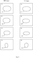
- Figure 4 shows examples of the pairs of images that are provided in this example.
- Figure 4 shows a 'side-by-side' display, rather than a fused view with one image overlayed on the other.
- images 410, 430, 450 and 470 show consecutive images derived from the MRI dataset. Each image is one slice from the multi-sequence set.
- Images 420, 440, 460 and 480 each show an image of a slice of the CT dataset.
- images 410 and 420 are displayed together, simultaneously. After images 410 and 420 have been displayed, images 430 and 440 may be displayed together. Then images 450 and 460 may be displayed together. Finally, images 470 and 480 may be displayed together.
- Image 410 from the MRI set is displayed simultaneously with image 420 from the CT dataset.
- Object 415 in image 410 is a representation of a cross-section through a 3-D object, such as an organ in a patient.
- Object 425 in image 420 corresponds to object 415.
- the term 'object' should be construed widely, and may typically mean a larger volume of tissue than just an organ, for example, the object may be a whole human subject.
- Image 410 corresponds to one acquisition plane of a first volume of the MRI dataset. Given that there may be a significant separation between the slices that make up the MRI dataset, this is important. It means that object 415 will be shown with the highest resolution possible from the voxels of the original dataset that was acquired. Image 410 results from performing a full volume reconstruction for either the entire MRI dataset, or the first volume of the MRI dataset.
- Image 420 derived from the CT dataset results from determining a surface through the CT volume that corresponds in some way to that of image 410 i.e. the acquisition orientation of the first MRI dataset. This may be achieved through the use of a transformation that maps datapoints in MRI volume to datapoints in the CT dataset. Such a transformation may be obtained through the use of a registration algorithm. Images 410 and 420 both lie in the same plane, which is the plane of acquisition of image 410. Clearly, if a deformable registration exists between the MRI and CT volumes, then the plane in the MRI would be planar, whereas it might map onto a curved surface in the CT. An alternative is to select the plane in the CT that corresponds to the plane with the same orientation as image 410, pivoted at a location found through the use of a deformable registration.
- Images 410 and 420, and hence object representations 415 and 425, can then be displayed simultaneously.
- image 430 from the MRI dataset and image 440 from the CT dataset may be derived, and displayed simultaneously.
- the object shown as 415 in image 410 is also visible on view 430, as object 435.
- the plane of view of image 430 is different from that of image 410. So the object 435 may, for example, be slightly smaller than object 415. This might occur if image 430 were in a plane parallel to the plane of image 410, but at a location further along the organ than the location in which images 410 and 420 were taken. If the organ were tapering, i.e. had a smaller cross-sectional area in the plane of the image 430, then it would appear smaller as object 435 in image 430.
- images 410 and 430 are successive, parallel images from the first volume of the multi-sequence MRI dataset.
- Image 440 is derived from the CT dataset, and lies in the same plane as image 430. Object 445 would therefore also be slightly smaller than object 425, as shown.
- images 420 and 440 may need simply to be selected from the CT dataset. However, in general terms, images 420 and 440 will result from a re-slicing of the CT dataset, which can only be done once the acquisition planes of images 410 and 430 are known. If images 410 and 430 are from an MRI scan, and were acquired in planes specified by a user that did not correspond to axial, coronal or saggital, then the CT dataset will need to be re-sliced. After this re-slicing, images 420 and 440 will be in planes that correspond to the acquisition planes of images 410 and 430.
- Image 450 from the MRI dataset shows object 455, which is slightly smaller than object 435.
- Image 450 may be in an acquisition plane parallel to images 410 and 430, and be further along a first volume of images than image 430.
- Image 460 is from the CT dataset, and is in a plane corresponding to the acquisition plane of image 450.
- Image 470 is from a second image series of the MRI dataset. It may show a completely different object 475 than objects 415, 435 and 455.
- Object 475 may be either:
- Image 470 may be selected by a user, who has seen enough of the first series of images once images 410, 430 and 450 have been displayed. However, image 470 may be displayed automatically, once the last of the images in the first series f the MR scan has been displayed.
- objects 415, 435 and 455 may be three views of the liver of a patient. These may, for example, show tumours.
- Image 470 may be from a second series of the MRI scan, showing the head of the patient. The user may select image 470, in order to be able to check the head for 'secondary' tumours.
- the simultaneous display of images 420, 440, 460 and 480 will enable the user to see the information derivable from the CT scan of the whole patient, in the same plane.
- the invention introduces a new type of view, which is termed the 'Acquisition view'.
- the Acquisition view synchronises the orientation of the view on the display to that of the orientation of the dataset being viewed.
- the orientation may simply correspond to one of the standard orientations 'axial', 'coronal' or 'saggital', or may be some other angle, a so-called 'off-axis' views.
- the Acquisition view adjusts the view orientation to match the orientation of the dataset, such that the user is always viewing data in its acquired orientation.
- the benefits for users may be greatest when switching to display of the next volume of the multi-volume dataset.
- This next volume may be the next series of a multi-series MRI dataset, or may be the next phase of a multi-phase CT scan dataset.
- hybrid scanners can now provide a combined MRI and CT scan of a patient, at one sitting. Alternatively, they may provide a combined MRI scan and a PET scan. Some scanners may provide each of an MRI, CT and PET scan dataset, and one or more of these may be a multi-volume dataset. The present invention may help with the manipulation and detail of view available from these datasets.
- the invention may provide advantages for MRI where the in-plane resolution, that is the resolution within each acquired slice, is typically much higher than between slices.
- each voxel of an MRI slice may be 0.5mm or less within the slice. However, it may be 5mm or 8mm between slices. Therefore, for optimal display MRI datasets are best viewed in their acquisition orientation.
- Such coarse 2D slices may be treated in conventional scanners and medical imaging workstations in the same way as other scans, such as CT, which have fine resolution both in the plane of acquisition and with finely spaced planes of acquisition.
- the invention may provide the Acquisition as a new type of view, available for user selection.
- the Acquisition view may be one of a set of views offered to a user, for selection. That set may, for example, the options of: 'Acquisition view'; 'axial'; 'coronal'; 'sagittal'; and 'user-defined'.
- the 'Acquisition view' may be offered to a user, e.g. as a menu option on an interactive display screen, in place of one of the conventional MPR orientations typical in conventional workstations.
- the Acquisition view may optionally automatically adjust its field of view, to ensure that the image is always in view in each image, as the user switches between the datasets.
- the Acquisition view may also be used in fused views. Unlike conventional fused views where the orientation of the views for all layers in the view are pre-defined or are controlled manually by the user, the Acquisition fused view always displays both layers in the same orientation as the orientation of one of the images in view.
- the image in the base layer defines the orientation of the fused view.
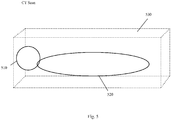
- Figure 5 illustrates a CT scan.
- the object to be scanned is made up of torso 520 and head 510.
- the object may instead be a whole body, or a smaller region of a body.
- the large cuboid 530 illustrates the volume for which scan information is obtained by the CT scanner.
- the 'dataset' 530 is a series of datapoints, located in 3-Dimensions.
- Figure 5 shows a single dataset 530.
- a marker substance may be injected into a patient 520/510.
- one CT 'phase' may be taken prior to the injection
- a second 'phase' may be taken just as the injection is carried out
- a third CT 'phase' may be taken 5 seconds or so after the second phase.
- the resulting CT dataset is a multiphase dataset, with three phases each covering the same spatial extent and taken in the same direction.
- a CT scanner will take axial slices.
- Figures 6 and 7 illustrate a multi-series MRI scan.
- Object 610/620 corresponds to that in figure 5 .
- the MRI scan comprises:
- First series 642 may comprise a series of axial 2D slices, whose locations are shown by the short lines 644 along the top of the cuboid 642.
- second series 646 may comprise a series of axial 2D slices, whose locations are shown by the short lines 648 along the top of the cuboid 646.
- the third series 650 may be made up, for example, of 2D slices that are in panes parallel to any of the faces of cuboid 650. Clearly, these will not be axial slices. Angle 652 shows that cuboid 650 is tilted, and none of the faces of cuboid 650 has a normal that lies in the axial direction of object 610/620.
- Figure 7 corresponds to figure 6 .
- figure 7 shows just the three volumes, with references 742, 746 and 750, as they may be provided as an input to the method and system of the present invention.
- Label 780 shows the three components, i.e. the three volumes, of the multi-series dataset that results from the MRI scan in figure 6 .
- first volume 742 two 2D slices have been shown. These are 2D slices 760 and 762. These 2D slices are axial slices, which located at points 744 and 745, indicating parallel planes. Similar axial slices may make up second volume 746, and be located at points 748.
- the 2D slices in third series 750 may lie in planes parallel to the nearest face 772. However, the slices may lie in planes parallel to the face 770, shown to the right of volume 750. Alternatively, the 2D slices may lie in planes parallel to top face 774 of volume 750. In each of these cases, the 2D slices will not be axial.
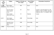
- Figure 8 and 9 show tables, each illustrating examples of three 3-D scans.
- scan 1 is a multi-series MRI scan.
- the three volumes of scan 1 are all of the head, but are taken in three orthogonal directions.
- Scan 2 is a CT scan comprising two phases, both also of the head. Both phases are taken axially, as were the 2d slices that make up the first volume of the 1 st scan.
- Scan 3 is not a multi-volume scan. It is also of the head, but is an axial PET scan.
- the plane of acquisition of, for example, any image derived from one of the MRI series can:
- Conditions (i) and (ii) will apply not only to images from one of the MRI series, but can also apply when a user selects an image from a different one of the three MRI series. If the user chooses, the images from the first and third scans can, for example, be from the same plane as the plane of acquisition of an image from one of the phases of the CT scan. So the user can select which scan will be used as a basis for selecting/ re-slicing images from the other two datasets.
- the table of figure 9 shows a more unusual set of scans than in table 8.
- the 1 st scan is a multi-series MRI dataset.
- each series is for a different part of the object.
- the different parts are three organs/regions: head; heart and pancreas. This contrasts with the table of figure 8 , where each series in the MRI dataset was for the same part of the object, but taken in an orthogonal plane to the other two series.
- the two CT phases provide 2D slices of the whole object, i.e. the whole body. So, whatever image is selected from any of the three series of the MRI multi-series, an image can be selected or re-sliced from one of the CT phases and will be in the same plane as the image from the MRI series. This is important, since the second series of the MRI multi-series dataset is taken at an angle that does not correspond to axial, coronal or saggital.
- the coverage of the 3 rd scan, the PET scan, is limited to the head. So the invention may only display three images, simultaneously, when the first series of the MRI dataset is being displayed, i.e. when the user is examining images of the head.
- the second or third series of the 1 st scan is being displayed, there is no image that can be generated of the same part of the object, from the 3 rd scan. This is because the third scan did not encompass the heart and pancreas.
- the invention introduces three new display binding types: field of view binding, orientation binding and dataset binding. Each of these is discussed below:
- the field of view determines the extent of the 3D scan, and ultimately the extent of the anatomy being viewed.
- the field of view can be manually adjusted through the zoom and pan controls.
- the field of view is directly bound to that of other views.
- the field of view for the view displaying an image from the CT dataset 530 is adjusted automatically, such that it correlates with that of the MRI image being displayed. In this manner, whatever the field of view of the particular MRI image currently being displayed in the view, the CT always stays correlated. Thus the user can easily compare the image of the CT with that of the MRI, without needing to perform manual adjustments.
- the MRI set comprises a first series covering the lung, and another set of slices of the pelvic area.
- the user would be required to re-adjust the zoom and pan of the CT view when switching between the lung and pelvic MRI series, i.e. deciding to select an image from the other series. This is time consuming.
- this is automatically adjusted, saving a great deal of time.
- the field of view is automatically synchronised on bound views, when the user changes the image being viewed in a multi-volume set.
- the orientation of the view of the image determines the orientation of the slice through the 3D volume.
- 'Dataset Driven Orientation Binding' This is referred to as 'Dataset Driven Orientation Binding'.
- the orientation for the view displaying the CT is adjusted automatically, such that it correlates with that of the MRI image being displayed. It is typical that different MRI image series from a multi-series MRI dataset will comprise images with different orientations. This capability is particularly advantageous for such multi-series MRI datasets, as it ensures that the CT is always displayed in the same orientation as the MRI.
- Orientation binding can be performed, where the user is performing a manual adjustment of the view orientation. For example, if the user has loaded several CTs taken over time to determine the change in disease as a response to treatment, the invention can keep the view consistent. Using a conventional workstation, any adjustment to the view orientation will not be synchronised, and the user must make appropriate changes manually. This may be error-prone, and time consuming.
- the invention allows the user to make comparisons easily.
- the invention provides the capability of 'binding' the dataset being examined. As a consequence, as the user switches the view between the various datasets of the first multi-volume dataset, the corresponding dataset from the second multi-volume acquisition is shown.
- the invention does not provide a binding.
- the invention may also bind curved MPR views. To do this, a deformable registration is used.
- a transformation is required that maps locations in each MR image in the set with locations in the CT.
- a transformation may be determined through the use of a registration algorithm and may be of the rigid, affine or deformable type.
- all of the MRI images in the set are acquired in the same sitting, and therefore the relationship between each of these is known.
- the user is presented with views of images from the MRI images and the CT on the display.
- Most modern workstations allow the user to configure the size and the position of the MPR views, or "hanging protocols" as they are termed in the field of medical imaging, in a manner of their choosing. For this example, consider a simple display shown in Figure 4 , where the view 410 on the left shows a slice of one of the MRI images in the multi-sequence set, and the image on the right shows a slice of the CT 3D scan.
- the invention applies control logic to the views of the data, such that the user is always shown an image from the different modalities that correspond to the same anatomical section.
- the invention may achieve this behaviour by synchronising a number of properties of the display and performs the following steps.
- Step 1) The invention allows the user to load all the data selected by the user.
- this includes the CT (or PET/CT) and all of the sequences of the MRI dataset (which can be one or more).
- Step 2 The invention allows the user to define layouts in their preferred arrangement.
- the user can pre-define the orientation of the MPR slice views, as with conventional workstations.
- the user can also define a new view type, the Acquisition View, which automatically sets the view orientation to that of the acquisition orientation of the MPR dataset being viewed.
- the orientation is automatically adjusted.
- this new view type allows the user to navigate the 3D volume while always viewing the MRI image in its optimal manner.
- the invention can account for this, and adjust the view orientation as the user navigates through the slices.
- Step 3 The invention can, at the user's preference, automatically adjust the view orientation of the CT (or PET and CT) such that they are always in the same orientation as the particular MRI image viewed in the MRI Acquisition view. As the user selects the different images within the MRI multi-sequence series, the orientation of the CT (or PET and CT) are automatically adjusted such that they are always in the same orientation.
- the invention may optimally also operate to keep the orientation of the MRI synchronised with that of the CT (or PET and CT). That is, all the bindings may be configured to operate symmetrically.
- the invention may also adjust the field of view of the CT (or PET and CT) to match that of the particular MRI image selected for viewing by the user.
- the field of view of the CT or PET and CT
- the field of view is defined by the pan and the extent of the display.
- MRI image series comprise a thoracic scan and pelvic scan
- CT panning, zoom and extent of the display are adjusted to show the same part of the anatomy as that shown in the MRI image selected by the user.
- any other parameters required to define the field of view of the display in a particular implementation may be adjusted.
- a curved MPR is an MPR slice whose normal vector follows a curve, instead of a line, through the 3D volume. In essence it is a view that adjusts the view orientation for each slice according to a pre-defined curve. This type of view may be advantageous where the clinician needs to visualise a structure that curves through the body, such as a vessel or vertebral structure, because the view orientation is always kept normal to the orientation of the structure.
- the curve is usually defined by the user or found through the application of a specific algorithm.
- the invention may be extended to bind the orientation of curved MPRs across multiple datasets. This is achieved by mapping the curve to the other datasets to be viewed using a registration - a transformation which maps locations in one dataset to locations in another. For example, a deformable registration mapping the datasets could be used for this. Given the mapped curved, each view can look-up the appropriate orientation, by calculating the normal to the curve defined on its corresponding dataset.
- the registration between the datasets may be rigid, affine or another parametric transformation, or deformable. It may be calculated by using a conventional registration algorithm, using just the images. Alternatively, an attempt can be made to map MPR curves, defined on each or some of the datasets whose views are to be bound. For example, an MPR curve can be defined by the user on each of the datasets. This may be used in full or in part to define or estimate a deformable registration between the datasets.
- Figure 10 shows a workstation 1000 for implementing a method of displaying medical images in accordance with the invention.
- Keyboard 1030, mouse 1040 and display screen 1050 facilitate communication with a user of the medical imaging workstation.
- An interactive touchscreen may be included.
- First subsystem 1010 of workstation 1000 may be implemented for example as signal processing logic and memory. First subsystem 1010 allows a user to load and store:
- Analysis module 1020 allows the creation and simultaneously displaying of medical scan images. Analysis module may:
- the first image (410) and the second image (420) may be displayed simultaneously.
- the user input means 1030, 1040 allow the selection of medical scan images for display, and allow the user to decide which medical scan image(s) to display at a given time.
- FIG 11 shows a hybrid scanner 1100 in accordance with the invention.
- Hybrid scanner 1100 has some analogous components to those described in figure 10 for a medical imaging workstation 1000.
- Keyboard 1130, mouse 1140 and screen 1150 facilitate communication with a user of the hybrid scanner 1100.
- Hybrid scanner 1100 comprises:
- a computer program product in accordance with the invention has executable code for a method in accordance with the invention.
- the method may create and simultaneously display medical scan images, from each of:
- Figure 12 illustrates an embodiment of a method in accordance with the invention.
- the method of the invention allows the creation and simultaneously display of medical scan images, from each of:
- a second image (420) is obtained from the second medical scan dataset (530), the second image lying in the first plane.
- the first image (410) and the second image (420) are displayed simultaneously.
- step 6 further images from the second volume of the first dataset may be displayed, with corresponding images from the second dataset.
- the user may choose another volume of the first dataset, including re-selecting the first volume, and select images from there.
- the second image may be obtained, for example by re-slicing, once the user has chosen the first image for display from the first dataset. This may involve a delay, for re-slicing the second dataset.
- the invention may comprise a step of ascertaining which acquisition views are included in the first dataset, i.e. the planes in which each slice of the first dataset lie. This step may comprise ascertaining which acquisition views/planes are included in just one volume, or in more than one volume, where the first dataset is a multi-volume dataset. For each acquisition plane of the first dataset, a corresponding image in the same plane can be derived in advance, and stored. Thus when a user selects any of images 410, 430, 450 or 470, the corresponding image 420, 440, 460, 480 may then already be immediately available for display, without any delay.
- a multiseries MRI dataset may comprise ten or more different series, each having tens or hundreds of 2d slices.
- the advanced computation in such cases may be time consuming, but still practicable.
- Volume reconstruction may provide particular advantages, when an MRI dataset is to be displayed.
- An MRI dataset, or any other dataset for display may be "volume reconstructed" to create a 3D volume, from the 2D slices in the original scan.
- a 3D volume is created.
- 2D slices from the scan are populated into the 3D volume.
- the size of voxels in the volume will correspond to the spatial extent covered by each datapoint of each 2D slice.
- the slice thickness in the 3D volume corresponds to the slice thickness of the 2D scan slices that were acquired in the scan.
- Volume reconstruction of the dataset may speed the re-slicing and other manipulation of the original scan datapoints, for display.
- the invention may also provide methods of:
- the method may allow the creation and simultaneous displaying of medical scan images, from each of:
- the method further comprises displaying a first image (410) derived from the first volume (710) of the first dataset (780), the extent of the first image comprising a field of view derived from the first volume, and displaying a second image (420), obtained from the second dataset (530), together with the first image, an extent of the second image being locked to the field of view.
- the field of view may be the full field of view of the first volume.
- the method may comprise: displaying a third image (770) derived from the second volume (750) of the first dataset (780), an extent of the third image comprising a second field of view derived from the second volume; and displaying a fourth image (780), obtained from the second dataset (530), together with the third image (770), an extent of the fourth image (780) being locked to the second field of view.
- the second field of view may be the full field of view of the second volume.
- the method may allow creating and simultaneously displaying medical scan images, from each of:
- the method further comprises choosing a volume of the first dataset (780), and binding the selection of the volume of the second dataset (530) to the chosen volume of the first dataset, whereby, when displaying a first image (410) from a first volume (710) of the first multi-volume medical scan dataset, an image will be displayed from a volume of the second dataset that corresponds to the first volume (710).
- the method may allow creating and simultaneously displaying medical scan images, from each of:
- the method further comprises obtaining input from a user regarding an orientation for a view of a displayed first image, derived from the first (780) dataset, and binding together the orientation for the first image (410) and at least a second image (420) obtained from the second (530) dataset, the first (410) and second (420) images being displayed together, whereby, as a user adjusts the orientation of the view of either image, the orientation of the other image (410, 420) is adjusted automatically, such that the orientation of the displayed image (420, 440) from the second dataset (530) corresponds to the orientation of the displayed image (410, 430) from the first dataset (780) .
- the acquisition plane of each slice 644, 648 may be spaced from neighbouring acquisition planes by a distance at least twice as great as the distance between datapoints within the slices.
- the present invention may be used in, for example:
Landscapes
- Life Sciences & Earth Sciences (AREA)
- Engineering & Computer Science (AREA)
- Health & Medical Sciences (AREA)
- Medical Informatics (AREA)
- Pathology (AREA)
- Heart & Thoracic Surgery (AREA)
- High Energy & Nuclear Physics (AREA)
- Physics & Mathematics (AREA)
- Nuclear Medicine, Radiotherapy & Molecular Imaging (AREA)
- Optics & Photonics (AREA)
- Veterinary Medicine (AREA)
- Radiology & Medical Imaging (AREA)
- Biomedical Technology (AREA)
- Biophysics (AREA)
- Molecular Biology (AREA)
- Surgery (AREA)
- Animal Behavior & Ethology (AREA)
- General Health & Medical Sciences (AREA)
- Public Health (AREA)
- Computer Vision & Pattern Recognition (AREA)
- Human Computer Interaction (AREA)
- Magnetic Resonance Imaging Apparatus (AREA)
- Apparatus For Radiation Diagnosis (AREA)
Claims (13)
- Verfahren zum Erzeugen und gleichzeitigen Anzeigen medizinischer Scanbilder aus sowohl(i) einem ersten (780) medizinischen Scandatensatz, der durch Scannen eines 3-dimensionalen (3-D) Objektes mit einer ersten Scanmodalität erhalten wird; als auch(ii) einem zweiten (530) medizinischen Scandatensatz, der durch Scannen des 3-dimensionalen (3-D) Objekts mit einer zweiten Scanmodalität erhalten wird;wobei der erste (780) und der zweite (530) medizinische Scandatensatz 3-dimensionale (3-D) Datensätze sind; und
wobei wenigstens der erste medizinische Scandatensatz (780) ein Mehrfachvolumendatensatz ist, der wenigstens ein erstes Volumen (710) und ein zweites Volumen (750) umfasst;
wobei das Verfahren umfasst:Ableiten eines ersten Bilds (410) aus einer Volumenrekonstruktion des ersten Volumens (710) des ersten (780) medizinischen Scandatensatzes, wobei die Sichtorientierung automatisch eingestellt wird, so dass das erste Bild in einer ersten Ebene liegt, wobei die erste Ebene einer Erfassungsebene des ersten Volumens (710) des ersten (780) medizinischen Scandatensatzes entspricht;Erhalten eines zweiten Bilds (420) aus einer Volumenrekonstruktion des zweiten medizinischen Scandatensatzes (530), wobei die Sichtorientierung automatisch eingestellt wird, so dass das zweite Bild in der ersten Ebene liegt; undgleichzeitiges Anzeigen des ersten Bilds (410) und des zweiten Bilds (420),wobei das Verfahren weiterhin in Reaktion darauf, dass ein Nutzer auswählt, ein weiteres Bild aus dem zweiten Volumen (750) des ersten (780) medizinischen Scandatensatzes anzuzeigen, umfasst:Ableiten eines dritten Bilds (470) aus einer Volumenrekonstruktion des zweiten Volumens (750) des ersten Datensatzes (780), wobei die Sichtorientierung automatisch eingestellt wird, so dass das dritte Bild in einer zweiten Ebene liegt, wobei die zweite Ebene einer Erfassungsebene des zweiten Volumens (750) des ersten medizinischen Scandatensatzes (780) entspricht;Erhalten eines vierten Bilds (480) aus einer Volumenrekonstruktion des zweiten Datensatzes (530), wobei die Sichtorientierung automatisch eingestellt wird, so dass das vierte Bild in der zweiten Ebene liegt; undgleichzeitiges Anzeigen des dritten Bilds (470) und des vierten Bilds (480). - Verfahren nach Anspruch 1, weiterhin umfassend:
Erhalten des zweiten Bilds (420) durch Neuschneiden des zweiten (530) medizinischen Scandatensatzes, um ein Bild abzuleiten, das Datenpunkte aus dem zweiten (530) medizinischen Scandatensatz umfasst, die in der ersten Ebene liegen. - Verfahren nach Anspruch 1, weiterhin umfassend:
Erhalten des vierten Bilds (480) durch Neuschneiden des zweiten (530) medizinsichen Scandatensatzes, um ein Bild abzuleiten, das Datenpunkte aus dem zweiten (530) medizinischen Scandatensatz umfasst, die in der zweiten Ebene liegen. - Verfahren nach Anspruch 1, weiterhin umfassend:Ausführen einer Volumenrekonstruktion von sowohl dem ersten (780) als auch dem zweiten (530) Datensatz; undErhalten einer Transformation, die Datenpunkte des ersten (780) medizinischen Scandatensatzes in Deckung mit Datenpunkten des zweiten (530) medizinischen Scandatensatzes abbildet.
- Verfahren nach Anspruch 1, weiterhin umfassend:Ausführen einer Volumenrekonstruktion aller Datenpunkte des zweiten Datensatzes (530);zu einem Zeitpunkt vor dem Ableiten des ersten Bilds (410), Ausführen einer Volumenrekonstruktion von Datenpunkten des ersten Volumens (710) des ersten Datensatzes (780) und erhalten einer Transformation, die Datenpunkte des ersten Volumens (710) des ersten (780) Datensatzes in Deckung mit den Datenpunkten des zweiten (530) Datensatzes abbildet; undzu einem Zeitpunkt vor dem Ableiten des dritten Bilds (470), Ausführen einer Volumenrekonstruktion von Datenpunkten des zweiten Volumens (750) des ersten Datensatzes (780) und erhalten einer Transformation, die Datenpunkte des zweiten Volumens (710) des ersten (780) Datensatzes in Deckung mit den Datenpunkten des zweiten (530) Datensatzes abbildet.
- Verfahren nach Anspruch 1, weiterhin umfassend:
Anzeigen des ersten (410) und des zweiten (420) Bilds in nebeneinander angeordneter Ansicht. - Verfahren nach Anspruch 1, weiterhin umfassend:Erhalten eines fünften Bilds und eines sechsten Bilds aus einem dritten medizinischen 3-D-Scandatensatz, wobei das fünfte Bild in der ersten Ebene und das sechste Bild in der zweiten Ebene sind; undAnzeigen des fünften Bilds gleichzeitig mit dem ersten (410) und dem zweiten (420) Bild; undAnzeigen des sechsten Bilds gleichzeitig mit dem dritten (470) und dem vierten (480) Bild.
- Verfahren nach Anspruch 1, wobei:der erste Datensatz (780) ein Mehrfachsequenz-MRT-Datensatz ist;der zweite Datensatz (530) ein CT-Datensatz ist;die erste und die zweite Ebene nicht parallele Erfassungsebenen sind.
- Verfahren nach Anspruch 1, wobei:
ein Gesichtsfeld des zweiten Bilds (420) wenigstens anfänglich darauf beschränkt ist, einem Gesichtsfeld des ersten Bilds (410) zu entsprechen. - Verfahren nach Anspruch 1, wobei:ein Gesichtsfeld des zweiten Bilds (420) wenigstens anfänglich darauf beschränkt ist, einem Gesichtsfeld des ersten Bilds (410) zu entsprechen; undein Gesichtsfeld des vierten Bilds (480) wenigstens anfänglich darauf beschränkt ist, einem Gesichtsfeld des dritten Bilds (470) zu entsprechen.
- Verfahren nach Anspruch 1, wobei:der zweite Datensatz ein medizinischer 3-D-Mehrfachvolumen-Datensatz ist;das zweite Bild (420) aus einem ersten Volumen des zweiten Datensatzes erhalten wird, wobei das erste Volumen des zweiten Datensatzes denselben Teil des gescannten Objekts enthält, wie das erste Volumen (710) des ersten Datensatzes (780); unddas vierte Bild (480) aus einem zweiten Volumen des zweiten Datensatzes erhalten wird, wobei das zweite Volumen des zweiten Datensatzes denselben Teil des gescannten Objekts enthält, wie das zweite Volumen (750) des ersten Datensatzes (780).
- Medizinischer Hybrid-Bildgebungsscanner (1100), umfassend:ein Steuermodul (1160), wobei das Steuermodul betreibbar ist, um eine Scaneinheit so zu steuern, dass ein erster medizinischer Scandatensatz und ein zweiter medizinischer Scandatensatz erhalten werden, wobei der erste medizinische Scandatensatz aus einem Scannen eines 3-dimensionalen (3-D) Objekts mit einem ersten Scanmodus resultiert wird und das zweite medizinische Scannen aus einem Scannen des Objekts mit einem zweiten Scanmodus resultiert;wobei der erste (780) und der zweite (530) medizinische Scandatensatz 3-dimensionale (3-D) Datensätze sind; undwenigstens der erste medizinische Scandatensatz (780) ein Mehrfachvolumendatensatz ist, der wenigstens ein erstes Volumen (710) und ein zweites Volumen (750) umfasst; undein Analysemodul (1120), wobei das Analysemodul betreibbar ist zum:Ableiten eines ersten Bilds (410) aus einer Volumenrekonstruktion des ersten (780) medizinischen Scandatensatzes, wobei die Sichtorientierung automatisch eingestellt wird, so dass das erste Bild in einer ersten Ebene liegt, wobei die erste Ebene einer Erfassungsebene des ersten (780) medizinischen Scandatensatzes entspricht;Erhalten eines zweiten Bilds (420) aus einer Volumenrekonstruktion des zweiten medizinischen Scandatensatzes (530), wobei die Sichtorientierung automatisch eingestellt wird, so dass das zweite Bild in der ersten Ebene liegt; undeine Anzeige (1150), die betreibbar ist, um das erste Bild (410) und das zweite Bild (420) gleichzeitig anzuzeigen,wobei das Analysemodul (1120) weiterhin in Reaktion darauf, dass der Nutzer auswählt, ein weiteres Bild aus dem zweiten Volumen (710) des ersten (780) medizinischen Scandatensatzes auszuwählen, betreibbar ist zum:Ableiten eines dritten Bilds (470) aus einer Volumenrekonstruktion des zweiten Volumens (750) des ersten Datensatzes (780), wobei die Sichtorientierung automatisch eingestellt wird, so dass das dritte Bild in einer zweiten Ebene liegt, wobei die zweite Ebene einer Erfassungsebene des zweiten Volumens (750) entspricht;Erhalten eines vierten Bilds (480) aus einer Volumenrekonstruktion des zweiten Datensatzes (530), wobei die Sichtorientierung automatisch eingestellt wird, so dass das vierte Bild in der zweiten Ebene liegt; undgleichzeitiges Anzeigen des dritten Bilds (470) und des vierten Bilds (480).
- Medizinischer Hybrid-Bildgebungsscanner (1100) nach Anspruch 12, der weiterhin Nutzerschnittstellenmittel (1130, 1140) umfasst, wobei die Nutzerschnittstellenmittel betreibbar sind zum:Präsentieren wenigstens der folgenden Optionen der Bildanzeigeorientierung für einen Nutzer: axial; koronal; sagittal; Erfassung; undwenn ein Nutzer die Erfassungsoption auswählt, Veranlassen einer Anzeige des ersten Bilds (410) und des zweiten Bilds (420) in der Ebene, in der das erste Bild erfasst wurde.
Applications Claiming Priority (1)
| Application Number | Priority Date | Filing Date | Title |
|---|---|---|---|
| US13/304,512 US10105115B2 (en) | 2011-11-25 | 2011-11-25 | Method and system for processing medical image datasets |
Publications (2)
| Publication Number | Publication Date |
|---|---|
| EP2596749A1 EP2596749A1 (de) | 2013-05-29 |
| EP2596749B1 true EP2596749B1 (de) | 2018-09-05 |
Family
ID=47500901
Family Applications (1)
| Application Number | Title | Priority Date | Filing Date |
|---|---|---|---|
| EP12194063.9A Active EP2596749B1 (de) | 2011-11-25 | 2012-11-23 | Verfahren und System zur Verarbeitung von medizinischen Bilderdatensätzen |
Country Status (2)
| Country | Link |
|---|---|
| US (1) | US10105115B2 (de) |
| EP (1) | EP2596749B1 (de) |
Families Citing this family (12)
| Publication number | Priority date | Publication date | Assignee | Title |
|---|---|---|---|---|
| KR20130080311A (ko) * | 2012-01-04 | 2013-07-12 | 삼성메디슨 주식회사 | 의료 영상 표시 방법 및 의료 영상 표시 장치 |
| US9196091B2 (en) * | 2012-01-24 | 2015-11-24 | Kabushiki Kaisha Toshiba | Image processing method and system |
| US10395420B2 (en) * | 2012-02-28 | 2019-08-27 | Brainlab Ag | Calculation of a medical image using templates |
| CN103544688B (zh) * | 2012-07-11 | 2018-06-29 | 东芝医疗系统株式会社 | 医用图像融合装置和方法 |
| US9147280B2 (en) * | 2012-08-03 | 2015-09-29 | Kabushiki Kaisha Toshiba | Preparation and display of derived series of medical images |
| US9256965B2 (en) * | 2013-01-30 | 2016-02-09 | Impac Medical Systems, Inc. | Method and apparatus for generating a derived image using images of different types |
| US9460510B2 (en) * | 2013-03-29 | 2016-10-04 | Siemens Medical Solutions Usa, Inc. | Synchronized navigation of medical images |
| US10716626B2 (en) * | 2015-06-24 | 2020-07-21 | Edda Technology, Inc. | Method and system for interactive 3D scope placement and measurements for kidney stone removal procedure |
| JP6823646B2 (ja) * | 2015-09-02 | 2021-02-03 | ベンタナ メディカル システムズ, インコーポレイテッド | 生体試料の複数の画像を表示するための画像処理システムおよび方法 |
| CN110558999B (zh) * | 2019-08-05 | 2023-05-30 | 上海联影医疗科技股份有限公司 | 扫描成像方法、装置和系统 |
| US12073538B2 (en) * | 2021-04-08 | 2024-08-27 | Canon Medical Systems Corporation | Neural network for improved performance of medical imaging systems |
| US12462335B2 (en) | 2022-03-03 | 2025-11-04 | Rensselaer Polytechnic Institute | Systems and methods for multi-modal multi-dimensional image registration |
Family Cites Families (4)
| Publication number | Priority date | Publication date | Assignee | Title |
|---|---|---|---|---|
| US6765566B1 (en) * | 1998-12-22 | 2004-07-20 | Che-Chih Tsao | Method and apparatus for displaying volumetric 3D images |
| GB2382509B (en) * | 2001-11-23 | 2003-10-08 | Voxar Ltd | Handling of image data created by manipulation of image data sets |
| US7822254B2 (en) * | 2006-04-21 | 2010-10-26 | Siemens Medical Solutions Usa, Inc. | Automatic positioning of matching multi-planar image reformatting (MPR) views of multiple 3D medical images |
| JP5629582B2 (ja) * | 2007-12-13 | 2014-11-19 | コーニンクレッカ フィリップス エヌ ヴェ | 医療画像データの組からデータを検索する方法、システム及びコンピュータ・プログラム |
-
2011
- 2011-11-25 US US13/304,512 patent/US10105115B2/en active Active
-
2012
- 2012-11-23 EP EP12194063.9A patent/EP2596749B1/de active Active
Also Published As
| Publication number | Publication date |
|---|---|
| US20130135287A1 (en) | 2013-05-30 |
| US10105115B2 (en) | 2018-10-23 |
| EP2596749A1 (de) | 2013-05-29 |
Similar Documents
| Publication | Publication Date | Title |
|---|---|---|
| US10105115B2 (en) | Method and system for processing medical image datasets | |
| US7916915B2 (en) | Image handling and display in x-ray mammography and tomosynthesis | |
| CN103295256B (zh) | 医用图像处理装置以及医用图像处理程序 | |
| CN103765475B (zh) | 具有对最优断层摄影切片的自动选择的交互式实况分割 | |
| KR102109588B1 (ko) | 유방 조직 이미지를 프로세싱하고, 디스플레잉하고, 네비게이팅하기 위한 방법 | |
| US7751605B2 (en) | Method and device for visualizing a sequence of tomographic image data records | |
| US9361726B2 (en) | Medical image diagnostic apparatus, medical image processing apparatus, and methods therefor | |
| US10339710B2 (en) | Medical image system and method | |
| EP3569152A1 (de) | Bildverarbeitung und bildanzeige in der digitalen mammographie | |
| US20140205167A1 (en) | Method for interactive manual matching and real-time projection calculation in imaging | |
| US9741124B2 (en) | Method and system of defining a region of interest on medical scan images | |
| WO2014145452A1 (en) | Enhancements for displaying and viewing tomosynthesis images | |
| JP2014030693A (ja) | 画像処理装置、医用画像診断装置、画像処理方法、及び画像処理プログラム | |
| CN102665555A (zh) | 生成合成医学图像 | |
| Ratib | PET/CT image navigation and communication | |
| Beck et al. | Augmented reality and virtual reality: Initial successes in diagnostic radiology | |
| JP5194138B2 (ja) | 画像診断支援装置およびその動作方法、並びに画像診断支援プログラム | |
| Zhang et al. | Dynamic real-time 4D cardiac MDCT image display using GPU-accelerated volume rendering | |
| US20080074427A1 (en) | Method for display of medical 3d image data on a monitor | |
| Kita et al. | A CAD system for the 3D location of lesions in mammograms | |
| EP3423968B1 (de) | Navigationssystem für medizinisches bild | |
| JP6896145B2 (ja) | 画像処理装置、画像処理方法、および画像処理プログラム | |
| JP2014000124A (ja) | 医用画像処理装置及び医用画像処理方法 |
Legal Events
| Date | Code | Title | Description |
|---|---|---|---|
| PUAI | Public reference made under article 153(3) epc to a published international application that has entered the european phase |
Free format text: ORIGINAL CODE: 0009012 |
|
| AK | Designated contracting states |
Kind code of ref document: A1 Designated state(s): AL AT BE BG CH CY CZ DE DK EE ES FI FR GB GR HR HU IE IS IT LI LT LU LV MC MK MT NL NO PL PT RO RS SE SI SK SM TR |
|
| AX | Request for extension of the european patent |
Extension state: BA ME |
|
| 17P | Request for examination filed |
Effective date: 20131129 |
|
| RBV | Designated contracting states (corrected) |
Designated state(s): AL AT BE BG CH CY CZ DE DK EE ES FI FR GB GR HR HU IE IS IT LI LT LU LV MC MK MT NL NO PL PT RO RS SE SI SK SM TR |
|
| RIN1 | Information on inventor provided before grant (corrected) |
Inventor name: MCCABE, DAVID Inventor name: RODRIGUES, EDUARDO Inventor name: KADIR, TIMOR |
|
| 17Q | First examination report despatched |
Effective date: 20140306 |
|
| RIC1 | Information provided on ipc code assigned before grant |
Ipc: A61B 6/00 20060101AFI20180322BHEP Ipc: G06T 7/00 20060101ALN20180322BHEP Ipc: A61B 6/03 20060101ALI20180322BHEP |
|
| GRAP | Despatch of communication of intention to grant a patent |
Free format text: ORIGINAL CODE: EPIDOSNIGR1 |
|
| INTG | Intention to grant announced |
Effective date: 20180509 |
|
| GRAS | Grant fee paid |
Free format text: ORIGINAL CODE: EPIDOSNIGR3 |
|
| GRAA | (expected) grant |
Free format text: ORIGINAL CODE: 0009210 |
|
| AK | Designated contracting states |
Kind code of ref document: B1 Designated state(s): AL AT BE BG CH CY CZ DE DK EE ES FI FR GB GR HR HU IE IS IT LI LT LU LV MC MK MT NL NO PL PT RO RS SE SI SK SM TR |
|
| REG | Reference to a national code |
Ref country code: GB Ref legal event code: FG4D |
|
| REG | Reference to a national code |
Ref country code: CH Ref legal event code: EP |
|
| REG | Reference to a national code |
Ref country code: AT Ref legal event code: REF Ref document number: 1036886 Country of ref document: AT Kind code of ref document: T Effective date: 20180915 |
|
| REG | Reference to a national code |
Ref country code: IE Ref legal event code: FG4D |
|
| REG | Reference to a national code |
Ref country code: DE Ref legal event code: R096 Ref document number: 602012050602 Country of ref document: DE |
|
| REG | Reference to a national code |
Ref country code: NL Ref legal event code: FP |
|
| REG | Reference to a national code |
Ref country code: LT Ref legal event code: MG4D |
|
| PG25 | Lapsed in a contracting state [announced via postgrant information from national office to epo] |
Ref country code: LT Free format text: LAPSE BECAUSE OF FAILURE TO SUBMIT A TRANSLATION OF THE DESCRIPTION OR TO PAY THE FEE WITHIN THE PRESCRIBED TIME-LIMIT Effective date: 20180905 Ref country code: BG Free format text: LAPSE BECAUSE OF FAILURE TO SUBMIT A TRANSLATION OF THE DESCRIPTION OR TO PAY THE FEE WITHIN THE PRESCRIBED TIME-LIMIT Effective date: 20181205 Ref country code: SE Free format text: LAPSE BECAUSE OF FAILURE TO SUBMIT A TRANSLATION OF THE DESCRIPTION OR TO PAY THE FEE WITHIN THE PRESCRIBED TIME-LIMIT Effective date: 20180905 Ref country code: GR Free format text: LAPSE BECAUSE OF FAILURE TO SUBMIT A TRANSLATION OF THE DESCRIPTION OR TO PAY THE FEE WITHIN THE PRESCRIBED TIME-LIMIT Effective date: 20181206 Ref country code: FI Free format text: LAPSE BECAUSE OF FAILURE TO SUBMIT A TRANSLATION OF THE DESCRIPTION OR TO PAY THE FEE WITHIN THE PRESCRIBED TIME-LIMIT Effective date: 20180905 Ref country code: RS Free format text: LAPSE BECAUSE OF FAILURE TO SUBMIT A TRANSLATION OF THE DESCRIPTION OR TO PAY THE FEE WITHIN THE PRESCRIBED TIME-LIMIT Effective date: 20180905 Ref country code: NO Free format text: LAPSE BECAUSE OF FAILURE TO SUBMIT A TRANSLATION OF THE DESCRIPTION OR TO PAY THE FEE WITHIN THE PRESCRIBED TIME-LIMIT Effective date: 20181205 |
|
| REG | Reference to a national code |
Ref country code: AT Ref legal event code: MK05 Ref document number: 1036886 Country of ref document: AT Kind code of ref document: T Effective date: 20180905 |
|
| PG25 | Lapsed in a contracting state [announced via postgrant information from national office to epo] |
Ref country code: HR Free format text: LAPSE BECAUSE OF FAILURE TO SUBMIT A TRANSLATION OF THE DESCRIPTION OR TO PAY THE FEE WITHIN THE PRESCRIBED TIME-LIMIT Effective date: 20180905 Ref country code: LV Free format text: LAPSE BECAUSE OF FAILURE TO SUBMIT A TRANSLATION OF THE DESCRIPTION OR TO PAY THE FEE WITHIN THE PRESCRIBED TIME-LIMIT Effective date: 20180905 Ref country code: AL Free format text: LAPSE BECAUSE OF FAILURE TO SUBMIT A TRANSLATION OF THE DESCRIPTION OR TO PAY THE FEE WITHIN THE PRESCRIBED TIME-LIMIT Effective date: 20180905 |
|
| PG25 | Lapsed in a contracting state [announced via postgrant information from national office to epo] |
Ref country code: RO Free format text: LAPSE BECAUSE OF FAILURE TO SUBMIT A TRANSLATION OF THE DESCRIPTION OR TO PAY THE FEE WITHIN THE PRESCRIBED TIME-LIMIT Effective date: 20180905 Ref country code: CZ Free format text: LAPSE BECAUSE OF FAILURE TO SUBMIT A TRANSLATION OF THE DESCRIPTION OR TO PAY THE FEE WITHIN THE PRESCRIBED TIME-LIMIT Effective date: 20180905 Ref country code: ES Free format text: LAPSE BECAUSE OF FAILURE TO SUBMIT A TRANSLATION OF THE DESCRIPTION OR TO PAY THE FEE WITHIN THE PRESCRIBED TIME-LIMIT Effective date: 20180905 Ref country code: PL Free format text: LAPSE BECAUSE OF FAILURE TO SUBMIT A TRANSLATION OF THE DESCRIPTION OR TO PAY THE FEE WITHIN THE PRESCRIBED TIME-LIMIT Effective date: 20180905 Ref country code: IS Free format text: LAPSE BECAUSE OF FAILURE TO SUBMIT A TRANSLATION OF THE DESCRIPTION OR TO PAY THE FEE WITHIN THE PRESCRIBED TIME-LIMIT Effective date: 20190105 Ref country code: AT Free format text: LAPSE BECAUSE OF FAILURE TO SUBMIT A TRANSLATION OF THE DESCRIPTION OR TO PAY THE FEE WITHIN THE PRESCRIBED TIME-LIMIT Effective date: 20180905 Ref country code: IT Free format text: LAPSE BECAUSE OF FAILURE TO SUBMIT A TRANSLATION OF THE DESCRIPTION OR TO PAY THE FEE WITHIN THE PRESCRIBED TIME-LIMIT Effective date: 20180905 Ref country code: EE Free format text: LAPSE BECAUSE OF FAILURE TO SUBMIT A TRANSLATION OF THE DESCRIPTION OR TO PAY THE FEE WITHIN THE PRESCRIBED TIME-LIMIT Effective date: 20180905 |
|
| PG25 | Lapsed in a contracting state [announced via postgrant information from national office to epo] |
Ref country code: SM Free format text: LAPSE BECAUSE OF FAILURE TO SUBMIT A TRANSLATION OF THE DESCRIPTION OR TO PAY THE FEE WITHIN THE PRESCRIBED TIME-LIMIT Effective date: 20180905 Ref country code: SK Free format text: LAPSE BECAUSE OF FAILURE TO SUBMIT A TRANSLATION OF THE DESCRIPTION OR TO PAY THE FEE WITHIN THE PRESCRIBED TIME-LIMIT Effective date: 20180905 Ref country code: PT Free format text: LAPSE BECAUSE OF FAILURE TO SUBMIT A TRANSLATION OF THE DESCRIPTION OR TO PAY THE FEE WITHIN THE PRESCRIBED TIME-LIMIT Effective date: 20190105 |
|
| REG | Reference to a national code |
Ref country code: DE Ref legal event code: R097 Ref document number: 602012050602 Country of ref document: DE |
|
| REG | Reference to a national code |
Ref country code: CH Ref legal event code: PL |
|
| PLBE | No opposition filed within time limit |
Free format text: ORIGINAL CODE: 0009261 |
|
| STAA | Information on the status of an ep patent application or granted ep patent |
Free format text: STATUS: NO OPPOSITION FILED WITHIN TIME LIMIT |
|
| PG25 | Lapsed in a contracting state [announced via postgrant information from national office to epo] |
Ref country code: DK Free format text: LAPSE BECAUSE OF FAILURE TO SUBMIT A TRANSLATION OF THE DESCRIPTION OR TO PAY THE FEE WITHIN THE PRESCRIBED TIME-LIMIT Effective date: 20180905 Ref country code: LU Free format text: LAPSE BECAUSE OF NON-PAYMENT OF DUE FEES Effective date: 20181123 Ref country code: MC Free format text: LAPSE BECAUSE OF FAILURE TO SUBMIT A TRANSLATION OF THE DESCRIPTION OR TO PAY THE FEE WITHIN THE PRESCRIBED TIME-LIMIT Effective date: 20180905 |
|
| 26N | No opposition filed |
Effective date: 20190606 |
|
| REG | Reference to a national code |
Ref country code: BE Ref legal event code: MM Effective date: 20181130 |
|
| REG | Reference to a national code |
Ref country code: IE Ref legal event code: MM4A |
|
| PG25 | Lapsed in a contracting state [announced via postgrant information from national office to epo] |
Ref country code: CH Free format text: LAPSE BECAUSE OF NON-PAYMENT OF DUE FEES Effective date: 20181130 Ref country code: LI Free format text: LAPSE BECAUSE OF NON-PAYMENT OF DUE FEES Effective date: 20181130 Ref country code: SI Free format text: LAPSE BECAUSE OF FAILURE TO SUBMIT A TRANSLATION OF THE DESCRIPTION OR TO PAY THE FEE WITHIN THE PRESCRIBED TIME-LIMIT Effective date: 20180905 |
|
| PG25 | Lapsed in a contracting state [announced via postgrant information from national office to epo] |
Ref country code: IE Free format text: LAPSE BECAUSE OF NON-PAYMENT OF DUE FEES Effective date: 20181123 |
|
| PG25 | Lapsed in a contracting state [announced via postgrant information from national office to epo] |
Ref country code: BE Free format text: LAPSE BECAUSE OF NON-PAYMENT OF DUE FEES Effective date: 20181130 |
|
| PG25 | Lapsed in a contracting state [announced via postgrant information from national office to epo] |
Ref country code: MT Free format text: LAPSE BECAUSE OF NON-PAYMENT OF DUE FEES Effective date: 20181123 |
|
| PG25 | Lapsed in a contracting state [announced via postgrant information from national office to epo] |
Ref country code: TR Free format text: LAPSE BECAUSE OF FAILURE TO SUBMIT A TRANSLATION OF THE DESCRIPTION OR TO PAY THE FEE WITHIN THE PRESCRIBED TIME-LIMIT Effective date: 20180905 |
|
| PG25 | Lapsed in a contracting state [announced via postgrant information from national office to epo] |
Ref country code: CY Free format text: LAPSE BECAUSE OF FAILURE TO SUBMIT A TRANSLATION OF THE DESCRIPTION OR TO PAY THE FEE WITHIN THE PRESCRIBED TIME-LIMIT Effective date: 20180905 Ref country code: HU Free format text: LAPSE BECAUSE OF FAILURE TO SUBMIT A TRANSLATION OF THE DESCRIPTION OR TO PAY THE FEE WITHIN THE PRESCRIBED TIME-LIMIT; INVALID AB INITIO Effective date: 20121123 Ref country code: MK Free format text: LAPSE BECAUSE OF NON-PAYMENT OF DUE FEES Effective date: 20180905 |
|
| P01 | Opt-out of the competence of the unified patent court (upc) registered |
Effective date: 20230525 |
|
| PGFP | Annual fee paid to national office [announced via postgrant information from national office to epo] |
Ref country code: NL Payment date: 20251022 Year of fee payment: 14 |
|
| PGFP | Annual fee paid to national office [announced via postgrant information from national office to epo] |
Ref country code: DE Payment date: 20251022 Year of fee payment: 14 |
|
| PGFP | Annual fee paid to national office [announced via postgrant information from national office to epo] |
Ref country code: GB Payment date: 20251023 Year of fee payment: 14 |
|
| PGFP | Annual fee paid to national office [announced via postgrant information from national office to epo] |
Ref country code: FR Payment date: 20251022 Year of fee payment: 14 |
|
| REG | Reference to a national code |
Ref country code: DE Ref legal event code: R082 Ref document number: 602012050602 Country of ref document: DE Representative=s name: PUSCHMANN BORCHERT KAISER KLETTNER PATENTANWAE, DE Ref country code: DE Ref legal event code: R082 Ref document number: 602012050602 Country of ref document: DE Representative=s name: PATCARE PATENTANWAELTE PARTNERSCHAFT MBB, DE |