EP2595380B1 - Balayage de cartes de signification multiniveau - Google Patents
Balayage de cartes de signification multiniveau Download PDFInfo
- Publication number
- EP2595380B1 EP2595380B1 EP12164134.4A EP12164134A EP2595380B1 EP 2595380 B1 EP2595380 B1 EP 2595380B1 EP 12164134 A EP12164134 A EP 12164134A EP 2595380 B1 EP2595380 B1 EP 2595380B1
- Authority
- EP
- European Patent Office
- Prior art keywords
- coefficient
- significant
- group
- flag
- flags
- Prior art date
- Legal status (The legal status is an assumption and is not a legal conclusion. Google has not performed a legal analysis and makes no representation as to the accuracy of the status listed.)
- Active
Links
Images


Classifications
-
- H—ELECTRICITY
- H04—ELECTRIC COMMUNICATION TECHNIQUE
- H04N—PICTORIAL COMMUNICATION, e.g. TELEVISION
- H04N19/00—Methods or arrangements for coding, decoding, compressing or decompressing digital video signals
- H04N19/10—Methods or arrangements for coding, decoding, compressing or decompressing digital video signals using adaptive coding
- H04N19/102—Methods or arrangements for coding, decoding, compressing or decompressing digital video signals using adaptive coding characterised by the element, parameter or selection affected or controlled by the adaptive coding
- H04N19/132—Sampling, masking or truncation of coding units, e.g. adaptive resampling, frame skipping, frame interpolation or high-frequency transform coefficient masking
-
- H—ELECTRICITY
- H04—ELECTRIC COMMUNICATION TECHNIQUE
- H04N—PICTORIAL COMMUNICATION, e.g. TELEVISION
- H04N19/00—Methods or arrangements for coding, decoding, compressing or decompressing digital video signals
- H04N19/10—Methods or arrangements for coding, decoding, compressing or decompressing digital video signals using adaptive coding
- H04N19/102—Methods or arrangements for coding, decoding, compressing or decompressing digital video signals using adaptive coding characterised by the element, parameter or selection affected or controlled by the adaptive coding
- H04N19/129—Scanning of coding units, e.g. zig-zag scan of transform coefficients or flexible macroblock ordering [FMO]
-
- H—ELECTRICITY
- H04—ELECTRIC COMMUNICATION TECHNIQUE
- H04N—PICTORIAL COMMUNICATION, e.g. TELEVISION
- H04N19/00—Methods or arrangements for coding, decoding, compressing or decompressing digital video signals
- H04N19/10—Methods or arrangements for coding, decoding, compressing or decompressing digital video signals using adaptive coding
- H04N19/102—Methods or arrangements for coding, decoding, compressing or decompressing digital video signals using adaptive coding characterised by the element, parameter or selection affected or controlled by the adaptive coding
- H04N19/13—Adaptive entropy coding, e.g. adaptive variable length coding [AVLC] or context adaptive binary arithmetic coding [CABAC]
-
- H—ELECTRICITY
- H04—ELECTRIC COMMUNICATION TECHNIQUE
- H04N—PICTORIAL COMMUNICATION, e.g. TELEVISION
- H04N19/00—Methods or arrangements for coding, decoding, compressing or decompressing digital video signals
- H04N19/10—Methods or arrangements for coding, decoding, compressing or decompressing digital video signals using adaptive coding
- H04N19/134—Methods or arrangements for coding, decoding, compressing or decompressing digital video signals using adaptive coding characterised by the element, parameter or criterion affecting or controlling the adaptive coding
- H04N19/136—Incoming video signal characteristics or properties
-
- H—ELECTRICITY
- H04—ELECTRIC COMMUNICATION TECHNIQUE
- H04N—PICTORIAL COMMUNICATION, e.g. TELEVISION
- H04N19/00—Methods or arrangements for coding, decoding, compressing or decompressing digital video signals
- H04N19/10—Methods or arrangements for coding, decoding, compressing or decompressing digital video signals using adaptive coding
- H04N19/169—Methods or arrangements for coding, decoding, compressing or decompressing digital video signals using adaptive coding characterised by the coding unit, i.e. the structural portion or semantic portion of the video signal being the object or the subject of the adaptive coding
- H04N19/17—Methods or arrangements for coding, decoding, compressing or decompressing digital video signals using adaptive coding characterised by the coding unit, i.e. the structural portion or semantic portion of the video signal being the object or the subject of the adaptive coding the unit being an image region, e.g. an object
- H04N19/176—Methods or arrangements for coding, decoding, compressing or decompressing digital video signals using adaptive coding characterised by the coding unit, i.e. the structural portion or semantic portion of the video signal being the object or the subject of the adaptive coding the unit being an image region, e.g. an object the region being a block, e.g. a macroblock
-
- H—ELECTRICITY
- H04—ELECTRIC COMMUNICATION TECHNIQUE
- H04N—PICTORIAL COMMUNICATION, e.g. TELEVISION
- H04N19/00—Methods or arrangements for coding, decoding, compressing or decompressing digital video signals
- H04N19/10—Methods or arrangements for coding, decoding, compressing or decompressing digital video signals using adaptive coding
- H04N19/169—Methods or arrangements for coding, decoding, compressing or decompressing digital video signals using adaptive coding characterised by the coding unit, i.e. the structural portion or semantic portion of the video signal being the object or the subject of the adaptive coding
- H04N19/18—Methods or arrangements for coding, decoding, compressing or decompressing digital video signals using adaptive coding characterised by the coding unit, i.e. the structural portion or semantic portion of the video signal being the object or the subject of the adaptive coding the unit being a set of transform coefficients
-
- H—ELECTRICITY
- H04—ELECTRIC COMMUNICATION TECHNIQUE
- H04N—PICTORIAL COMMUNICATION, e.g. TELEVISION
- H04N19/00—Methods or arrangements for coding, decoding, compressing or decompressing digital video signals
- H04N19/40—Methods or arrangements for coding, decoding, compressing or decompressing digital video signals using video transcoding, i.e. partial or full decoding of a coded input stream followed by re-encoding of the decoded output stream
-
- H—ELECTRICITY
- H04—ELECTRIC COMMUNICATION TECHNIQUE
- H04N—PICTORIAL COMMUNICATION, e.g. TELEVISION
- H04N19/00—Methods or arrangements for coding, decoding, compressing or decompressing digital video signals
- H04N19/46—Embedding additional information in the video signal during the compression process
-
- H—ELECTRICITY
- H04—ELECTRIC COMMUNICATION TECHNIQUE
- H04N—PICTORIAL COMMUNICATION, e.g. TELEVISION
- H04N19/00—Methods or arrangements for coding, decoding, compressing or decompressing digital video signals
- H04N19/60—Methods or arrangements for coding, decoding, compressing or decompressing digital video signals using transform coding
- H04N19/61—Methods or arrangements for coding, decoding, compressing or decompressing digital video signals using transform coding in combination with predictive coding
-
- H—ELECTRICITY
- H04—ELECTRIC COMMUNICATION TECHNIQUE
- H04N—PICTORIAL COMMUNICATION, e.g. TELEVISION
- H04N19/00—Methods or arrangements for coding, decoding, compressing or decompressing digital video signals
- H04N19/60—Methods or arrangements for coding, decoding, compressing or decompressing digital video signals using transform coding
- H04N19/63—Methods or arrangements for coding, decoding, compressing or decompressing digital video signals using transform coding using sub-band based transform, e.g. wavelets
-
- H—ELECTRICITY
- H04—ELECTRIC COMMUNICATION TECHNIQUE
- H04N—PICTORIAL COMMUNICATION, e.g. TELEVISION
- H04N19/00—Methods or arrangements for coding, decoding, compressing or decompressing digital video signals
- H04N19/70—Methods or arrangements for coding, decoding, compressing or decompressing digital video signals characterised by syntax aspects related to video coding, e.g. related to compression standards
-
- H—ELECTRICITY
- H04—ELECTRIC COMMUNICATION TECHNIQUE
- H04N—PICTORIAL COMMUNICATION, e.g. TELEVISION
- H04N19/00—Methods or arrangements for coding, decoding, compressing or decompressing digital video signals
- H04N19/90—Methods or arrangements for coding, decoding, compressing or decompressing digital video signals using coding techniques not provided for in groups H04N19/10-H04N19/85, e.g. fractals
- H04N19/91—Entropy coding, e.g. variable length coding [VLC] or arithmetic coding
Definitions
- the present application generally relates to data compression and, in particular, to methods and devices for encoding and decoding video using multi-level significance maps.
- Data compression occurs in a number of contexts. It is very commonly used in communications and computer networking to store, transmit, and reproduce information efficiently. It finds particular application in the encoding of images, audio and video. Video presents a significant challenge to data compression because of the large amount of data required for each video frame and the speed with which encoding and decoding often needs to occur.
- the current state-of-the-art for video encoding is the ITU-T H.264/AVC video coding standard. It defines a number of different profiles for different applications, including the Main profile, Baseline profile and others.
- a next-generation video encoding standard is currently under development through a joint initiative of MPEG-ITU: High Efficiency Video Coding (HEVC).
- H.264 There are a number of standards for encoding/decoding images and videos, including H.264, that use block-based coding processes.
- the image or frame is divided into blocks, typically 4x4 or 8x8, and the blocks are spectrally transformed into coefficients, quantized, and entropy encoded.
- the data being transformed is not the actual pixel data, but is residual data following a prediction operation.
- Predictions can be intra-frame, i.e . block-to-block within the frame/image, or inter-frame, i.e . between frames (also called motion prediction). It is expected that HEVC (may also be called H.265) will also have these features.
- DCT discrete cosine transform
- the block or matrix of quantized transform domain coefficients (sometimes referred to as a "transform unit”) is then entropy encoded using a particular context model.
- the quantized transform coefficients are encoded by (a) encoding a last significant coefficient position indicating the location of the last non-zero coefficient in the block, (b) encoding a significance map indicating the positions in the block (other than the last significant coefficient position) that contain non-zero coefficients, (c) encoding the magnitudes of the non-zero coefficients, and (d) encoding the signs of the non-zero coefficients.
- This encoding of the quantized transform coefficients often occupies 30-80% of the encoded data in the bitstream.
- Transform units are typically NxN. Common sizes include 4x4, 8x8, 16x16, and 32x32, although other sizes are possible.
- the entropy encoding of the symbols in the significance map is based upon a context model. In the case of a 4x4 luma or chroma block or transform unit (TU), a separate context is associated with each coefficient position in the TU. That is, the encoder and decoder track a total of 30 (excluding the bottom right corner positions) separate contexts for 4x4 luma and chroma TUs.
- the 8x8 TUs are partitioned (conceptually for the purpose of context association) into 2x2 blocks such that one distinct context is associated with each 2x2 block in the 8x8 TU.
- 16x16 TUs and 32x32 TUs are taken into account, the total number of distinct contexts involved is 88.
- 13 are for luma TUs and 13 are for chroma TUs.
- the assignment of the 13 contexts to the coefficient positions in a 16x16 or 32x32 TU is as follows.
- the context for position (r, c) is equal to min(s(r+1, c)+s(r, c+1)+s(r+2,c)+s(r, c+2)+s(r+1,c+1), 4), where min(a, b) returns the smaller value between a and b.
- the contexts for 4x4 and 8x8 significance maps are determined by the bit position.
- the contexts for 16x16 and 32x32 significance maps are mostly determined by the values of the neighboring bits.
- the determination of context for the 16x16 and 32x32 significance maps is fairly computationally intense, because in most cases the processor determines context by looking at the values of neighboring significant flags, which involves costly memory access operations.
- United States patent application US 2011/0096834 (Samsung Electronics Co., Ltd.) 28. April 2011 discloses a method and an apparatus for encoding and decoding a residual block are provided.
- a disclosed method of encoding the residual block includes: generating a prediction block of a current block; generating a residual block based on a difference between the prediction block and the current block; generating a transformation residual block by transforming the residual block to a frequency domain; splitting the transformation residual block into frequency band units; and encoding effective coefficient flags indicating frequency band units, of the frequency band units, in which nonzero effective transformation coefficients exist.
- the present application describes methods and encoders/decoders for encoding and decoding significance maps with context-adaptive encoding or decoding.
- the encoder and decoder use multi-level significance maps.
- the multi-level maps are used with larger transform units, such as the 16x16 and 32x32 TUs.
- a frame may contain one or more slices. It will also be appreciated that certain encoding/decoding operations are performed on a frame-by-frame basis, some are performed on a slice-by-slice basis, some picture-by-picture, some tile-by-tile, and some by rectangular slice group, depending on the particular requirements or terminology of the applicable image or video coding standard.
- the applicable image or video coding standard may determine whether the operations described below are performed in connection with frames and/or slices and/or pictures and/or tiles and/or rectangular slice groups, as the case may be. Accordingly, those ordinarily skilled in the art will understand, in light of the present disclosure, whether particular operations or processes described herein and particular references to frames, slices, pictures, tiles, rectangular slice groups are applicable to frames, slices, pictures, tiles, rectangular slice groups, or some or all of those for a given example This also applies to transform units, coding units, groups of coding units, etc., as will become apparent in light of the description below.
- a significance map is a block, matrix or group of flags that maps to, or corresponds to, a transform unit or a defined unit of coefficients ( e.g. several transform units, a portion of a transform unit, or a coding unit). Each flag indicates whether the corresponding position in the transform unit or the specified unit contains a non-zero coefficient or not. In existing standards, these flags may be referred to as significant-coefficient flags. In existing standards, there is one flag per coefficient and the flag is a bit that is zero if the corresponding coefficient is zero and is set to one if the corresponding coefficient is non-zero.
- signaling map as used herein is intended to refer to a matrix or ordered set of significant-coefficient flags for a transform unit, as will be understood from the description below, or a defined unit of coefficients, which will be clear from the context of the applications.
- the multi-level encoding and decoding processes may be applied to other syntax elements in video coding, e.g ., coefficient levels, filter coefficients, and motion vectors (after binarization), which may exhibit group structures.
- coefficient levels e.g ., coefficient levels, filter coefficients, and motion vectors (after binarization)
- motion vectors after binarization
- a local group of coefficient levels might be all one with high probability.
- a local group of motion vectors might be all zero in one direction (zero horizontal movement for example), or a set of filter coefficients may be all zero in neighboring frequency bands.
- the multi-level encoding and decoding structure might be applied in certain situations, and those situations may be determined from side information like video content type (natural video or graphics as identified in sequence, picture, or slice headers). For example, two levels may be used for natural video, and three levels may be used for graphics (which is typically much more sparse). Yet another possibility is to provide a flag in one of the sequence, picture, or slice headers to indicate whether the structure has one, two, or three levels, thereby allowing the encoder the flexibility of choosing the most appropriate structure for the present content.
- Figure 1 shows, in block diagram form, an encoder 10 for encoding video.
- Figure 2 shows a block diagram of a decoder 50 for decoding video.
- the encoder 10 and decoder 50 described herein may each be implemented on an application-specific or general purpose computing device, containing one or more processing elements and memory.
- the operations performed by the encoder 10 or decoder 50, as the case may be, may be implemented by way of application-specific integrated circuit, for example, or by way of stored program instructions executable by a general purpose processor.
- the device may include additional software, including, for example, an operating system for controlling basic device functions.
- the range of devices and platforms within which the encoder 10 or decoder 50 may be implemented will be appreciated by those ordinarily skilled in the art having regard to the following description.
- the encoder 10 receives a video source 12 and produces an encoded bitstream 14.
- the decoder 50 receives the encoded bitstream 14 and outputs a decoded video frame 16.
- the encoder 10 and decoder 50 may be configured to operate in conformance with a number of video compression standards.
- the encoder 10 and decoder 50 may be H.264/AVC compliant.
- the encoder 10 and decoder 50 may conform to other video compression standards, including evolutions of the H.264/AVC standard, like HEVC.
- the encoder 10 includes a spatial predictor 21, a coding mode selector 20, transform processor 22, quantizer 24, and entropy encoder 26.
- the coding mode selector 20 determines the appropriate coding mode for the video source, for example whether the subject frame/slice is of I, P, or B type, and whether particular coding units (e.g. macroblocks, coding units, etc.) within the frame/slice are inter or intra coded.
- the transform processor 22 performs a transform upon the spatial domain data.
- the transform processor 22 applies a block-based transform to convert spatial domain data to spectral components. For example, in many examples a discrete cosine transform (DCT) is used.
- DCT discrete cosine transform
- transforms such as a discrete sine transform or others may be used in some instances.
- the block-based transform is performed on a coding unit, macroblock or sub-block basis, depending on the size of the macroblocks or coding units.
- a typical 16x16 macroblock contains sixteen 4x4 transform blocks and the DCT process is performed on the 4x4 blocks.
- the transform blocks may be 8x8, meaning there are four transform blocks per macroblock.
- the transform blocks may be other sizes.
- a 16x16 macroblock may include a non-overlapping combination of 4x4 and 8x8 transform blocks.
- a "set” in this context is an ordered set in which the coefficients have coefficient positions.
- the set of transform domain coefficients may be considered as a "block” or matrix of coefficients.
- the phrases a "set of transform domain coefficients" or a “block of transform domain coefficients” are used interchangeably and are meant to indicate an ordered set of transform domain coefficients.
- the set of transform domain coefficients is quantized by the quantizer 24.
- the quantized coefficients and associated information are then encoded by the entropy encoder 26.
- the block or matrix of quantized transform domain coefficients may be referred to herein as a "transform unit”.
- Intra-coded frames/slices are encoded without reference to other frames/slices. In other words, they do not employ temporal prediction.
- intra-coded frames do rely upon spatial prediction within the frame/slice, as illustrated in Figure 1 by the spatial predictor 21. That is, when encoding a particular block the data in the block may be compared to the data of nearby pixels within blocks already encoded for that frame/slice. Using a prediction algorithm, the source data of the block may be converted to residual data. The transform processor 22 then encodes the residual data.
- H.264 for example, prescribes nine spatial prediction modes for 4x4 transform blocks. In some examples each of the nine modes may be used to independently process a block, and then rate-distortion optimization is used to select the best mode.
- the H.264 standard also prescribes the use of motion prediction/compensation to take advantage of temporal prediction.
- the encoder 10 has a feedback loop that includes a de-quantizer 28, inverse transform processor 30, and deblocking processor 32.
- the deblocking processor 32 may include a deblocking processor and a filtering processor. These elements mirror the decoding process implemented by the decoder 50 to reproduce the frame/slice.
- a frame store 34 is used to store the reproduced frames. In this manner, the motion prediction is based on what will be the reconstructed frames at the decoder 50 and not on the original frames, which may differ from the reconstructed frames due to the lossy compression involved in encoding/decoding.
- a motion predictor 36 uses the frames/slices stored in the frame store 34 as source frames/slices for comparison to a current frame for the purpose of identifying similar blocks.
- the "source data" which the transform processor 22 encodes is the residual data that comes out of the motion prediction process.
- it may include information regarding the reference frame, a spatial displacement or "motion vector", and residual pixel data that represents the differences (if any) between the reference block and the current block.
- Information regarding the reference frame and/or motion vector may not be processed by the transform processor 22 and/or quantizer 24, but instead may be supplied to the entropy encoder 26 for encoding as part of the bitstream along with the quantized coefficients.
- the decoder 50 includes an entropy decoder 52, dequantizer 54, inverse transform processor 56, spatial compensator 57, and deblocking processor 60.
- the deblocking processor 60 may include deblocking and filtering processors.
- a frame buffer 58 supplies reconstructed frames for use by a motion compensator 62 in applying motion compensation.
- the spatial compensator 57 represents the operation of recovering the video data for a particular intra-coded block from a previously decoded block.
- the bitstream 14 is received and decoded by the entropy decoder 52 to recover the quantized coefficients.
- Side information may also be recovered during the entropy decoding process, some of which may be supplied to the motion compensation loop for use in motion compensation, if applicable.
- the entropy decoder 52 may recover motion vectors and/or reference frame information for inter-coded macroblocks.
- the quantized coefficients are then dequantized by the dequantizer 54 to produce the transform domain coefficients, which are then subjected to an inverse transform by the inverse transform processor 56 to recreate the "video data".
- the recreated "video data” is the residual data for use in spatial compensation relative to a previously decoded block within the frame.
- the spatial compensator 57 generates the video data from the residual data and pixel data from a previously decoded block.
- the recreated "video data" from the inverse transform processor 56 is the residual data for use in motion compensation relative to a reference block from a different frame. Both spatial and motion compensation may be referred to herein as "prediction operations".
- the motion compensator 62 locates a reference block within the frame buffer 58 specified for a particular inter-coded macroblock or coding unit. It does so based on the reference frame information and motion vector specified for the inter-coded macroblock or coding unit. It then supplies the reference block pixel data for combination with the residual data to arrive at the reconstructed video data for that coding unit/macroblock.
- a deblocking/filtering process may then be applied to a reconstructed frame/slice, as indicated by the deblocking processor 60.
- the frame/slice is output as the decoded video frame 16, for example for display on a display device.
- the video playback machine such as a computer, set-top box, DVD or Blu-Ray player, and/or mobile handheld device, may buffer decoded frames in a memory prior to display on an output device.
- the entropy coding of a block or set of quantized transform domain coefficients includes encoding the significance map (e.g. a set of significant-coefficient-flags) for that block or set of quantized transform domain coefficients.
- the significance map is a binary mapping of the block indicating in which positions (other than the last position) non-zero coefficients appear.
- the block may have certain characteristics with which it is associated. For example, it may be from an intra-coded slice or an inter-coded slice. It may be a luma block or a chroma block.
- the QP value for the slice may vary from slice to slice. All these factors may have an impact on the best manner in which to entropy encode the significance map.
- the significance map is converted to a vector in accordance with the scan order (which may be vertical, horizontal, diagonal, zig zag, or any other scan order prescribed by the applicable coding standard).
- the scan is typically done in "reverse” order, i.e . starting with the last significant coefficient and working back through the significant map in reverse direction until the flag at [0,0] is reached.
- scan order is intended to mean the order in which flags, coefficients, or groups, as the case may be, are processed and may include orders that are referred to colloquially as "reverse scan order".
- Each significant-coefficient flag is then entropy encoded using the applicable context-adaptive coding scheme.
- a context-adaptive binary arithmetic coding (CABAC) scheme may be used.
- Other implementations may use other context-adaptive codecs with binarization. Examples include binary arithmetic coding (BAC), variable-to-variable (V2V) coding, and variable-to-fixed (V2F) length coding.
- BAC binary arithmetic coding
- V2V variable-to-variable
- V2F variable-to-fixed
- 4x4 and 8x8 maps, a context is assigned for each bit position. When encoding the bit (significant-coefficient flag) in that bit position, the assigned context and the context's history to that point determine the estimated probability of a least probable symbol (LPS) (or in some implementations a most probable symbol (MPS)).
- LPS least probable symbol
- MPS most probable symbol
- context assignment is predetermined for both the encoder and decoder.
- the current draft HEVC standard prescribes that each bit position in the 4x4 significance map has a unique context. Excluding the last position, that means 15 contexts are tracked for encoding of 4x4 luma significance maps.
- the context assigned to that position determines the estimated probability associated with an LPS in that position. The actual bit value is then encoded using that estimated probability. Finally, the context assigned to that position is updated based on the actual bit value.
- the encoded data is decoded using the same context model. A context for each bit position is tracked and used to determine the estimated probability for decoding data to recover bits for that position.
- the context for a significant is (mostly) based upon neighboring significant-coefficient flag values.
- the 13 contexts used for 16x16 and 32x32 significance maps there are certain contexts dedicated to the bit position at [0,0] and to neighboring bit positions, but most of the significant-coefficient flags take one of five contexts that depend on the cumulative values of neighboring significant-coefficient flags.
- the determination of the correct context for a significant-coefficient flag depends on determining and summing the values of the significant-coefficient flags at neighboring locations (typically five locations, but it could be more or fewer in some instances). This involves multiple memory accesses, which can be costly in memory bandwidth requirements.
- the 16x16 and 32x32 significance maps contain a large number of zeros. Accordingly, there is a substantial cost involved in encoding and transmitting large maps that have few coefficient values.
- the encoder and decoder use multi-level significance maps for certain transform units.
- the multi-level significant maps are used for 16x16 and 32x32 sized transform units; however, it will be understood that they may be used for 8x8 or 64x64 or other sized transform units in some examples
- the significant-coefficient flags are grouped. Each significant-coefficient flag falls into one of the groups.
- the groups are formed by (conceptually) dividing or partitioning the transform unit structure into blocks. For example, a 16x16 map may be divided into 4x4 blocks each containing sixteen of the coefficient positions. A 32x32 map may be divided into 8x8 blocks each containing sixty-four of the coefficient positions. The significant-coefficient flags are thus grouped on the basis that they fall into these defined blocks in the matrix structure. In another example, both 16x16 and 32x32 maps may be divided into 4x4 blocks each containing sixteen of the coefficient positions.
- Figure 3 shows an example 16x16 transform unit 100 (the matrix of quantized transform domain coefficients).
- xC 0, 1, 2, ... 15
- yC 0, 1, 2, ... 15.
- the last-significant coefficient in this example is at [12, 10], as indicated by reference numeral 112.
- FIG. 4 shows an example significance map 102.
- the significance map 102 contains the significant-coefficient flags that are generated from the example transform unit are shown in Figure 4 . It will be noted that a significant-coefficient flag appears in every bit position in the scan order from [0,0] up to, but excluding, the last-significant coefficient at [12, 10]. The significant-coefficient flag at each bit position for which there is a non-zero coefficient in the transform unit 100 is set to 1, whereas each significant-coefficient flag at each bit position at which there is a zero coefficient is set to zero.
- the significance map 102 i.e. the set of significant-coefficient flags, may be grouped based upon a uniform division of the transform unit structure into contiguous blocks in one embodiment.
- the size of the transform unit may determine the size of the blocks. In the case of a 16x16 transform unit, the blocks may be 4x4 in some examples . The groupings are illustrated in Figure 4 by the lines demarking the 4x4 blocks.
- a larger transform unit, such as a 32x32 transform unit may have its significant-coefficient flags grouped into 4x4 blocks, 8x8 blocks, or other size contiguous blocks. In one example 4x4 coefficient groups are used for transform units of sizes 16x16, 4x16, 16x4, 8x32, 32x8, and 32x32.
- groups may be formed as rectangular blocks in some embodiments. In yet other examples other shapes may be used. For example, with a diagonal scan order, it may be advantageous to use groups formed from diagonal slices of the transform unit, in which case some of the groups may be somewhat trapezoidal in shape. For example, rectangular groups may be used with horizontal or vertical scan orders. In one example, with an 8x8 transform unit, 2x8 coefficient groups may be used if a horizontal scan is employed, and 8x2 coefficient groups may be used if a vertical scan is employed. Other variations will be understood by those skilled in the art.
- a higher level significance map corresponding to the matrix of groups may then be generated.
- the higher level significance map is an ordered set of significant-coefficient-group flags. There is one significant-coefficient-group flag for each group containing at least one significant-coefficient flag. The group containing the last-significant coefficient need not be included in the higher level significance map because it will already be known to contain at least one non-zero coefficient, i.e . the last-significant coefficient.
- the significance map may be referred to as the level 0, or L0, map.
- the higher level significance map (i.e . containing the significant-coefficient-group flags) may be referred to as the level 1, or L1, map.
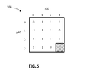
- Figure 5 illustrates the L1 higher level significance map 104 corresponding to the example significance map 102 shown in Figure 4 .
- the L1 map 104 contains a significant-coefficient-group flag for each group that contains at least one significant-coefficient flag. If any of the significant-coefficient flags within the group are non-zero, then the significant-coefficient-group flag is set to one. Otherwise, it is set to zero.
- the group containing the last-significant coefficient is at [3, 2].
- the group at [3,3] does not contain any significant-coefficient flags, so it is not included in the L1 map.
- the significant-coefficient-group flags may be converted to vector form in a scan order, in some examples .
- the scan order may be the same as the scan order specified for use with the transform unit generally.
- the significant-coefficient-group flag may use a predefined scan order than may be different from the selected scan order for the transform unit.
- the L1 map may exclude certain groups like the [0, 0] group or the last-significant-coefficient group, which will have a presumed flag value, as will be described further below.
- the L1 map need not be derived directly from the L0 map, but rather could be derived from scanning the coefficients in the transform unit in the scan order.
- the L1 map may be based on dividing the transform unit into 256 4x4 groups.
- the L1 map would be a 16x16 map containing L1 group flags.
- a further L2 map may be generated by grouping the L1 flags into a further set of 4x4 blocks (each of which would correspond to a group of 16x16 coefficients from the transform unit). Additional levels of abstraction and/or granularity may be employed in other examples.
- FIG. 6 shows, in flowchart form, an example process 200 for encoding significant-coefficient flags.
- the process 200 begins in operation 202 with the encoder determining the significant-coefficient flags and the significant-coefficient-group flags.
- the encoder scans the transform block in the scan order to determine the last-significant coefficient and the set of significant-coefficient flags.
- the significant-coefficient-group flags may be determined during the same scan (although a certain amount of buffering of values may be used in practical implementations as the scan order may involve crossing through multiple blocks; in some cases, the determination of the significant-coefficient-group flag is made when the encoder determines it has scanned the last coefficient for that group, e.g. the exit coefficient).
- the encoder may perform a second scan of either the L0 significance map or of the transform unit to determine the significant-coefficient-group flags.
- the encoder determines the context to use and then entropy encodes that significant-coefficient-group flag based on the determined context.
- the significant-coefficient-group flags may be processed in a prescribed order. In some embodiments, the prescribed order is the same as the scan order for the transform unit.
- the number of contexts and their determination may be structured in any suitable manner. An example set of contexts and method for determining contexts for significant-coefficient-group flags is described later below.
- the encoder then encodes the significant-coefficient flags.
- the encoder (working in scan order) determines the context of and encodes each significant-coefficient flag if that significant-coefficient flag falls in a group for which the significant-coefficient-group flag is set to 1. If the corresponding significant-coefficient-group flag is set to zero, then any of the significant-coefficient flags in that group are not encoded, i.e . they are skipped during the entropy encoding process.
- the encoder has produced a bitstream of encoded data which contains the encoded significant-coefficient-group flags and the encoded significant-coefficient flags that fall into a group that has at least one non-zero significant-coefficient flag.
- the bitstream does not include any significant-coefficient flags from any group that does not have at least one non-zero significant-coefficient flag.
- FIG. 7 shows, in flowchart form, an example process 300 for reconstructing significant-coefficient flags from a bitstream of encoded data.
- the bitstream may be received through a network connection, i.e . streamed, or read from a computer-readable medium, such as a memory ( e.g . flash memory, etc.) or a storage disk (e.g. DVD, BluRayTM, CD-ROM, etc.).
- the process 302 is applied in the process of reconstructing a transform unit at a decoder. Not shown is the decoding of header information, both for the sequence and for each slice or picture (depending on the syntax of the video coding standard in use).
- the position of the last-significant coefficient is decoded from the bitstream.
- This information may be represented in any applicable syntax.
- Some standards provide that the last-significant coefficient is to be specified using matrix notation, e.g. x- and y-based location within the transform unit; some standards provide that the last-significant coefficient is to be signaled using a vector of 0's with a 1 at the last-significant coefficient position, wherein the vector is mapped to the transform unit by the scan order. Any suitable syntax for specifying the last-significant coefficient may be used in operation 302.
- the significant-coefficient group flags are decoded from the bitstream.
- the significant-coefficient group flags may have been entropy encoded using whatever applicable binarization scheme is specified by the standard or specified in the header information. For example, context-adaptive binary arithmetic coding may be used in some instances.
- the significant-coefficient group flags are decoded by determining the context for each flag position (bit position in the higher level significance map - e.g. the L1 significance map), and then decoding the flag value from the bitstream and updating the context based on the flag value.
- the size of the set of significant-coefficient-group flags is known because the scan order is known and the last-significant coefficient was identified in operation 302; thus, the size of the L1 significance map is determined.
- a suitable signaling of the group sizes and positions may be provided in the syntax.
- each significant-coefficient-group flag corresponds to a respective one of the contiguous groups defined for the transform unit. One or more of the significant-coefficient flags fall into each of these groups having a significant-coefficient-group flag. Accordingly, each significant-coefficient-group flag corresponds to a respective group of the significant-coefficient flags.
- the decoder After decoding the set of significant-coefficient-group flags, then the remaining operations for reconstructing the significance map, i.e . the set of significant-coefficient flags, is performed in the prescribed scan order. The processing begins from the last-significant coefficient (but excluding that last-significant coefficient position, since it is already known to contain a non-zero coefficient). In operation 305, for each significant-coefficient flag the decoder determines whether its corresponding significant-coefficient-group flag is zero. If the corresponding significant-coefficient-group flag is non-zero, then a significant-coefficient flag is decoded from the bitstream as indicated by operation 306. That is, if the associated or corresponding significant-coefficient-group flag indicates that the group may contain at least one non-zero coefficient, then the decoder decodes a significant-coefficient flag from the bitstream for the current position.
- the decoder sets or reconstructs the current significant-coefficient flag as a zero, as indicated by operation 308. It does not decode it from the bitstream.
- the decoder determines whether it has reach the end of the scan order, i.e. the coefficient at the upper left corner of the transform unit, e.g. [0,0]. If so, then the process 300 ends; if not, then the decoder moves to the next position in the scan order in operation 312 and repeats operations 306 and 308 to reconstruct the significant-coefficient flag for that next position.
- the scan order does not result in reconstructing all significant-coefficient flags of a group before moving onto the next group. Rather, the scan order (depending on the scan order and the group geometry) scans across group boundaries such that the decoder reconstructs a few flags from one group, a few from an adjacent group, etc., working its way back to the [0,0] position in the scan order. A scanning process will be described further below that avoids this issue.
- the group containing the last-significant coefficient will always have a significant-coefficient-group flag that indicates a non-zero coefficient, so that significant-coefficient-group flag does not need to be encoded and transmitted to the decoder.
- the encoder always encodes the significant-coefficient flags for that group, and the decoder is configured to always decode the significant-coefficient flags for that group.
- Another special case that may be included in some embodiments is to always encode and decode the first group.
- This group contains the DC coefficient at [0, 0] in the transform unit. The probability of this group containing no non-zero coefficients is extremely low. Accordingly, instead of transmitting a significant-coefficient-group flag for the [0, 0] group, the encoder may be configured to always encode the significant-coefficient flags of that group and the decoder may be configured to always decode the significant-coefficient flags of that group.
- Yet another special case that may be implemented in some examples is also based on probability. It has been noted that when the group to the right and the group below a particular group both contain non-zero coefficients, then the probability that the particular group contains a non-zero coefficient is very high. Therefore, in some examples the encoder and decoder may presume that any group that has a right neighboring group and lower neighboring group that both contain non-zero coefficients, then that group has non-zero coefficient.
- the encoder does not encode a significant-coefficient-group flag for the certain group and always encoder the significant-coefficient flags for the certain group.
- the decoder recognizes that the right and lower neighbors have significant-coefficient-group flags indicating non-zero coefficients, so it will automatically assume that the certain group has non-zero coefficients and it will decode the significant-coefficient flags.
- the operation 304 includes an operation 304-1 in which the significant-coefficient-group flag for the group containing the last-significant coefficient is set to 1. The location of the last-significant coefficient is decoded from the bitstream in an earlier operation (not shown).
- the decoder then moves through the groups in the scan order. As noted in operation 304-2, the decoder moves from to the next group in the scan order from the group containing the last-significant coefficient. For this group, the decoder assesses whether the significant-coefficient-group flag for the group to the right and the significant-coefficient-group flag for the group below the current group are equal to 1. Initially, the decoder will not have flags to the right and below because it has just started, but later in the scan order (whether horizontal, vertical, or diagonal) the decoder may sometimes have reconstructed significant-coefficient-group flags in these positions relative to the current group (for groups located at the bottom edge of the transform unit, the decoder may not ever have a flag for a group below).
- the decoder sets the significant-coefficient-group flag to 1 if the special case condition is met. Otherwise, the decoder moves on to operation 304-4. In another example this special case may modified to be based on the significant-coefficient-group flags of other adjacent groups, or other groups altogether.
- the decoder decodes the significant-coefficient-group flag for the current group from the bitstream.
- the decoding includes determining the context and then decoding in accordance with the determined context.
- the decoding may be based on binary arithmetic coding (BAC), or other binarized coding/decoding processes.
- the decoder determines whether this is the next-to-last group in the scan order. If not, then the decoding is not yet finished, so the decoder cycles back to operation 304-2 to advance to the next group in the scan order. If it is the next-to-last group in the scan order, then the decoder moves on to operation 304-7 where the decoder sets the significant-coefficient-group flag for the last group, i.e. group [0,0], to 1. This is based on the special case in which that particular group is always presumed by the encoder and decoder to have at least one non-zero coefficient, so the significant-coefficient-group flag is always preset to 1 so that the significant-coefficient flags for that group are always encoded and decoded. After this operation, the decoder goes on to operation 306 or 308 ( Fig. 7 ).
- the decoding of the L1 significance map (the significant-coefficient-group flags) and the decoding of the L0 significance map (the significant-coefficient flags) as a two-stage process in which the L1 significance map is fully decoded and the L0 significance map is then decoded.
- the decoding processes may be partly intertwined. That is, the decoding of the L0 map may begin before the L1 map is fully decoded. It will be appreciated that in some embodiments the decoding of the L0 significance map may begin as soon as the first significant-coefficient-group flag has been reconstructed.
- multi-level significance map coding may be turned on and off depending on, for example, picture type. For instance, multi-level significance map coding may be enabled for I- and P-pictures, but disabled for B-pictures.
- the scan order (vertical, horizontal or diagonal) will result in crossing the boundaries of the groups when scanning the significant-coefficient flags. This might create difficulties in encoding and decoding from a hardware implementation perspective because significant buffering of data may be needed to keep track of significant-coefficient flags of partially-decoded groups in order to implement a one-pass scan. Otherwise, it may be necessary to scan twice (or more): one scan order pass for flags of the L1 map and one scan order pass for the L0 map.
- One option for implementing a one-pass scanning process and avoiding some of the memory and computational complexity issues is to use a group-based or multi-level scanning order.
- an example 16x16 transform unit 600 is illustrated.
- the example 16x16 transform unit 600 includes 16 coefficient groups, where each coefficient group is a 4x4 block of significant-coefficient flags.
- a diagonal scan order is illustrated in Figure 14 . The scan order begins with the significant-coefficient flag at [15,15] and the diagonal scan is from upper right to lower left while traversing the transform unit 600 from the lower right [15, 15] to the upper left [0, 0].
- the significance map encoding process uses a scan order starting from the last significant coefficient.
- the scanning order cuts across coefficient group boundaries. For example, consider the significant-coefficient flags at [10, 12], [11, 11], and [12, 10], as indicated by reference numerals 610, 612, and 614, respectively.
- the encoder and decoder first encounter the significant-coefficient flag 614 at position [12, 10].
- the scan order then encounters the significant-coefficient flag 612 at position [11, 11], which is the first significant-coefficient flag in that coefficient group.
- the scan order then crosses into another coefficient group when it reaches significant-coefficient flag 610 at position [10, 12].
- the decoder too may require buffering to track the previously-decoded significant-coefficient-group flags for the various groups as the decoder traverses them in scan order re-constructing the significant-coefficient flags. This results in greater memory/buffer requirements at the decoder.
- the encoding and decoding processes may employ a multi-level scanning order.
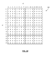
- FIG 15 shows the transform unit 600 of Figure 14 with a multi-level diagonal scan order illustrated. Within each coefficient group, a diagonal scan order is applied at the group-level, rather than across the whole transform unit 600.
- the coefficient groups themselves are processed in a scan order, which in this example implementation is also a diagonal scan order.
- diagonal is one option, and in other examples horizontal, vertical, zig-zag, or other scan orders may be applied, within the coefficient groups and/or at the group-level for ordering the processing of the coefficient groups.
- each group of significant-coefficient flags is encoded and decoded in order. That is, the encoding/decoding of the next group of significant-coefficient flags only begins once the encoding/decoding of the present group has been completed. For example, using a diagonal group scan order, the entire group of significant-coefficient flags that contains the significant-coefficient flag 614 at position [12, 10] is decoded before the decoder starts decoding the group of significant-coefficient flags that contains the significant-coefficient flag 610 at position [10, 12]. Similarly, both those groups are completely decoded before the decoder starts decoding the group containing the significant-coefficient flag 612 at position [11, 11]. This permits the encoder/decoder to more easily process the multi-level significance map in one pass since all significant-coefficient flags of a coefficient group are processed sequentially in scan order within the group.
- the multi-level or group-based scanning order further facilitates the interleaving of significant-coefficient-group flags within the bitstream.
- the encoder may write the significant-coefficient-group flag to the bitstream and may then insert the significant-coefficient flags for that coefficient group if the significant-coefficient-group flag is non-zero.
- the decoder decodes the significant-coefficient-group flag from the bitstream and, if non-zero, then decodes the significant-coefficient flags for that group in scan order within the group.
- the significant-coefficient-group flag is zero, then it sets all significant-coefficient flags for that group to zero and reads decodes the next significant-coefficient flag from the bitstream. In this manner, it reconstructs the significance map group-by-group in group scan order.
- the scan order used within the group does not necessarily need to correspond to the group scan order used for progressing from group to group.
- a diagonal scan order may be used while the processing of the groups is done in a horizontal group scan order.
- the multi-level scan order described herein matches with the coefficient grouping used for the multi-level significance map; however, in the more general case the multi-level or group-based scan order may be organized into blocks that do not necessarily correspond to the groups of significant-coefficient flags.
- the grouping or blocking for the purpose of scan order may use 8x8 blocks. In other words, in this example, the diagonal scan order would be applied to four 8x8 blocks. Note that if there is a mismatch between the grouping used for the multi-level scan order and the coefficient groups used in the multi-level significance map, then the encoder/decoder will not necessarily process each group completely before moving to the next group.
- FIG 16 shows an example method 700 for decoding a multi-level significance map using a multi-level scan order.
- the method 700 is an example process for reconstructing significant-coefficient flags from a bitstream of encoded data.
- the bitstream of encoded data includes encoded significant-coefficient-group flags.
- Each significant-coefficient-group flag corresponds to a respective group of significant-coefficient flags.
- Each non-zero significant-coefficient-group flag in the bitstream is followed by the significant-coefficient flags of its respective group in a scan order.
- the method 700 begins with decoding of the last-significant coefficient position from the bitstream in operation 702.
- the last-significant coefficient position may be signaled in any one of a number of ways.
- the decoder decodes the significant-coefficient flags from the bitstream for the significant-coefficients within the coefficient group containing the last-significant coefficient.
- the decoding in operation 704 is performed in a scan order (which may be diagonal, vertical, horizontal, etc.) within the coefficient group, starting with the significant-coefficient position after the position of the last-significant position and working back towards the upper left coefficient in the scan order.
- the current coefficient group (indexed as CG) is set to be the group after the group containing the last-significant coefficient.
- the group scan order is the order in which the coefficient groups are decoded, starting with the group after the group containing the last-significant coefficient and working back towards the upper left group in the transform unit (the group containing the DC coefficient at position [0,0]) in the group scan order.
- the group scan order may be vertical, horizontal, diagonal, etc.
- the decoder reconstructs the significant-coefficient-group flag for the current coefficient group (indexed as CG).
- This reconstruction includes decoding the significant-coefficient-group flag from the bitstream, unless a special case applies.
- a special case is when the significant-coefficient-group flags for the group to the right and the group below the current coefficient group are both non-zero. In this situation, the significant-coefficient-group flag may be presumed to be non-zero by default.
- the significant-coefficient flags of the corresponding coefficient group are all set to zero. If the reconstructed significant-coefficient group flag is non-zero, then in operation 714 the significant-coefficient flags of the corresponding coefficient group are decoded from the bitstream in scan order within that group.
- the BAC engine uses contexts.
- the present application proposes using four new contexts for encoding the significant-coefficient-group flags. Two contexts are for luma encoding/decoding and two are for chroma encoding/decoding.
- the context model can be changed to use the significant-coefficient-group flag for the adjacent group to the left of the current group and the significant-coefficient-group flag for the adjacent group above the current group to determine the context.
- the context determination process may also include special cases.
- the upper left group may always be assigned context 1.
- L[i] denote the significance flag of coefficient group i at level L and let N denote the number of the coefficient groups at level L.
- c(*) of i and all available L[j] we use a function c(*) of i and all available L[j] to determine a context C_i for L[i].
- the weighting coefficients bj may not necessarily be constants.
- the transform unit is presumed to have been divided into sixteen contiguous blocks to form the coefficient groups. For example, a 16x16 TU is divided into 4x4 blocks and a 32x32 TU is divided into 8x8 blocks. In another example, the transform units may be divided into 4x4 blocks or other sized blocks.
- variable ctxIdxInc depends on the current position (xCG, yCG), and previously decoded bins of the syntax element significant_coeffgroup_flag. For the derivation of ctxIdxInc, the following applies.
- ctxIdxInc is set equal to a default context value.
- ctxIdxInc 44 + significant_subblock_flag[xCG+ 1][yCG]
- ctxIdxInc 44 + significant_subblock_flag[xCG][yCG + 1]
- ctxIdxInc 44 + max ⁇ significant_subblock_flag[xCG + 1][yCG], significant_subblock_flag[xCG][yCG +1] ⁇
- the value 44 in the above expressions is one example of a default index value. Other values may be used in other embodiments, including 0.
- RDOQ rate-distortion optimized quantization
- soft-quantization is a process of determining optimal quantized transform domain coefficients based on a rate-distortion optimization expression. Accordingly, the quantized transform domain coefficients that result from RDOQ may or may not be the same as the quantized transform domain coefficients that were arrived at through the normal transform and quantization process. In some cases, the coefficient values may have been modified by the RDOQ process because the resulting distortion was determined to have been less costly than the consequent savings in transmission cost.
- the RDOQ process normally evaluates four costs in determining the rate component.
- the four rate costs include the last position rate, the significance rate (L0 rate), the coefficient rate, and the coded block parameter (CBP) rate.
- L0 rate significance rate
- CBP coded block parameter
- the RDOQ process may be modified to perform a two-stage RDOQ with regard to significance maps. First, the RDOQ process is applied to determine the best last position and coefficient values and, thus, the L1 significant-coefficient flags. In a second stage, with the last position fixed, the RDOQ process may then be applied again with regard to the L1 rate to determine whether there is a rate-distortion (RD) cost justification for zeroing any coefficients.
- RD rate-distortion
- FIG 9 shows, in flowchart form, an example RDOQ process 400 for encoding of multi-level significance maps.
- the process 400 uses RDOQ to obtain the optimal quantized transform coefficients and to determine the position of the last significant coefficient, i.e. a L0 RDOQ.
- the process 400 then fixes the last position and adjusts the current RD cost to account for the effect of the additional levels of significance maps. Then, it uses a greedy approach to further optimize the transform coefficients.
- Operation 402 reflects the use of RDOQ to obtain optimal quantized transform domain coefficients, which provides a last-significant coefficient position. Operation 402 results in a certain RD cost based on the rates for transmitting the last position, significance map corresponding to the optimal coefficients, the coefficient values, and CBP.
- the last significant position is fixed. That is the last group will contain a non-zero coefficient, i.e . the last significant-coefficient-group flag is fixed at 1.
- the encoder then greedily determines whether costs savings are found by zeroing coefficients in other groups.
- the process 400 may be performed in the scan order in some examples although it could be processed in another order.
- the encoder assesses whether it is done with the L1 RDOQ, e.g. whether it has reached the group just before the [0, 0] group (the [0, 0] group does not get zeroed if the encoder and decoder are configured to presume there is at least one non-zero coefficient in that group, as described in the special cases outlined above). If there are further groups to assess, then the process 400 continues at operation 414, where the encoder moves to the next group (using scan order in some examples
- the L1 RDOQ process may result, for example, in an optimized L0 significance map 500 shown in Figure 10 , and the associated or corresponding L1 significance map 502 shown in Figure 11 .
- the RDOQ process can be extended to determine the optimal coefficient group size for the current TU.
- the process 400 is repeated for multiple rounds, with each round assuming a different coefficient group size and with operation 410 modified so that transform coefficients are not actually set to 0.
- this modified RDOQ process calculates the RD cost for a particular coefficient group size.
- the RDOQ selects the coefficient group size that yields the least RD cost and finally, sets any transform coefficients to 0 as required.
- the encoder encodes the value of the optimal coefficient group size into the bitstream so that it can be obtained and used by the decoder.
- the coefficient group sizes that are tested may be based upon the transform unit size. For example, a 32x32 transform unit may test group sizes 8x8, 4x4 and 2x2. The groups to be tested may be selectable, and the encoder may indicate (for example in the sequence header) what group sizes will be tests for each transform unit size.
- the encoder and decoder have agreed that for 16x16 TUs, the modified RDOQ will test two different coefficient group sizes: 2x2 and 4x4, denoted by 1 and 0, respectively. If the modified RDOQ determines that 2x2 is optimal, the encoder encodes a bin 1 into the bitstream before the significant-coefficient-group flags. The decoder decodes this bin before the significant-coefficient-group flags and knows that the coefficient group size for the current TU is 2x2.
- the RDOQ process takes advantage of the multi-level scan: L1/L0 RDOQ is performed in a group by group manner followed by determining the last position.
- L1/L0 RDOQ is performed in a group by group manner followed by determining the last position.
- Step 2 Do L0 RDOQ for each coefficient in the coefficient group at group position nCG following the scan order within the group as specified by multi-level scan.
- Step 3 If the resulting coefficient group after Step 2 has non-zero coefficients, nCG is greater than 0, and either the right neighbor or the below neighbor has its significant coefficient group flag set to zero, do L1 RDOQ for the coefficient group: 1) calculate the RD cost setting the L1 flag to zero for the present coefficient group; 2) if the cost is smaller than the RD cost resulting from Step 2, set all coefficients in the coefficient group to zero, and the significant coefficient group flag of the present group to 0.
- Step 4 Decrease nCG by 1.
- Step 5 Repeate Steps 1-4 until nCG is equal to 0.
- Step 6 Determine the last position minimizing the RD cost.
- FIG 17 illustrates this example in flowchart form showing example process 450 for RDOQ encoding of a multi-level significance map with a multi-level scan order.
- the process 450 includes a first operation 452 of setting the number of coefficient groups nCG based on the group containing the last significant coefficient.
- a L0 RDOQ process is performed on the coefficients within the current coefficient group; that is, rate-distortion optimization is used to determined optimal coefficient values for each coefficient in the current group.
- operation 456 if there are no non-zero coefficients, then the process 450 skips to operation 464 to move to the next coefficient group in the scan order and cycle back to operation 454 to perform L0 RDOQ on that next coefficient group. Note that the process 450 also skips to operation 464 if the lower and right neighbor groups have significant-coefficient-flags that are both non-zero.
- the process 450 moves to operation 458 in which L1 RDOQ is performed with respect to the current group. That is the RD cost is calculated if the L1 flag (significant-coefficient-group flag) were set to zero, thereby resulting in all zero coefficients at the decoder. If the rate savings versus the distortion result in a lower RD cost, as evaluated in operation 460, then in operation 462 the coefficients are zeroed and the significant-coefficient-group flag is set to zero.
- the significant-coefficient-group flags may be denoted and defined as:
- This flag specifies, for the coefficient group position (xCG, yCG) within the current 16x16 or 32x32 transform block, whether the corresponding coefficient group at location (xCG, yCG) has non-zero coefficients as follows:
- the significant_coeffgroup_flag[ xCG][yCG] does not apply to 4x4 and 8x8 transform blocks.
- the following pseudo-code illustrates one example implementation of multi-level significance maps within the decoding process for reconstruction quantized transform domain coefficients (residuals).
- the first portion of the pseudo-code includes decoding the last-significant coefficient position.
- the number of coefficient groups are then determined, if the transform unit is 16x16 or larger (as indicated by if (log2TrafoSize > 3)), and the number of coefficients in each coefficient group.
- the second if-else statement reflects the decoding of the significant-coefficient flags within the coefficient group containing the last-significant coefficient.
- the second for-loop within the main if-else statement reflects the group-by-group processing in group scan order.
- a further if-else statement provides that if the significant-coefficient-group flag is non-zero, then the significant-coefficient flags for that group are decoded from the bitstream in scan order. All but the last (upper left) significant-coefficient flag in the group is decoded from the bitstream. The decoder then assesses whether any of the decoded significant-coefficient flags for that group are nonzero. If so, then it decodes the last (upper left) significant-coefficient flag for that group; and otherwise, it sets it to 1 because it knows that it cannot be zero.
- the foregoing pseudo-code shows one example implementation of the example method 700 described above in connection with Figure 16 .
- the significant-coefficient-group flags and their corresponding significant-coefficient flags are interleaved in this embodiment.
- a distinction between the example method 700 in Figure 16 and the example pseudocode is that the example method 700 deals with the special case of the upper left group in operation 720, whereas the psuedocode deals with that special case within operation 708 by setting the significant-coefficient-group flag for that group to be non-zero and thus decoding that group's significant-coefficient flags from the bitstream in operation 714.
- the coefficient group size may be fixed.
- (yC ! last_significant_coeff_y)) ⁇ num
- the significant-coefficient-group flags may not be interleaved with the significant-coefficient flags within the bitstream. That is, the significant-coefficient-group flags are encoded in the bitstream together and the significant-coefficient flags, group-by-group in the scan order, follow them in the bitstream.
- (yC ! last_significant_coeff_y)) ⁇ num
- the encoder 900 includes a processor 902, memory 904, and an encoding application 906.
- the encoding application 906 may include a computer program or application stored in memory 904 and containing instructions for configuring the processor 902 to perform operations such as those described herein.
- the encoding application 906 may encode and output bitstreams encoded in accordance with the multi-level significance map processes described herein. It will be understood that the encoding application 906 may be stored in on a computer readable medium, such as a compact disc, flash memory device, random access memory, hard drive, etc.
- the decoder 1000 includes a processor 1002, a memory 1004, and a decoding application 1006.
- the decoding application 1006 may include a computer program or application stored in memory 1004 and containing instructions for configuring the processor 1002 to perform operations such as those described herein.
- the decoding application 1006 may include an entropy decoder configured to reconstruct residuals based on multi-level significance maps, as described herein. It will be understood that the decoding application 1006 may be stored in on a computer readable medium, such as a compact disc, flash memory device, random access memory, hard drive, etc.
- the decoder and/or encoder may be implemented in a number of computing devices, including, without limitation, servers, suitably programmed general purpose computers, audio/video encoding and playback devices, set-top television boxes, television broadcast equipment, and mobile devices.
- the decoder or encoder may be implemented by way of software containing instructions for configuring a processor to carry out the functions described herein.
- the software instructions may be stored on any suitable non-transitory computer-readable memory, including CDs, RAM, ROM, Flash memory, etc.
- the encoder described herein and the module, routine, process, thread, or other software component implementing the described method/process for configuring the encoder may be realized using standard computer programming techniques and languages.
- the present application is not limited to particular processors, computer languages, computer programming conventions, data structures, other such implementation details.
- Those skilled in the art will recognize that the described processes may be implemented as a part of computer-executable code stored in volatile or non-volatile memory, as part of an application-specific integrated chip (ASIC), etc.
- ASIC application-specific integrated chip
Claims (14)
- Procédé de reconstitution de drapeaux de coefficients significatifs pour une unité de transformation, à partir d'un flux binaire de données codées, le flux binaire comprenant des drapeaux de groupes de coefficients significatifs codés, dans lequel chaque drapeau de groupe de coefficients significatifs correspond à un groupe respectif de drapeaux de coefficients significatifs, le procédé comprenant les étapes consistant à :pour chacun des groupes respectifs de drapeaux de coefficients significatifs, dans un ordre inversé de balayage du groupe, l'ordre inversé de balayage du groupe partant du groupe contenant le drapeau de coefficient significatif pour un dernier coefficient significatif indiquant la position du dernier coefficient significatif non nul dans l'unité de transformation et reculant dans les groupes dans l'ordre inverse jusqu'à atteindre le groupe contenant la position DC dans l'unité de transformation :renseigner à 1 le drapeau de groupe de coefficients significatifs du groupe si ce groupe soit contient le drapeau de coefficient significatif pour le dernier coefficient significatif, soit contient le drapeau de coefficient significatif pour un coefficient à la position DC dans l'unité de transformation ; etsinon, décoder le drapeau de groupe de coefficients significatifs pour ce groupe à partir du flux binaire de données codées ; et- si le drapeau du groupe de coefficients significatifs est à 1, reconstituer les drapeaux de coefficients significatifs dans un ordre inverse de balayage au sein de ce groupe :en inférant, sans décodage à partir du flux binaire, que le drapeau de coefficient significatif à la position (0, 0) de ce groupe est à 1 si le drapeau de groupe de coefficients significatifs qui est décodé est non nul et si tous les drapeaux de groupes de coefficients significatifs antérieurs dans ce groupe sont nuls ; et sinonen décodant le drapeau de coefficient significatif à partir du flux binaire ; et- si le drapeau de groupe de coefficients significatifs est nul, en renseignant à zéro tous les drapeaux de coefficients significatifs dans le groupe.
- Procédé selon la revendication 1, dans lequel l'ordre inverse de balayage du groupe est un ordre prescrit dans lequel les groupes respectifs de drapeaux de coefficients significatifs doivent être reconstitués.
- Procédé selon la revendication 2, dans lequel chaque drapeau de groupe de coefficients significatifs non nul dans le flux binaire est suivi de ses drapeaux de coefficients significatifs dans l'ordre inverse de balayage au sein de ce groupe.
- Procédé selon la revendication 2 ou la revendication 3, dans lequel l'ordre prescrit pour la reconstitution des groupes respectifs est un ordre soit horizontal, soit vertical, soit diagonal.
- Procédé selon l'une quelconque des revendications 1 à 4, dans lequel l'ordre inverse de balayage est un ordre prescrit dans lequel doivent être reconstitués les drapeaux de coefficients significatifs dans chacun des groupes.
- Procédé selon la revendication 5, dans lequel l'ordre prescrit des drapeaux de coefficients significatifs au sein de chaque groupe est un ordre soit horizontal, soit vertical, soit diagonal.
- Procédé selon l'une quelconque des revendications 1 à 6, dans lequel les groupes sont des blocs carrés contigus.
- Procédé selon l'une quelconque des revendications 1 à 6, dans lequel chaque groupe est un bloc rectangulaire non carré.
- Procédé selon l'une quelconque des revendications 1 à 8, dans lequel l'étape de reconstitution de l'un des drapeaux de groupes de coefficients significatifs comprend l'étape consistant à déterminer un contexte pour le drapeau de groupe de coefficients significatifs en fonction des drapeaux de groupes de coefficients significatifs reconstitués pour deux groupes voisins, dans lequel les deux groupes voisins comprennent un voisin droit et un voisin inférieur et dans lequel le contexte est de 0 si les deux drapeaux de groupes de coefficients significatifs pour les deux groupes voisins sont de 0 et le contexte est sinon de 1.
- Décodeur destiné à décoder un flux binaire de données codées afin de reconstituer des drapeaux de coefficients significatifs pour une unité de transformation, le décodeur comprenant :un processeur ;une mémoire ; etune application de décodage enregistrée dans la mémoire et contenant des instructions destinées à configurer le processeur pour exécuter le procédé selon l'une quelconque des revendications 1 à 9.
- Support non volatil lisible par un processeur qui porte des instructions exécutables par un processeur qui, lorsqu'elles sont exécutées, configurent un ou plusieurs processeurs pour exécuter le procédé selon l'une quelconque des revendications 1 à 9.
- Procédé de codage de drapeaux de coefficients significatifs pour une unité de transformation, chacun des drapeaux de coefficients significatifs appartenant à un groupe respectif de drapeaux de coefficients significatifs et chaque groupe respectif possédant un drapeau de groupe de coefficients significatifs correspondant, le procédé comprenant les étapes consistant à :pour chacun des groupes respectifs de drapeaux de coefficients significatifs, dans un ordre inversé de balayage du groupe, l'ordre inversé de balayage du groupe partant du groupe contenant le drapeau de coefficient significatif pour un dernier coefficient significatif indiquant la position du dernier coefficient significatif non nul dans l'unité de transformation et reculant dans les groupes dans l'ordre inverse jusqu'à atteindre le groupe contenant la position DC dans l'unité de transformation :coder le drapeau de coefficient significatif de ce groupe à moins que le groupe ne contienne le dernier coefficient significatif ou que ce groupe contienne la position DC, dans lequel le drapeau de groupe de coefficients significatifs correspondant à ce groupe est mis à 1 si ce groupe contient au moins un drapeau de coefficient significatif non nul et mis à 0 sinon ; etsi le drapeau de groupe de coefficients significatifs de ce groupe est à 1 ou si ce groupe contient le dernier coefficient significatif ou si ce groupe contient la position DC, coder les drapeaux de coefficients significatifs dans ce groupe dans un ordre inverse de balayage, sauf le drapeau de coefficient significatif à la position (0, 0) dans ce groupe lorsque les deux conditions suivantes sont satisfaites :tous les drapeaux de coefficients significatifs précédents dans ce groupe sont nuls ; etle drapeau de coefficient significatif ne correspond pas à la position DC.
- Codeur destiné à coder des drapeaux de coefficients significatifs pour une unité de transformation, le codeur comprenant :un processeur ;une mémoire ; etune application de codage enregistrée en mémoire et contenant des instructions destinées à configurer le processeur afin d'exécuter le procédé selon la revendication 12.
- Support non volatil lisible par un processeur qui porte des instructions exécutables par un processeur qui, lorsqu'elles sont exécutées, configurent un ou plusieurs processeurs pour exécuter le procédé selon la revendication 12.
Applications Claiming Priority (1)
| Application Number | Priority Date | Filing Date | Title |
|---|---|---|---|
| US201161561872P | 2011-11-19 | 2011-11-19 |
Publications (2)
| Publication Number | Publication Date |
|---|---|
| EP2595380A1 EP2595380A1 (fr) | 2013-05-22 |
| EP2595380B1 true EP2595380B1 (fr) | 2015-10-21 |
Family
ID=46245802
Family Applications (1)
| Application Number | Title | Priority Date | Filing Date |
|---|---|---|---|
| EP12164134.4A Active EP2595380B1 (fr) | 2011-11-19 | 2012-04-13 | Balayage de cartes de signification multiniveau |
Country Status (11)
| Country | Link |
|---|---|
| US (3) | US9743098B2 (fr) |
| EP (1) | EP2595380B1 (fr) |
| JP (2) | JP5542188B2 (fr) |
| KR (1) | KR101538832B1 (fr) |
| CN (1) | CN103124349B (fr) |
| AU (1) | AU2012245178B2 (fr) |
| BR (1) | BR102012029413B1 (fr) |
| CA (1) | CA2773990C (fr) |
| HK (1) | HK1179451A1 (fr) |
| SG (1) | SG190516A1 (fr) |
| TW (1) | TWI483618B (fr) |
Families Citing this family (26)
| Publication number | Priority date | Publication date | Assignee | Title |
|---|---|---|---|---|
| US8964849B2 (en) * | 2011-11-01 | 2015-02-24 | Blackberry Limited | Multi-level significance maps for encoding and decoding |
| WO2013102380A1 (fr) * | 2012-01-03 | 2013-07-11 | Mediatek Inc. | Procédé et appareil pour carte d'importance basée sur un bloc et sélection de contexte par indicateur de groupe d'importance |
| US20130182772A1 (en) * | 2012-01-13 | 2013-07-18 | Qualcomm Incorporated | Determining contexts for coding transform coefficient data in video coding |
| AU2012200319B2 (en) * | 2012-01-19 | 2015-11-26 | Canon Kabushiki Kaisha | Method, apparatus and system for encoding and decoding the significance map for residual coefficients of a transform unit |
| US9106918B2 (en) * | 2012-01-20 | 2015-08-11 | Sony Corporation | Coefficient coding harmonization in HEVC |
| US9350998B2 (en) | 2012-06-29 | 2016-05-24 | Qualcomm Incorporated | Coding of significance flags |
| US9386306B2 (en) | 2012-08-15 | 2016-07-05 | Qualcomm Incorporated | Enhancement layer scan order derivation for scalable video coding |
| CN104604225B (zh) | 2012-09-10 | 2018-01-26 | 太阳专利托管公司 | 图像编码方法、图像解码方法、图像编码装置、图像解码装置及图像编码解码装置 |
| US9538175B2 (en) * | 2012-09-26 | 2017-01-03 | Qualcomm Incorporated | Context derivation for context-adaptive, multi-level significance coding |
| KR101502144B1 (ko) * | 2013-08-22 | 2015-03-12 | 주식회사 에스원 | 계수 정보를 변환하는 방법 및 장치 |
| US9445132B2 (en) * | 2013-09-09 | 2016-09-13 | Qualcomm Incorporated | Two level last significant coefficient (LSC) position coding |
| KR102218196B1 (ko) * | 2013-10-28 | 2021-02-23 | 삼성전자주식회사 | 인코더, 이의 동작 방법과, 상기 인코더를 포함하는 장치들 |
| US9781424B2 (en) | 2015-01-19 | 2017-10-03 | Google Inc. | Efficient context handling in arithmetic coding |
| JP6476900B2 (ja) * | 2015-01-21 | 2019-03-06 | 富士通株式会社 | 動画像符号化装置、動画像符号化方法及び動画像符号化用コンピュータプログラム |
| US11233998B2 (en) | 2015-05-29 | 2022-01-25 | Qualcomm Incorporated | Coding data using an enhanced context-adaptive binary arithmetic coding (CABAC) design |
| CN115499663A (zh) * | 2015-06-08 | 2022-12-20 | 上海天荷电子信息有限公司 | 单编码模式参考不同程度重构像素的图像压缩方法和装置 |
| US10631013B2 (en) | 2015-06-11 | 2020-04-21 | Lg Electronics Inc. | Method for re-positioning significant coefficient in image encoding/decoding process and device therefor |
| WO2017057953A1 (fr) * | 2015-09-30 | 2017-04-06 | 엘지전자 주식회사 | Procédé et dispositif de codage de signal résiduel dans un système de codage vidéo |
| EP3264763A1 (fr) * | 2016-06-29 | 2018-01-03 | Thomson Licensing | Procédé et appareil de codage de drapeau d'importance amélioré à l'aide de prédicteur local simple |
| US11863798B2 (en) * | 2016-07-13 | 2024-01-02 | Electronics And Telecommunications Research Institute | Image encoding/decoding method and device |
| KR102302797B1 (ko) | 2017-04-13 | 2021-09-16 | 엘지전자 주식회사 | 영상의 부호화/복호화 방법 및 이를 위한 장치 |
| US10523968B2 (en) | 2017-09-18 | 2019-12-31 | Google Llc | Coding of last significant coefficient flags |
| CN110650343A (zh) | 2018-06-27 | 2020-01-03 | 中兴通讯股份有限公司 | 图像的编码、解码方法及装置、电子设备及系统 |
| AU2018233042A1 (en) | 2018-09-21 | 2020-04-09 | Canon Kabushiki Kaisha | Method, apparatus and system for encoding and decoding a tree of blocks of video samples |
| AU2019201649A1 (en) | 2019-03-11 | 2020-10-01 | Canon Kabushiki Kaisha | Method, apparatus and system for encoding and decoding a tree of blocks of video samples |
| CN115623218A (zh) * | 2021-07-13 | 2023-01-17 | 财团法人工业技术研究院 | 特征数据编码方法、编码器、特征数据解码方法及解码器 |
Citations (1)
| Publication number | Priority date | Publication date | Assignee | Title |
|---|---|---|---|---|
| US20110096834A1 (en) * | 2009-10-28 | 2011-04-28 | Samsung Electronics Co., Ltd. | Method and apparatus for encoding residual block, and method and apparatus for decoding residual block |
Family Cites Families (14)
| Publication number | Priority date | Publication date | Assignee | Title |
|---|---|---|---|---|
| US7190840B2 (en) * | 2002-01-07 | 2007-03-13 | Hewlett-Packard Development Company, L.P. | Transform coefficient compression using multiple scans |
| KR100667808B1 (ko) * | 2005-08-20 | 2007-01-11 | 삼성전자주식회사 | 영상의 인트라 예측 부호화, 복호화 방법 및 장치 |
| US20070071331A1 (en) | 2005-09-24 | 2007-03-29 | Xiteng Liu | Image compression by economical quaternary reaching method |
| KR100873636B1 (ko) * | 2005-11-14 | 2008-12-12 | 삼성전자주식회사 | 단일 부호화 모드를 이용하는 영상 부호화/복호화 방법 및장치 |
| KR101356733B1 (ko) * | 2007-03-07 | 2014-02-05 | 삼성전자주식회사 | 컨텍스트 기반 적응적 이진 산술 부호화, 복호화 방법 및장치 |
| KR101375668B1 (ko) * | 2008-03-17 | 2014-03-18 | 삼성전자주식회사 | 변환 계수의 부호화, 복호화 방법 및 장치 |
| EP2154894A1 (fr) | 2008-08-15 | 2010-02-17 | Thomson Licensing | Codage vidéo avec codage des locations des coefficients significatifs dans un bloc de coefficients |
| TWI482499B (zh) * | 2008-10-03 | 2015-04-21 | Ind Tech Res Inst | 影像訊號處理裝置和方法 |
| US8879632B2 (en) | 2010-02-18 | 2014-11-04 | Qualcomm Incorporated | Fixed point implementation for geometric motion partitioning |
| US8942282B2 (en) * | 2010-04-12 | 2015-01-27 | Qualcomm Incorporated | Variable length coding of coded block pattern (CBP) in video compression |
| PL2559166T3 (pl) * | 2010-04-13 | 2018-04-30 | Fraunhofer-Gesellschaft zur Förderung der angewandten Forschung e.V. | Koder i dekoder dzielący interwał prawdopodobieństwa |
| PT3244612T (pt) | 2010-04-13 | 2018-11-14 | Ge Video Compression Llc | Codificação de mapas de significância e blocos de coeficientes de transformada |
| US9154801B2 (en) * | 2010-09-30 | 2015-10-06 | Texas Instruments Incorporated | Method and apparatus for diagonal scan and simplified coding of transform coefficients |
| US8767824B2 (en) * | 2011-07-11 | 2014-07-01 | Sharp Kabushiki Kaisha | Video decoder parallelization for tiles |
-
2012
- 2012-04-13 CA CA2773990A patent/CA2773990C/fr active Active
- 2012-04-13 US US13/446,186 patent/US9743098B2/en active Active
- 2012-04-13 EP EP12164134.4A patent/EP2595380B1/fr active Active
- 2012-10-31 SG SG2012080610A patent/SG190516A1/en unknown
- 2012-11-06 AU AU2012245178A patent/AU2012245178B2/en active Active
- 2012-11-12 JP JP2012248205A patent/JP5542188B2/ja active Active
- 2012-11-16 CN CN201210464858.4A patent/CN103124349B/zh not_active Expired - Fee Related
- 2012-11-19 TW TW101143140A patent/TWI483618B/zh active
- 2012-11-19 KR KR1020120131064A patent/KR101538832B1/ko active IP Right Grant
- 2012-11-19 BR BR102012029413-3A patent/BR102012029413B1/pt active IP Right Grant
-
2013
- 2013-05-31 HK HK13106432.8A patent/HK1179451A1/xx unknown
-
2014
- 2014-05-07 JP JP2014095988A patent/JP5925830B2/ja active Active
-
2017
- 2017-07-24 US US15/657,719 patent/US10116950B2/en active Active
-
2018
- 2018-10-10 US US16/156,058 patent/US10681362B2/en active Active
Patent Citations (1)
| Publication number | Priority date | Publication date | Assignee | Title |
|---|---|---|---|---|
| US20110096834A1 (en) * | 2009-10-28 | 2011-04-28 | Samsung Electronics Co., Ltd. | Method and apparatus for encoding residual block, and method and apparatus for decoding residual block |
Also Published As
| Publication number | Publication date |
|---|---|
| CA2773990A1 (fr) | 2013-05-19 |
| KR20130056183A (ko) | 2013-05-29 |
| CN103124349A (zh) | 2013-05-29 |
| US9743098B2 (en) | 2017-08-22 |
| EP2595380A1 (fr) | 2013-05-22 |
| HK1179451A1 (en) | 2013-09-27 |
| US20190052890A1 (en) | 2019-02-14 |
| JP5925830B2 (ja) | 2016-05-25 |
| JP2013110740A (ja) | 2013-06-06 |
| BR102012029413A8 (pt) | 2021-08-24 |
| AU2012245178B2 (en) | 2013-11-28 |
| AU2012245178A1 (en) | 2013-06-06 |
| TW201334550A (zh) | 2013-08-16 |
| KR101538832B1 (ko) | 2015-07-22 |
| US10116950B2 (en) | 2018-10-30 |
| CA2773990C (fr) | 2015-06-30 |
| BR102012029413B1 (pt) | 2022-02-15 |
| CN103124349B (zh) | 2016-09-14 |
| US20180007376A1 (en) | 2018-01-04 |
| SG190516A1 (en) | 2013-06-28 |
| JP5542188B2 (ja) | 2014-07-09 |
| US10681362B2 (en) | 2020-06-09 |
| BR102012029413A2 (pt) | 2016-02-16 |
| JP2014195269A (ja) | 2014-10-09 |
| US20130128985A1 (en) | 2013-05-23 |
| TWI483618B (zh) | 2015-05-01 |
Similar Documents
| Publication | Publication Date | Title |
|---|---|---|
| US10681362B2 (en) | Multi-level significance map scanning | |
| US10911758B2 (en) | Multi-level significance maps for encoding and decoding | |
| EP2590409B1 (fr) | Cartes de signification multi-niveaux pour le codage et le décodage | |
| EP2688300A1 (fr) | Sélection de contexte basée sur la position pour un codage et décodage d'étiquette supérieur à un | |
| CA2802285C (fr) | Methodes et dispositifs de selection d'un ensemble de contextes | |
| EP2618573A1 (fr) | Procédés et dispositifs pour modelage de contexte pour activer un traitement modulaire | |
| CA2800119C (fr) | Procedes et systemes pour pipeline dans un codage et un decodage arithmetiques binaires |
Legal Events
| Date | Code | Title | Description |
|---|---|---|---|
| PUAI | Public reference made under article 153(3) epc to a published international application that has entered the european phase |
Free format text: ORIGINAL CODE: 0009012 |
|
| 17P | Request for examination filed |
Effective date: 20120413 |
|
| AK | Designated contracting states |
Kind code of ref document: A1 Designated state(s): AL AT BE BG CH CY CZ DE DK EE ES FI FR GB GR HR HU IE IS IT LI LT LU LV MC MK MT NL NO PL PT RO RS SE SI SK SM TR |
|
| AX | Request for extension of the european patent |
Extension state: BA ME |
|
| RAP1 | Party data changed (applicant data changed or rights of an application transferred) |
Owner name: BLACKBERRY LIMITED |
|
| REG | Reference to a national code |
Ref country code: HK Ref legal event code: DE Ref document number: 1179451 Country of ref document: HK |
|
| RAP1 | Party data changed (applicant data changed or rights of an application transferred) |
Owner name: BLACKBERRY LIMITED |
|
| 17Q | First examination report despatched |
Effective date: 20140319 |
|
| REG | Reference to a national code |
Ref country code: DE Ref legal event code: R079 Ref document number: 602012011719 Country of ref document: DE Free format text: PREVIOUS MAIN CLASS: H04N0007260000 Ipc: H04N0019700000 |
|
| GRAP | Despatch of communication of intention to grant a patent |
Free format text: ORIGINAL CODE: EPIDOSNIGR1 |
|
| RIC1 | Information provided on ipc code assigned before grant |
Ipc: H04N 19/13 20140101ALI20150729BHEP Ipc: H04N 19/18 20140101ALI20150729BHEP Ipc: H04N 19/136 20140101ALI20150729BHEP Ipc: H04N 19/70 20140101AFI20150729BHEP Ipc: H04N 19/46 20140101ALI20150729BHEP Ipc: H04N 19/63 20140101ALI20150729BHEP Ipc: H04N 19/40 20140101ALI20150729BHEP Ipc: H04N 19/129 20140101ALI20150729BHEP Ipc: H04N 19/61 20140101ALI20150729BHEP |
|
| GRAS | Grant fee paid |
Free format text: ORIGINAL CODE: EPIDOSNIGR3 |
|
| INTG | Intention to grant announced |
Effective date: 20150817 |
|
| GRAA | (expected) grant |
Free format text: ORIGINAL CODE: 0009210 |
|
| AK | Designated contracting states |
Kind code of ref document: B1 Designated state(s): AL AT BE BG CH CY CZ DE DK EE ES FI FR GB GR HR HU IE IS IT LI LT LU LV MC MK MT NL NO PL PT RO RS SE SI SK SM TR |
|
| REG | Reference to a national code |
Ref country code: GB Ref legal event code: FG4D |
|
| REG | Reference to a national code |
Ref country code: CH Ref legal event code: EP |
|
| REG | Reference to a national code |
Ref country code: AT Ref legal event code: REF Ref document number: 757299 Country of ref document: AT Kind code of ref document: T Effective date: 20151115 |
|
| REG | Reference to a national code |
Ref country code: IE Ref legal event code: FG4D |
|
| REG | Reference to a national code |
Ref country code: DE Ref legal event code: R096 Ref document number: 602012011719 Country of ref document: DE |
|
| REG | Reference to a national code |
Ref country code: NL Ref legal event code: FP |
|
| REG | Reference to a national code |
Ref country code: LT Ref legal event code: MG4D |
|
| REG | Reference to a national code |
Ref country code: AT Ref legal event code: MK05 Ref document number: 757299 Country of ref document: AT Kind code of ref document: T Effective date: 20151021 |
|
| REG | Reference to a national code |
Ref country code: HK Ref legal event code: GR Ref document number: 1179451 Country of ref document: HK |
|
| REG | Reference to a national code |
Ref country code: FR Ref legal event code: PLFP Year of fee payment: 5 |
|
| PG25 | Lapsed in a contracting state [announced via postgrant information from national office to epo] |
Ref country code: IS Free format text: LAPSE BECAUSE OF FAILURE TO SUBMIT A TRANSLATION OF THE DESCRIPTION OR TO PAY THE FEE WITHIN THE PRESCRIBED TIME-LIMIT Effective date: 20160221 Ref country code: HR Free format text: LAPSE BECAUSE OF FAILURE TO SUBMIT A TRANSLATION OF THE DESCRIPTION OR TO PAY THE FEE WITHIN THE PRESCRIBED TIME-LIMIT Effective date: 20151021 Ref country code: NO Free format text: LAPSE BECAUSE OF FAILURE TO SUBMIT A TRANSLATION OF THE DESCRIPTION OR TO PAY THE FEE WITHIN THE PRESCRIBED TIME-LIMIT Effective date: 20160121 Ref country code: IT Free format text: LAPSE BECAUSE OF FAILURE TO SUBMIT A TRANSLATION OF THE DESCRIPTION OR TO PAY THE FEE WITHIN THE PRESCRIBED TIME-LIMIT Effective date: 20151021 Ref country code: LT Free format text: LAPSE BECAUSE OF FAILURE TO SUBMIT A TRANSLATION OF THE DESCRIPTION OR TO PAY THE FEE WITHIN THE PRESCRIBED TIME-LIMIT Effective date: 20151021 Ref country code: ES Free format text: LAPSE BECAUSE OF FAILURE TO SUBMIT A TRANSLATION OF THE DESCRIPTION OR TO PAY THE FEE WITHIN THE PRESCRIBED TIME-LIMIT Effective date: 20151021 |
|
| PG25 | Lapsed in a contracting state [announced via postgrant information from national office to epo] |
Ref country code: AT Free format text: LAPSE BECAUSE OF FAILURE TO SUBMIT A TRANSLATION OF THE DESCRIPTION OR TO PAY THE FEE WITHIN THE PRESCRIBED TIME-LIMIT Effective date: 20151021 Ref country code: RS Free format text: LAPSE BECAUSE OF FAILURE TO SUBMIT A TRANSLATION OF THE DESCRIPTION OR TO PAY THE FEE WITHIN THE PRESCRIBED TIME-LIMIT Effective date: 20151021 Ref country code: PL Free format text: LAPSE BECAUSE OF FAILURE TO SUBMIT A TRANSLATION OF THE DESCRIPTION OR TO PAY THE FEE WITHIN THE PRESCRIBED TIME-LIMIT Effective date: 20151021 Ref country code: SE Free format text: LAPSE BECAUSE OF FAILURE TO SUBMIT A TRANSLATION OF THE DESCRIPTION OR TO PAY THE FEE WITHIN THE PRESCRIBED TIME-LIMIT Effective date: 20151021 Ref country code: PT Free format text: LAPSE BECAUSE OF FAILURE TO SUBMIT A TRANSLATION OF THE DESCRIPTION OR TO PAY THE FEE WITHIN THE PRESCRIBED TIME-LIMIT Effective date: 20160222 Ref country code: GR Free format text: LAPSE BECAUSE OF FAILURE TO SUBMIT A TRANSLATION OF THE DESCRIPTION OR TO PAY THE FEE WITHIN THE PRESCRIBED TIME-LIMIT Effective date: 20160122 Ref country code: LV Free format text: LAPSE BECAUSE OF FAILURE TO SUBMIT A TRANSLATION OF THE DESCRIPTION OR TO PAY THE FEE WITHIN THE PRESCRIBED TIME-LIMIT Effective date: 20151021 Ref country code: FI Free format text: LAPSE BECAUSE OF FAILURE TO SUBMIT A TRANSLATION OF THE DESCRIPTION OR TO PAY THE FEE WITHIN THE PRESCRIBED TIME-LIMIT Effective date: 20151021 |
|
| REG | Reference to a national code |
Ref country code: DE Ref legal event code: R097 Ref document number: 602012011719 Country of ref document: DE |
|
| PG25 | Lapsed in a contracting state [announced via postgrant information from national office to epo] |
Ref country code: CZ Free format text: LAPSE BECAUSE OF FAILURE TO SUBMIT A TRANSLATION OF THE DESCRIPTION OR TO PAY THE FEE WITHIN THE PRESCRIBED TIME-LIMIT Effective date: 20151021 |
|
| PLBE | No opposition filed within time limit |
Free format text: ORIGINAL CODE: 0009261 |
|
| STAA | Information on the status of an ep patent application or granted ep patent |
Free format text: STATUS: NO OPPOSITION FILED WITHIN TIME LIMIT |
|
| PG25 | Lapsed in a contracting state [announced via postgrant information from national office to epo] |
Ref country code: SM Free format text: LAPSE BECAUSE OF FAILURE TO SUBMIT A TRANSLATION OF THE DESCRIPTION OR TO PAY THE FEE WITHIN THE PRESCRIBED TIME-LIMIT Effective date: 20151021 Ref country code: DK Free format text: LAPSE BECAUSE OF FAILURE TO SUBMIT A TRANSLATION OF THE DESCRIPTION OR TO PAY THE FEE WITHIN THE PRESCRIBED TIME-LIMIT Effective date: 20151021 Ref country code: RO Free format text: LAPSE BECAUSE OF FAILURE TO SUBMIT A TRANSLATION OF THE DESCRIPTION OR TO PAY THE FEE WITHIN THE PRESCRIBED TIME-LIMIT Effective date: 20151021 Ref country code: BE Free format text: LAPSE BECAUSE OF NON-PAYMENT OF DUE FEES Effective date: 20160430 Ref country code: SK Free format text: LAPSE BECAUSE OF FAILURE TO SUBMIT A TRANSLATION OF THE DESCRIPTION OR TO PAY THE FEE WITHIN THE PRESCRIBED TIME-LIMIT Effective date: 20151021 Ref country code: EE Free format text: LAPSE BECAUSE OF FAILURE TO SUBMIT A TRANSLATION OF THE DESCRIPTION OR TO PAY THE FEE WITHIN THE PRESCRIBED TIME-LIMIT Effective date: 20151021 |
|
| 26N | No opposition filed |
Effective date: 20160722 |
|
| PG25 | Lapsed in a contracting state [announced via postgrant information from national office to epo] |
Ref country code: SI Free format text: LAPSE BECAUSE OF FAILURE TO SUBMIT A TRANSLATION OF THE DESCRIPTION OR TO PAY THE FEE WITHIN THE PRESCRIBED TIME-LIMIT Effective date: 20151021 |
|
| REG | Reference to a national code |
Ref country code: CH Ref legal event code: PL |
|
| PG25 | Lapsed in a contracting state [announced via postgrant information from national office to epo] |
Ref country code: LU Free format text: LAPSE BECAUSE OF FAILURE TO SUBMIT A TRANSLATION OF THE DESCRIPTION OR TO PAY THE FEE WITHIN THE PRESCRIBED TIME-LIMIT Effective date: 20160413 Ref country code: BE Free format text: LAPSE BECAUSE OF FAILURE TO SUBMIT A TRANSLATION OF THE DESCRIPTION OR TO PAY THE FEE WITHIN THE PRESCRIBED TIME-LIMIT Effective date: 20151021 |
|
| REG | Reference to a national code |
Ref country code: IE Ref legal event code: MM4A |
|
| PG25 | Lapsed in a contracting state [announced via postgrant information from national office to epo] |
Ref country code: CH Free format text: LAPSE BECAUSE OF NON-PAYMENT OF DUE FEES Effective date: 20160430 Ref country code: LI Free format text: LAPSE BECAUSE OF NON-PAYMENT OF DUE FEES Effective date: 20160430 |
|
| REG | Reference to a national code |
Ref country code: FR Ref legal event code: PLFP Year of fee payment: 6 |
|
| PG25 | Lapsed in a contracting state [announced via postgrant information from national office to epo] |
Ref country code: IE Free format text: LAPSE BECAUSE OF NON-PAYMENT OF DUE FEES Effective date: 20160413 |
|
| REG | Reference to a national code |
Ref country code: FR Ref legal event code: PLFP Year of fee payment: 7 |
|
| PG25 | Lapsed in a contracting state [announced via postgrant information from national office to epo] |
Ref country code: CY Free format text: LAPSE BECAUSE OF FAILURE TO SUBMIT A TRANSLATION OF THE DESCRIPTION OR TO PAY THE FEE WITHIN THE PRESCRIBED TIME-LIMIT Effective date: 20151021 Ref country code: HU Free format text: LAPSE BECAUSE OF FAILURE TO SUBMIT A TRANSLATION OF THE DESCRIPTION OR TO PAY THE FEE WITHIN THE PRESCRIBED TIME-LIMIT; INVALID AB INITIO Effective date: 20120413 |
|
| PG25 | Lapsed in a contracting state [announced via postgrant information from national office to epo] |
Ref country code: MK Free format text: LAPSE BECAUSE OF FAILURE TO SUBMIT A TRANSLATION OF THE DESCRIPTION OR TO PAY THE FEE WITHIN THE PRESCRIBED TIME-LIMIT Effective date: 20151021 Ref country code: TR Free format text: LAPSE BECAUSE OF FAILURE TO SUBMIT A TRANSLATION OF THE DESCRIPTION OR TO PAY THE FEE WITHIN THE PRESCRIBED TIME-LIMIT Effective date: 20151021 Ref country code: MC Free format text: LAPSE BECAUSE OF FAILURE TO SUBMIT A TRANSLATION OF THE DESCRIPTION OR TO PAY THE FEE WITHIN THE PRESCRIBED TIME-LIMIT Effective date: 20151021 Ref country code: MT Free format text: LAPSE BECAUSE OF NON-PAYMENT OF DUE FEES Effective date: 20160430 |
|
| PG25 | Lapsed in a contracting state [announced via postgrant information from national office to epo] |
Ref country code: BG Free format text: LAPSE BECAUSE OF FAILURE TO SUBMIT A TRANSLATION OF THE DESCRIPTION OR TO PAY THE FEE WITHIN THE PRESCRIBED TIME-LIMIT Effective date: 20151021 |
|
| PG25 | Lapsed in a contracting state [announced via postgrant information from national office to epo] |
Ref country code: AL Free format text: LAPSE BECAUSE OF FAILURE TO SUBMIT A TRANSLATION OF THE DESCRIPTION OR TO PAY THE FEE WITHIN THE PRESCRIBED TIME-LIMIT Effective date: 20151021 |
|
| REG | Reference to a national code |
Ref country code: DE Ref legal event code: R082 Ref document number: 602012011719 Country of ref document: DE Representative=s name: MERH-IP MATIAS ERNY REICHL HOFFMANN PATENTANWA, DE Ref country code: DE Ref legal event code: R081 Ref document number: 602012011719 Country of ref document: DE Owner name: VELOS MEDIA INTERNATIONAL LTD., IE Free format text: FORMER OWNER: BLACKBERRY LTD., WATERLOO, ONTARIO, CA |
|
| REG | Reference to a national code |
Ref country code: NL Ref legal event code: PD Owner name: VELOS MEDIA INTERNATIONAL LIMITED; IE Free format text: DETAILS ASSIGNMENT: CHANGE OF OWNER(S), ASSIGNMENT; FORMER OWNER NAME: BLACKBERRY LIMITED Effective date: 20190628 |
|
| REG | Reference to a national code |
Ref country code: GB Ref legal event code: 732E Free format text: REGISTERED BETWEEN 20190919 AND 20190925 |
|
| PGFP | Annual fee paid to national office [announced via postgrant information from national office to epo] |
Ref country code: NL Payment date: 20230424 Year of fee payment: 12 |
|
| PGFP | Annual fee paid to national office [announced via postgrant information from national office to epo] |
Ref country code: FR Payment date: 20230421 Year of fee payment: 12 Ref country code: DE Payment date: 20230427 Year of fee payment: 12 |
|
| PGFP | Annual fee paid to national office [announced via postgrant information from national office to epo] |
Ref country code: GB Payment date: 20230418 Year of fee payment: 12 |