EP2595371A2 - Image Scanning Apparatus and Control Method Thereof - Google Patents
Image Scanning Apparatus and Control Method Thereof Download PDFInfo
- Publication number
- EP2595371A2 EP2595371A2 EP12186118.1A EP12186118A EP2595371A2 EP 2595371 A2 EP2595371 A2 EP 2595371A2 EP 12186118 A EP12186118 A EP 12186118A EP 2595371 A2 EP2595371 A2 EP 2595371A2
- Authority
- EP
- European Patent Office
- Prior art keywords
- light
- light source
- light sources
- scanning apparatus
- image scanning
- Prior art date
- Legal status (The legal status is an assumption and is not a legal conclusion. Google has not performed a legal analysis and makes no representation as to the accuracy of the status listed.)
- Granted
Links
Images




Classifications
-
- H—ELECTRICITY
- H04—ELECTRIC COMMUNICATION TECHNIQUE
- H04N—PICTORIAL COMMUNICATION, e.g. TELEVISION
- H04N1/00—Scanning, transmission or reproduction of documents or the like, e.g. facsimile transmission; Details thereof
- H04N1/024—Details of scanning heads ; Means for illuminating the original
- H04N1/028—Details of scanning heads ; Means for illuminating the original for picture information pick-up
- H04N1/02815—Means for illuminating the original, not specific to a particular type of pick-up head
- H04N1/0282—Using a single or a few point light sources, e.g. a laser diode
- H04N1/02835—Using a single or a few point light sources, e.g. a laser diode in combination with a light guide, e.g. optical fibre, glass plate
-
- H—ELECTRICITY
- H04—ELECTRIC COMMUNICATION TECHNIQUE
- H04N—PICTORIAL COMMUNICATION, e.g. TELEVISION
- H04N1/00—Scanning, transmission or reproduction of documents or the like, e.g. facsimile transmission; Details thereof
- H04N1/024—Details of scanning heads ; Means for illuminating the original
- H04N1/028—Details of scanning heads ; Means for illuminating the original for picture information pick-up
-
- H—ELECTRICITY
- H04—ELECTRIC COMMUNICATION TECHNIQUE
- H04N—PICTORIAL COMMUNICATION, e.g. TELEVISION
- H04N1/00—Scanning, transmission or reproduction of documents or the like, e.g. facsimile transmission; Details thereof
- H04N1/40—Picture signal circuits
- H04N1/40025—Circuits exciting or modulating particular heads for reproducing continuous tone value scales
- H04N1/4005—Circuits exciting or modulating particular heads for reproducing continuous tone value scales with regulating circuits, e.g. dependent upon ambient temperature or feedback control
-
- H—ELECTRICITY
- H04—ELECTRIC COMMUNICATION TECHNIQUE
- H04N—PICTORIAL COMMUNICATION, e.g. TELEVISION
- H04N1/00—Scanning, transmission or reproduction of documents or the like, e.g. facsimile transmission; Details thereof
- H04N1/40—Picture signal circuits
- H04N1/40056—Circuits for driving or energising particular reading heads or original illumination means
Definitions
- the embodiments discussed herein relate to an image scanning apparatus and a control method thereof.
- An image scanning apparatus is an apparatus that scans an original image such as a document, a picture or a film, and converts the scanned image into digital data.
- the digital data may be shown on a computer monitor or printed out by a printer and be generated as an output image.
- Such an image scanning apparatus may be a scanner, copier, facsimile, or an MFP (Multi Function Peripheral) where the functions of a scanner, copier and facsimile are integrated in one apparatus.
- MFP Multi Function Peripheral
- An image scanning apparatus uses a light source for emitting light for performing scanning.
- a light source for emitting light for performing scanning.
- cold cathode fluorescent lamps CCFLs
- Xe xenon
- LEDs light-emitting diodes
- LEDs Due to the risks posed to the environment by CCFLs or Xe lamps and the shortcomings of CCFLs or Xe lamps such as low efficiency and high power consumption, LEDs are becoming more widely employed as light sources for image scanning apparatuses.
- a heat dissipation plate may be provided in an image scanning apparatus using LEDs as light sources.
- the size of the heat dissipation plate may be determined by the amount of heat to dissipate from the LEDs. Accordingly, in the case of using high-performance LEDs, a large-size heat dissipation plate may be needed to adequately dissipate heat.
- the use of a large-size heat dissipation plate may lead to an increase in the manufacturing cost of an image scanning apparatus, and it is difficult to secure enough space for accommodating a large-size heat dissipation plate in an image scanning apparatus.
- an array of a plurality of low-performance LEDs may be used as a light source for an image scanning apparatus.
- the low-performance LEDs may not be able to uniformly emit light, and also may contribute to an increase in the manufacturing cost of an image scanning apparatus.
- An exemplary embodiment may address at least the above problems and/or disadvantages and other disadvantages not described above.
- An exemplary embodiment provides an image scanning apparatus and a control method thereof.
- an image scanning apparatus that scans an image of a document and converts the scanned image into digital data
- the image scanning apparatus including, a plurality of light sources that emit light, a light guide unit that diffuses the light emitted by the light sources, a sensor unit that senses image data from the document by recognizing light reflected from the document by being diffused by the light guide unit, and a control unit that controls the turning on of the light sources, wherein the control unit alternately turns on or off the light sources such that at least one of the light sources is turned on when at least one other light source is turned off.
- the control unit may control a turn-on duty of each of the light sources to be at least 50% or higher.
- the control unit may control a frequency of each of the light sources to be within a range of about 50 kHz to about 200 kHz.
- the light guide unit may include a first light guide and a second light guide.
- the light sources may include at least one light source installed at one end of the first light guide and at least one light source installed at one end of the second light guide.
- the light sources may include a first light source and a second light source.
- the first light source may be installed at one end of the first light guide and the second light source may be installed at one end of the second light guide.
- the control unit may control the first light source and the second light source to be alternately turned on.
- the control unit may control the first light source and the second light source such that a turn-on period of the first light source and a turn-on period of the second light source partially overlap with each other.
- the light sources may be light-emitting diodes (LEDs).
- a control method of an image scanning apparatus which scans an image of a document and converts the scanned image into digital data
- the control method including: emitting light by turning on a plurality of light sources; sensing image data from the document by recognizing light reflected from the document by being diffused; and converting the image data into digital data, wherein the turning on the light sources comprises alternately turning on or off the light sources such that at least one of the light sources is turned on when at least one other light source is turned off.
- the turning on the light sources may also include controlling a turn-on duty of each of the light sources to be at least 50% or higher.
- the turning on the light sources may also include controlling a frequency of each of the light sources to be within a range of about 50 kHz to about 200 kHz.
- the turning on the light sources further may include controlling the light sources such that turn-on periods of the light sources do not overlap with each another.
- the turning on the light sources may also include controlling the light sources such that turn-on periods of the light sources partially overlap with each another.
- the light sources may be LEDs.
- FIG. 1 is a schematic diagram illustrating an image scanning apparatus according to an exemplary embodiment
- FIG. 2 illustrates an example of the structure of the image scanning apparatus illustrated in FIG. 1
- FIG. 3 illustrates an example of the relationship between the turn-on duty of a light-emitting diode (LED) and the temperature of heat generated by the LED
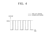
- FIG. 4 illustrates a control method of light sources, according to an exemplary embodiment.
- LED light-emitting diode
- an image scanning apparatus 1 includes a document table 20 on which a document 10 is placed and a frame 30 that is arranged so as to be reciprocally movable in directions indicated by a bidirectional arrow.
- the document table 20 may be formed of a transparent material such that it can transmit light emitted from a light source unit 110, as illustrated in Fig. 2 , therethrough.
- Fig. 2 illustrates a light guide unit 120 and a sensor unit 150 may be installed in a frame, e.g., frame 30.
- the light guide unit 120 may evenly diffuse light emitted from the light source unit 110 toward the document 10.
- the sensor unit 150 may sense image data from the document 10 by recognizing light that is reflected from the document 10 via diffusion.
- Fig. 2 illustrates a light source unit 110 including a first light source 112 and a second light source 114.
- the first light source 112 and the second light source 114 may be implemented as LEDs.
- the light source unit 110 may be connected to and controlled by a control unit 170.
- the light guide unit 120 includes a first light guide 122 and a second light guide 124.
- the first light source 112 may be installed at an end of the first light guide 122
- the second light source 114 may be installed at an end of the second light guide 124.
- the first light guide 122 and the second light guide 124 may be a predetermined distance apart from each other, and may be arranged in parallel with each other.
- a heat dissipation plate 190 may be installed in the frame 30, facing a light source unit, e.g., the light source unit 110.
- the heat dissipation plate 190 may reduce heat emitted from the light source unit 110. If the temperature of the light source unit 110 can be reduced, a large-size heat dissipation plate 190 may be no longer needed. In an exemplary embodiment, the heat dissipation plate 190 may be optional.
- An exemplary operation of the image scanning apparatus 1 includes that in response to the document 10 being placed on the document table 20, light may be emitted from the light source unit 110, and the light may be evenly diffused over the document 10 by the light guide unit 120.
- the sensor unit 150 may sense image data from the document 10 based on light reflected from the document 10, and the image scanning apparatus 1 may convert the image data into digital data.
- FIG. 3 A relationship between the temperature of heat generated by an LED and the turn-on duty of the LED is illustrated in FIG. 3 .
- the temperature of heat generated by an LED is proportional, e.g., directly proportional to the turn-on duty of the LED.
- the performance and the properties of an LED depend on the temperature of heat generated by the LED.
- a continuous use of a high-performance LED may inevitably lead to an increase in the temperature. Assuming that a 350 mA LED reaches a temperature of 100°C after a continuous turning on of the LED, the temperature of the LED may be reduced to 50°C by setting the turn-on duty of the LED to 50%.
- the temperature of the LED may decrease in inverse proportion to the turn-on duty of the LED.
- the temperature of the LED may also be reduced by reducing a current.
- the performance of the LED may deteriorate.
- a plurality of low-performance LEDs may be used, which, however, may result in an uneven emission of light and an increase in the manufacturing cost.
- the control unit 170 may alternately turn on the first light source 112 and the second light source 114 such that a turn-on period of the first light source 112 and a turn-on period of the second light source 114 do not overlap with each other. For example, if the first light source 112 and the second light source 114 both have a current of 500 mA, the control unit 170 may drive the first light source 112 and the second light source 114 with a current of 500 mA.
- the control unit 170 may alternately turn on the first light source 112 and the second light source 114 over the course of image scanning, to reduce the temperature of heat generated by the light source unit 110.
- the control unit 170 may control the second light source 114 to be turned off while the first light source 112 is turned on, and may control the first light source 112 to be turned off while the second light source 114 is turned on.
- the first light source 112 and the second light source 114 may be turned on or off alternately, and the turn-on duty cycle of the first light source 112 and the second light source 114 may be set to 50%.
- the light source unit 110 may undesirably appear to flicker.
- the first light source 112 and the second light source 114 may be implemented as LEDs.
- cold cathode fluorescent lamps (CCFLs) or xenon (Xe) lamps may be used as the first light source 112 and the second light source 114.
- CCFLs cold cathode fluorescent lamps
- Xe xenon lamps
- the first light source 112 and the second light source 114 may respond very slowly. Therefore, the first light source 112 and the second light source 114 may be implemented as LEDs, and particularly, high-performance LEDs.
- the control unit 170 may control the first light source 112 and the second light source 114 such that a uniform amount of light can be incident upon the sensor unit 150.
- the control unit 170 may control the light source unit 110 such that any irregularity in the amount of light incident upon the sensor unit 150 is less than 20%.
- the control unit 170 may control the frequency of the light source unit 110. The higher the frequency of the light source unit 110, the less likely the sensor unit 150 is to perceive a flicker. Thus, the control unit 170 may control the frequency of the light source unit 110 to be maintained within the range of about 50 kHz to about 200 kHz in consideration of the sensing speed of the sensor unit 150 and the response speed of the light source unit 110.
- a control method of an image scanning apparatus, according to an exemplary embodiment is described with reference to FIG. 5 .
- FIG. 5 illustrates a control method of an image scanning apparatus, according to an exemplary embodiment.
- the exemplary embodiment illustrated in FIG. 5 is similar to the exemplary embodiment illustrated in FIG. 4 , and thus, is described, focusing mainly on differences with the exemplary embodiment illustrated in FIG. 4 .
- the control unit 170 may control the turning on of the first light source 112 and the second light source 114 such that a turn-on period of the first light source 112 and a turn-on period of the second light source 114 can partially overlap with each other, as indicated by bidirectional arrows.
- the overlap period between the turn-on period of the first light source 112 and the turn-on period of the second light source 114 may be appropriately set between 0% and 100% in accordance with a target temperature.
- control unit 170 may control the turn-on duty cycle of the first light source 112 and the second light source 114 to be within the range of 50% to 100%.
- the turn-on duty cycle of the first light source 112 and the second light source 114 are both set to 80%, the temperature of the light source unit 110 may be reduced by 20%.
- the turn-on duty cycle of the first light source 112 and the second light source 114 are both set to 60%, the temperature of the light source unit 110 may be reduced by 40%. Therefore, according to the exemplary embodiment illustrated in FIG. 5 , it is possible to appropriately control the amount by which the temperature of the light source unit 110 should be reduced in consideration of the capability of the heat dissipation plate 190.
- control unit 170 may control the frequency of the light source unit 110 to be maintained within the range of about 50 kHz to about 200 kHz to prevent the light source unit 110 from flickering.
- An image scanning apparatus according to an exemplary embodiment is described with reference to FIG. 6 .
- FIG. 6 illustrates an image scanning apparatus according to an exemplary embodiment.
- the configuration of the image scanning apparatus illustrated in FIG. 6 is similar to the configuration of the image scanning apparatus 1 illustrated in FIG. 1 , and thus, the image scanning apparatus illustrated in FIG. 6 is described, focusing mainly on the differences with the image scanning apparatus 1 illustrated in FIG. 1 .
- the image scanning apparatus includes a light source unit 210, a light guide unit 220, and a control unit 270.
- the light source unit 210 includes a first light source 212 and a second light source 214.
- the first light source 212 and the second light source 214 may be installed at either end of the light guide unit 220.
- the first light source 212 and the second light source 214 may be connected to the control unit 270.
- the control unit 270 may alternately turn on the first light source 212 and the second light source 214 such that a turn-on period of the first light source 212 and a turn-on period of the second light source 214 do not overlap with each other, as described above with reference to FIG. 4 , or may alternately turn on the first light source 212 and the second light source 214 such that the turn-on period of the first light source 212 and the turn-on period of the second light source 214 partially overlap with each other, as described above with reference to FIG. 5 .
- control unit 270 may control the frequency of the light source unit 210 to be maintained within the range of about 50 kHz to about 200 kHz.
- the light guide unit 220 includes only one light guide, it is possible to reduce the size of the light guide unit 220 and the manufacturing cost of an image scanning apparatus.
- An image scanning apparatus according to an exemplary embodiment is described with reference to FIG. 7 .
- FIG. 7 illustrates an image scanning apparatus according to another exemplary embodiment.
- the configuration of the image scanning apparatus illustrated in FIG. 7 is similar to the configuration of the image scanning apparatus 1 illustrated in FIG. 1 , and thus, the image scanning apparatus illustrated in FIG. 7 is described, focusing mainly on the differences with the image scanning apparatus 1 illustrated in FIG. 1 .
- the image scanning apparatus includes a light source unit 310, a light guide unit 320, and a control unit 370.
- the light source unit 310 includes a first light source 312, a second light source 314, a third light source 316, and a fourth light source 318.
- the first light source 312, the second light source 314, the third light source 316, and the fourth light source 318 may all be connected to the control unit 370.
- the light guide unit 320 includes a first light guide 322 and a second light guide 324.
- the first light source 312 and the second light source 314 may be installed at either end of the first light guide 322.
- the third light source 316 and the fourth light source 318 may be installed at either end of the second light guide 324.
- control unit 370 may turn off the second light source 314 and the fourth light source 318 when turning on the first light source 312 and the third light source 316, and may turn on the second light source 314 and the fourth light source 318 when turning off the first light source 312 and the third light source 316.
- control unit 370 may turn off the second light source 314 and the third light source 316 when turning on the first light source 312 and the fourth light source 318, and may turn on the second light source 314 and the third light source 316 when turning off the first light source 312 and the fourth light source 318. That is, the control unit 370 may control the turning on or off of the light source unit 310 such that the light sources installed at one end of the light guide unit 320 are turned off when the light sources installed at the other end of the light guide unit 320 are turned on.
- the control unit 370 may control the turning on or off of the light source unit 310 such that turn-on periods of the first light source 312, the second light source 314, the third light source 316, and the fourth light source 318 partially overlap with one another.
- control unit 370 may control the frequency of the light source unit 310 to be maintained within the range of about 50 kHz to about 200 kHz.
Landscapes
- Engineering & Computer Science (AREA)
- Multimedia (AREA)
- Signal Processing (AREA)
- Physics & Mathematics (AREA)
- Optics & Photonics (AREA)
- Facsimile Scanning Arrangements (AREA)
- Light Sources And Details Of Projection-Printing Devices (AREA)
- Image Input (AREA)
Abstract
Description
- This application is related to and claims priority to Korean Patent Application No.
10-2011-0120930, filed on November 18, 2011 - The embodiments discussed herein relate to an image scanning apparatus and a control method thereof.
- An image scanning apparatus is an apparatus that scans an original image such as a document, a picture or a film, and converts the scanned image into digital data. The digital data may be shown on a computer monitor or printed out by a printer and be generated as an output image. Such an image scanning apparatus may be a scanner, copier, facsimile, or an MFP (Multi Function Peripheral) where the functions of a scanner, copier and facsimile are integrated in one apparatus.
- An image scanning apparatus uses a light source for emitting light for performing scanning. For example, cold cathode fluorescent lamps (CCFLs), xenon (Xe) lamps, or light-emitting diodes (LEDs) may be used as the light source.
- Due to the risks posed to the environment by CCFLs or Xe lamps and the shortcomings of CCFLs or Xe lamps such as low efficiency and high power consumption, LEDs are becoming more widely employed as light sources for image scanning apparatuses.
- The temperature of LEDs gradually increases as the LEDs emit light. Since the performance and lifetime of LEDs depend on the temperature of the LEDs, a heat dissipation plate may be provided in an image scanning apparatus using LEDs as light sources. The size of the heat dissipation plate may be determined by the amount of heat to dissipate from the LEDs. Accordingly, in the case of using high-performance LEDs, a large-size heat dissipation plate may be needed to adequately dissipate heat. However, the use of a large-size heat dissipation plate may lead to an increase in the manufacturing cost of an image scanning apparatus, and it is difficult to secure enough space for accommodating a large-size heat dissipation plate in an image scanning apparatus.
- To address these problems, an array of a plurality of low-performance LEDs may be used as a light source for an image scanning apparatus. However, the low-performance LEDs may not be able to uniformly emit light, and also may contribute to an increase in the manufacturing cost of an image scanning apparatus.
- Additional aspects and/or advantages will be set forth in part in the description which follows and, in part, will be apparent from the description, or may be learned by practice of the invention.
- An exemplary embodiment may address at least the above problems and/or disadvantages and other disadvantages not described above.
- An exemplary embodiment provides an image scanning apparatus and a control method thereof.
- According to an aspect of the exemplary embodiment, an image scanning apparatus is provided that scans an image of a document and converts the scanned image into digital data, the image scanning apparatus including, a plurality of light sources that emit light, a light guide unit that diffuses the light emitted by the light sources, a sensor unit that senses image data from the document by recognizing light reflected from the document by being diffused by the light guide unit, and a control unit that controls the turning on of the light sources, wherein the control unit alternately turns on or off the light sources such that at least one of the light sources is turned on when at least one other light source is turned off.
- The control unit may control a turn-on duty of each of the light sources to be at least 50% or higher.
- The control unit may control a frequency of each of the light sources to be within a range of about 50 kHz to about 200 kHz.
- The light guide unit may include a first light guide and a second light guide.
- The light sources may include at least one light source installed at one end of the first light guide and at least one light source installed at one end of the second light guide.
- The light sources may include a first light source and a second light source.
- The first light source may be installed at one end of the first light guide and the second light source may be installed at one end of the second light guide.
- The control unit may control the first light source and the second light source to be alternately turned on.
- The control unit may control the first light source and the second light source such that a turn-on period of the first light source and a turn-on period of the second light source partially overlap with each other.
- The light sources may be light-emitting diodes (LEDs).
- According to another aspect of the an exemplary embodiment, there is provided a control method of an image scanning apparatus which scans an image of a document and converts the scanned image into digital data, the control method including: emitting light by turning on a plurality of light sources; sensing image data from the document by recognizing light reflected from the document by being diffused; and converting the image data into digital data, wherein the turning on the light sources comprises alternately turning on or off the light sources such that at least one of the light sources is turned on when at least one other light source is turned off.
- The turning on the light sources may also include controlling a turn-on duty of each of the light sources to be at least 50% or higher.
- The turning on the light sources may also include controlling a frequency of each of the light sources to be within a range of about 50 kHz to about 200 kHz.
- The turning on the light sources further may include controlling the light sources such that turn-on periods of the light sources do not overlap with each another.
- The turning on the light sources may also include controlling the light sources such that turn-on periods of the light sources partially overlap with each another.
- The light sources may be LEDs.
- The above and/or other aspects will be more apparent by describing certain exemplary embodiments with reference to the accompanying drawings, in which:
-
FIG. 1 illustrates an image scanning apparatus according to an exemplary embodiment; -
FIG. 2 illustrates an example of the structure of the image scanning apparatus illustrated inFIG. 1 , according to an exemplary embodiment; -
FIG. 3 illustrates an example of the relationship between the turn-on duty of a light-emitting diode (LED) and the temperature of heat generated by the LED; -
FIG. 4 illustrates a control method of light sources, according to an exemplary embodiment; -
FIG. 5 illustrates a control method of light sources, according to an exemplary embodiment; -
FIG. 6 illustrates an image scanning apparatus according to an exemplary embodiment; and -
FIG. 7 illustrates an image scanning apparatus according to an exemplary embodiment. - Exemplary embodiments are described in greater detail with reference to the accompanying drawings.
- In the following description, the same drawing reference numerals are used for similar elements even in different drawings. The matters defined in the description, such as detailed construction and elements, are provided to assist in a comprehensive understanding of the exemplary embodiments. However, an exemplary embodiment can be carried out without those specifically defined matters.
-
FIG. 1 is a schematic diagram illustrating an image scanning apparatus according to an exemplary embodiment,FIG. 2 illustrates an example of the structure of the image scanning apparatus illustrated inFIG. 1 , according to an exemplary embodiment,FIG. 3 illustrates an example of the relationship between the turn-on duty of a light-emitting diode (LED) and the temperature of heat generated by the LED, andFIG. 4 illustrates a control method of light sources, according to an exemplary embodiment. - Referring to
FIG. 1 , animage scanning apparatus 1 includes a document table 20 on which adocument 10 is placed and aframe 30 that is arranged so as to be reciprocally movable in directions indicated by a bidirectional arrow. - The document table 20 may be formed of a transparent material such that it can transmit light emitted from a
light source unit 110, as illustrated inFig. 2 , therethrough. -
Fig. 2 illustrates alight guide unit 120 and asensor unit 150 may be installed in a frame, e.g.,frame 30. Thelight guide unit 120 may evenly diffuse light emitted from thelight source unit 110 toward thedocument 10. Thesensor unit 150 may sense image data from thedocument 10 by recognizing light that is reflected from thedocument 10 via diffusion. -
Fig. 2 illustrates alight source unit 110 including afirst light source 112 and asecond light source 114. Thefirst light source 112 and thesecond light source 114 may be implemented as LEDs. - The
light source unit 110 may be connected to and controlled by acontrol unit 170. - The
light guide unit 120 includes afirst light guide 122 and asecond light guide 124. Thefirst light source 112 may be installed at an end of thefirst light guide 122, and thesecond light source 114 may be installed at an end of thesecond light guide 124. Thefirst light guide 122 and thesecond light guide 124 may be a predetermined distance apart from each other, and may be arranged in parallel with each other. - As illustrated in
Fig. 1 , aheat dissipation plate 190 may be installed in theframe 30, facing a light source unit, e.g., thelight source unit 110. - The
heat dissipation plate 190 may reduce heat emitted from thelight source unit 110. If the temperature of thelight source unit 110 can be reduced, a large-sizeheat dissipation plate 190 may be no longer needed. In an exemplary embodiment, theheat dissipation plate 190 may be optional. - An exemplary operation of the
image scanning apparatus 1 includes that in response to thedocument 10 being placed on the document table 20, light may be emitted from thelight source unit 110, and the light may be evenly diffused over thedocument 10 by thelight guide unit 120. Thesensor unit 150 may sense image data from thedocument 10 based on light reflected from thedocument 10, and theimage scanning apparatus 1 may convert the image data into digital data. - A relationship between the temperature of heat generated by an LED and the turn-on duty of the LED is illustrated in
FIG. 3 . Referring toFIG. 3 , the temperature of heat generated by an LED is proportional, e.g., directly proportional to the turn-on duty of the LED. The performance and the properties of an LED (for example, brightness, color gamut, and lifetime) depend on the temperature of heat generated by the LED. A continuous use of a high-performance LED may inevitably lead to an increase in the temperature. Assuming that a 350 mA LED reaches a temperature of 100°C after a continuous turning on of the LED, the temperature of the LED may be reduced to 50°C by setting the turn-on duty of the LED to 50%. When an LED is turned on or off at intervals of 10 microseconds, i.e., when the LED is turned on for five microseconds and then turned off for five microseconds repeatedly, the temperature of the LED may decrease in inverse proportion to the turn-on duty of the LED. The temperature of the LED may also be reduced by reducing a current. In this example, however, the performance of the LED may deteriorate. To address this problem, a plurality of low-performance LEDs may be used, which, however, may result in an uneven emission of light and an increase in the manufacturing cost. - An exemplary control method of a light source unit, e.g.,
light source unit 110 of theimage scanning apparatus 1 is described. - In a case in which the
light source unit 110 needs to be turned on for performing image scanning on thedocument 10, thecontrol unit 170 may alternately turn on the firstlight source 112 and the secondlight source 114 such that a turn-on period of the firstlight source 112 and a turn-on period of the secondlight source 114 do not overlap with each other. For example, if the firstlight source 112 and the secondlight source 114 both have a current of 500 mA, thecontrol unit 170 may drive the firstlight source 112 and the secondlight source 114 with a current of 500 mA. Since the current of thelight source unit 110 is inversely proportional to the temperature of heat generated by thelight source unit 110, thecontrol unit 170 may alternately turn on the firstlight source 112 and the secondlight source 114 over the course of image scanning, to reduce the temperature of heat generated by thelight source unit 110. For example, referring toFIG. 4 , thecontrol unit 170 may control the secondlight source 114 to be turned off while the firstlight source 112 is turned on, and may control the firstlight source 112 to be turned off while the secondlight source 114 is turned on. For example, the firstlight source 112 and the secondlight source 114 may be turned on or off alternately, and the turn-on duty cycle of the firstlight source 112 and the secondlight source 114 may be set to 50%. If the turn-on duty cycle of the firstlight source 112 and the secondlight source 114 are both below 50%, i.e., if the firstlight source 112 and the secondlight source 114 are turned off for more than 50% of a total light source turn-on period for performing image scanning, thelight source unit 110 may undesirably appear to flicker. - For example, the first
light source 112 and the secondlight source 114 may be implemented as LEDs. Alternatively, cold cathode fluorescent lamps (CCFLs) or xenon (Xe) lamps may be used as the firstlight source 112 and the secondlight source 114. In the latter example, however, the firstlight source 112 and the secondlight source 114 may respond very slowly. Therefore, the firstlight source 112 and the secondlight source 114 may be implemented as LEDs, and particularly, high-performance LEDs. - The
control unit 170 may control the firstlight source 112 and the secondlight source 114 such that a uniform amount of light can be incident upon thesensor unit 150. When an irregularity in the amount of light incident upon thesensor unit 150 is greater than 20%, the quality of an image may deteriorate. Accordingly, thecontrol unit 170 may control thelight source unit 110 such that any irregularity in the amount of light incident upon thesensor unit 150 is less than 20%. - Due to an improper turning or off of the first
light source 112 and the secondlight source 114, a period during which no light is incident upon thesensor unit 150 may be encountered. In this example, the amount of light incident upon thesensor unit 150 may decrease. Alternatively, in a case in which the firstlight source 112 and the secondlight source 114 are turned on or off at a low frequency, thesensor unit 150 may determine thelight source unit 110 as flickering, which adversely affects the quality of an image. To prevent thelight source unit 110 from flickering, thecontrol unit 170 may control the frequency of thelight source unit 110. The higher the frequency of thelight source unit 110, the less likely thesensor unit 150 is to perceive a flicker. Thus, thecontrol unit 170 may control the frequency of thelight source unit 110 to be maintained within the range of about 50 kHz to about 200 kHz in consideration of the sensing speed of thesensor unit 150 and the response speed of thelight source unit 110. - A control method of an image scanning apparatus, according to an exemplary embodiment is described with reference to
FIG. 5 . -
FIG. 5 illustrates a control method of an image scanning apparatus, according to an exemplary embodiment. The exemplary embodiment illustrated inFIG. 5 is similar to the exemplary embodiment illustrated inFIG. 4 , and thus, is described, focusing mainly on differences with the exemplary embodiment illustrated inFIG. 4 . - Referring to
FIG. 5 , thecontrol unit 170 may control the turning on of the firstlight source 112 and the secondlight source 114 such that a turn-on period of the firstlight source 112 and a turn-on period of the secondlight source 114 can partially overlap with each other, as indicated by bidirectional arrows. In this example, the overlap period between the turn-on period of the firstlight source 112 and the turn-on period of the secondlight source 114 may be appropriately set between 0% and 100% in accordance with a target temperature. - In the exemplary embodiment illustrated in
FIG. 5 , thecontrol unit 170 may control the turn-on duty cycle of the firstlight source 112 and the secondlight source 114 to be within the range of 50% to 100%. - According to the exemplary embodiment illustrated in
FIG. 5 , it is possible to appropriately set the turn-on duty of a light source within a given range and thus to reduce the temperature of the light source. For example, if the turn-on duty cycle of the firstlight source 112 and the secondlight source 114 are both set to 80%, the temperature of thelight source unit 110 may be reduced by 20%. Alternatively, if the turn-on duty cycle of the firstlight source 112 and the secondlight source 114 are both set to 60%, the temperature of thelight source unit 110 may be reduced by 40%. Therefore, according to the exemplary embodiment illustrated inFIG. 5 , it is possible to appropriately control the amount by which the temperature of thelight source unit 110 should be reduced in consideration of the capability of theheat dissipation plate 190. In addition, by appropriately adjusting the turn-on duty cycle of the firstlight source 112 and the secondlight source 114 with the aid of thecontrol unit 170, it is possible to make theheat dissipation plate 190 optional or reduce the size of theheat dissipation plate 190. - In the exemplary embodiment illustrated in
FIG. 5 , as in the exemplary embodiment illustrated inFIG. 4 , thecontrol unit 170 may control the frequency of thelight source unit 110 to be maintained within the range of about 50 kHz to about 200 kHz to prevent thelight source unit 110 from flickering. - An image scanning apparatus according to an exemplary embodiment is described with reference to
FIG. 6 . -
FIG. 6 illustrates an image scanning apparatus according to an exemplary embodiment. The configuration of the image scanning apparatus illustrated inFIG. 6 is similar to the configuration of theimage scanning apparatus 1 illustrated inFIG. 1 , and thus, the image scanning apparatus illustrated inFIG. 6 is described, focusing mainly on the differences with theimage scanning apparatus 1 illustrated inFIG. 1 . - Referring to
FIG. 6 , the image scanning apparatus includes alight source unit 210, alight guide unit 220, and acontrol unit 270. - The
light source unit 210 includes a firstlight source 212 and a secondlight source 214. The firstlight source 212 and the secondlight source 214 may be installed at either end of thelight guide unit 220. - The first
light source 212 and the secondlight source 214 may be connected to thecontrol unit 270. - The
control unit 270 may alternately turn on the firstlight source 212 and the secondlight source 214 such that a turn-on period of the firstlight source 212 and a turn-on period of the secondlight source 214 do not overlap with each other, as described above with reference toFIG. 4 , or may alternately turn on the firstlight source 212 and the secondlight source 214 such that the turn-on period of the firstlight source 212 and the turn-on period of the secondlight source 214 partially overlap with each other, as described above with reference toFIG. 5 . - To prevent the
light source unit 210 from flickering, thecontrol unit 270 may control the frequency of thelight source unit 210 to be maintained within the range of about 50 kHz to about 200 kHz. - Since the
light guide unit 220 includes only one light guide, it is possible to reduce the size of thelight guide unit 220 and the manufacturing cost of an image scanning apparatus. - An image scanning apparatus according to an exemplary embodiment is described with reference to
FIG. 7 . -
FIG. 7 illustrates an image scanning apparatus according to another exemplary embodiment. The configuration of the image scanning apparatus illustrated inFIG. 7 is similar to the configuration of theimage scanning apparatus 1 illustrated inFIG. 1 , and thus, the image scanning apparatus illustrated inFIG. 7 is described, focusing mainly on the differences with theimage scanning apparatus 1 illustrated inFIG. 1 . - Referring to
FIG. 7 , the image scanning apparatus includes alight source unit 310, alight guide unit 320, and acontrol unit 370. Thelight source unit 310 includes a firstlight source 312, a secondlight source 314, a thirdlight source 316, and a fourthlight source 318. - The first
light source 312, the secondlight source 314, the thirdlight source 316, and the fourthlight source 318 may all be connected to thecontrol unit 370. - The
light guide unit 320 includes afirst light guide 322 and a secondlight guide 324. - The first
light source 312 and the secondlight source 314 may be installed at either end of thefirst light guide 322. - The third
light source 316 and the fourthlight source 318 may be installed at either end of the secondlight guide 324. - For example, the
control unit 370 may turn off the secondlight source 314 and the fourthlight source 318 when turning on the firstlight source 312 and the thirdlight source 316, and may turn on the secondlight source 314 and the fourthlight source 318 when turning off the firstlight source 312 and the thirdlight source 316. Alternatively, thecontrol unit 370 may turn off the secondlight source 314 and the thirdlight source 316 when turning on the firstlight source 312 and the fourthlight source 318, and may turn on the secondlight source 314 and the thirdlight source 316 when turning off the firstlight source 312 and the fourthlight source 318. That is, thecontrol unit 370 may control the turning on or off of thelight source unit 310 such that the light sources installed at one end of thelight guide unit 320 are turned off when the light sources installed at the other end of thelight guide unit 320 are turned on. - The
control unit 370 may control the turning on or off of thelight source unit 310 such that turn-on periods of the firstlight source 312, the secondlight source 314, the thirdlight source 316, and the fourthlight source 318 partially overlap with one another. - To prevent the
light source unit 310 from flickering, thecontrol unit 370 may control the frequency of thelight source unit 310 to be maintained within the range of about 50 kHz to about 200 kHz. - Although a few embodiments have been shown and described, it would be appreciated by those skilled in the art that changes may be made in these embodiments without departing from the principles and spirit of the invention, the scope of which is defined in the claims and their equivalents.
Claims (15)
- An image scanning apparatus that scans an image of a document and converts the scanned image into digital data, the image scanning apparatus comprising:a plurality of light sources that emit light;a light guide unit that diffuses the light emitted by the light sources;a sensor unit that senses image data from the document by recognizing light reflected from the document by being diffused by the light guide unit; anda control unit that controls the turning on of the light sources,wherein the control unit alternately turns on or off the light sources such that at least one of the plurality of light sources is turned on when at least one other light source of the plurality of light sources is turned off.
- The image scanning apparatus of claim 1, wherein the control unit controls a turn-on duty of each of the light sources to be at least 50% or higher.
- The image scanning apparatus of claim 2, wherein the control unit controls a frequency of each of the light sources to be within a range of about 50 kHz to about 200 kHz.
- The image scanning apparatus of claim 3, wherein the light guide unit comprises a first light guide and a second light guide.
- The image scanning apparatus of claim 4, wherein the light sources comprise at least one light source installed at one end of the first light guide and at least one light source installed at one end of the second light guide.
- The image scanning apparatus of claim 4, wherein the light sources comprise a first light source and a second light source.
- The image scanning apparatus of claim 6, wherein the first light source is installed at one end of the first light guide and the second light source is installed at one end of the second light guide.
- The image scanning apparatus of claim 7, wherein the control unit controls the first light source and the second light source to be alternately turned on.
- The image scanning apparatus of claim 7, wherein the control unit controls the first light source and the second light source such that a turn-on period of the first light source and a turn-on period of the second light source partially overlap with each other.
- The image scanning apparatus of claim 1, wherein the light sources are light-emitting diodes (LEDs).
- A control method of an image scanning apparatus that scans an image of a document and converts the scanned image into digital data, the control method comprising:emitting light by turning on a plurality of light sources;sensing image data from the document by recognizing light reflected from the document by being diffused; andconverting the image data into digital data,wherein the turning on the light sources comprises alternately turning on or off the light sources such that at least one light source of the plurality of light sources is turned on when at least one other light source of the plurality of light sources is turned off.
- The control method of claim 11, wherein the turning on the light sources further comprises controlling a turn-on duty of each of the light sources to be at least 50% or higher.
- The control method of claim 11, wherein the turning on the light sources further comprises controlling a frequency of each of the light sources to be within a range of about 50 kHz to about 200 kHz.
- The control method of claim 11, wherein the turning on the light sources further comprises controlling the light sources such that turn-on periods of the light sources do not overlap with each another.
- The control method of claim 11, wherein the turning on the light sources further comprises controlling the light sources such that turn-on periods of the light sources partially overlap with each another.
Applications Claiming Priority (1)
| Application Number | Priority Date | Filing Date | Title |
|---|---|---|---|
| KR1020110120930A KR101883315B1 (en) | 2011-11-18 | 2011-11-18 | Image scanning apparatus and control method thereof |
Publications (3)
| Publication Number | Publication Date |
|---|---|
| EP2595371A2 true EP2595371A2 (en) | 2013-05-22 |
| EP2595371A3 EP2595371A3 (en) | 2013-06-26 |
| EP2595371B1 EP2595371B1 (en) | 2018-07-11 |
Family
ID=47262991
Family Applications (1)
| Application Number | Title | Priority Date | Filing Date |
|---|---|---|---|
| EP12186118.1A Active EP2595371B1 (en) | 2011-11-18 | 2012-09-26 | Image scanning apparatus and control method thereof |
Country Status (3)
| Country | Link |
|---|---|
| US (1) | US9001394B2 (en) |
| EP (1) | EP2595371B1 (en) |
| KR (1) | KR101883315B1 (en) |
Families Citing this family (5)
| Publication number | Priority date | Publication date | Assignee | Title |
|---|---|---|---|---|
| EP2067119A2 (en) * | 2006-09-08 | 2009-06-10 | Exbiblio B.V. | Optical scanners, such as hand-held optical scanners |
| CA2886782C (en) | 2012-10-05 | 2020-03-10 | Inguran, Llc | High efficiency methods of sex sorting sperm |
| JP5860854B2 (en) * | 2013-08-22 | 2016-02-16 | 京セラドキュメントソリューションズ株式会社 | Image reading apparatus and image forming apparatus having the same |
| JP6579863B2 (en) * | 2015-08-27 | 2019-09-25 | キヤノン・コンポーネンツ株式会社 | Reader and transmission light source unit |
| KR20210048082A (en) * | 2019-10-23 | 2021-05-03 | 휴렛-팩커드 디벨롭먼트 컴퍼니, 엘.피. | Lightguide type illumination device with symmetrically arranged multiple color light sources |
Family Cites Families (11)
| Publication number | Priority date | Publication date | Assignee | Title |
|---|---|---|---|---|
| JPS60197063A (en) | 1984-03-21 | 1985-10-05 | Canon Inc | Led array and its sectional lighting method |
| JPH0290862A (en) * | 1988-09-28 | 1990-03-30 | Eastman Kodatsuku Japan Kk | Information reader |
| US5457623A (en) * | 1993-07-06 | 1995-10-10 | Shafrir Romano | High efficiency power converter having diode-controlled switching frequency for illumination loads |
| JPH09200438A (en) | 1996-01-19 | 1997-07-31 | Canon Inc | Image reading device |
| JP3423572B2 (en) | 1996-06-06 | 2003-07-07 | キヤノン株式会社 | Image reading system, its control device, image reading method, and storage medium |
| TW503646B (en) | 2000-03-16 | 2002-09-21 | Nippon Sheet Glass Co Ltd | Line illuminating device |
| JP5200360B2 (en) * | 2006-09-29 | 2013-06-05 | 富士ゼロックス株式会社 | Exposure apparatus and image forming apparatus |
| EP2395738B1 (en) * | 2007-07-31 | 2016-03-23 | Samsung Electronics Co., Ltd. | Multi-functional device having scanner module and image scanning apparatus employing the scanner module |
| JP4609531B2 (en) * | 2008-06-11 | 2011-01-12 | 三菱電機株式会社 | Image reading device |
| JP4609530B2 (en) * | 2008-06-11 | 2011-01-12 | 三菱電機株式会社 | Image reading device |
| JP5573107B2 (en) * | 2009-11-04 | 2014-08-20 | ウシオ電機株式会社 | Lighting device |
-
2011
- 2011-11-18 KR KR1020110120930A patent/KR101883315B1/en not_active Expired - Fee Related
-
2012
- 2012-04-23 US US13/453,633 patent/US9001394B2/en active Active
- 2012-09-26 EP EP12186118.1A patent/EP2595371B1/en active Active
Non-Patent Citations (1)
| Title |
|---|
| None |
Also Published As
| Publication number | Publication date |
|---|---|
| KR20130055270A (en) | 2013-05-28 |
| US9001394B2 (en) | 2015-04-07 |
| US20130128322A1 (en) | 2013-05-23 |
| KR101883315B1 (en) | 2018-08-01 |
| EP2595371B1 (en) | 2018-07-11 |
| EP2595371A3 (en) | 2013-06-26 |
Similar Documents
| Publication | Publication Date | Title |
|---|---|---|
| EP2595371B1 (en) | Image scanning apparatus and control method thereof | |
| CN101682961B (en) | Lighting device and liquid crystal display device | |
| CN101161036B (en) | Lighting device and display device using same | |
| CN101059609A (en) | Method for driving liquid crystal display assembly | |
| JP4757585B2 (en) | Light source unit and lighting device | |
| CN1847956A (en) | Illumination system and display device using the same | |
| CN101335813B (en) | Image reading device and control method thereof | |
| CN1697999A (en) | Backlight, backlight drive equipment, display equipment | |
| CN1866108A (en) | Backlight unit and liquid crystal display employing the same | |
| CN101044427A (en) | Heat radiator and display unit | |
| CN1975534A (en) | Backlight driving device, backlight assembly, liquid crystal display device, and backlight driving method | |
| CN1791298A (en) | Lighting device, liquid crystal display device, mobile terminal device and its controlling method | |
| JP2017091866A (en) | Light emitting device | |
| CN101102386A (en) | Image reading device, image reading method | |
| CN1955795A (en) | Display apparatus having led backlight and brightness adjusting method for the same | |
| JP2013092732A (en) | Backlight device, image display device and method for controlling backlight device | |
| JP5302599B2 (en) | Backlight device | |
| TWI395976B (en) | Light projection device of scanner module and light arrangement method thereof | |
| CN102238310B (en) | Image read-out | |
| JP5767482B2 (en) | Illumination device and image reading device | |
| JP5302598B2 (en) | Backlight device | |
| US20120002249A1 (en) | Image scanning apparatus to alternate scanning and method thereof | |
| JP4091712B2 (en) | Image reading device | |
| CN220586332U (en) | Infrared cutting optical module and scanner using same | |
| JP2006054778A (en) | Picture reader |
Legal Events
| Date | Code | Title | Description |
|---|---|---|---|
| PUAI | Public reference made under article 153(3) epc to a published international application that has entered the european phase |
Free format text: ORIGINAL CODE: 0009012 |
|
| AK | Designated contracting states |
Kind code of ref document: A2 Designated state(s): AL AT BE BG CH CY CZ DE DK EE ES FI FR GB GR HR HU IE IS IT LI LT LU LV MC MK MT NL NO PL PT RO RS SE SI SK SM TR |
|
| AX | Request for extension of the european patent |
Extension state: BA ME |
|
| PUAL | Search report despatched |
Free format text: ORIGINAL CODE: 0009013 |
|
| AK | Designated contracting states |
Kind code of ref document: A3 Designated state(s): AL AT BE BG CH CY CZ DE DK EE ES FI FR GB GR HR HU IE IS IT LI LT LU LV MC MK MT NL NO PL PT RO RS SE SI SK SM TR |
|
| AX | Request for extension of the european patent |
Extension state: BA ME |
|
| RIC1 | Information provided on ipc code assigned before grant |
Ipc: H04N 1/028 20060101AFI20130523BHEP |
|
| 17P | Request for examination filed |
Effective date: 20131213 |
|
| RBV | Designated contracting states (corrected) |
Designated state(s): AL AT BE BG CH CY CZ DE DK EE ES FI FR GB GR HR HU IE IS IT LI LT LU LV MC MK MT NL NO PL PT RO RS SE SI SK SM TR |
|
| STAA | Information on the status of an ep patent application or granted ep patent |
Free format text: STATUS: EXAMINATION IS IN PROGRESS |
|
| 17Q | First examination report despatched |
Effective date: 20161213 |
|
| RAP1 | Party data changed (applicant data changed or rights of an application transferred) |
Owner name: S-PRINTING SOLUTION CO., LTD. |
|
| GRAP | Despatch of communication of intention to grant a patent |
Free format text: ORIGINAL CODE: EPIDOSNIGR1 |
|
| STAA | Information on the status of an ep patent application or granted ep patent |
Free format text: STATUS: GRANT OF PATENT IS INTENDED |
|
| INTG | Intention to grant announced |
Effective date: 20180131 |
|
| GRAS | Grant fee paid |
Free format text: ORIGINAL CODE: EPIDOSNIGR3 |
|
| GRAA | (expected) grant |
Free format text: ORIGINAL CODE: 0009210 |
|
| STAA | Information on the status of an ep patent application or granted ep patent |
Free format text: STATUS: THE PATENT HAS BEEN GRANTED |
|
| RAP1 | Party data changed (applicant data changed or rights of an application transferred) |
Owner name: HP PRINTING KOREA CO., LTD. |
|
| AK | Designated contracting states |
Kind code of ref document: B1 Designated state(s): AL AT BE BG CH CY CZ DE DK EE ES FI FR GB GR HR HU IE IS IT LI LT LU LV MC MK MT NL NO PL PT RO RS SE SI SK SM TR |
|
| REG | Reference to a national code |
Ref country code: GB Ref legal event code: FG4D |
|
| REG | Reference to a national code |
Ref country code: CH Ref legal event code: EP |
|
| REG | Reference to a national code |
Ref country code: AT Ref legal event code: REF Ref document number: 1018155 Country of ref document: AT Kind code of ref document: T Effective date: 20180715 |
|
| REG | Reference to a national code |
Ref country code: IE Ref legal event code: FG4D |
|
| REG | Reference to a national code |
Ref country code: DE Ref legal event code: R096 Ref document number: 602012048309 Country of ref document: DE |
|
| REG | Reference to a national code |
Ref country code: FR Ref legal event code: PLFP Year of fee payment: 7 |
|
| REG | Reference to a national code |
Ref country code: NL Ref legal event code: MP Effective date: 20180711 |
|
| REG | Reference to a national code |
Ref country code: LT Ref legal event code: MG4D |
|
| REG | Reference to a national code |
Ref country code: AT Ref legal event code: MK05 Ref document number: 1018155 Country of ref document: AT Kind code of ref document: T Effective date: 20180711 |
|
| PG25 | Lapsed in a contracting state [announced via postgrant information from national office to epo] |
Ref country code: NL Free format text: LAPSE BECAUSE OF FAILURE TO SUBMIT A TRANSLATION OF THE DESCRIPTION OR TO PAY THE FEE WITHIN THE PRESCRIBED TIME-LIMIT Effective date: 20180711 |
|
| PG25 | Lapsed in a contracting state [announced via postgrant information from national office to epo] |
Ref country code: BG Free format text: LAPSE BECAUSE OF FAILURE TO SUBMIT A TRANSLATION OF THE DESCRIPTION OR TO PAY THE FEE WITHIN THE PRESCRIBED TIME-LIMIT Effective date: 20181011 Ref country code: PL Free format text: LAPSE BECAUSE OF FAILURE TO SUBMIT A TRANSLATION OF THE DESCRIPTION OR TO PAY THE FEE WITHIN THE PRESCRIBED TIME-LIMIT Effective date: 20180711 Ref country code: LT Free format text: LAPSE BECAUSE OF FAILURE TO SUBMIT A TRANSLATION OF THE DESCRIPTION OR TO PAY THE FEE WITHIN THE PRESCRIBED TIME-LIMIT Effective date: 20180711 Ref country code: RS Free format text: LAPSE BECAUSE OF FAILURE TO SUBMIT A TRANSLATION OF THE DESCRIPTION OR TO PAY THE FEE WITHIN THE PRESCRIBED TIME-LIMIT Effective date: 20180711 Ref country code: AT Free format text: LAPSE BECAUSE OF FAILURE TO SUBMIT A TRANSLATION OF THE DESCRIPTION OR TO PAY THE FEE WITHIN THE PRESCRIBED TIME-LIMIT Effective date: 20180711 Ref country code: IS Free format text: LAPSE BECAUSE OF FAILURE TO SUBMIT A TRANSLATION OF THE DESCRIPTION OR TO PAY THE FEE WITHIN THE PRESCRIBED TIME-LIMIT Effective date: 20181111 Ref country code: GR Free format text: LAPSE BECAUSE OF FAILURE TO SUBMIT A TRANSLATION OF THE DESCRIPTION OR TO PAY THE FEE WITHIN THE PRESCRIBED TIME-LIMIT Effective date: 20181012 Ref country code: NO Free format text: LAPSE BECAUSE OF FAILURE TO SUBMIT A TRANSLATION OF THE DESCRIPTION OR TO PAY THE FEE WITHIN THE PRESCRIBED TIME-LIMIT Effective date: 20181011 Ref country code: SE Free format text: LAPSE BECAUSE OF FAILURE TO SUBMIT A TRANSLATION OF THE DESCRIPTION OR TO PAY THE FEE WITHIN THE PRESCRIBED TIME-LIMIT Effective date: 20180711 Ref country code: FI Free format text: LAPSE BECAUSE OF FAILURE TO SUBMIT A TRANSLATION OF THE DESCRIPTION OR TO PAY THE FEE WITHIN THE PRESCRIBED TIME-LIMIT Effective date: 20180711 |
|
| PG25 | Lapsed in a contracting state [announced via postgrant information from national office to epo] |
Ref country code: ES Free format text: LAPSE BECAUSE OF FAILURE TO SUBMIT A TRANSLATION OF THE DESCRIPTION OR TO PAY THE FEE WITHIN THE PRESCRIBED TIME-LIMIT Effective date: 20180711 Ref country code: HR Free format text: LAPSE BECAUSE OF FAILURE TO SUBMIT A TRANSLATION OF THE DESCRIPTION OR TO PAY THE FEE WITHIN THE PRESCRIBED TIME-LIMIT Effective date: 20180711 Ref country code: AL Free format text: LAPSE BECAUSE OF FAILURE TO SUBMIT A TRANSLATION OF THE DESCRIPTION OR TO PAY THE FEE WITHIN THE PRESCRIBED TIME-LIMIT Effective date: 20180711 Ref country code: LV Free format text: LAPSE BECAUSE OF FAILURE TO SUBMIT A TRANSLATION OF THE DESCRIPTION OR TO PAY THE FEE WITHIN THE PRESCRIBED TIME-LIMIT Effective date: 20180711 |
|
| REG | Reference to a national code |
Ref country code: DE Ref legal event code: R097 Ref document number: 602012048309 Country of ref document: DE |
|
| PG25 | Lapsed in a contracting state [announced via postgrant information from national office to epo] |
Ref country code: EE Free format text: LAPSE BECAUSE OF FAILURE TO SUBMIT A TRANSLATION OF THE DESCRIPTION OR TO PAY THE FEE WITHIN THE PRESCRIBED TIME-LIMIT Effective date: 20180711 Ref country code: MC Free format text: LAPSE BECAUSE OF FAILURE TO SUBMIT A TRANSLATION OF THE DESCRIPTION OR TO PAY THE FEE WITHIN THE PRESCRIBED TIME-LIMIT Effective date: 20180711 Ref country code: CZ Free format text: LAPSE BECAUSE OF FAILURE TO SUBMIT A TRANSLATION OF THE DESCRIPTION OR TO PAY THE FEE WITHIN THE PRESCRIBED TIME-LIMIT Effective date: 20180711 Ref country code: IT Free format text: LAPSE BECAUSE OF FAILURE TO SUBMIT A TRANSLATION OF THE DESCRIPTION OR TO PAY THE FEE WITHIN THE PRESCRIBED TIME-LIMIT Effective date: 20180711 Ref country code: RO Free format text: LAPSE BECAUSE OF FAILURE TO SUBMIT A TRANSLATION OF THE DESCRIPTION OR TO PAY THE FEE WITHIN THE PRESCRIBED TIME-LIMIT Effective date: 20180711 |
|
| REG | Reference to a national code |
Ref country code: CH Ref legal event code: PL |
|
| PLBE | No opposition filed within time limit |
Free format text: ORIGINAL CODE: 0009261 |
|
| STAA | Information on the status of an ep patent application or granted ep patent |
Free format text: STATUS: NO OPPOSITION FILED WITHIN TIME LIMIT |
|
| PG25 | Lapsed in a contracting state [announced via postgrant information from national office to epo] |
Ref country code: SM Free format text: LAPSE BECAUSE OF FAILURE TO SUBMIT A TRANSLATION OF THE DESCRIPTION OR TO PAY THE FEE WITHIN THE PRESCRIBED TIME-LIMIT Effective date: 20180711 Ref country code: DK Free format text: LAPSE BECAUSE OF FAILURE TO SUBMIT A TRANSLATION OF THE DESCRIPTION OR TO PAY THE FEE WITHIN THE PRESCRIBED TIME-LIMIT Effective date: 20180711 Ref country code: SK Free format text: LAPSE BECAUSE OF FAILURE TO SUBMIT A TRANSLATION OF THE DESCRIPTION OR TO PAY THE FEE WITHIN THE PRESCRIBED TIME-LIMIT Effective date: 20180711 |
|
| REG | Reference to a national code |
Ref country code: BE Ref legal event code: MM Effective date: 20180930 |
|
| 26N | No opposition filed |
Effective date: 20190412 |
|
| REG | Reference to a national code |
Ref country code: IE Ref legal event code: MM4A |
|
| PG25 | Lapsed in a contracting state [announced via postgrant information from national office to epo] |
Ref country code: LU Free format text: LAPSE BECAUSE OF NON-PAYMENT OF DUE FEES Effective date: 20180926 |
|
| PG25 | Lapsed in a contracting state [announced via postgrant information from national office to epo] |
Ref country code: IE Free format text: LAPSE BECAUSE OF NON-PAYMENT OF DUE FEES Effective date: 20180926 |
|
| PG25 | Lapsed in a contracting state [announced via postgrant information from national office to epo] |
Ref country code: SI Free format text: LAPSE BECAUSE OF FAILURE TO SUBMIT A TRANSLATION OF THE DESCRIPTION OR TO PAY THE FEE WITHIN THE PRESCRIBED TIME-LIMIT Effective date: 20180711 Ref country code: LI Free format text: LAPSE BECAUSE OF NON-PAYMENT OF DUE FEES Effective date: 20180930 Ref country code: CH Free format text: LAPSE BECAUSE OF NON-PAYMENT OF DUE FEES Effective date: 20180930 Ref country code: BE Free format text: LAPSE BECAUSE OF NON-PAYMENT OF DUE FEES Effective date: 20180930 |
|
| REG | Reference to a national code |
Ref country code: DE Ref legal event code: R082 Ref document number: 602012048309 Country of ref document: DE Representative=s name: SCHOPPE, ZIMMERMANN, STOECKELER, ZINKLER, SCHE, DE Ref country code: DE Ref legal event code: R081 Ref document number: 602012048309 Country of ref document: DE Owner name: HEWLETT-PACKARD DEVELOPMENT COMPANY, L.P., SPR, US Free format text: FORMER OWNER: HP PRINTING KOREA CO., LTD., SUWON-SI, GYEONGGI-DO, KR |
|
| REG | Reference to a national code |
Ref country code: GB Ref legal event code: 732E Free format text: REGISTERED BETWEEN 20191212 AND 20191218 |
|
| PG25 | Lapsed in a contracting state [announced via postgrant information from national office to epo] |
Ref country code: MT Free format text: LAPSE BECAUSE OF NON-PAYMENT OF DUE FEES Effective date: 20180926 |
|
| PG25 | Lapsed in a contracting state [announced via postgrant information from national office to epo] |
Ref country code: TR Free format text: LAPSE BECAUSE OF FAILURE TO SUBMIT A TRANSLATION OF THE DESCRIPTION OR TO PAY THE FEE WITHIN THE PRESCRIBED TIME-LIMIT Effective date: 20180711 |
|
| PG25 | Lapsed in a contracting state [announced via postgrant information from national office to epo] |
Ref country code: PT Free format text: LAPSE BECAUSE OF FAILURE TO SUBMIT A TRANSLATION OF THE DESCRIPTION OR TO PAY THE FEE WITHIN THE PRESCRIBED TIME-LIMIT Effective date: 20180711 Ref country code: HU Free format text: LAPSE BECAUSE OF FAILURE TO SUBMIT A TRANSLATION OF THE DESCRIPTION OR TO PAY THE FEE WITHIN THE PRESCRIBED TIME-LIMIT; INVALID AB INITIO Effective date: 20120926 |
|
| PG25 | Lapsed in a contracting state [announced via postgrant information from national office to epo] |
Ref country code: CY Free format text: LAPSE BECAUSE OF FAILURE TO SUBMIT A TRANSLATION OF THE DESCRIPTION OR TO PAY THE FEE WITHIN THE PRESCRIBED TIME-LIMIT Effective date: 20180711 Ref country code: MK Free format text: LAPSE BECAUSE OF NON-PAYMENT OF DUE FEES Effective date: 20180711 |
|
| PGFP | Annual fee paid to national office [announced via postgrant information from national office to epo] |
Ref country code: GB Payment date: 20230823 Year of fee payment: 12 |
|
| PGFP | Annual fee paid to national office [announced via postgrant information from national office to epo] |
Ref country code: FR Payment date: 20230822 Year of fee payment: 12 |
|
| GBPC | Gb: european patent ceased through non-payment of renewal fee |
Effective date: 20240926 |
|
| PG25 | Lapsed in a contracting state [announced via postgrant information from national office to epo] |
Ref country code: GB Free format text: LAPSE BECAUSE OF NON-PAYMENT OF DUE FEES Effective date: 20240926 |
|
| PG25 | Lapsed in a contracting state [announced via postgrant information from national office to epo] |
Ref country code: FR Free format text: LAPSE BECAUSE OF NON-PAYMENT OF DUE FEES Effective date: 20240930 |
|
| REG | Reference to a national code |
Ref country code: DE Ref legal event code: R082 Ref document number: 602012048309 Country of ref document: DE Representative=s name: NOVAGRAAF BREVETS, FR |
|
| PGFP | Annual fee paid to national office [announced via postgrant information from national office to epo] |
Ref country code: DE Payment date: 20250820 Year of fee payment: 14 |