EP2595273A2 - Battery adapter - Google Patents
Battery adapter Download PDFInfo
- Publication number
- EP2595273A2 EP2595273A2 EP12193032.5A EP12193032A EP2595273A2 EP 2595273 A2 EP2595273 A2 EP 2595273A2 EP 12193032 A EP12193032 A EP 12193032A EP 2595273 A2 EP2595273 A2 EP 2595273A2
- Authority
- EP
- European Patent Office
- Prior art keywords
- battery
- machine
- adapter
- electric machine
- voltage
- Prior art date
- Legal status (The legal status is an assumption and is not a legal conclusion. Google has not performed a legal analysis and makes no representation as to the accuracy of the status listed.)
- Granted
Links
Images






Classifications
-
- B—PERFORMING OPERATIONS; TRANSPORTING
- B25—HAND TOOLS; PORTABLE POWER-DRIVEN TOOLS; MANIPULATORS
- B25F—COMBINATION OR MULTI-PURPOSE TOOLS NOT OTHERWISE PROVIDED FOR; DETAILS OR COMPONENTS OF PORTABLE POWER-DRIVEN TOOLS NOT PARTICULARLY RELATED TO THE OPERATIONS PERFORMED AND NOT OTHERWISE PROVIDED FOR
- B25F5/00—Details or components of portable power-driven tools not particularly related to the operations performed and not otherwise provided for
- B25F5/02—Construction of casings, bodies or handles
-
- H—ELECTRICITY
- H01—ELECTRIC ELEMENTS
- H01M—PROCESSES OR MEANS, e.g. BATTERIES, FOR THE DIRECT CONVERSION OF CHEMICAL ENERGY INTO ELECTRICAL ENERGY
- H01M10/00—Secondary cells; Manufacture thereof
- H01M10/42—Methods or arrangements for servicing or maintenance of secondary cells or secondary half-cells
- H01M10/425—Structural combination with electronic components, e.g. electronic circuits integrated to the outside of the casing
-
- H—ELECTRICITY
- H01—ELECTRIC ELEMENTS
- H01M—PROCESSES OR MEANS, e.g. BATTERIES, FOR THE DIRECT CONVERSION OF CHEMICAL ENERGY INTO ELECTRICAL ENERGY
- H01M50/00—Constructional details or processes of manufacture of the non-active parts of electrochemical cells other than fuel cells, e.g. hybrid cells
- H01M50/20—Mountings; Secondary casings or frames; Racks, modules or packs; Suspension devices; Shock absorbers; Transport or carrying devices; Holders
- H01M50/267—Mountings; Secondary casings or frames; Racks, modules or packs; Suspension devices; Shock absorbers; Transport or carrying devices; Holders having means for adapting to batteries or cells of different types or different sizes
-
- H—ELECTRICITY
- H01—ELECTRIC ELEMENTS
- H01R—ELECTRICALLY-CONDUCTIVE CONNECTIONS; STRUCTURAL ASSOCIATIONS OF A PLURALITY OF MUTUALLY-INSULATED ELECTRICAL CONNECTING ELEMENTS; COUPLING DEVICES; CURRENT COLLECTORS
- H01R31/00—Coupling parts supported only by co-operation with counterpart
- H01R31/06—Intermediate parts for linking two coupling parts, e.g. adapter
-
- H—ELECTRICITY
- H01—ELECTRIC ELEMENTS
- H01R—ELECTRICALLY-CONDUCTIVE CONNECTIONS; STRUCTURAL ASSOCIATIONS OF A PLURALITY OF MUTUALLY-INSULATED ELECTRICAL CONNECTING ELEMENTS; COUPLING DEVICES; CURRENT COLLECTORS
- H01R31/00—Coupling parts supported only by co-operation with counterpart
- H01R31/06—Intermediate parts for linking two coupling parts, e.g. adapter
- H01R31/065—Intermediate parts for linking two coupling parts, e.g. adapter with built-in electric apparatus
-
- H—ELECTRICITY
- H02—GENERATION; CONVERSION OR DISTRIBUTION OF ELECTRIC POWER
- H02J—ELECTRIC POWER NETWORKS; CIRCUIT ARRANGEMENTS OR SYSTEMS FOR SUPPLYING OR DISTRIBUTING ELECTRIC POWER; SYSTEMS FOR STORING ELECTRIC ENERGY
- H02J7/00—Circuit arrangements for charging or discharging batteries or for supplying loads from batteries
- H02J7/70—Circuit arrangements for charging or discharging batteries or for supplying loads from batteries characterised by the mechanical construction
- H02J7/731—Circuit arrangements for charging or discharging batteries or for supplying loads from batteries characterised by the mechanical construction specially adapted for holding portable devices containing batteries
-
- H—ELECTRICITY
- H02—GENERATION; CONVERSION OR DISTRIBUTION OF ELECTRIC POWER
- H02J—ELECTRIC POWER NETWORKS; CIRCUIT ARRANGEMENTS OR SYSTEMS FOR SUPPLYING OR DISTRIBUTING ELECTRIC POWER; SYSTEMS FOR STORING ELECTRIC ENERGY
- H02J7/00—Circuit arrangements for charging or discharging batteries or for supplying loads from batteries
- H02J7/855—Circuit arrangements for charging or discharging batteries or for supplying loads from batteries with circuits adapted for supplying loads from the battery
-
- H—ELECTRICITY
- H02—GENERATION; CONVERSION OR DISTRIBUTION OF ELECTRIC POWER
- H02J—ELECTRIC POWER NETWORKS; CIRCUIT ARRANGEMENTS OR SYSTEMS FOR SUPPLYING OR DISTRIBUTING ELECTRIC POWER; SYSTEMS FOR STORING ELECTRIC ENERGY
- H02J7/00—Circuit arrangements for charging or discharging batteries or for supplying loads from batteries
- H02J7/90—Regulation of charging or discharging current or voltage
- H02J7/933—Regulation of charging or discharging current or voltage the cycle being controlled or terminated in response to electric parameters
-
- H—ELECTRICITY
- H01—ELECTRIC ELEMENTS
- H01M—PROCESSES OR MEANS, e.g. BATTERIES, FOR THE DIRECT CONVERSION OF CHEMICAL ENERGY INTO ELECTRICAL ENERGY
- H01M2200/00—Safety devices for primary or secondary batteries
- H01M2200/30—Preventing polarity reversal
-
- H—ELECTRICITY
- H01—ELECTRIC ELEMENTS
- H01M—PROCESSES OR MEANS, e.g. BATTERIES, FOR THE DIRECT CONVERSION OF CHEMICAL ENERGY INTO ELECTRICAL ENERGY
- H01M2220/00—Batteries for particular applications
- H01M2220/30—Batteries in portable systems, e.g. mobile phone, laptop
-
- Y—GENERAL TAGGING OF NEW TECHNOLOGICAL DEVELOPMENTS; GENERAL TAGGING OF CROSS-SECTIONAL TECHNOLOGIES SPANNING OVER SEVERAL SECTIONS OF THE IPC; TECHNICAL SUBJECTS COVERED BY FORMER USPC CROSS-REFERENCE ART COLLECTIONS [XRACs] AND DIGESTS
- Y02—TECHNOLOGIES OR APPLICATIONS FOR MITIGATION OR ADAPTATION AGAINST CLIMATE CHANGE
- Y02E—REDUCTION OF GREENHOUSE GAS [GHG] EMISSIONS, RELATED TO ENERGY GENERATION, TRANSMISSION OR DISTRIBUTION
- Y02E60/00—Enabling technologies; Technologies with a potential or indirect contribution to GHG emissions mitigation
- Y02E60/10—Energy storage using batteries
Definitions
- Certain embodiments of the present invention relate to a battery adapter provided with a plurality of machine-side-connecting sections capable of being connected to a plurality of battery-connecting ports provided in an electric machine, and with a battery-side-connecting section to which a battery can be connected.
- an electric machine a battery that corresponds to a rated voltage of a motor of the electric machine is used.
- a battery with a DC voltage of 36 volts is usually used.
- batteries with a DC voltage of 36 volts are rather expensive and are not widely available in the market.
- batteries with a DC voltage of 18 volts are generally used and widely available in the market.
- US Patent No. 5,028,858 discloses an electric tool with a DC voltage of 36 volts that is constructed such that two batteries with a DC voltage of 18 volts can be connected to the electric tool.
- an electric tool 100 as disclosed in the above-mentioned patent document is provided with two battery-connecting ports 103 so that two batteries 102 with a DC voltage of 18 volts can be connected to the ports 103.
- the electric tool 100 includes an electric circuit for connecting the two batteries 102 in series.
- a two-port electric tool for batteries with a DC voltage of 18 volts, it is impossible to use a battery with a DC voltage of 36 volts. Nor is it possible to drive a two-port electric tool with a DC voltage of 36 volts by a single battery with a DC voltage of 18 volts.
- One construction for a battery adapter can include a plurality of machine-side-connecting sections capable of being connected to a plurality of battery-connecting ports provided in an electric machine, and (a) battery-side-connecting section(s) to which a battery or batteries can be connected, where the number of the machine-side-connecting sections is preferably configured to be larger than the number of the battery-side-connecting section(s). Further, the electric machine connected to the machine-side-connecting sections of the battery adapter via the battery-connecting ports of the electric machine can be driven by the battery or batteries connected to the battery-side-connecting section(s) of the battery adapter.
- the number of machine-side-connecting sections is preferably configured to be larger than the number of battery-side-connecting section(s).
- the number of battery-side-connecting section(s) is preferably one.
- the electric machine connected to the machine-side-connecting sections of the battery adapter via the battery-connecting ports of the electric machine can be driven by the battery or batteries connected to the battery-side-connecting section(s) of the battery adapter.
- the electric machine connected to the machine-side-connecting sections of the battery adapter via the battery-connecting ports of the electric machine can be driven, with a battery of a nominal voltage that is the same as the rated voltage of a motor of the electric machine being connected to the battery-side-connecting section(s) of the battery adapter.
- the sum of the voltages applied to the machine-side-connecting sections of the battery adapter is equal to the rated voltage of the motor of the electric machine.
- a battery adapter includes a step-down section configured to reduce the battery voltage applied to the battery-side-connecting section(s) to the rated voltage of the motor of the electric machine.
- the output voltage of the step-down section is equal to the voltage applied to one of the machine-side-connecting sections.
- the output voltage of the step-down section is applied between positive and negative terminals of different sets of the plurality of machine-side-connecting sections.
- a battery adapter includes a step-up section configured to increase the battery voltage applied to the battery-side-connecting section(s) to the rated voltage of the motor of the electric machine.
- the output voltage of the step-up section is configured to be equal to the sum of the voltages applied to the machine-side-connecting sections.
- the output voltage of the step-up section is equal to the voltage applied to one of the machine-side-connecting sections.
- the output voltage of the step-up section is applied between positive and negative terminals of different sets of the plurality of machine-side-connecting sections.
- the battery adapter according to an example is for use in electric machines, such as a blower.
- the forward, backward, leftward, rightward, upward, and downward directions in the figures correspond to the forward, backward, leftward, rightward, upward, and downward directions in the blower.
- the blower 10 is an equipment for blowing away dust, dirt, dust or the like. As shown in FIGS. 1 to 3 , the blower 10 includes a blower main body 12, a battery adapter 20, and a battery pack 30 (hereinafter termed the battery 30).
- the blower main body 12 is configured such that air sucked in through a rotating fan (not shown) from an air intake port 121 provided in the central lower surface of the blower main body 12 can be purged through a nozzle 123 at a distal end (front end) of the blower main body 12.
- a housing part 124 for housing the fan and a motor 12m, etc. is provided above the air intake port 121.
- a grip part 125 extends from above the housing part 124 to the rear end position of the blower main body 12.
- a main switch 12s of the blower main body 12 is provided at an upper position of the grip part 125. Further, at the rear end position of the blower main body 12, a battery connection part 127 is provided.
- a battery adapter 20, which is described below, or two DC 18 volts batteries (not shown) may be connected to the battery connection part 127.
- the battery connection part 127 As shown in FIG. 3 , there are provided two sets of battery-connecting ports 127c and 127d on the lower surface side of the battery connection part 127 to which the battery adapter 20 or two DC 18 volts batteries (not shown) can be connected (for example, through a sliding motion).
- the blower main body 12 shown in FIGS. 4 and 5 can be driven by the motor 12m rated at 36 VDC.
- one end of a positive power line 12p of the blower main body 12 is connected to a positive terminal P1 of the first battery connection port 127c, and the other end the of the positive power line 12p is connected to a positive terminal p of the motor 12m.
- a fuse 12f and the main switch 12s are connected in series between the two ends of the positive power line 12p.
- one end of a negative power line 12n of the blower main body 12 is connected to a negative terminal N2 of the second battery connection port 127d, and the other end of the negative power line 12n is connected to a negative terminal n of the motor 12m.
- a switching element FET for adjusting the power supplied to the motor 12m
- a shunt resistor 12r for detecting a load current of the motor 12m
- a negative terminal N1 of the first battery connection port 127c and a positive terminal P2 of the second battery connection port 127d are electrically connected to each other by a jumper line 12j. Therefore, when DC 18 volts batteries (not shown) are respectively connected to the first battery connection port 127c and the second battery connection port 127d, the batteries are connected to each other in series, with the result that a voltage of DC 36 volts is applied to the motor 12m.
- a controller MCU (refer to FIG. 5 ) is mounted in the housing part 124 of the blower main body 12.
- the controller MCU is configured to operate the switching FET to control the motor 12m (refer to an IO3 terminal).
- a discharge signal discharge enabling signal
- the controller MCU operate to control the motor 12m.
- the load current of the motor 12m is input to the controller MCU (refer to a terminal I4).
- the controller MCU receives an overload current, the MCU stops the motor 12m, and also outputs an overload signal to the battery via the AS terminal. Further, the controller MCU can output a display signal to a display circuit 12w of the blower main body 12.
- the battery adapter 20 which is provided with the first battery connection port 127c and the second battery connection port 127d, uses a single battery 30 rated at 36VDC for driving the blower main body 12 rated at 36 VDC .
- the battery adapter 20 is provided with a thin boxlike housing 22.
- a first machine-side-connecting section 22c and a second machine-side-connecting section 22d which can be connected through sliding action to the first battery connection port 127c of the blower main body 12 and the second battery connection port 127d of the blower main body 12, respectively.
- a battery-side-connecting section 23 to which a connection part 33 of the battery 30 rated at 36VDC can be connected via slide action.
- the battery-side-connecting section 23 there is provided a positive terminal P, a negative terminal N, and an AS terminal to which a positive terminal P, a negative terminal N, and an AS terminal provided on the connection part 33 of the battery 30 are respectively connected.
- the positive terminal P of the battery-side-connecting section 23 is connected to the positive terminal P1 of the first machine-side-connecting section 22c, and the negative terminal N of the battery-side-connecting section 23 is connected to the negative terminal N2 of the second machine-side-connecting section 22d.
- the AS terminal of the battery-side-connecting section 23 is connected to the AS2 terminal of the second machine-side-connecting section 22d.
- a discharge output circuit 24 that can output a discharge signal.
- the output signal is input to the IO1 terminal of the controller MCU of the blower main body 12 via the AS1 terminal of the first machine-side-connecting section 22c.
- the controller MCU of the blower main body 12 controls the motor 12m according to an over-discharge signal (discharge inhibit signal) or a discharge signal (discharge enabling signal) input to the IO2 terminal.
- a constant-voltage circuit 25 configured such that the same approximate voltage is applied between the positive terminal P1 and the negative terminal N1 of the first machine-side-connecting section 22c and between the positive terminal P2 and the negative terminal N2 of the second machine-side-connecting section 22d.
- the battery 30 is connected, preferably through slide movement, to the battery-side-connecting section 23 of the battery adapter 20, and then, the first machine-side-connecting section 22c and the second machine-side-connecting section 22d of the battery adapter 20 are connected to the first battery connection port 127c and the second battery connection port 127d of the blower main body 12 through sliding motion, as shown in FIG. 1 .
- the positive terminal P of the battery 30 is connected to the positive terminal P1 of the first battery connection port 127c of the blower main body 12 via the positive terminal P1 of the first machine-side-connecting section 22c of the battery adapter 20.
- the negative terminal N of the battery 30 is connected to the negative terminal N2 of the second battery connection port 127d of the blower main body 12 via the negative terminal N2 of the second machine-side-connecting section 22d of the battery adapter 20.
- the AS terminal of the battery 30 is connected to the AS2 terminal of the second battery connection port 127d of the blower main body 12 via the AS2 terminal of the second machine-side-connecting section 22d of the battery adapter 20.
- the blower main body 12 (electric machine) provided with a plurality of (two) battery-connecting ports 127c and 127d by use of a single battery 30. This can improve the usability of the blower main body 12 provided with a plurality of (two) battery-connecting ports 127c and 127d.
- the sum of the voltages applied to the machine-side-connecting sections 22c and 22d (DC 18 volts) of the battery adapter 20 is equal to the rated voltage (DC 36 volts) of the motor 12m of the blower main body 12 (electric machine).
- the above-described battery adapter 20 makes it possible to drive a two-port blower main body 12 (electric machine) rated at 36VDC, which is provided with two battery-connecting ports 127c and 127d for batteries rated at 18 VDC, by use of a single battery rated at 36 VDC.
- the battery adapter 40 according to the example can drive an electric machine 12 rated at 18 VDC provided with a first battery connection port 127c and a second battery connection port 127d by use of a single battery 30 rated at 36 VDC.
- the basic configuration of the battery adapter 40 according to the example is the same as that of the battery adapter 20 according to the first example. Therefore, the members that are the same as those of the battery adapter 20 according to the first example are indicated by the same reference numerals, and an explanation of the battery adapter 40 will be left out.
- the electric machine 12 of this example is configured such that a battery rated at 18 VDC (not shown) can be connected in parallel to the first battery connection port 127c and the second battery connection port 127d. That is, in the above electric machine 12, the parallel connection is made between the positive terminal P1 and the negative terminal N1 of the first battery connection port 127c and between the positive terminal P2 and the negative terminal N2 of the second battery connection port 127d. As a result, the approximately same voltage that is applied to the first battery connection port 127c and the second battery connection port 127d (DC 18 volts) will be applied to the motor 12m.
- the battery adapter 40 is provided with a first machine-side-connecting section 22c and a second machine-side-connecting section 22d.
- the first machine-side-connecting section 22c of the battery adapter 40 does not include positive and negative terminals, and solely allows a mechanical connection with the first battery connection port 127c of the electric machine 12. That is, only the second machine-side-connecting section 22d of the battery adapter 40 can be electrically connected to the second battery connection port 127d of the electric machine 12.
- the battery adapter 40 is provided with a step-down section 43 configured to reduce the voltage (DC 36 volts) applied to the positive terminal P and the negative terminal N of the battery-side-connecting section 23.
- the step-down section 43 is configured to reduce DC 36 volts to DC 18 volts.
- the output voltage (DC 18 volts) of the step-down section is applied between the positive terminal P2 and the negative terminal N2 of the second machine-side-connecting section 22d. As a result, a voltage of DC 18 volts is applied to the second battery connection port 127d of the electric machine 12.
- the battery adapter 40 is provided with an AS output circuit 45.
- the AS output circuit is configured to shut off the input power of the step-down section 43 upon receiving an operation signal for the main switch 12s from the controller MCU of the electric machine 12, or an over-discharge signal, etc., from the controller BMU of the battery 30.
- the above-described battery adapter 40 makes it possible to drive the electric machine 12 provided with the first battery connection port 127c and the second battery connection port 127d by use of a single battery 30 rated at 36VDC. In this way, it is possible to use the battery 30 rated at 36VDC in order to drive the electric machine 12 rated at 18VDC, and thus the electric machine may be advantageously operated for a longer period of time.
- FIG. 7 only the second machine-side-connecting section 22d is used, without electrically using the first machine-side-connecting section 22c of the battery adapter 40.
- FIG. 8 it is possible to apply DC 18 volts between the positive terminal P1 of the first machine-side-connecting section 22c and the negative terminal N2 of the second machine-side-connecting section 22d, for example. That is, it is possible to apply a voltage of DC 18 volts to the motor 12m via the positive terminal P1 of the first battery connection port 127c and the negative terminal N2 of the second battery connection port 127d of the electric machine 12.
- the battery adapter 50 according to the example can drive the electric machine 12 rated at 36 VDC provided with the first battery connection port 127c and the second battery connection port 127d by use of a single battery 60 rated at 18 VDC.
- the basic configuration of the battery adapter 50 according to the example is the same as that of the battery adapter 20 according to the first example. Therefore, the members that are the same as those of the battery adapter 20 according to the first example are indicated by the same reference numerals, and a description of the battery 50 will be left out.
- the electric machine 12 in the example is the same as the electric machine 12 in the first example. Therefore, the members of the electric machine 12 are indicated by the same reference numerals, and a description of the electric machine 12 will be left out.
- the battery adapter 50 is provided with a step-up section 53 configured to increase the voltage (DC 18 volts) applied to the positive terminal P and the negative terminal N of the battery-side-connecting section 23.
- the step-up section 53 is configured to increase DC 18 volts to DC 36 volts.
- the output voltage (DC 36 volts) of the step-up section is applied between the positive terminal P1 of the first machine-side-connecting section 22c and the negative terminal N2 of the second machine-side-connecting section 22d.
- a constant-voltage circuit 25 configured such that the same voltage (DC 18 volts) is applied between the positive terminal P1 and the negative terminal N1 of the first machine-side-connecting section 22c and between the positive terminal P2 and the negative terminal N2 of the second machine-side-connecting section 22d.
- a voltage of DC 18 volts is applied to the first battery connection port 127c and the second battery connection port 127d of the electric machine 12 via the first machine-side-connecting section 22c and the second machine-side-connecting section 22d, respectively, of the battery adapter 50. That is, a voltage of DC 36 volts is applied to the motor 12m of the electric machine 12.
- the voltage of the first battery connection port 127c (DC 18 volts) and the voltage of the second battery connection port 127d (DC 18 volts) are connected in series.
- a voltage of DC 36 volts is applied to the motor 12m by connecting the first battery connection port 127c and the second battery connection port 127d of the electric machine 12 in series.
- the battery adapter 20, 40, and 50 is provided with two machine-side-connecting sections 22c and 22d and one battery-side-connecting section 23.
- the blower 10 is shown as an example of the electric machine 12.
- a chain saw, a hedge trimmer, and other electric tools such as those for a drill or an electric screwdriver that use an external battery or batteries can also be used with the invention.
Landscapes
- Engineering & Computer Science (AREA)
- Power Engineering (AREA)
- Electrochemistry (AREA)
- General Chemical & Material Sciences (AREA)
- Chemical & Material Sciences (AREA)
- Chemical Kinetics & Catalysis (AREA)
- Manufacturing & Machinery (AREA)
- Microelectronics & Electronic Packaging (AREA)
- Mechanical Engineering (AREA)
- Charge And Discharge Circuits For Batteries Or The Like (AREA)
- Portable Power Tools In General (AREA)
- Secondary Cells (AREA)
- Battery Mounting, Suspending (AREA)
Abstract
Description
- This application claims priority to Japanese patent application serial number
2011-252650
Certain embodiments of the present invention relate to a battery adapter provided with a plurality of machine-side-connecting sections capable of being connected to a plurality of battery-connecting ports provided in an electric machine, and with a battery-side-connecting section to which a battery can be connected. - Generally speaking, in an electric tool or an electric working device (hereinafter termed an electric machine), a battery that corresponds to a rated voltage of a motor of the electric machine is used. For example, in the case of an electric machine with a DC voltage of 36 volts, a battery with a DC voltage of 36 volts is usually used. However, batteries with a DC voltage of 36 volts are rather expensive and are not widely available in the market. In contrast, batteries with a DC voltage of 18 volts are generally used and widely available in the market.
-
US Patent No. 5,028,858 discloses an electric tool with a DC voltage of 36 volts that is constructed such that two batteries with a DC voltage of 18 volts can be connected to the electric tool. As shown inFIG. 14 , anelectric tool 100 as disclosed in the above-mentioned patent document is provided with two battery-connectingports 103 so that twobatteries 102 with a DC voltage of 18 volts can be connected to theports 103. Further, theelectric tool 100 includes an electric circuit for connecting the twobatteries 102 in series. Thus, it is possible to drive an electric tool with a DC voltage of 36 volts by generally-used batteries with a DC voltage of 18 volts. - However, in an electric tool with a DC voltage of 36 volts provided with two battery-connecting ports (hereinafter termed as "a two-port electric tool") for batteries with a DC voltage of 18 volts, it is impossible to use a battery with a DC voltage of 36 volts. Nor is it possible to drive a two-port electric tool with a DC voltage of 36 volts by a single battery with a DC voltage of 18 volts.
- In this way, a two-port electric tool is not easy to use.
- Thus, there is a need in the art to make it possible for an electric machine provided with a plurality of battery-connecting ports to be operated by a smaller number of batteries than the number of the battery-connecting ports of the electric machine, thereby improving the usability of the electric machine provided with a plurality of battery-connecting ports.
- One construction for a battery adapter can include a plurality of machine-side-connecting sections capable of being connected to a plurality of battery-connecting ports provided in an electric machine, and (a) battery-side-connecting section(s) to which a battery or batteries can be connected, where the number of the machine-side-connecting sections is preferably configured to be larger than the number of the battery-side-connecting section(s). Further, the electric machine connected to the machine-side-connecting sections of the battery adapter via the battery-connecting ports of the electric machine can be driven by the battery or batteries connected to the battery-side-connecting section(s) of the battery adapter.
- In the battery adapter according to the construction, the number of machine-side-connecting sections is preferably configured to be larger than the number of battery-side-connecting section(s). For example, when the number of machine-side-connecting sections is two, the number of battery-side-connecting section(s) is preferably one. Further, the electric machine connected to the machine-side-connecting sections of the battery adapter via the battery-connecting ports of the electric machine can be driven by the battery or batteries connected to the battery-side-connecting section(s) of the battery adapter.
- In this way, by using a battery adapter according to the construction, it is possible to drive, for example, an electric machine provided with two battery-connecting ports by use of a single battery. As a result, it is possible to improve the usability of an electric machine provided with a plurality of battery-connecting ports.
- According to another construction, the electric machine connected to the machine-side-connecting sections of the battery adapter via the battery-connecting ports of the electric machine can be driven, with a battery of a nominal voltage that is the same as the rated voltage of a motor of the electric machine being connected to the battery-side-connecting section(s) of the battery adapter.
- For this reason, by using the above-described battery adapter, it is possible to drive, for example, a two-port electric machine with a DC voltage of 36 volts by a single battery with a DC voltage of 36 volts.
- According to another construction, the sum of the voltages applied to the machine-side-connecting sections of the battery adapter is equal to the rated voltage of the motor of the electric machine.
- For this reason, by using the above-described battery adapter, it is possible to drive, for example, a two-port electric machine with a DC voltage of 36 volts provided with two battery-connecting ports for
DC 18 volts by a single battery with a DC voltage of 36 volts. - According to another construction, a battery adapter includes a step-down section configured to reduce the battery voltage applied to the battery-side-connecting section(s) to the rated voltage of the motor of the electric machine.
- For this reason, by using the above-described battery adapter, it is possible to drive, for example, a two-port electric machine with a DC voltage of 18 volts by a single battery with a DC voltage of 36 volts.
- According to another construction, the output voltage of the step-down section is equal to the voltage applied to one of the machine-side-connecting sections.
- According to another construction, the output voltage of the step-down section is applied between positive and negative terminals of different sets of the plurality of machine-side-connecting sections.
- According to another construction, a battery adapter includes a step-up section configured to increase the battery voltage applied to the battery-side-connecting section(s) to the rated voltage of the motor of the electric machine.
- For this reason, by using the battery adapter described above, it is possible to drive, for example, a two-port electric machine with a DC voltage of 36 volts by a single battery with a DC voltage of 18 volts.
- According to another construction, the output voltage of the step-up section is configured to be equal to the sum of the voltages applied to the machine-side-connecting sections.
- According to another construction, the output voltage of the step-up section is equal to the voltage applied to one of the machine-side-connecting sections.
- According to another construction, the output voltage of the step-up section is applied between positive and negative terminals of different sets of the plurality of machine-side-connecting sections.
- According to the above, it is possible to operate an electric machine having a plurality of battery-connecting ports by a smaller number of batteries than the number of battery-connecting ports of the electric machine. In this way, the usability of an electric machine provided with a plurality of battery-connecting ports can be improved.
- Additional objects, features, and advantages, of the present invention will be readily understood after reading the following detailed description together with the claims and the accompanying drawings, in which:
-
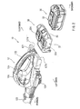
FIG. 1 is an overall perspective view of a blower (en electric machine) provided with a battery adapter according to an example of the present invention; -
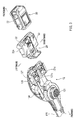
FIG. 2 is an exploded perspective view of the electric machine, viewed from above; -
FIG. 3 is an exploded perspective view of the electric machine, viewed from below; -
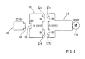
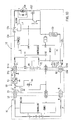
FIG. 4 is a diagram showing the configuration of the electric machine; -
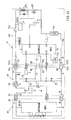
FIG. 5 is a schematic block diagram showing an electric circuit of the electric machine; -
FIG. 6 is a diagram showing the configuration of an electric machine provided with a battery adapter according to another example; -
FIG. 7 is a schematic block diagram showing an electric circuit of the electric machine; -
FIG. 8 is a schematic block diagram showing an electric circuit of the electric machine; -
FIG. 9 is a diagram showing the configuration of an electric machine provided with a battery adapter according to another example; -
FIG. 10 is a schematic block diagram showing an electric circuit of the electric machine; -
FIG. 11 is a diagram showing the configuration of an electric machine according to another example; -
FIG. 12 is a schematic block diagram showing an electric circuit of the electric machine; -
FIG. 13 is a schematic block diagram showing the electric circuit of the electric machine; and -
FIG. 14 is a side and a front view of a conventional electric tool provided with a pair of seats or sockets for respective battery packs. - Each of the additional features and teachings disclosed above and below may be utilized separately or in conjunction with other features and teachings to provide improved battery adapters. Representative examples of the present teaching, which examples utilize many of these additional features and teachings both separately and in conjunction with one another, will now be described in detail with reference to the attached drawings. This detailed description is merely intended to teach a person of skill in the art further details for practicing preferred aspects of the present teachings and is not intended to limit the scope of the invention. Only the claims define the scope of the claimed invention. Therefore, combinations of features and steps disclosed in the following detailed description may not be necessary to practice the invention in the broadest sense, and are instead taught merely to particularly describe representative examples of the invention. Moreover, various features of the representative examples and the dependent claims may be combined in ways that are not specifically enumerated in order to provide additional useful examples of the present teachings.
- In the following, a battery adapter according to an example will be described with reference to
FIG. 1 to FIG. 5 . The battery adapter according to the example is for use in electric machines, such as a blower. - The forward, backward, leftward, rightward, upward, and downward directions in the figures correspond to the forward, backward, leftward, rightward, upward, and downward directions in the blower.
- The
blower 10 is an equipment for blowing away dust, dirt, dust or the like. As shown inFIGS. 1 to 3 , theblower 10 includes a blowermain body 12, abattery adapter 20, and a battery pack 30 (hereinafter termed the battery 30). - Before describing the
battery adapter 20, the configuration of the blowermain body 12 will be briefly described. - The blower
main body 12 is configured such that air sucked in through a rotating fan (not shown) from anair intake port 121 provided in the central lower surface of the blowermain body 12 can be purged through anozzle 123 at a distal end (front end) of the blowermain body 12. At the central part of the blowermain body 12, ahousing part 124 for housing the fan and amotor 12m, etc. is provided above theair intake port 121. Agrip part 125 extends from above thehousing part 124 to the rear end position of the blowermain body 12. Amain switch 12s of the blowermain body 12 is provided at an upper position of thegrip part 125. Further, at the rear end position of the blowermain body 12, abattery connection part 127 is provided. - A
battery adapter 20, which is described below, or twoDC 18 volts batteries (not shown) may be connected to thebattery connection part 127. As shown inFIG. 3 , there are provided two sets of battery-connectingports battery connection part 127 to which thebattery adapter 20 or twoDC 18 volts batteries (not shown) can be connected (for example, through a sliding motion). - The blower
main body 12 shown inFIGS. 4 and5 can be driven by themotor 12m rated at 36 VDC. As shown inFIG. 5 , one end of apositive power line 12p of the blowermain body 12 is connected to a positive terminal P1 of the firstbattery connection port 127c, and the other end the of thepositive power line 12p is connected to a positive terminal p of themotor 12m. Afuse 12f and themain switch 12s are connected in series between the two ends of thepositive power line 12p. Further, one end of anegative power line 12n of the blowermain body 12 is connected to a negative terminal N2 of the secondbattery connection port 127d, and the other end of thenegative power line 12n is connected to a negative terminal n of themotor 12m. Between the two ends of thenegative power line 12n, a switching element FET, for adjusting the power supplied to themotor 12m, and ashunt resistor 12r, for detecting a load current of themotor 12m, are connected in series. - Further, as shown in
FIG. 5 , a negative terminal N1 of the firstbattery connection port 127c and a positive terminal P2 of the secondbattery connection port 127d are electrically connected to each other by ajumper line 12j. Therefore, whenDC 18 volts batteries (not shown) are respectively connected to the firstbattery connection port 127c and the secondbattery connection port 127d, the batteries are connected to each other in series, with the result that a voltage ofDC 36 volts is applied to themotor 12m. - Further, a controller MCU (refer to
FIG. 5 ) is mounted in thehousing part 124 of the blowermain body 12. The controller MCU is configured to operate the switching FET to control themotor 12m (refer to an IO3 terminal). When a discharge signal (discharge enabling signal) is input via AS terminals of the firstbattery connection port 127c and the secondbattery connection port 127d (refer to IO1 and IO2 terminals), the controller MCU operate to control themotor 12m. Further, the load current of themotor 12m is input to the controller MCU (refer to a terminal I4). When the controller MCU receives an overload current, the MCU stops themotor 12m, and also outputs an overload signal to the battery via the AS terminal. Further, the controller MCU can output a display signal to adisplay circuit 12w of the blowermain body 12. - The
battery adapter 20, which is provided with the firstbattery connection port 127c and the secondbattery connection port 127d, uses asingle battery 30 rated at 36VDC for driving the blowermain body 12 rated at 36 VDC . - As shown in
FIGS. 2 and3 , thebattery adapter 20 is provided with a thinboxlike housing 22. On an upper surface of thehousing 22, there is provided a first machine-side-connectingsection 22c and a second machine-side-connectingsection 22d which can be connected through sliding action to the firstbattery connection port 127c of the blowermain body 12 and the secondbattery connection port 127d of the blowermain body 12, respectively. Further, on the lower surface side of thehousing 22, there is provided a battery-side-connectingsection 23 to which aconnection part 33 of thebattery 30 rated at 36VDC can be connected via slide action. - As shown in
FIG. 5 , provided on the first machine-side-connectingsection 22c are a positive terminal P1, a negative terminal N1, and an AS1 terminal to which the positive terminal P1, the negative terminal N1, and an AS1 terminal of the firstbattery connection port 127c of the blowermain body 12 are respectively connected. Further, provided on the second machine-side-connectingsection 22d is a positive terminal P2, a negative terminal N2, and an AS2 terminal to which the positive terminal P2, the negative terminal N2, and an AS2 terminal of the secondbattery connection port 127d of the blowermain body 12 are respectively connected. - Further, on the battery-side-connecting
section 23 there is provided a positive terminal P, a negative terminal N, and an AS terminal to which a positive terminal P, a negative terminal N, and an AS terminal provided on theconnection part 33 of thebattery 30 are respectively connected. The positive terminal P of the battery-side-connectingsection 23 is connected to the positive terminal P1 of the first machine-side-connectingsection 22c, and the negative terminal N of the battery-side-connectingsection 23 is connected to the negative terminal N2 of the second machine-side-connectingsection 22d. Further, the AS terminal of the battery-side-connectingsection 23 is connected to the AS2 terminal of the second machine-side-connectingsection 22d. Accordingly, a signal from a controller BMU of thebattery 30, such as an over-discharge signal (discharge inhibit signal) etc., is input to the IO2 terminal of the controller MCU of the blowermain body 12 via the AS2 terminal of the second machine-side-connectingsection 22d of thebattery adapter 20. Further, an operation signal for themain switch 12s from the controller MCU of the blowermain body 12 is also transmitted to the controller BMU of thebattery 30 via the AS2 terminal of the second machine-side-connectingsection 22d. - In the
battery adapter 20, there is provided adischarge output circuit 24 that can output a discharge signal. The output signal is input to the IO1 terminal of the controller MCU of the blowermain body 12 via the AS1 terminal of the first machine-side-connectingsection 22c. The controller MCU of the blowermain body 12 controls themotor 12m according to an over-discharge signal (discharge inhibit signal) or a discharge signal (discharge enabling signal) input to the IO2 terminal. - Further, in the
battery adapter 20, there is provided a constant-voltage circuit 25 configured such that the same approximate voltage is applied between the positive terminal P1 and the negative terminal N1 of the first machine-side-connectingsection 22c and between the positive terminal P2 and the negative terminal N2 of the second machine-side-connectingsection 22d. - Next, an operation of the
battery adapter 20 will be described. - First, the
battery 30 is connected, preferably through slide movement, to the battery-side-connectingsection 23 of thebattery adapter 20, and then, the first machine-side-connectingsection 22c and the second machine-side-connectingsection 22d of thebattery adapter 20 are connected to the firstbattery connection port 127c and the secondbattery connection port 127d of the blowermain body 12 through sliding motion, as shown inFIG. 1 . As a result, as shown inFIG. 5 , the positive terminal P of thebattery 30 is connected to the positive terminal P1 of the firstbattery connection port 127c of the blowermain body 12 via the positive terminal P1 of the first machine-side-connectingsection 22c of thebattery adapter 20. Further, the negative terminal N of thebattery 30 is connected to the negative terminal N2 of the secondbattery connection port 127d of the blowermain body 12 via the negative terminal N2 of the second machine-side-connectingsection 22d of thebattery adapter 20. Further, the AS terminal of thebattery 30 is connected to the AS2 terminal of the secondbattery connection port 127d of the blowermain body 12 via the AS2 terminal of the second machine-side-connectingsection 22d of thebattery adapter 20. - As a result,
DC 18 volts is applied between the positive terminal P1 and the negative terminal N1 of the firstbattery connection port 127c and between the positive terminal P2 and the negative terminal N2 of the secondbattery connection port 127d of the blowermain body 12. That is, the voltage of the firstbattery connection port 127c (DC 18 volts) and the voltage of the secondbattery connection port 127d (DC 18 volts) are applied in series to themotor 12m of the blowermain body 12. As a result, it is possible to drive the blowermain body 12 rated at 36 VDC, which is provided with the firstbattery connection port 127c and the secondbattery connection port 127d, by use of asingle battery 30 rated at 36VDC. - In the
battery adapter 20 according to the example, it is possible to drive the blower main body 12 (electric machine) provided with a plurality of (two) battery-connectingports single battery 30. This can improve the usability of the blowermain body 12 provided with a plurality of (two) battery-connectingports - Further, the sum of the voltages applied to the machine-side-connecting
sections DC 18 volts) of thebattery adapter 20 is equal to the rated voltage (DC 36 volts) of themotor 12m of the blower main body 12 (electric machine). For this reason, the above-describedbattery adapter 20 makes it possible to drive a two-port blower main body 12 (electric machine) rated at 36VDC, which is provided with two battery-connectingports - In the following, a
battery adapter 40 according to another example will be described with reference toFIGS. 6 to 8 . - As shown in
FIG. 6 , thebattery adapter 40 according to the example can drive anelectric machine 12 rated at 18 VDC provided with a firstbattery connection port 127c and a secondbattery connection port 127d by use of asingle battery 30 rated at 36 VDC. The basic configuration of thebattery adapter 40 according to the example is the same as that of thebattery adapter 20 according to the first example. Therefore, the members that are the same as those of thebattery adapter 20 according to the first example are indicated by the same reference numerals, and an explanation of thebattery adapter 40 will be left out. - As shown in
FIG. 7 , theelectric machine 12 of this example is configured such that a battery rated at 18 VDC (not shown) can be connected in parallel to the firstbattery connection port 127c and the secondbattery connection port 127d. That is, in the aboveelectric machine 12, the parallel connection is made between the positive terminal P1 and the negative terminal N1 of the firstbattery connection port 127c and between the positive terminal P2 and the negative terminal N2 of the secondbattery connection port 127d. As a result, the approximately same voltage that is applied to the firstbattery connection port 127c and the secondbattery connection port 127d (DC 18 volts) will be applied to themotor 12m. - As is the case with the first example, the
battery adapter 40 is provided with a first machine-side-connectingsection 22c and a second machine-side-connectingsection 22d. However, as shown inFIG. 7 , the first machine-side-connectingsection 22c of thebattery adapter 40 does not include positive and negative terminals, and solely allows a mechanical connection with the firstbattery connection port 127c of theelectric machine 12. That is, only the second machine-side-connectingsection 22d of thebattery adapter 40 can be electrically connected to the secondbattery connection port 127d of theelectric machine 12. - The
battery adapter 40 is provided with a step-downsection 43 configured to reduce the voltage (DC 36 volts) applied to the positive terminal P and the negative terminal N of the battery-side-connectingsection 23. The step-downsection 43 is configured to reduceDC 36 volts toDC 18 volts. The output voltage (DC 18 volts) of the step-down section is applied between the positive terminal P2 and the negative terminal N2 of the second machine-side-connectingsection 22d. As a result, a voltage ofDC 18 volts is applied to the secondbattery connection port 127d of theelectric machine 12. - Further, the
battery adapter 40 is provided with an ASoutput circuit 45. The AS output circuit is configured to shut off the input power of the step-downsection 43 upon receiving an operation signal for themain switch 12s from the controller MCU of theelectric machine 12, or an over-discharge signal, etc., from the controller BMU of thebattery 30. - Therefore, the above-described
battery adapter 40 makes it possible to drive theelectric machine 12 provided with the firstbattery connection port 127c and the secondbattery connection port 127d by use of asingle battery 30 rated at 36VDC. In this way, it is possible to use thebattery 30 rated at 36VDC in order to drive theelectric machine 12 rated at 18VDC, and thus the electric machine may be advantageously operated for a longer period of time. - The above construction may not be limited by the above-described example and various changes may be made without departing from the scope of the invention. In
FIG. 7 , only the second machine-side-connectingsection 22d is used, without electrically using the first machine-side-connectingsection 22c of thebattery adapter 40. However, as shown inFIG. 8 , it is possible to applyDC 18 volts between the positive terminal P1 of the first machine-side-connectingsection 22c and the negative terminal N2 of the second machine-side-connectingsection 22d, for example. That is, it is possible to apply a voltage ofDC 18 volts to themotor 12m via the positive terminal P1 of the firstbattery connection port 127c and the negative terminal N2 of the secondbattery connection port 127d of theelectric machine 12. - In the following, a
battery adapter 50 according to another example will be described with reference toFIGS. 9 to 13 . - As shown in
FIG. 9 , thebattery adapter 50 according to the example can drive theelectric machine 12 rated at 36 VDC provided with the firstbattery connection port 127c and the secondbattery connection port 127d by use of asingle battery 60 rated at 18 VDC. The basic configuration of thebattery adapter 50 according to the example is the same as that of thebattery adapter 20 according to the first example. Therefore, the members that are the same as those of thebattery adapter 20 according to the first example are indicated by the same reference numerals, and a description of thebattery 50 will be left out. - Further, the
electric machine 12 in the example is the same as theelectric machine 12 in the first example. Therefore, the members of theelectric machine 12 are indicated by the same reference numerals, and a description of theelectric machine 12 will be left out. - As shown in
FIG. 10 , thebattery adapter 50 is provided with a step-upsection 53 configured to increase the voltage (DC 18 volts) applied to the positive terminal P and the negative terminal N of the battery-side-connectingsection 23. The step-upsection 53 is configured to increaseDC 18 volts toDC 36 volts. The output voltage (DC 36 volts) of the step-up section is applied between the positive terminal P1 of the first machine-side-connectingsection 22c and the negative terminal N2 of the second machine-side-connectingsection 22d. Further, on the output side of the step-upsection 53, there is provided a constant-voltage circuit 25 configured such that the same voltage (DC 18 volts) is applied between the positive terminal P1 and the negative terminal N1 of the first machine-side-connectingsection 22c and between the positive terminal P2 and the negative terminal N2 of the second machine-side-connectingsection 22d. - As a result, a voltage of
DC 18 volts is applied to the firstbattery connection port 127c and the secondbattery connection port 127d of theelectric machine 12 via the first machine-side-connectingsection 22c and the second machine-side-connectingsection 22d, respectively, of thebattery adapter 50. That is, a voltage ofDC 36 volts is applied to themotor 12m of theelectric machine 12. The voltage of the firstbattery connection port 127c (DC 18 volts) and the voltage of the secondbattery connection port 127d (DC 18 volts) are connected in series. - Accordingly, it is possible to drive the
electric machine 12 rated at 36VDC, which is provided with a firstbattery connection port 127c and a secondbattery connection port 127d, by use of asingle battery 60 rated at 18VDC. - The above construction may not be limited by the above-described example and various changes may be made without departing from the scope of the invention. In
FIG. 10 , a voltage ofDC 36 volts is applied to themotor 12m by connecting the firstbattery connection port 127c and the secondbattery connection port 127d of theelectric machine 12 in series. - However, as shown in
FIGS. 11 and12 , it is possible to apply a voltage ofDC 36 volts between the terminals P2 and N2 of the second machine-side-connectingsection 22d of thebattery adapter 50, without mounting the constant-voltage circuit 25. As a result, it is possible to use thebattery adapter 50 for theelectric machine 12 in which a battery rated at 36 VDC is connected to the firstbattery connection port 127c and the secondbattery connection port 127d in parallel, as shown inFIG. 12 . - Further, as shown in
FIG. 13 , it is also possible to apply a voltage ofDC 36 volts between the positive terminal P1 of the first machine-side-connectingsection 22c and the negative terminal N2 of the second machine-side-connectingsection 22d of thebattery adapter 50, without mounting the constant-voltage circuit 25. As a result, it is possible to use thebattery adapter 50 for theelectric machine 12 in which a battery rated at 36 VDC is connected to each of the firstbattery connection port 127c and the secondbattery connection port 127d in parallel, as shown inFIG. 13 . - In the first example to the third example, the
battery adapter sections section 23. However, it is also possible to change the number of machine-side-connecting sections and the number of battery-side-connecting sections as appropriate but preferably such that the number of machine-side-connecting sections is larger than the number of battery-side-connecting sections. - Further, in the first through the third examples, the
blower 10 is shown as an example of theelectric machine 12. However, a chain saw, a hedge trimmer, and other electric tools such as those for a drill or an electric screwdriver that use an external battery or batteries can also be used with the invention. - It is explicitly stated that all features disclosed in the description and/or the claims are intended to be disclosed separately and independently from each other for the purpose of original disclosure as well as for the purpose of restricting the claimed invention independent of the composition of the features in the embodiments and/or the claims. It is explicitly stated that all value ranges or indications of groups of entities disclose every possible intermediate value or intermediate entity for the purpose of original disclosure as well as for the purpose of restricting the claimed invention, in particular as limits of value ranges.
Claims (14)
- A battery adapter (20; 40; 50), comprising a plurality of machine-side-connecting sections (22c, 22d) that can be connected to a plurality of battery-connecting ports (127c, 127d) provided on an electric machine (12) and also comprising a battery-side-connecting section (23) that can be connected to a battery (30; 60),
wherein the electric machine (12) connected to the machine-side-connecting sections (22c, 22d) of the battery adapter (20; 40; 50) via the battery-connecting ports (127c, 127d) of the electric machine (12) can be driven by the battery (30; 60) connected to the battery-side-connecting section (23) of the battery adapter (20; 40; 50). - The battery adapter (20; 40; 50) according to claim 1, wherein there are a plurality of battery-side-connecting sections (23) and further that the number of the machine-side-connecting sections (22c, 22d) is configured to be larger than the number of the battery-side-connecting sections (23).
- The battery adapter (20; 40; 50) according to claim 1 or 2, wherein the electric machine (12) connected to the machine-side-connecting sections (22c, 22d) of the battery adapter (20; 40; 50) via the battery-connecting ports (127c, 127d) of the electric machine (12) can be driven by a battery the nominal voltage of which is substantially equal to the rated voltage of a motor of the electric machine (12), the battery (30; 60) being connected to the battery-side-connecting section (23) of the battery adapter (20; 40; 50).
- The battery adapter (20; 40; 50) according to one of claims 1 to 3, wherein the sum of the voltages applied to the machine-side-connecting sections (22c, 22d) of the battery adapter (20; 40; 50) is equal to the rated voltage of the motor of the electric machine (12).
- The battery adapter (20; 40; 50) according to claim 1, wherein the battery adapter (20; 40; 50) includes a step-down section (43) that is configured to reduce the battery voltage applied to the battery-side-connecting section (23); and
the output voltage of the step-down section (43) is configured to be equal to the rated voltage of the motor of the electric machine (12). - The battery adapter (20; 40; 50) according to claim 2, wherein the battery adapter (20; 40; 50) includes a step-down section (43) that is configured to reduce the battery voltage applied to the battery-side-connecting sections (23); and
the output voltage of the step-down section (43) is configured to be equal to the rated voltage of the motor of the electric machine (12). - The battery adapter (20; 40; 50) according to claim 5 or 6, wherein the output voltage of the step-down section (43) is equal to the voltage applied to one of the machine-side-connecting sections (22c, 22d).
- The battery adapter (20; 40; 50) according to claim 5, 6 or 7, wherein the output voltage of the step-down section (43) is applied between positive and negative terminals of different sets of the plurality of machine-side-connecting sections (22c, 22d).
- The battery adapter (20; 40; 50) according to claim 1, wherein the battery (30; 60) includes a step-up section (53) configured to increase the battery voltage applied to the battery-side-connecting section (23); and
the output voltage of the step-up section (53) is configured to be equal to the rated voltage of the motor of the electric machine (12). - The battery adapter (20; 40; 50) according to claim 2, wherein the battery adapter (20; 40; 50) includes a step-up section (53) configured to increase the battery voltage applied to the battery-side-connecting sections (23); and
the output voltage of the step-up section (53) is configured to be equal to the rated voltage of the motor of the electric machine (12). - The battery adapter (20; 40; 50) according to claim 9 or 10, wherein the output voltage of the step-up section (53) is configured to be equal to the sum of the voltages applied to the machine-side-connecting sections (22c, 22d).
- The battery adapter (20; 40; 50) according to claim 9 or 10, wherein the output voltage of the step-up section (53) is equal to the voltage applied to one of the machine-side-connecting sections (22c, 22d).
- The battery adapter (20; 40; 50) according to any one of claims 9 to 12, wherein the output voltage of the step-up section (53) is applied between positive and negative terminals of different sets of the plurality of machine-side-connecting sections (22c, 22d).
- A battery adapter (20; 40; 50) for use with an electric machine (12), comprising:a battery-side-connection section (23) configured to receive a battery voltage from one or more batteries (30; 60); anda plurality of machine-side-connecting sections (22c, 22d) configured to transmit an output voltage from the battery adapter (20; 40; 50) to the electric machine (12),wherein the number of machine-side-connections is greater than the number of battery-side-connections; andwherein the battery adapter (20; 40; 50) has a step function (43; 53) configured to adjust the battery voltage such that the output voltage from the machine-side-connecting sections (22c, 22d) is sufficient to power the electric machine (12).
Applications Claiming Priority (1)
| Application Number | Priority Date | Filing Date | Title |
|---|---|---|---|
| JP2011252650A JP5758276B2 (en) | 2011-11-18 | 2011-11-18 | Battery adapter |
Publications (3)
| Publication Number | Publication Date |
|---|---|
| EP2595273A2 true EP2595273A2 (en) | 2013-05-22 |
| EP2595273A3 EP2595273A3 (en) | 2014-06-04 |
| EP2595273B1 EP2595273B1 (en) | 2018-01-03 |
Family
ID=47294676
Family Applications (1)
| Application Number | Title | Priority Date | Filing Date |
|---|---|---|---|
| EP12193032.5A Active EP2595273B1 (en) | 2011-11-18 | 2012-11-16 | Battery adapter |
Country Status (5)
| Country | Link |
|---|---|
| US (1) | US9160125B2 (en) |
| EP (1) | EP2595273B1 (en) |
| JP (1) | JP5758276B2 (en) |
| CN (1) | CN103124089B (en) |
| RU (1) | RU2012148890A (en) |
Cited By (2)
| Publication number | Priority date | Publication date | Assignee | Title |
|---|---|---|---|---|
| FR3044480A1 (en) * | 2015-11-30 | 2017-06-02 | Voung Vui Mu | UNIVERSAL BATTERY SUPPORT FOR ELECTROPORTATIVE TOOLS |
| DE102018102060A1 (en) | 2018-01-30 | 2019-08-01 | Metabowerke Gmbh | Electric appliance and battery charger |
Families Citing this family (28)
| Publication number | Priority date | Publication date | Assignee | Title |
|---|---|---|---|---|
| JP2657593B2 (en) | 1991-12-14 | 1997-09-24 | ブリヂストンサイクル株式会社 | Method and apparatus for cutting woven fabric such as tatami mats |
| WO2010092885A1 (en) * | 2009-02-10 | 2010-08-19 | 株式会社マキタ | Motor-driven tool |
| JP6032400B2 (en) * | 2012-08-15 | 2016-11-30 | 日立工機株式会社 | Chainsaw |
| JP6104717B2 (en) * | 2013-05-31 | 2017-03-29 | 株式会社マキタ | Adapter unit, electric work machine set |
| CN108400629B (en) * | 2014-05-18 | 2023-01-24 | 百得有限公司 | Battery |
| EP3025825A1 (en) * | 2014-11-27 | 2016-06-01 | HILTI Aktiengesellschaft | Self-locking latch of an adapter device |
| EP3035484A1 (en) * | 2014-12-18 | 2016-06-22 | HILTI Aktiengesellschaft | Switchable interface for machine tools |
| JP6673347B2 (en) * | 2015-05-29 | 2020-03-25 | 工機ホールディングス株式会社 | Electric work machine |
| US9877435B2 (en) * | 2015-09-15 | 2018-01-30 | Chervon (Hk) Limited | Hedge trimmer |
| CN106654131A (en) * | 2016-11-16 | 2017-05-10 | 南京久驰机电实业有限公司 | Electric tool system |
| USD907576S1 (en) * | 2017-06-06 | 2021-01-12 | Black & Decker Inc. | Electric connector |
| CN109860443A (en) * | 2017-11-30 | 2019-06-07 | 南京德朔实业有限公司 | A kind of battery pack assembly |
| JP7068959B2 (en) * | 2018-08-02 | 2022-05-17 | 株式会社クボタ | Battery connector assembly and battery equipment |
| WO2020066904A1 (en) * | 2018-09-28 | 2020-04-02 | 工機ホールディングス株式会社 | Adapter and electrical device system |
| JP7118862B2 (en) * | 2018-10-30 | 2022-08-16 | 株式会社マキタ | Cutting machine |
| JP7159042B2 (en) * | 2018-12-27 | 2022-10-24 | 株式会社マキタ | battery system |
| JP7110129B2 (en) * | 2019-01-22 | 2022-08-01 | 株式会社マキタ | Power control device, power supply device and electric work system |
| DE102019218584A1 (en) * | 2019-11-29 | 2021-06-02 | Robert Bosch Gmbh | Battery operated device with a battery interface |
| CN110829556B (en) * | 2019-12-12 | 2026-03-27 | 格力博(江苏)股份有限公司 | An adapter and a power tool system |
| WO2021254426A1 (en) * | 2020-06-18 | 2021-12-23 | Globe (jiangsu) Co., Ltd. | Power tool and power tool system |
| DE102020117507A1 (en) | 2020-07-02 | 2022-01-05 | Metabowerke Gmbh | System for charging battery packs |
| CN116686148B (en) * | 2021-02-12 | 2025-08-01 | 工机控股株式会社 | Adapter, electric machine, and electric machine body |
| JP7585878B2 (en) * | 2021-02-26 | 2024-11-19 | 工機ホールディングス株式会社 | Electrical Equipment |
| EP4190498A1 (en) * | 2021-12-01 | 2023-06-07 | Hilti Aktiengesellschaft | Power supply device and systems comprising machine tools and power supply devices |
| USD1024969S1 (en) * | 2022-01-21 | 2024-04-30 | Ningbo Myling Electric Co., ltd | Electrical extension cord |
| USD1021770S1 (en) * | 2022-03-03 | 2024-04-09 | Vincent G. McIntosh | Power tool battery converter |
| WO2025115475A1 (en) * | 2023-11-28 | 2025-06-05 | 工機ホールディングス株式会社 | Battery pack and electric apparatus |
| WO2025169828A1 (en) * | 2024-02-09 | 2025-08-14 | 工機ホールディングス株式会社 | Adapter system, first adapter system, second adapter system, and third adapter system |
Citations (2)
| Publication number | Priority date | Publication date | Assignee | Title |
|---|---|---|---|---|
| US5028858A (en) | 1988-12-23 | 1991-07-02 | Metabowerke Gmbh & Co. | Cordless dual-battery electric tool |
| JP2011252650A (en) | 2010-06-01 | 2011-12-15 | Daio Paper Corp | Rotary kiln, and method for producing recycled particles |
Family Cites Families (20)
| Publication number | Priority date | Publication date | Assignee | Title |
|---|---|---|---|---|
| JPH02120751U (en) * | 1989-03-16 | 1990-09-28 | ||
| US5418403A (en) * | 1992-11-05 | 1995-05-23 | The United States Of America As Represented By The Secretary Of The Navy | System for conveniently providing load testing termination of an AC power source having at least one battery |
| US5929597A (en) * | 1997-04-23 | 1999-07-27 | Fiskars Inc. | Portable electrical power system to supply direct current voltage |
| US6007373A (en) * | 1998-05-22 | 1999-12-28 | Chew; William E. | Apparatuses and methods for coupling DC power tools to external DC power sources |
| US6166519A (en) * | 2000-01-20 | 2000-12-26 | Gault; Bibb T. | Camera battery adapter system |
| US6806683B2 (en) * | 2002-02-05 | 2004-10-19 | Litton Systems, Inc. | Battery adapter for night vision device |
| US6844705B2 (en) * | 2002-12-09 | 2005-01-18 | Intersil Americas Inc. | Li-ion/Li-polymer battery charger configured to be DC-powered from multiple types of wall adapters |
| US6982532B2 (en) * | 2003-12-08 | 2006-01-03 | A. O. Smith Corporation | Electric machine |
| US7176656B2 (en) * | 2004-06-22 | 2007-02-13 | Campbell Hausfeld/Scott Fetzer Company | Tool with battery pack |
| US20070210744A1 (en) * | 2006-03-10 | 2007-09-13 | Watson James B | Adapter for a power tool battery |
| JP4993404B2 (en) * | 2006-06-21 | 2012-08-08 | 日立工機株式会社 | Portable power tools |
| JP4968624B2 (en) * | 2006-09-19 | 2012-07-04 | 日立工機株式会社 | Adapter, combination of battery pack and adapter, and electric tool equipped with them |
| JP5574138B2 (en) * | 2006-09-19 | 2014-08-20 | 日立工機株式会社 | Adapter, combination of battery pack and adapter, and electric tool equipped with them |
| US7576515B2 (en) * | 2007-04-03 | 2009-08-18 | Knight's Armament Co. | Battery adapter system and night-vision scope using same |
| DE102008040061A1 (en) * | 2008-07-02 | 2010-01-07 | Robert Bosch Gmbh | Power tool |
| JP5432761B2 (en) * | 2010-02-12 | 2014-03-05 | 株式会社マキタ | Electric tool powered by multiple battery packs |
| JP5461221B2 (en) * | 2010-02-12 | 2014-04-02 | 株式会社マキタ | Electric tool powered by multiple battery packs |
| JP5616104B2 (en) * | 2010-04-12 | 2014-10-29 | 株式会社マキタ | Power tools powered by battery packs and their adapters |
| CN201781300U (en) * | 2010-08-13 | 2011-03-30 | 北京航天光华电子技术有限公司 | Portable multifunctional power supply with lithium battery |
| US20120139345A1 (en) * | 2010-12-01 | 2012-06-07 | Texas Instruments Incorporated | Control method of hybrid power battery charger |
-
2011
- 2011-11-18 JP JP2011252650A patent/JP5758276B2/en active Active
-
2012
- 2012-09-17 CN CN201210345390.7A patent/CN103124089B/en active Active
- 2012-11-14 US US13/676,688 patent/US9160125B2/en active Active
- 2012-11-16 RU RU2012148890/07A patent/RU2012148890A/en unknown
- 2012-11-16 EP EP12193032.5A patent/EP2595273B1/en active Active
Patent Citations (2)
| Publication number | Priority date | Publication date | Assignee | Title |
|---|---|---|---|---|
| US5028858A (en) | 1988-12-23 | 1991-07-02 | Metabowerke Gmbh & Co. | Cordless dual-battery electric tool |
| JP2011252650A (en) | 2010-06-01 | 2011-12-15 | Daio Paper Corp | Rotary kiln, and method for producing recycled particles |
Cited By (5)
| Publication number | Priority date | Publication date | Assignee | Title |
|---|---|---|---|---|
| FR3044480A1 (en) * | 2015-11-30 | 2017-06-02 | Voung Vui Mu | UNIVERSAL BATTERY SUPPORT FOR ELECTROPORTATIVE TOOLS |
| WO2017093177A1 (en) * | 2015-11-30 | 2017-06-08 | Mu Voung Vui | Universal battery mount for portable electric power tool |
| CN108472804A (en) * | 2015-11-30 | 2018-08-31 | 木冯维 | Universal battery holder for portable power tools |
| CN108472804B (en) * | 2015-11-30 | 2022-05-06 | 巫文伟 | Universal battery holder for portable power tools |
| DE102018102060A1 (en) | 2018-01-30 | 2019-08-01 | Metabowerke Gmbh | Electric appliance and battery charger |
Also Published As
| Publication number | Publication date |
|---|---|
| RU2012148890A (en) | 2014-05-27 |
| JP5758276B2 (en) | 2015-08-05 |
| US20130130552A1 (en) | 2013-05-23 |
| EP2595273A3 (en) | 2014-06-04 |
| JP2013109894A (en) | 2013-06-06 |
| CN103124089B (en) | 2016-01-06 |
| CN103124089A (en) | 2013-05-29 |
| EP2595273B1 (en) | 2018-01-03 |
| US9160125B2 (en) | 2015-10-13 |
Similar Documents
| Publication | Publication Date | Title |
|---|---|---|
| EP2595273B1 (en) | Battery adapter | |
| US10587134B2 (en) | Battery pack | |
| JP6962370B2 (en) | Battery packs and electrical equipment using battery packs | |
| US10348110B2 (en) | Battery pack | |
| JP5525358B2 (en) | Power tool powered by battery pack and its adapter | |
| JP5461221B2 (en) | Electric tool powered by multiple battery packs | |
| CN106232301B (en) | Improvements in Portable Power | |
| JP5593200B2 (en) | Electric tool system | |
| US8604724B2 (en) | Variable speed switch | |
| EP1903657A3 (en) | Adaptor, assembly of battery pack and adaptor, and electric tool with the same | |
| JP2011161603A (en) | Power tool using a plurality of battery packs as power source | |
| EP2696466A2 (en) | Adapter and electric power tool | |
| JP5395771B2 (en) | Electric tool | |
| JP2012110202A (en) | Electric tool system | |
| CN101689763A (en) | Battery protection ic and battery device | |
| EP1465316A2 (en) | Rechargeable battery devices | |
| CN213184487U (en) | Battery | |
| JP2014091176A (en) | Electric power tool | |
| JP2012200107A (en) | Charge battery pack | |
| WO2023054447A1 (en) | Battery pack and electric device | |
| JP6619069B2 (en) | Adapter for connecting multiple battery packs to the power tool body | |
| US20240014671A1 (en) | Battery-powered system, battery pack, electric work machine, and charger | |
| JP2014100785A (en) | Power tool using plural battery packs as power source | |
| CN116367965A (en) | Battery-operated hand-held power tools, battery unit for hand-held power tools, system with hand-held power tool and battery unit, charging device for battery unit and system with battery unit and charging device | |
| JP6073426B2 (en) | Electric tool powered by multiple battery packs |
Legal Events
| Date | Code | Title | Description |
|---|---|---|---|
| PUAI | Public reference made under article 153(3) epc to a published international application that has entered the european phase |
Free format text: ORIGINAL CODE: 0009012 |
|
| AK | Designated contracting states |
Kind code of ref document: A2 Designated state(s): AL AT BE BG CH CY CZ DE DK EE ES FI FR GB GR HR HU IE IS IT LI LT LU LV MC MK MT NL NO PL PT RO RS SE SI SK SM TR |
|
| AX | Request for extension of the european patent |
Extension state: BA ME |
|
| PUAL | Search report despatched |
Free format text: ORIGINAL CODE: 0009013 |
|
| AK | Designated contracting states |
Kind code of ref document: A3 Designated state(s): AL AT BE BG CH CY CZ DE DK EE ES FI FR GB GR HR HU IE IS IT LI LT LU LV MC MK MT NL NO PL PT RO RS SE SI SK SM TR |
|
| AX | Request for extension of the european patent |
Extension state: BA ME |
|
| RIC1 | Information provided on ipc code assigned before grant |
Ipc: H02J 7/00 20060101AFI20140429BHEP Ipc: H01M 2/10 20060101ALI20140429BHEP |
|
| 17P | Request for examination filed |
Effective date: 20141118 |
|
| RBV | Designated contracting states (corrected) |
Designated state(s): AL AT BE BG CH CY CZ DE DK EE ES FI FR GB GR HR HU IE IS IT LI LT LU LV MC MK MT NL NO PL PT RO RS SE SI SK SM TR |
|
| GRAP | Despatch of communication of intention to grant a patent |
Free format text: ORIGINAL CODE: EPIDOSNIGR1 |
|
| INTG | Intention to grant announced |
Effective date: 20170629 |
|
| GRAS | Grant fee paid |
Free format text: ORIGINAL CODE: EPIDOSNIGR3 |
|
| GRAA | (expected) grant |
Free format text: ORIGINAL CODE: 0009210 |
|
| AK | Designated contracting states |
Kind code of ref document: B1 Designated state(s): AL AT BE BG CH CY CZ DE DK EE ES FI FR GB GR HR HU IE IS IT LI LT LU LV MC MK MT NL NO PL PT RO RS SE SI SK SM TR |
|
| REG | Reference to a national code |
Ref country code: GB Ref legal event code: FG4D |
|
| REG | Reference to a national code |
Ref country code: CH Ref legal event code: EP Ref country code: AT Ref legal event code: REF Ref document number: 961104 Country of ref document: AT Kind code of ref document: T Effective date: 20180115 |
|
| REG | Reference to a national code |
Ref country code: IE Ref legal event code: FG4D |
|
| REG | Reference to a national code |
Ref country code: DE Ref legal event code: R096 Ref document number: 602012041546 Country of ref document: DE |
|
| REG | Reference to a national code |
Ref country code: NL Ref legal event code: MP Effective date: 20180103 |
|
| REG | Reference to a national code |
Ref country code: LT Ref legal event code: MG4D |
|
| REG | Reference to a national code |
Ref country code: AT Ref legal event code: MK05 Ref document number: 961104 Country of ref document: AT Kind code of ref document: T Effective date: 20180103 |
|
| PG25 | Lapsed in a contracting state [announced via postgrant information from national office to epo] |
Ref country code: NL Free format text: LAPSE BECAUSE OF FAILURE TO SUBMIT A TRANSLATION OF THE DESCRIPTION OR TO PAY THE FEE WITHIN THE PRESCRIBED TIME-LIMIT Effective date: 20180103 |
|
| PG25 | Lapsed in a contracting state [announced via postgrant information from national office to epo] |
Ref country code: FI Free format text: LAPSE BECAUSE OF FAILURE TO SUBMIT A TRANSLATION OF THE DESCRIPTION OR TO PAY THE FEE WITHIN THE PRESCRIBED TIME-LIMIT Effective date: 20180103 Ref country code: HR Free format text: LAPSE BECAUSE OF FAILURE TO SUBMIT A TRANSLATION OF THE DESCRIPTION OR TO PAY THE FEE WITHIN THE PRESCRIBED TIME-LIMIT Effective date: 20180103 Ref country code: LT Free format text: LAPSE BECAUSE OF FAILURE TO SUBMIT A TRANSLATION OF THE DESCRIPTION OR TO PAY THE FEE WITHIN THE PRESCRIBED TIME-LIMIT Effective date: 20180103 Ref country code: CY Free format text: LAPSE BECAUSE OF FAILURE TO SUBMIT A TRANSLATION OF THE DESCRIPTION OR TO PAY THE FEE WITHIN THE PRESCRIBED TIME-LIMIT Effective date: 20180103 Ref country code: NO Free format text: LAPSE BECAUSE OF FAILURE TO SUBMIT A TRANSLATION OF THE DESCRIPTION OR TO PAY THE FEE WITHIN THE PRESCRIBED TIME-LIMIT Effective date: 20180403 Ref country code: ES Free format text: LAPSE BECAUSE OF FAILURE TO SUBMIT A TRANSLATION OF THE DESCRIPTION OR TO PAY THE FEE WITHIN THE PRESCRIBED TIME-LIMIT Effective date: 20180103 |
|
| PG25 | Lapsed in a contracting state [announced via postgrant information from national office to epo] |
Ref country code: IS Free format text: LAPSE BECAUSE OF FAILURE TO SUBMIT A TRANSLATION OF THE DESCRIPTION OR TO PAY THE FEE WITHIN THE PRESCRIBED TIME-LIMIT Effective date: 20180503 Ref country code: BG Free format text: LAPSE BECAUSE OF FAILURE TO SUBMIT A TRANSLATION OF THE DESCRIPTION OR TO PAY THE FEE WITHIN THE PRESCRIBED TIME-LIMIT Effective date: 20180403 Ref country code: AT Free format text: LAPSE BECAUSE OF FAILURE TO SUBMIT A TRANSLATION OF THE DESCRIPTION OR TO PAY THE FEE WITHIN THE PRESCRIBED TIME-LIMIT Effective date: 20180103 Ref country code: SE Free format text: LAPSE BECAUSE OF FAILURE TO SUBMIT A TRANSLATION OF THE DESCRIPTION OR TO PAY THE FEE WITHIN THE PRESCRIBED TIME-LIMIT Effective date: 20180103 Ref country code: LV Free format text: LAPSE BECAUSE OF FAILURE TO SUBMIT A TRANSLATION OF THE DESCRIPTION OR TO PAY THE FEE WITHIN THE PRESCRIBED TIME-LIMIT Effective date: 20180103 Ref country code: RS Free format text: LAPSE BECAUSE OF FAILURE TO SUBMIT A TRANSLATION OF THE DESCRIPTION OR TO PAY THE FEE WITHIN THE PRESCRIBED TIME-LIMIT Effective date: 20180103 Ref country code: GR Free format text: LAPSE BECAUSE OF FAILURE TO SUBMIT A TRANSLATION OF THE DESCRIPTION OR TO PAY THE FEE WITHIN THE PRESCRIBED TIME-LIMIT Effective date: 20180404 Ref country code: PL Free format text: LAPSE BECAUSE OF FAILURE TO SUBMIT A TRANSLATION OF THE DESCRIPTION OR TO PAY THE FEE WITHIN THE PRESCRIBED TIME-LIMIT Effective date: 20180103 |
|
| REG | Reference to a national code |
Ref country code: DE Ref legal event code: R097 Ref document number: 602012041546 Country of ref document: DE |
|
| PG25 | Lapsed in a contracting state [announced via postgrant information from national office to epo] |
Ref country code: EE Free format text: LAPSE BECAUSE OF FAILURE TO SUBMIT A TRANSLATION OF THE DESCRIPTION OR TO PAY THE FEE WITHIN THE PRESCRIBED TIME-LIMIT Effective date: 20180103 Ref country code: RO Free format text: LAPSE BECAUSE OF FAILURE TO SUBMIT A TRANSLATION OF THE DESCRIPTION OR TO PAY THE FEE WITHIN THE PRESCRIBED TIME-LIMIT Effective date: 20180103 Ref country code: AL Free format text: LAPSE BECAUSE OF FAILURE TO SUBMIT A TRANSLATION OF THE DESCRIPTION OR TO PAY THE FEE WITHIN THE PRESCRIBED TIME-LIMIT Effective date: 20180103 Ref country code: IT Free format text: LAPSE BECAUSE OF FAILURE TO SUBMIT A TRANSLATION OF THE DESCRIPTION OR TO PAY THE FEE WITHIN THE PRESCRIBED TIME-LIMIT Effective date: 20180103 |
|
| PLBE | No opposition filed within time limit |
Free format text: ORIGINAL CODE: 0009261 |
|
| STAA | Information on the status of an ep patent application or granted ep patent |
Free format text: STATUS: NO OPPOSITION FILED WITHIN TIME LIMIT |
|
| PG25 | Lapsed in a contracting state [announced via postgrant information from national office to epo] |
Ref country code: DK Free format text: LAPSE BECAUSE OF FAILURE TO SUBMIT A TRANSLATION OF THE DESCRIPTION OR TO PAY THE FEE WITHIN THE PRESCRIBED TIME-LIMIT Effective date: 20180103 Ref country code: SK Free format text: LAPSE BECAUSE OF FAILURE TO SUBMIT A TRANSLATION OF THE DESCRIPTION OR TO PAY THE FEE WITHIN THE PRESCRIBED TIME-LIMIT Effective date: 20180103 Ref country code: SM Free format text: LAPSE BECAUSE OF FAILURE TO SUBMIT A TRANSLATION OF THE DESCRIPTION OR TO PAY THE FEE WITHIN THE PRESCRIBED TIME-LIMIT Effective date: 20180103 Ref country code: CZ Free format text: LAPSE BECAUSE OF FAILURE TO SUBMIT A TRANSLATION OF THE DESCRIPTION OR TO PAY THE FEE WITHIN THE PRESCRIBED TIME-LIMIT Effective date: 20180103 |
|
| 26N | No opposition filed |
Effective date: 20181005 |
|
| PG25 | Lapsed in a contracting state [announced via postgrant information from national office to epo] |
Ref country code: SI Free format text: LAPSE BECAUSE OF FAILURE TO SUBMIT A TRANSLATION OF THE DESCRIPTION OR TO PAY THE FEE WITHIN THE PRESCRIBED TIME-LIMIT Effective date: 20180103 |
|
| REG | Reference to a national code |
Ref country code: CH Ref legal event code: PL |
|
| GBPC | Gb: european patent ceased through non-payment of renewal fee |
Effective date: 20181116 |
|
| PG25 | Lapsed in a contracting state [announced via postgrant information from national office to epo] |
Ref country code: LU Free format text: LAPSE BECAUSE OF NON-PAYMENT OF DUE FEES Effective date: 20181116 Ref country code: MC Free format text: LAPSE BECAUSE OF FAILURE TO SUBMIT A TRANSLATION OF THE DESCRIPTION OR TO PAY THE FEE WITHIN THE PRESCRIBED TIME-LIMIT Effective date: 20180103 |
|
| REG | Reference to a national code |
Ref country code: BE Ref legal event code: MM Effective date: 20181130 |
|
| REG | Reference to a national code |
Ref country code: IE Ref legal event code: MM4A |
|
| PG25 | Lapsed in a contracting state [announced via postgrant information from national office to epo] |
Ref country code: LI Free format text: LAPSE BECAUSE OF NON-PAYMENT OF DUE FEES Effective date: 20181130 Ref country code: CH Free format text: LAPSE BECAUSE OF NON-PAYMENT OF DUE FEES Effective date: 20181130 |
|
| PG25 | Lapsed in a contracting state [announced via postgrant information from national office to epo] |
Ref country code: IE Free format text: LAPSE BECAUSE OF NON-PAYMENT OF DUE FEES Effective date: 20181116 Ref country code: FR Free format text: LAPSE BECAUSE OF NON-PAYMENT OF DUE FEES Effective date: 20181130 |
|
| PG25 | Lapsed in a contracting state [announced via postgrant information from national office to epo] |
Ref country code: BE Free format text: LAPSE BECAUSE OF NON-PAYMENT OF DUE FEES Effective date: 20181130 |
|
| PG25 | Lapsed in a contracting state [announced via postgrant information from national office to epo] |
Ref country code: GB Free format text: LAPSE BECAUSE OF NON-PAYMENT OF DUE FEES Effective date: 20181116 |
|
| PG25 | Lapsed in a contracting state [announced via postgrant information from national office to epo] |
Ref country code: MT Free format text: LAPSE BECAUSE OF NON-PAYMENT OF DUE FEES Effective date: 20181116 |
|
| PG25 | Lapsed in a contracting state [announced via postgrant information from national office to epo] |
Ref country code: TR Free format text: LAPSE BECAUSE OF FAILURE TO SUBMIT A TRANSLATION OF THE DESCRIPTION OR TO PAY THE FEE WITHIN THE PRESCRIBED TIME-LIMIT Effective date: 20180103 |
|
| PG25 | Lapsed in a contracting state [announced via postgrant information from national office to epo] |
Ref country code: PT Free format text: LAPSE BECAUSE OF FAILURE TO SUBMIT A TRANSLATION OF THE DESCRIPTION OR TO PAY THE FEE WITHIN THE PRESCRIBED TIME-LIMIT Effective date: 20180103 |
|
| PG25 | Lapsed in a contracting state [announced via postgrant information from national office to epo] |
Ref country code: HU Free format text: LAPSE BECAUSE OF FAILURE TO SUBMIT A TRANSLATION OF THE DESCRIPTION OR TO PAY THE FEE WITHIN THE PRESCRIBED TIME-LIMIT; INVALID AB INITIO Effective date: 20121116 Ref country code: MK Free format text: LAPSE BECAUSE OF NON-PAYMENT OF DUE FEES Effective date: 20180103 |
|
| PGFP | Annual fee paid to national office [announced via postgrant information from national office to epo] |
Ref country code: DE Payment date: 20250930 Year of fee payment: 14 |