EP2595254A2 - Fluidproof connector and assembling method therefor - Google Patents
Fluidproof connector and assembling method therefor Download PDFInfo
- Publication number
- EP2595254A2 EP2595254A2 EP12006462.1A EP12006462A EP2595254A2 EP 2595254 A2 EP2595254 A2 EP 2595254A2 EP 12006462 A EP12006462 A EP 12006462A EP 2595254 A2 EP2595254 A2 EP 2595254A2
- Authority
- EP
- European Patent Office
- Prior art keywords
- housing
- wall
- locking
- head portion
- protection wall
- Prior art date
- Legal status (The legal status is an assumption and is not a legal conclusion. Google has not performed a legal analysis and makes no representation as to the accuracy of the status listed.)
- Withdrawn
Links
- 238000000034 method Methods 0.000 title claims description 5
- 230000013011 mating Effects 0.000 claims abstract description 34
- 230000000149 penetrating effect Effects 0.000 claims abstract description 9
- 230000002093 peripheral effect Effects 0.000 claims description 27
- 230000003014 reinforcing effect Effects 0.000 claims description 13
- XLYOFNOQVPJJNP-UHFFFAOYSA-N water Substances O XLYOFNOQVPJJNP-UHFFFAOYSA-N 0.000 description 6
- 238000007689 inspection Methods 0.000 description 5
- 238000007789 sealing Methods 0.000 description 5
- 229920003002 synthetic resin Polymers 0.000 description 3
- 239000000057 synthetic resin Substances 0.000 description 3
- 239000012530 fluid Substances 0.000 description 2
- 238000012790 confirmation Methods 0.000 description 1
- 230000001419 dependent effect Effects 0.000 description 1
- 238000006073 displacement reaction Methods 0.000 description 1
- 230000000694 effects Effects 0.000 description 1
- 238000003780 insertion Methods 0.000 description 1
- 230000037431 insertion Effects 0.000 description 1
- 238000012423 maintenance Methods 0.000 description 1
- 239000012858 resilient material Substances 0.000 description 1
- 238000000926 separation method Methods 0.000 description 1
- 230000000007 visual effect Effects 0.000 description 1
Images



Classifications
-
- H—ELECTRICITY
- H01—ELECTRIC ELEMENTS
- H01R—ELECTRICALLY-CONDUCTIVE CONNECTIONS; STRUCTURAL ASSOCIATIONS OF A PLURALITY OF MUTUALLY-INSULATED ELECTRICAL CONNECTING ELEMENTS; COUPLING DEVICES; CURRENT COLLECTORS
- H01R13/00—Details of coupling devices of the kinds covered by groups H01R12/70 or H01R24/00 - H01R33/00
- H01R13/46—Bases; Cases
- H01R13/52—Dustproof, splashproof, drip-proof, waterproof, or flameproof cases
- H01R13/5219—Sealing means between coupling parts, e.g. interfacial seal
-
- H—ELECTRICITY
- H01—ELECTRIC ELEMENTS
- H01R—ELECTRICALLY-CONDUCTIVE CONNECTIONS; STRUCTURAL ASSOCIATIONS OF A PLURALITY OF MUTUALLY-INSULATED ELECTRICAL CONNECTING ELEMENTS; COUPLING DEVICES; CURRENT COLLECTORS
- H01R13/00—Details of coupling devices of the kinds covered by groups H01R12/70 or H01R24/00 - H01R33/00
- H01R13/46—Bases; Cases
- H01R13/52—Dustproof, splashproof, drip-proof, waterproof, or flameproof cases
- H01R13/5227—Dustproof, splashproof, drip-proof, waterproof, or flameproof cases with evacuation of penetrating liquids
-
- H—ELECTRICITY
- H01—ELECTRIC ELEMENTS
- H01R—ELECTRICALLY-CONDUCTIVE CONNECTIONS; STRUCTURAL ASSOCIATIONS OF A PLURALITY OF MUTUALLY-INSULATED ELECTRICAL CONNECTING ELEMENTS; COUPLING DEVICES; CURRENT COLLECTORS
- H01R13/00—Details of coupling devices of the kinds covered by groups H01R12/70 or H01R24/00 - H01R33/00
- H01R13/62—Means for facilitating engagement or disengagement of coupling parts or for holding them in engagement
- H01R13/629—Additional means for facilitating engagement or disengagement of coupling parts, e.g. aligning or guiding means, levers, gas pressure electrical locking indicators, manufacturing tolerances
- H01R13/62933—Comprising exclusively pivoting lever
- H01R13/62938—Pivoting lever comprising own camming means
-
- H—ELECTRICITY
- H01—ELECTRIC ELEMENTS
- H01R—ELECTRICALLY-CONDUCTIVE CONNECTIONS; STRUCTURAL ASSOCIATIONS OF A PLURALITY OF MUTUALLY-INSULATED ELECTRICAL CONNECTING ELEMENTS; COUPLING DEVICES; CURRENT COLLECTORS
- H01R43/00—Apparatus or processes specially adapted for manufacturing, assembling, maintaining, or repairing of line connectors or current collectors or for joining electric conductors
- H01R43/005—Apparatus or processes specially adapted for manufacturing, assembling, maintaining, or repairing of line connectors or current collectors or for joining electric conductors for making dustproof, splashproof, drip-proof, waterproof, or flameproof connection, coupling, or casing
Definitions
- the present invention relates to a fluidproof connector, particularly a waterproof connector, and to an assembling method therefor.
- a locking projection is provided on the rear end of a seal ring and it is designed to retain the seal ring by engaging this locking projection with a locking wall of a housing.
- the locking projection includes a shaft portion and a head portion projecting toward opposite sides from the shaft portion, and the head portion is passed through a locking hole provided in the locking wall to be engaged with the rear surface of the locking wall.
- the head portion of the locking projection projecting at a rear side of the locking wall is protected by being surrounded by a protection wall.
- the present invention was completed in view of the above situation and an object thereof is to provide a fluidproof connector in which a missing part and a lost part of a seal ring can be easily confirmed.
- a fluidproof connector configured such that a seal ring to be mounted on a housing is sandwiched between the housing and a connectable mating housing to seal between the housing and the mating housing, wherein: the seal ring includes one or more locking projections to be engaged with a locking wall provided in the housing; the locking projection includes a shaft portion and a head portion projecting from the shaft portion and the head portion is passed through the locking wall to be engaged with the rear surface of the locking wall; at least one protection wall projecting at least partly around the head portion(s) is provided behind the locking wall; and the protection wall is formed with one or more window portions penetrating through the protection wall near the respective head portion(s).
- a waterproof connector configured such that a seal ring mounted on a housing is sandwiched between the housing and a connectable mating housing to seal between the housing and the mating housing, wherein the seal ring includes a plurality of locking projections to be engaged with a locking wall provided in the housing; each locking projection includes a shaft portion and a head portion projecting toward opposite sides from the shaft portion and the head portion is passed through the locking wall to be engaged with the rear surface of the locking wall; a protection wall standing up around the head portions is provided behind the locking wall; and the protection wall is formed with window portions penetrating through the protection wall near the respective head portions.
- the presence or absence of the head portion of each locking projection can be visually confirmed through the corresponding window portion.
- a missing part and a lost part of the seal ring can be easily confirmed.
- the one or more window portions may be formed at or near end parts of a front side of the protection wall.
- the waterproof connector is used in such a posture that the rear end faces upward (such a posture that the protection wall is open upward)
- water tends to pool inside the protection wall.
- a sealing property may be reduced.
- the window portions are formed on the end parts of the front side of the protection wall, the window portions function as water drainage holes and water inside the protection wall is drained to the outside through the window portions. Therefore, a reduction in the sealing property can be prevented.
- At least end part(s) of the head portion(s) on the shaft portion side(s) may be visually confirmable through the window portion(s).
- Such a configuration makes it easier to confirm whether or not the entire head portions are passed through the locking wall, i.e. whether or not the locking projections are completely engaged with the locking wall.
- the locking projections are completely engaged with the locking wall.
- the protection wall may be formed with a pair of window portions at positions substantially facing each other across the head portion(s). According to such a configuration, the presence or absence of the head portions can be inspected based on whether or not a laser beam passes through the pair of window portions. Thus, an inspection by a laser beam can also be easily conducted.
- the window portion substantially may be a rectangular opening slightly longer in the width direction of the housing.
- a dimension of the window portion in the width direction may be larger than the width of the head portion and/or substantially equal to the width of a widened part of a locking projection accommodating portion for the head portion.
- a rear end of the protection wall may be located behind a rear end of the locking projection so that the head portion of the locking projection may be protected particularly by being substantially entirely covered by the protection wall.
- a movable member may be provided to display a cam action for connecting the connector with the mating connector or assisting their connection.
- One or more lips may be provided on the inner and/or outer peripheral surfaces of the seal ring.
- the head portion may include a base end part which is an end part on the shaft portion side, a leading end part which is an end part opposite to the shaft portion and/or an intermediate part which is a part between the base end part and the leading end part.
- One or more resilient plug fitting portions into which one or more resilient plugs mounted on end portions of respective wires are to be fitted may be provided behind the locking wall of the housing.
- One or more reinforcing walls may be provided between the protection wall and one or more portions of the housing.
- a wire cover may be provided including a cover main body for at least partly covering the one or more wires and a wire draw-out opening through which the one or more wires are drawn out laterally.
- a method of assembling a fluidproof connector in particular according to the above aspect of the invention or a particular embodiment thereof, configured such that a seal ring to be mounted on a housing is sandwiched between the housing and a connectable mating housing to seal between the housing and the mating housing, wherein: engaging the seal ring includes one or more locking projections with a locking wall provided in the housing; a head portion of the locking projection projecting from a shaft portion of the locking projection through the locking wall to engage the head portion with the rear surface of the locking wall; providing at least one protection wall projecting at least partly around the head portion(s) behind the locking wall; and forming one or more window portions penetrating through the protection wall near the respective head portion(s).
- the engagement of the head portion with the locking wall may be confirmed through the window portion.
- FIGS. 1 to 8 One specific embodiment of the present invention is described with reference to FIGS. 1 to 8 .
- a fluid- or waterproof connector C in this embodiment includes a housing 10 connectable to a housing of a mating connector (not shown), and at least one seal ring 30 to be sandwiched or clamped between the mating housing and the housing 10 to seal between them is mounted on this housing 10.
- This fluid- or waterproof connector C particularly is a lever-type connector with a lever 40 (as a particular movable member), and a wire cover 50 for at least partly covering one or more wires (not shown) drawn out from the waterproof connector C is mounted particularly on a rear end part.
- a side of the housing 10 to be connected to the mating housing and an opposite side thereof are respectively referred to as a front side and a rear side
- upper and lower sides of FIG. 3 are respectively referred to as upper and lower sides.
- the housing 10 of the waterproof connector C is made e.g. of synthetic resin and an integral or unitary assembly of a terminal accommodating portion 11 in which one or more unillustrated terminal fittings are to be at least partly accommodated and a receptacle 12 provided at least partly around this terminal accommodating portion 11.
- the terminal accommodating portion 11 particularly substantially is in the form of a block having a laterally long rectangular or polygonal or oval cross-section as a whole, and the one or more terminal fittings (not shown) can be individually accommodated therein.
- the receptacle 12 particularly substantially is in the form of a tube at least partly surrounding the terminal accommodating portion 11, and the front end thereof particularly is located more forward than that of the terminal accommodating portion 11 so that the terminal accommodating portion 11 particularly can be substantially entirely covered (see FIG. 5 ).
- the receptacle 12 is connected to (particularly a rear end part of) the terminal accommodating portion 11 by at least one connecting wall (locking wall) 13, and a space enclosed by the terminal accommodating portion 11, the receptacle 12 and the connecting wall 13 serves as a bottomed connection space 14 into which the seal ring 30 and the mating housing at least partly are fittable substantially from front (i.e. a connection side).
- An area of the outer peripheral surface of the terminal accommodating portion 11 from a joined position with the connecting wall 13 to a position somewhat before has no unevenness on the surface, so that the seal ring 30 is easily held in close contact.
- the seal ring 30 made of a resilient material (e.g. rubber) is to be mounted in the connection space 14 (see FIG. 3 ).
- the seal ring 30 particularly is in the form of a circular or oval or rounded polygonal ring and to be at least partly accommodated in in the connection space 14, particularly at a back end position of the connection space 14, and the inner peripheral surface thereof is held in close contact with the outer peripheral surface of the terminal accommodating portion 11.
- One or more, particularly a plurality of lips 31 are provided on the inner and/or outer peripheral surfaces (particularly on each of the inner and outer peripheral surfaces) of the seal ring 30.
- a receptacle of the unillustrated mating housing at least partly is inserted into the connection space 14 of the housing 10, a leading end part of the receptacle is inserted into a space between the outer peripheral surface of the seal ring 30 and the inner peripheral surface of the receptacle 12 and the seal ring 30 (particularly the lip(s) 31 provided on the inner and/or outer peripheral surfaces of the seal ring 30) are squeezed and pressed against the inner peripheral surface of the receptacle and the outer peripheral surface of the terminal accommodating portion 11. In this way, a fluid- or waterproof property between the housing 10 and the mating housing is maintained.
- One or more pressing portions 32 against which an assembling jig is to be pressed in inserting the seal ring 30 into the connection space 14 are provided on the outer peripheral surface of the seal ring 30 (see FIG. 7 ).
- one or more, particularly a pair of pressing portions 32 substantially in the form of flat plates are provided on the seal ring 30, particularly substantially at longitudinally symmetrical positions of the seal ring 30.
- Each pressing portion 32 is formed to substantially project radially outward from (particularly a rear end part of) the outer peripheral surface of the seal ring 30 and/or sized such that the projecting end thereof reaches the inner peripheral surface of the receptacle 12.
- One or more locking projections 33 to be engaged with the connecting wall 13 of the housing 10 are provided on (particularly the rear surfaces of) the pressing portions 32. Specifically, one or more, particularly a pair of locking projections 32 are provided on each pressing portion 32 and/or vertically spaced apart by a specified (predetermined or predeterminable) distance on each pressing portion 32 (see FIGS. 6 and 8 ).
- the locking projection 33 is composed of or comprises a shaft portion 34 projecting from the pressing portion 32 (particularly substantially projecting backward from the rear surface of the pressing portion 32) and a head portion 35 provided on the rear or distal end of this shaft portion 34.
- the shaft portion 34 particularly substantially is in the form of a cylinder whose axis line extends along an inserting direction ID of the seal ring 30, and/or substantially projects backward by as much as the thickness of the connecting wall 13 from the rear surface of the pressing portion 32.
- the head portion 35 particularly is formed to have a somewhat larger diameter (or sectional area) than the shaft portion 34, substantially projects in all directions from the shaft portion 34 and/or has a substantially circular cross-section one size larger than the shaft portion 34 (see FIGS. 6 and 7 ).
- the head portion 35 penetrates through the connecting wall 13 while resiliently contracting, and substantially is restored to its original shape to be engaged with the rear surface of the connecting wall 13.
- the head portion 35 includes a base end part 35A which is an end part on the shaft portion 34 side, a leading end part 35B which is an end part opposite to the shaft portion 34 and/or an intermediate part 35C which is a part between the base end part 35A and the leading end part 35B.
- the base end part 35A of the head portion 35 substantially is formed into a disk shape having a constant diameter in an axial direction (insertion direction ID)
- the intermediate part 35C substantially is formed into a conical or tapered shape tapered from the base end part 35A toward the leading end part 35B
- the leading end part 35B substantially is formed into a cylindrical shape having a small diameter.
- the connecting wall 13 of the housing 10 is formed with one or more fitting recesses 15 into which the one or more respective pressing portions 32 of the seal ring 30 are to be at least partly fitted (see FIG. 5 ).
- the fitting recesses 15 particularly are formed in the front surface of the connecting wall 13 and particularly have a depth substantially equivalent to the thickness of the pressing portions 32.
- Parts (called back wall portions 13A) of the connecting wall 13 located behind the fitting recesses 15 are formed to project slightly more backward than the other parts of the connecting wall 13 to ensure a specified (predetermined or predeterminable) wall thickness.
- one or more locking holes 16 to be engaged with the locking projections 33 provided on the seal ring 30 substantially are formed to penetrate through the connecting wall 13 of the housing 10 in forward and backward directions (see FIG. 5 ).
- a plurality of locking holes 16 are formed at positions substantially aligned with the locking projections 33 of the seal ring 30 and/or penetrate through the back wall portions 13A of the connecting wall 13.
- a pair of locking holes 16 are provided at each of substantially symmetrical positions at the opposite sides of the terminal accommodating portion 11.
- the pair of locking holes 16 located lateral to the terminal accommodating portion 11 particularly are vertically spaced apart by a specified (predetermined or predeterminable) distance.
- One or more resilient (particularly rubber) plug fitting portions 17 into which one or more unillustrated resilient (rubber) plugs mounted on end portions of respective wires are to be fitted are provided behind the connecting wall 13 of the housing 10 (behind the terminal accommodating portion 11) (see FIG. 4 ).
- the resilient (rubber) plug fitting portion 17 particularly substantially is in the form of a cylindrical tube, projects backward from the connecting wall 13 and/or is open backward.
- the resilient (rubber) plug fitted into the resilient (rubber) plug fitting portion 17 is to be held in close contact with the outer peripheral surface of the wire and the inner peripheral surface of the resilient (rubber) plug fitting portion 17 particularly over the substantially entire circumference and seals between these outer and inner peripheral surfaces in a fluid- or liquid-tight manner.
- At least one protection wall 18 standing up or projecting close to or substantially around the head portions 35 of the locking projections 33 is provided behind or adjacent to the connecting wall 13 of the housing 10 (see FIG. 4 ).
- the protection wall 18 particularly is provided along the lateral edges (particularly left and/or right edge(s) and/or the upper and/or lower edge(s)) of the housing 10 and/or substantially in the form of a laterally long rectangular tube.
- the rear end of the protection wall 18 particularly is located behind those of the locking projections 33 (see FIG. 5 ) so that the head portions 35 of the locking projections 33 are protected particularly by being substantially entirely covered by the protection wall 18.
- the reinforcing walls 19A, 19B particularly are connected between the protection wall 18 and the resilient (rubber) plug fitting portions 17 (see FIG. 4 ).
- the reinforcing walls 19A, 19B particularly include central-side reinforcing walls 19A vertically connecting intermediate portions (particularly the centers) of the resilient (rubber) plug fitting portions 17 in a width direction to the protection wall 18 and end-side reinforcing walls 19B vertically connecting end parts of the resilient (rubber) plug fitting portions 17 in the width direction to the protection wall 18.
- a pair of the central-side and end-side reinforcing walls 19A, 19B are provided at each of upper and lower sides of each resilient (rubber) plug fitting portion 17.
- the interior of the protection wall 18 particularly is partitioned into a plurality of areas by the one or more reinforcing walls 19A, 19B and/or the resilient (rubber) plug fitting portions 17. Note that a part of the protection wall 18 between the pair of central-side reinforcing walls 19A provided above the resilient (rubber) plug fitting portions 17 particularly is cut off to form a finger inserting portion 21 into which a fingertip is to be inserted particularly in unlocking the lever 40 at a connection position.
- the head portions 35 of the seal ring 30 are arranged in spaces (referred to as locking projection accommodating portions 22) at least partly enclosed by the protection wall 18, the resilient (rubber) plug fitting portions 17 and/or the end-side reinforcing walls 19B out of the space in the protection wall 18.
- the locking projection accommodating portion 22 particularly includes one or more guide grooves 23 into which a guide piece 54 of the wire cover 50 to be described later is to be at least partly inserted.
- the guide grooves 23 particularly are grooves provided along the end-side reinforcing walls 19B in the locking projection accommodating portion 22.
- the guide grooves 23 are provided at upper and/or lower sides of the locking projection accommodating portion 22 and/or have a width narrower than other parts of the locking projection accommodating portions 22.
- Opposite edge parts of the guide piece 54 in the width direction are to be at least partly inserted into the upper and lower guide grooves 23, and the head portions 35 of the locking projections 33 are arranged in a central or intermediate part of the locking projection accommodating portion 22 excluding the guide grooves 23.
- window portions 26 particularly are formed to penetrate through the protection wall 18 near the respective head portions 35. These window portions 26 are described in detail later.
- the mounting projection(s) 24 is/are located at an open end part (rear end part) of the protection wall 18.
- a pair of mounting projections 24 are provided at central or intermediate sides of the end-side reinforcing walls 19B on each of the upper and lower surfaces of the protection wall 18 (see FIG. 4 ).
- the lever 40 is made e.g. of synthetic resin and includes one or more, particularly a pair of arm portions 41 substantially arranged along the lateral (left and/or right) wall(s) of the housing 10 and an operating portion 42 at a distal side thereof, particularly connecting the both arm portions 41 to each other.
- the lever 40 is displaceable (particularly rotatable or pivotable) between an initial position (see FIG. 5 ) and a connection position (not shown).
- one or more cam pins (as a particular cam member) of the mating connector at least partly enter one or more respective cam grooves 41A (as a particular mating cam member) formed in the arm portion(s) 41.
- the cam pin(s) and the cam groove(s) 41A are engaged to exhibit a cam action which connects the connector with the mating connector or assists their connection.
- the mating connector and the fluid- or waterproof connector C reach a properly connected state and, substantially simultaneously, a lock portion 43 provided on the operating portion 42 particularly is engaged with an engaging portion 25 provided on the housing 10, whereby the lever 40 is locked in a state where a displacement (particularly rotational movement) thereof toward the initial position is prevented.
- the mating connector and the fluid- or waterproof connector C are separated or their separation is assisted by displacing (particularly rotating or pivoting) the lever 40 from the connection position toward or to the initial position.
- the wire cover 50 is made e.g. of synthetic resin and includes a cover main body 51 for at least partly covering the one or more wires.
- the wire draw-out opening 52 particularly has a substantially rectangular or polygonal shape and/or is open on a side to be mounted to the housing 10.
- the wire cover 50 includes the one or more mounting pieces 53 to be engaged with the one or more respective mounting projections 24 of the housing 10 and/or the one or more guide pieces 54 to be at least partly inserted into the one or more respective guide grooves 23.
- a pair of mounting pieces 53 are provided on each of the upper and lower surfaces of the wire cover 50 (see FIGS. 1 and 2 ), wherein the upper mounting pieces 53 are provided at substantially opposite sides of the wire draw-out opening 52 and the lower mounting pieces 53 are provided at positions substantially facing the upper mounting pieces 53.
- the mounting piece 53 particularly substantially is in the form of a flat plate extending substantially along the outer peripheral wall of the protection wall 18 of the housing 10, includes a mounting hole 53A into which the mounting projection 24 at least partly is fittable and is resiliently deformable vertically or towards and away from the protection wall 18.
- One or more, particularly a pair of guide pieces 54 are provided at the wire cover 50 (particularly at substantially opposite ends of the wire cover 50 in the width direction, see FIGS. 1 and 2 ).
- the guide piece(s) 54 particularly is/are in the form of thin plate(s) and project(s) more forward than the mounting piece(s) 53.
- portion(s) thereof is/are at least partly inserted into the guide groove(s) 23, whereby a mounting operation of the wire cover 50 is guided.
- the leading end(s) of the guide piece(s) 54 inserted into the locking projection accommodating portion(s) 22 is/are spaced backward from the head portion(s) 35 of the locking projection(s) 33 to prevent the interference of the guide piece(s) 54 and the locking projection(s) 33.
- the protection wall 18 particularly is formed with the one or more window portions 26 penetrating through the protection wall 18 near the respective head portion(s) 35 (see FIGS. 1 and 2 ).
- the window portion(s) 26 particularly is/are formed on end part(s) of a front side of the protection wall 18, i.e. right behind the connecting wall 13.
- a pair of window portions 26 are arranged adjacent to and/or at upper and lower sides of the locking projection accommodating portion 22 (see FIG. 5 ).
- This pair of window portions 26 particularly are formed at positions substantially facing each other across the head portions 35 and, when the head portions 35 are not present therebetween, the housing 10 can be looked through from top to bottom through the pair of window portions 26.
- the window portions 26 can be formed by slide molds for forming the mounting projections 24.
- Each window portion 26 particularly is a rectangular opening slightly longer in the width direction of the housing 10 (see FIGS. 1 and 2 ).
- a dimension of the window portion 26 in the width direction is larger than the width of the head portion 35 and/or substantially equal to the width of a widened part of the locking projection accommodating portion 22 (spacing between the end-side reinforcing wall 19B and a thin part of the protection wall 18).
- a dimension of the window portion 26 in a height direction particularly is substantially equal to the sum of the height of a step part of the back wall portion 13A (part projecting more backward than the other part of the connecting wall 13) and a total dimension of the base end part 35A and the intermediate part 35C of the head portion 35 of the locking projection 33 in the axial direction as shown in FIGS. 1 and 2 , and the base end part 35A and the intermediate part 35C can be visually confirmed from a lateral side of the protection wall 18 via the window portion 26.
- the fluid- or waterproof connector C of this embodiment is such that the seal ring 30 mounted on the housing 10 is to be sandwiched or clamped or squeezed between this housing 10 and the connectable mating housing to seal between the housing 10 and the mating housing.
- the seal ring 30 includes one or more, particularly a plurality of locking projections 33 to be engaged with the connecting wall 13 provided in the housing 10.
- the (particularly each) locking projection 33 includes the shaft portion 344 and the head portion 35 substantially projecting toward the opposite sides from this shaft portion 34.
- the head portion(s) 35 is/are passed through the connecting wall 13 and engaged with the rear surface of the connecting wall 13.
- the protection wall 18 standing up or projects substantially around the head portion(s) 35 is provided behind the connecting wall 13 and formed with the window portion(s) 26 penetrating through the protection wall 18 near the respective head portion(s) 35.
- the window portions 26 particularly are formed on or near the end parts of the front side of the protection wall 18.
- the fluid- or waterproof connector C is used in such a posture that the rear end faces upward (such a posture that the protection wall 18 is open upward)
- fluid or water tends to pool inside the protection wall 18.
- a sealing property may be reduced.
- the window portions 26 particularly are formed on the end parts of the front side of the protection wall 18 fluid or water inside the protection wall 18 is or can be drained to the outside through the window portions 26 in such a case, wherefore a reduction in the sealing property can be prevented.
- the base end parts 35A of the head portions 35 particularly can be visually confirmed through the window portions 26. This makes it easier to confirm whether or not the entire head portions 35 are passed through the connecting wall 13, i.e. whether or not the locking projections 33 are completely engaged with the connecting wall 13. Thus, not only a missing part and a lost part of the seal ring 30, but also engaged states of the locking projections 33 can be easily confirmed. Further, since the engaged states of the locking projections 33 can be easily confirmed without unnecessarily making the window portions 26 larger, sufficient strength can be ensured for the protection wall 18 that serves as a mounting portion for the wire cover 50.
- the protection wall particularly 18 is formed with the pair of window portions 26 at positions substantially facing each other across the head portions 35. Since this enables the presence or absence of the head portions 35 to be inspected based on whether or not a laser beam passes through the pair of window portions 26, an inspection by a laser beam can also be easily conducted.
- a seal ring 30 mounted on a housing 10 is sandwiched or clamped or squeezed between the housing 10 and a connectable mating housing to seal between the housing 10 and the mating housing.
- the seal ring 30 includes one or more, particularly a plurality of locking projections 33 to be engaged with a locking wall 13 provided in the housing 10.
- the (particularly each) locking projection 33 includes a shaft portion 34 and a head portion 35 (having a larger cross-sectional area than the shaft portion) particularly projecting toward substantially opposite sides from the shaft portion 34 and the head portion 35 is passed through the locking wall 13 to be engaged with the rear surface of the locking wall 13.
- At least one protection wall 18 standing up or projecting adjacent to or at least partly around the head portions 35 is provided behind or adjacent to the locking wall 13.
- the protection wall 18 is formed with one or more window portions 26 penetrating through the protection wall 18 near the respective head portion(s) 35.
Landscapes
- Connector Housings Or Holding Contact Members (AREA)
Abstract
Description
- The present invention relates to a fluidproof connector, particularly a waterproof connector, and to an assembling method therefor.
- Conventionally, there has been known a waterproof connector in which a seal ring mounted on a housing is sandwiched between the housing and a housing of a mating connector to seal between the housings. In the waterproof connector of this type, a means for retaining the seal ring is provided to prevent the seal ring from being separated together with the housing of the mating connector in detaching the mating connector due to a necessity such as maintenance.
- For example, in a waterproof connector disclosed in Japanese Unexamined Patent Publication No.
2006-156081 - In a waterproof connector, whether or not it has been forgotten to mount a seal ring and whether or not a locking projection is damaged are desirably easily confirmable to ensure a high sealing property. However, if the protection wall stands up around the head portion of the locking projection as in the above waterproof connector, there has been a problem of being difficult to confirm a missing part and a lost part of the seal ring since it is difficult to visually confirm the head portion.
- The present invention was completed in view of the above situation and an object thereof is to provide a fluidproof connector in which a missing part and a lost part of a seal ring can be easily confirmed.
- This object is solved according to the invention by the features of the independent claims. Particular embodiments of the invention are subject of the dependent claims.
- According to one aspect of the invention, there is provided a fluidproof connector configured such that a seal ring to be mounted on a housing is sandwiched between the housing and a connectable mating housing to seal between the housing and the mating housing, wherein: the seal ring includes one or more locking projections to be engaged with a locking wall provided in the housing; the locking projection includes a shaft portion and a head portion projecting from the shaft portion and the head portion is passed through the locking wall to be engaged with the rear surface of the locking wall; at least one protection wall projecting at least partly around the head portion(s) is provided behind the locking wall; and the protection wall is formed with one or more window portions penetrating through the protection wall near the respective head portion(s).
- According to a particular embodiment, there is provided a waterproof connector configured such that a seal ring mounted on a housing is sandwiched between the housing and a connectable mating housing to seal between the housing and the mating housing, wherein the seal ring includes a plurality of locking projections to be engaged with a locking wall provided in the housing; each locking projection includes a shaft portion and a head portion projecting toward opposite sides from the shaft portion and the head portion is passed through the locking wall to be engaged with the rear surface of the locking wall; a protection wall standing up around the head portions is provided behind the locking wall; and the protection wall is formed with window portions penetrating through the protection wall near the respective head portions.
- According to the above configuration(s), the presence or absence of the head portion of each locking projection can be visually confirmed through the corresponding window portion. Thus, a missing part and a lost part of the seal ring can be easily confirmed.
- The one or more window portions may be formed at or near end parts of a front side of the protection wall. Here, if the waterproof connector is used in such a posture that the rear end faces upward (such a posture that the protection wall is open upward), water tends to pool inside the protection wall. Thus, a sealing property may be reduced. However, since the window portions are formed on the end parts of the front side of the protection wall, the window portions function as water drainage holes and water inside the protection wall is drained to the outside through the window portions. Therefore, a reduction in the sealing property can be prevented.
- At least end part(s) of the head portion(s) on the shaft portion side(s) may be visually confirmable through the window portion(s). Such a configuration makes it easier to confirm whether or not the entire head portions are passed through the locking wall, i.e. whether or not the locking projections are completely engaged with the locking wall. Thus, not only a missing part and a lost part of the seal ring, but also engaged states of the locking projections can be easily confirmed.
- The protection wall may be formed with a pair of window portions at positions substantially facing each other across the head portion(s). According to such a configuration, the presence or absence of the head portions can be inspected based on whether or not a laser beam passes through the pair of window portions. Thus, an inspection by a laser beam can also be easily conducted.
- The window portion substantially may be a rectangular opening slightly longer in the width direction of the housing.
- A dimension of the window portion in the width direction may be larger than the width of the head portion and/or substantially equal to the width of a widened part of a locking projection accommodating portion for the head portion.
- A rear end of the protection wall may be located behind a rear end of the locking projection so that the head portion of the locking projection may be protected particularly by being substantially entirely covered by the protection wall.
- A movable member may be provided to display a cam action for connecting the connector with the mating connector or assisting their connection.
- One or more lips may be provided on the inner and/or outer peripheral surfaces of the seal ring.
- The head portion may include a base end part which is an end part on the shaft portion side, a leading end part which is an end part opposite to the shaft portion and/or an intermediate part which is a part between the base end part and the leading end part.
- One or more resilient plug fitting portions into which one or more resilient plugs mounted on end portions of respective wires are to be fitted may be provided behind the locking wall of the housing.
- One or more reinforcing walls may be provided between the protection wall and one or more portions of the housing.
- A wire cover may be provided including a cover main body for at least partly covering the one or more wires and a wire draw-out opening through which the one or more wires are drawn out laterally.
- According to another aspect of the invention, there is provided a method of assembling a fluidproof connector, in particular according to the above aspect of the invention or a particular embodiment thereof, configured such that a seal ring to be mounted on a housing is sandwiched between the housing and a connectable mating housing to seal between the housing and the mating housing, wherein: engaging the seal ring includes one or more locking projections with a locking wall provided in the housing; a head portion of the locking projection projecting from a shaft portion of the locking projection through the locking wall to engage the head portion with the rear surface of the locking wall; providing at least one protection wall projecting at least partly around the head portion(s) behind the locking wall; and forming one or more window portions penetrating through the protection wall near the respective head portion(s).
- The engagement of the head portion with the locking wall may be confirmed through the window portion.
- According to the above, it is possible to provide a waterproof connector in which a missing part and a lost part of a seal ring can be easily confirmed.
- These and other objects, features and advantages of the present invention will become more apparent upon reading of the following detailed description of preferred embodiments and accompanying drawings. It should be understood that even though embodiments are separately described, single features thereof may be combined to additional embodiments.
-
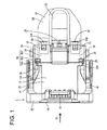
FIG. 1 is a plan view of a waterproof connector according to an embodiment showing a state where a wire cover is mounted, -
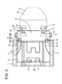
FIG. 2 is a bottom view showing the waterproof connector in the state where wire cover is mounted, -
FIG. 3 is a front view showing the waterproof connector, -
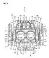
FIG. 4 is a rear view showing the waterproof connector, -
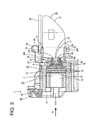
FIG. 5 is a section corresponding to a section along A-A ofFIG. 3 showing the waterproof connector, -
FIG. 6 is a side view of a seal ring, -
FIG. 7 is a plan view of the seal ring, and -
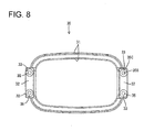
FIG. 8 is a rear view of the seal ring. - One specific embodiment of the present invention is described with reference to
FIGS. 1 to 8 . - A fluid- or waterproof connector C in this embodiment includes a
housing 10 connectable to a housing of a mating connector (not shown), and at least oneseal ring 30 to be sandwiched or clamped between the mating housing and thehousing 10 to seal between them is mounted on thishousing 10. This fluid- or waterproof connector C particularly is a lever-type connector with a lever 40 (as a particular movable member), and awire cover 50 for at least partly covering one or more wires (not shown) drawn out from the waterproof connector C is mounted particularly on a rear end part. Note that, in the following description, a side of thehousing 10 to be connected to the mating housing and an opposite side thereof are respectively referred to as a front side and a rear side, and upper and lower sides ofFIG. 3 are respectively referred to as upper and lower sides. - The
housing 10 of the waterproof connector C is made e.g. of synthetic resin and an integral or unitary assembly of a terminal accommodatingportion 11 in which one or more unillustrated terminal fittings are to be at least partly accommodated and areceptacle 12 provided at least partly around thisterminal accommodating portion 11. - The terminal
accommodating portion 11 particularly substantially is in the form of a block having a laterally long rectangular or polygonal or oval cross-section as a whole, and the one or more terminal fittings (not shown) can be individually accommodated therein. - The
receptacle 12 particularly substantially is in the form of a tube at least partly surrounding theterminal accommodating portion 11, and the front end thereof particularly is located more forward than that of theterminal accommodating portion 11 so that the terminalaccommodating portion 11 particularly can be substantially entirely covered (seeFIG. 5 ). Thereceptacle 12 is connected to (particularly a rear end part of) theterminal accommodating portion 11 by at least one connecting wall (locking wall) 13, and a space enclosed by theterminal accommodating portion 11, thereceptacle 12 and the connectingwall 13 serves as abottomed connection space 14 into which theseal ring 30 and the mating housing at least partly are fittable substantially from front (i.e. a connection side). An area of the outer peripheral surface of theterminal accommodating portion 11 from a joined position with the connectingwall 13 to a position somewhat before has no unevenness on the surface, so that theseal ring 30 is easily held in close contact. - The
seal ring 30 made of a resilient material (e.g. rubber) is to be mounted in the connection space 14 (seeFIG. 3 ). Theseal ring 30 particularly is in the form of a circular or oval or rounded polygonal ring and to be at least partly accommodated in in theconnection space 14, particularly at a back end position of theconnection space 14, and the inner peripheral surface thereof is held in close contact with the outer peripheral surface of theterminal accommodating portion 11. One or more, particularly a plurality oflips 31 are provided on the inner and/or outer peripheral surfaces (particularly on each of the inner and outer peripheral surfaces) of theseal ring 30. When the mating connector is connected to the waterproof connector C, a receptacle of the unillustrated mating housing at least partly is inserted into theconnection space 14 of thehousing 10, a leading end part of the receptacle is inserted into a space between the outer peripheral surface of theseal ring 30 and the inner peripheral surface of thereceptacle 12 and the seal ring 30 (particularly the lip(s) 31 provided on the inner and/or outer peripheral surfaces of the seal ring 30) are squeezed and pressed against the inner peripheral surface of the receptacle and the outer peripheral surface of theterminal accommodating portion 11. In this way, a fluid- or waterproof property between thehousing 10 and the mating housing is maintained. - One or more
pressing portions 32 against which an assembling jig is to be pressed in inserting theseal ring 30 into theconnection space 14 are provided on the outer peripheral surface of the seal ring 30 (seeFIG. 7 ). Specifically, one or more, particularly a pair ofpressing portions 32 substantially in the form of flat plates are provided on theseal ring 30, particularly substantially at longitudinally symmetrical positions of theseal ring 30. Eachpressing portion 32 is formed to substantially project radially outward from (particularly a rear end part of) the outer peripheral surface of theseal ring 30 and/or sized such that the projecting end thereof reaches the inner peripheral surface of thereceptacle 12. - One or
more locking projections 33 to be engaged with the connectingwall 13 of thehousing 10 are provided on (particularly the rear surfaces of) thepressing portions 32. Specifically, one or more, particularly a pair of lockingprojections 32 are provided on eachpressing portion 32 and/or vertically spaced apart by a specified (predetermined or predeterminable) distance on each pressing portion 32 (seeFIGS. 6 and8 ). - The locking
projection 33 is composed of or comprises ashaft portion 34 projecting from the pressing portion 32 (particularly substantially projecting backward from the rear surface of the pressing portion 32) and ahead portion 35 provided on the rear or distal end of thisshaft portion 34. Theshaft portion 34 particularly substantially is in the form of a cylinder whose axis line extends along an inserting direction ID of theseal ring 30, and/or substantially projects backward by as much as the thickness of the connectingwall 13 from the rear surface of thepressing portion 32. - Specifically, the
head portion 35 particularly is formed to have a somewhat larger diameter (or sectional area) than theshaft portion 34, substantially projects in all directions from theshaft portion 34 and/or has a substantially circular cross-section one size larger than the shaft portion 34 (seeFIGS. 6 and7 ). Thehead portion 35 penetrates through the connectingwall 13 while resiliently contracting, and substantially is restored to its original shape to be engaged with the rear surface of the connectingwall 13. Thehead portion 35 includes abase end part 35A which is an end part on theshaft portion 34 side, aleading end part 35B which is an end part opposite to theshaft portion 34 and/or anintermediate part 35C which is a part between thebase end part 35A and theleading end part 35B. Specifically, thebase end part 35A of thehead portion 35 substantially is formed into a disk shape having a constant diameter in an axial direction (insertion direction ID), theintermediate part 35C substantially is formed into a conical or tapered shape tapered from thebase end part 35A toward theleading end part 35B, and theleading end part 35B substantially is formed into a cylindrical shape having a small diameter. - The connecting
wall 13 of thehousing 10 is formed with one or morefitting recesses 15 into which the one or more respectivepressing portions 32 of theseal ring 30 are to be at least partly fitted (seeFIG. 5 ). The fitting recesses 15 particularly are formed in the front surface of the connectingwall 13 and particularly have a depth substantially equivalent to the thickness of thepressing portions 32. Parts (called backwall portions 13A) of the connectingwall 13 located behind thefitting recesses 15 are formed to project slightly more backward than the other parts of the connectingwall 13 to ensure a specified (predetermined or predeterminable) wall thickness. - Further, one or more locking holes 16 to be engaged with the locking
projections 33 provided on theseal ring 30 substantially are formed to penetrate through the connectingwall 13 of thehousing 10 in forward and backward directions (seeFIG. 5 ). Specifically, a plurality of lockingholes 16 are formed at positions substantially aligned with the lockingprojections 33 of theseal ring 30 and/or penetrate through theback wall portions 13A of the connectingwall 13. A pair of lockingholes 16 are provided at each of substantially symmetrical positions at the opposite sides of theterminal accommodating portion 11. The pair of lockingholes 16 located lateral to theterminal accommodating portion 11 particularly are vertically spaced apart by a specified (predetermined or predeterminable) distance. - One or more resilient (particularly rubber) plug
fitting portions 17 into which one or more unillustrated resilient (rubber) plugs mounted on end portions of respective wires are to be fitted are provided behind the connectingwall 13 of the housing 10 (behind the terminal accommodating portion 11) (seeFIG. 4 ). The resilient (rubber) plugfitting portion 17 particularly substantially is in the form of a cylindrical tube, projects backward from the connectingwall 13 and/or is open backward. The resilient (rubber) plug fitted into the resilient (rubber) plugfitting portion 17 is to be held in close contact with the outer peripheral surface of the wire and the inner peripheral surface of the resilient (rubber) plugfitting portion 17 particularly over the substantially entire circumference and seals between these outer and inner peripheral surfaces in a fluid- or liquid-tight manner. - Further, at least one
protection wall 18 standing up or projecting close to or substantially around thehead portions 35 of the lockingprojections 33 is provided behind or adjacent to the connectingwall 13 of the housing 10 (seeFIG. 4 ). Theprotection wall 18 particularly is provided along the lateral edges (particularly left and/or right edge(s) and/or the upper and/or lower edge(s)) of thehousing 10 and/or substantially in the form of a laterally long rectangular tube. The rear end of theprotection wall 18 particularly is located behind those of the locking projections 33 (seeFIG. 5 ) so that thehead portions 35 of the lockingprojections 33 are protected particularly by being substantially entirely covered by theprotection wall 18. - One or more reinforcing
walls protection wall 18 and the resilient (rubber) plug fitting portions 17 (seeFIG. 4 ). The reinforcingwalls side reinforcing walls 19A vertically connecting intermediate portions (particularly the centers) of the resilient (rubber) plugfitting portions 17 in a width direction to theprotection wall 18 and end-side reinforcing walls 19B vertically connecting end parts of the resilient (rubber) plugfitting portions 17 in the width direction to theprotection wall 18. Specifically, a pair of the central-side and end-side reinforcing walls fitting portion 17. The interior of theprotection wall 18 particularly is partitioned into a plurality of areas by the one or more reinforcingwalls fitting portions 17. Note that a part of theprotection wall 18 between the pair of central-side reinforcing walls 19A provided above the resilient (rubber) plugfitting portions 17 particularly is cut off to form afinger inserting portion 21 into which a fingertip is to be inserted particularly in unlocking thelever 40 at a connection position. - The
head portions 35 of theseal ring 30 are arranged in spaces (referred to as locking projection accommodating portions 22) at least partly enclosed by theprotection wall 18, the resilient (rubber) plugfitting portions 17 and/or the end-side reinforcing walls 19B out of the space in theprotection wall 18. - The locking
projection accommodating portion 22 particularly includes one ormore guide grooves 23 into which aguide piece 54 of thewire cover 50 to be described later is to be at least partly inserted. Theguide grooves 23 particularly are grooves provided along the end-side reinforcing walls 19B in the lockingprojection accommodating portion 22. Theguide grooves 23 are provided at upper and/or lower sides of the lockingprojection accommodating portion 22 and/or have a width narrower than other parts of the lockingprojection accommodating portions 22. Opposite edge parts of theguide piece 54 in the width direction are to be at least partly inserted into the upper andlower guide grooves 23, and thehead portions 35 of the lockingprojections 33 are arranged in a central or intermediate part of the lockingprojection accommodating portion 22 excluding theguide grooves 23. Note thatwindow portions 26 particularly are formed to penetrate through theprotection wall 18 near therespective head portions 35. Thesewindow portions 26 are described in detail later. - As shown in
FIGS. 1 and2 , one or more mountingprojections 24 to be engaged with one or more respective mountingpieces 53 of thewire cover 50 to be described later project on the outer peripheral wall of theprotection wall 18. The mounting projection(s) 24 is/are located at an open end part (rear end part) of theprotection wall 18. Specifically, a pair of mountingprojections 24 are provided at central or intermediate sides of the end-side reinforcing walls 19B on each of the upper and lower surfaces of the protection wall 18 (seeFIG. 4 ). - The
lever 40 is made e.g. of synthetic resin and includes one or more, particularly a pair ofarm portions 41 substantially arranged along the lateral (left and/or right) wall(s) of thehousing 10 and an operatingportion 42 at a distal side thereof, particularly connecting the botharm portions 41 to each other. Thelever 40 is displaceable (particularly rotatable or pivotable) between an initial position (seeFIG. 5 ) and a connection position (not shown). When the mating connector is connected with thelever 40 held at the initial position, one or more cam pins (as a particular cam member) of the mating connector at least partly enter one or morerespective cam grooves 41A (as a particular mating cam member) formed in the arm portion(s) 41. As thelever 40 is displaced (particularly rotated or pivoted), the cam pin(s) and the cam groove(s) 41A are engaged to exhibit a cam action which connects the connector with the mating connector or assists their connection. When thelever 40 reaches the connection position, the mating connector and the fluid- or waterproof connector C reach a properly connected state and, substantially simultaneously, alock portion 43 provided on the operatingportion 42 particularly is engaged with an engagingportion 25 provided on thehousing 10, whereby thelever 40 is locked in a state where a displacement (particularly rotational movement) thereof toward the initial position is prevented. Note that the mating connector and the fluid- or waterproof connector C are separated or their separation is assisted by displacing (particularly rotating or pivoting) thelever 40 from the connection position toward or to the initial position. - The
wire cover 50 is made e.g. of synthetic resin and includes a covermain body 51 for at least partly covering the one or more wires. A wire draw-outopening 52 through which the one or more wires are drawn out laterally (e.g. upward) is provided on the lateral (upper) surface of the cover main body 51 (seeFIG. 1 ). The wire draw-outopening 52 particularly has a substantially rectangular or polygonal shape and/or is open on a side to be mounted to thehousing 10. - The
wire cover 50 includes the one or more mountingpieces 53 to be engaged with the one or morerespective mounting projections 24 of thehousing 10 and/or the one ormore guide pieces 54 to be at least partly inserted into the one or morerespective guide grooves 23. - Specifically, a pair of mounting
pieces 53 are provided on each of the upper and lower surfaces of the wire cover 50 (seeFIGS. 1 and2 ), wherein the upper mountingpieces 53 are provided at substantially opposite sides of the wire draw-outopening 52 and thelower mounting pieces 53 are provided at positions substantially facing the upper mountingpieces 53. As shown inFIG. 5 , the mountingpiece 53 particularly substantially is in the form of a flat plate extending substantially along the outer peripheral wall of theprotection wall 18 of thehousing 10, includes a mountinghole 53A into which the mountingprojection 24 at least partly is fittable and is resiliently deformable vertically or towards and away from theprotection wall 18. By engaging the mountingpieces 53 of thewire cover 50 with the mountingprojections 24 of thehousing 10, thewire 50 is mounted and held on the fluid- or waterproof connector C. - One or more, particularly a pair of
guide pieces 54 are provided at the wire cover 50 (particularly at substantially opposite ends of thewire cover 50 in the width direction, seeFIGS. 1 and2 ). The guide piece(s) 54 particularly is/are in the form of thin plate(s) and project(s) more forward than the mounting piece(s) 53. When the guide piece(s) 54 is/are at least partly inserted into the locking projection accommodating portion(s) 22 of theprotection wall 18, portion(s) thereof (particularly the substantially opposite edge parts thereof in the width direction) is/are at least partly inserted into the guide groove(s) 23, whereby a mounting operation of thewire cover 50 is guided. The leading end(s) of the guide piece(s) 54 inserted into the locking projection accommodating portion(s) 22 is/are spaced backward from the head portion(s) 35 of the locking projection(s) 33 to prevent the interference of the guide piece(s) 54 and the locking projection(s) 33. - The
protection wall 18 particularly is formed with the one ormore window portions 26 penetrating through theprotection wall 18 near the respective head portion(s) 35 (seeFIGS. 1 and2 ). The window portion(s) 26 particularly is/are formed on end part(s) of a front side of theprotection wall 18, i.e. right behind the connectingwall 13. Asmany window portions 26 as the lockingprojections 33 are provided. Specifically, a pair ofwindow portions 26 are arranged adjacent to and/or at upper and lower sides of the locking projection accommodating portion 22 (seeFIG. 5 ). This pair ofwindow portions 26 particularly are formed at positions substantially facing each other across thehead portions 35 and, when thehead portions 35 are not present therebetween, thehousing 10 can be looked through from top to bottom through the pair ofwindow portions 26. Note that, by forming thewindow portions 26 in the upper and lower walls of theprotection wall 18, thewindow portions 26 can be formed by slide molds for forming the mountingprojections 24. - Each
window portion 26 particularly is a rectangular opening slightly longer in the width direction of the housing 10 (seeFIGS. 1 and2 ). A dimension of thewindow portion 26 in the width direction (dimension in a longer direction) is larger than the width of thehead portion 35 and/or substantially equal to the width of a widened part of the locking projection accommodating portion 22 (spacing between the end-side reinforcing wall 19B and a thin part of the protection wall 18). Further, a dimension of thewindow portion 26 in a height direction (dimension in a shorter direction) particularly is substantially equal to the sum of the height of a step part of theback wall portion 13A (part projecting more backward than the other part of the connecting wall 13) and a total dimension of thebase end part 35A and theintermediate part 35C of thehead portion 35 of the lockingprojection 33 in the axial direction as shown inFIGS. 1 and2 , and thebase end part 35A and theintermediate part 35C can be visually confirmed from a lateral side of theprotection wall 18 via thewindow portion 26. - Next, functions and effects of this embodiment configured as described above are described.
- The fluid- or waterproof connector C of this embodiment is such that the
seal ring 30 mounted on thehousing 10 is to be sandwiched or clamped or squeezed between thishousing 10 and the connectable mating housing to seal between thehousing 10 and the mating housing. Theseal ring 30 includes one or more, particularly a plurality of lockingprojections 33 to be engaged with the connectingwall 13 provided in thehousing 10. The (particularly each) lockingprojection 33 includes the shaft portion 344 and thehead portion 35 substantially projecting toward the opposite sides from thisshaft portion 34. The head portion(s) 35 is/are passed through the connectingwall 13 and engaged with the rear surface of the connectingwall 13. Theprotection wall 18 standing up or projects substantially around the head portion(s) 35 is provided behind the connectingwall 13 and formed with the window portion(s) 26 penetrating through theprotection wall 18 near the respective head portion(s) 35. - Since the presence or absence of the
head portion 35 of each lockingprojection 33, the presence or absence of a missing part of thehead portion 35 and the like can be visually confirmed by looking at the interior of theprotection wall 18 through eachwindow portion 26 by this arrangement, a missing part and a lost part of theseal ring 30 can be easily confirmed. Note that it is possible to conduct not only an inspection by visual confirmation, but also an inspection of confirming whether or not a jig pin comes into contact with thehead portion 35 by piercing or inserting the jig pin into thewindow portion 26, an image inspection from thewindow portion 26 and the like. - The
window portions 26 particularly are formed on or near the end parts of the front side of theprotection wall 18. Here, if the fluid- or waterproof connector C is used in such a posture that the rear end faces upward (such a posture that theprotection wall 18 is open upward), fluid or water tends to pool inside theprotection wall 18. Thus, a sealing property may be reduced. However, since thewindow portions 26 particularly are formed on the end parts of the front side of theprotection wall 18, fluid or water inside theprotection wall 18 is or can be drained to the outside through thewindow portions 26 in such a case, wherefore a reduction in the sealing property can be prevented. - Further, the
base end parts 35A of thehead portions 35 particularly can be visually confirmed through thewindow portions 26. This makes it easier to confirm whether or not theentire head portions 35 are passed through the connectingwall 13, i.e. whether or not the lockingprojections 33 are completely engaged with the connectingwall 13. Thus, not only a missing part and a lost part of theseal ring 30, but also engaged states of the lockingprojections 33 can be easily confirmed. Further, since the engaged states of the lockingprojections 33 can be easily confirmed without unnecessarily making thewindow portions 26 larger, sufficient strength can be ensured for theprotection wall 18 that serves as a mounting portion for thewire cover 50. - Further, the protection wall particularly 18 is formed with the pair of
window portions 26 at positions substantially facing each other across thehead portions 35. Since this enables the presence or absence of thehead portions 35 to be inspected based on whether or not a laser beam passes through the pair ofwindow portions 26, an inspection by a laser beam can also be easily conducted. - Accordingly, to provide a waterproof connector in which a missing part and a lost part of a seal ring can be easily confirmed, in a fluidproof connector C, a
seal ring 30 mounted on ahousing 10 is sandwiched or clamped or squeezed between thehousing 10 and a connectable mating housing to seal between thehousing 10 and the mating housing. Theseal ring 30 includes one or more, particularly a plurality of lockingprojections 33 to be engaged with a lockingwall 13 provided in thehousing 10. The (particularly each) lockingprojection 33 includes ashaft portion 34 and a head portion 35 (having a larger cross-sectional area than the shaft portion) particularly projecting toward substantially opposite sides from theshaft portion 34 and thehead portion 35 is passed through the lockingwall 13 to be engaged with the rear surface of the lockingwall 13. At least oneprotection wall 18 standing up or projecting adjacent to or at least partly around thehead portions 35 is provided behind or adjacent to the lockingwall 13. Theprotection wall 18 is formed with one ormore window portions 26 penetrating through theprotection wall 18 near the respective head portion(s) 35. - The present invention is not limited to the above described and illustrated embodiment. For example, the following embodiments are also included in the technical scope of the present invention.
- (1) Although the waterproof connector C is a lever-type connector in the above embodiment, the present invention can also be applied to a connector without a lever.
- (2) Although the
wire cover 50 is to be mounted on the waterproof connector C in the above embodiment, the present invention can also be applied to a connector on which no wire cover is to be mounted. - (3) In the above embodiment, the
wire cover 50 is to be mounted on theprotection wall 18. Without being limited to this, a wire cover may be mounted on a part of the housing other than the protection wall. - (4) In the above embodiment, the
seal ring 30 is mounted on the outer peripheral surface of theterminal accommodating portion 11 and sandwiched between the outer peripheral surface of thisterminal accommodating portion 11 and the inner peripheral surface of a skirt portion. Without being limited to this, a seal member may be mounted on the inner peripheral surface of the receptacle and sandwiched between the inner peripheral surface of the receptacle and the outer peripheral surface of the skirt portion. In this case, pressing portions may be formed to project on the inner peripheral side of the seal member. - (5) In the above embodiment, the
head portion 35 projects from theshaft portion 34 in all directions and has a (particularly substantially circular) cross-section one size larger than theshaft portion 34. Without being limited to this, a head portion may be, for example, in the form of a thin plate projecting toward substantially opposite sides from the shaft portion or a plurality of thin plates substantially may radially project from the shaft portion as a center. - (6) In the above embodiment, the
window portions 26 are formed on the end parts of the front side of theprotection wall 18. Without being limited to this, window portions may not be necessarily formed on the end parts of the front side of the protection wall as long as they are formed near the respective head portions. Even in such a case, the window portions function as water drainage holes, for example, if the waterproof connector is used in a transverse posture. - (7) In the above embodiment, the
window portions 26 are formed above and below the lockingprojection accommodating portions 22. Without being limited to this, window portions may be formed lateral to the locking projection accommodating portions. -
- C ...
- waterproof connector
- 10 ...
- housing
- 13 ...
- connecting wall (locking wall)
- 18 ...
- protection wall
- 22 ...
- locking projection accommodating portion
- 26 ...
- window portion
- 30 ...
- seal ring
- 33 ...
- locking projection
- 34 ...
- shaft portion
- 35 ...
- head portion
- 35A ...
- base end part (end part on shift portion side)
Claims (15)
- A fluidproof connector (C) configured such that a seal ring (30) to be mounted on a housing (10) is sandwiched between the housing (10) and a connectable mating housing to seal between the housing (10) and the mating housing, wherein:the seal ring (30) includes one or more locking projections (33) to be engaged with a locking wall (13) provided in the housing (10);the locking projection (33) includes a shaft portion (34) and a head portion (35) projecting from the shaft portion (34) and the head portion (35) is passed through the locking wall (13) to be engaged with the rear surface of the locking wall (13);at least one protection wall (18) projecting at least partly around the head portion(s) (35) is provided behind the locking wall (13); andthe protection wall (18) is formed with one or more window portions (26) penetrating through the protection wall (18) near the respective head portion(s) (35).
- A fluidproof connector according to claim 1, wherein the one or more window portions (26) are formed at or near end part(s) of a front side of the protection wall (18).
- A fluidproof connector according to any one of the preceding claims, wherein at least end part(s) (35A) of the head portion(s) (35) on the shaft portion side(s) are visually confirmable through the window portion(s) (26).
- A fluidproof connector according to any one of the preceding claims, wherein the protection wall (18) is formed with a pair of window portions (26) at positions substantially facing each other across the head portion(s) (35).
- A fluidproof connector according to any one of the preceding claims, wherein the window portion (26) substantially is a rectangular opening slightly longer in the width direction of the housing (10).
- A fluidproof connector according to any one of the preceding claims, wherein a dimension of the window portion (26) in the width direction is larger than the width of the head portion (35) and/or substantially equal to the width of a widened part of a locking projection accommodating portion (22) for the head portion (35).
- A fluidproof connector according to any one of the preceding claims, wherein a rear end of the protection wall (18) is located behind a rear end of the locking projection (33) so that the head portion (35) of the locking projection (33) is protected particularly by being substantially entirely covered by the protection wall (18).
- A fluidproof connector according to any one of the preceding claims, wherein a movable member (40) is provided to display a cam action for connecting the connector (C) with the mating connector or assisting their connection.
- A fluidproof connector according to any one of the preceding claims, wherein one or more lips (31) are provided on the inner and/or outer peripheral surfaces of the seal ring (30).
- A fluidproof connector according to any one of the preceding claims, wherein the head portion (35) includes a base end part (35A) which is an end part on the shaft portion (34) side, a leading end part (35B) which is an end part opposite to the shaft portion (34) and/or an intermediate part (35C) which is a part between the base end part (35A) and the leading end part (35B).
- A fluidproof connector according to any one of the preceding claims, wherein one or more resilient plug fitting portions (17) into which one or more resilient plugs mounted on end portions of respective wires are to be fitted are provided behind the locking wall (13) of the housing (10).
- A fluidproof connector according to any one of the preceding claims, wherein one or more reinforcing walls (19A; 19B) are provided between the protection wall (18) and one or more portions (17) of the housing (10).
- A fluidproof connector according to any one of the preceding claims, wherein a wire cover (50) is provided including a cover main body (51) for at least partly covering the one or more wires and a wire draw-out opening (52) through which the one or more wires are drawn out laterally.
- A method of assembling a fluidproof connector (C) configured such that a seal ring (30) to be mounted on a housing (10) is sandwiched between the housing (10) and a connectable mating housing to seal between the housing (10) and the mating housing, wherein:engaging the seal ring (30) includes one or more locking projections (33) with a locking wall (13) provided in the housing (10);a head portion (35) of the locking projection (33) projecting from a shaft portion (34) of the locking projection (33) through the locking wall (13) to engage the head portion (35) with the rear surface of the locking wall (13);providing at least one protection wall (18) projecting at least partly around the head portion(s) (35) behind the locking wall (13); andforming one or more window portions (26) penetrating through the protection wall (18) near the respective head portion(s) (35).
- A method according to claim 14, wherein the engagement of the head portion (35) with the locking wall (13) is confirmed through the window portion (26).
Applications Claiming Priority (1)
| Application Number | Priority Date | Filing Date | Title |
|---|---|---|---|
| JP2011252613A JP5733168B2 (en) | 2011-11-18 | 2011-11-18 | Waterproof connector |
Publications (2)
| Publication Number | Publication Date |
|---|---|
| EP2595254A2 true EP2595254A2 (en) | 2013-05-22 |
| EP2595254A3 EP2595254A3 (en) | 2013-07-03 |
Family
ID=47177706
Family Applications (1)
| Application Number | Title | Priority Date | Filing Date |
|---|---|---|---|
| EP12006462.1A Withdrawn EP2595254A3 (en) | 2011-11-18 | 2012-09-14 | Fluidproof connector and assembling method therefor |
Country Status (3)
| Country | Link |
|---|---|
| EP (1) | EP2595254A3 (en) |
| JP (1) | JP5733168B2 (en) |
| CN (1) | CN103124020B (en) |
Cited By (2)
| Publication number | Priority date | Publication date | Assignee | Title |
|---|---|---|---|---|
| US11043772B2 (en) * | 2019-03-20 | 2021-06-22 | Yazaki Corporation | Connector with cable cover |
| US11070003B2 (en) * | 2019-03-15 | 2021-07-20 | Yazaki Corporation | Connector with cable cover |
Families Citing this family (3)
| Publication number | Priority date | Publication date | Assignee | Title |
|---|---|---|---|---|
| JP6607135B2 (en) * | 2016-04-12 | 2019-11-20 | 住友電装株式会社 | connector |
| JP6672995B2 (en) * | 2016-04-27 | 2020-03-25 | 住友電装株式会社 | Waterproof connector |
| CN109449657B (en) * | 2017-09-01 | 2021-03-23 | 中航光电科技股份有限公司 | Connectors, cage nuts and connector assemblies with seal viewing structure |
Citations (2)
| Publication number | Priority date | Publication date | Assignee | Title |
|---|---|---|---|---|
| US5779493A (en) * | 1995-11-07 | 1998-07-14 | Yazaki Corporation | Waterproofing connector |
| JP2006156081A (en) | 2004-11-29 | 2006-06-15 | Sumitomo Wiring Syst Ltd | Watertight connector |
Family Cites Families (5)
| Publication number | Priority date | Publication date | Assignee | Title |
|---|---|---|---|---|
| JP4193711B2 (en) * | 2004-01-28 | 2008-12-10 | 住友電装株式会社 | Waterproof connector |
| JP2006120352A (en) * | 2004-10-19 | 2006-05-11 | Sumitomo Wiring Syst Ltd | Connector |
| JP2006147474A (en) * | 2004-11-24 | 2006-06-08 | Sumitomo Wiring Syst Ltd | Waterproof connector |
| JP4985194B2 (en) * | 2007-08-01 | 2012-07-25 | 住友電装株式会社 | connector |
| CN102097708A (en) * | 2009-12-09 | 2011-06-15 | 苏州华旃航天电器有限公司 | Rapid sealing waterproof electric coupler assembly |
-
2011
- 2011-11-18 JP JP2011252613A patent/JP5733168B2/en not_active Expired - Fee Related
-
2012
- 2012-09-14 EP EP12006462.1A patent/EP2595254A3/en not_active Withdrawn
- 2012-11-16 CN CN201210464504.XA patent/CN103124020B/en not_active Expired - Fee Related
Patent Citations (2)
| Publication number | Priority date | Publication date | Assignee | Title |
|---|---|---|---|---|
| US5779493A (en) * | 1995-11-07 | 1998-07-14 | Yazaki Corporation | Waterproofing connector |
| JP2006156081A (en) | 2004-11-29 | 2006-06-15 | Sumitomo Wiring Syst Ltd | Watertight connector |
Cited By (2)
| Publication number | Priority date | Publication date | Assignee | Title |
|---|---|---|---|---|
| US11070003B2 (en) * | 2019-03-15 | 2021-07-20 | Yazaki Corporation | Connector with cable cover |
| US11043772B2 (en) * | 2019-03-20 | 2021-06-22 | Yazaki Corporation | Connector with cable cover |
Also Published As
| Publication number | Publication date |
|---|---|
| CN103124020B (en) | 2016-03-30 |
| CN103124020A (en) | 2013-05-29 |
| EP2595254A3 (en) | 2013-07-03 |
| JP2013109892A (en) | 2013-06-06 |
| JP5733168B2 (en) | 2015-06-10 |
Similar Documents
| Publication | Publication Date | Title |
|---|---|---|
| EP2706621B1 (en) | Connector, connector assembly and assembly method | |
| EP1885030B1 (en) | A wire cover and an assembling method | |
| EP1873871B1 (en) | Electrical connector | |
| EP2610975B1 (en) | Unit comprising a wire fixing member and method of assembling it | |
| EP2587594A1 (en) | Seal member, charging connector provided thereof, and mounting method for a seal member | |
| JP4678227B2 (en) | connector | |
| US8038486B1 (en) | Connector | |
| JP4941745B2 (en) | connector | |
| EP2284957B1 (en) | Waterproof structure and waterproof connector | |
| EP2595254A2 (en) | Fluidproof connector and assembling method therefor | |
| EP1962390B1 (en) | A connector and a connector assembly | |
| EP2644910A1 (en) | Connector connecting bolt, connector and connector assembly | |
| EP2533370A2 (en) | Connector and assembling method therefor | |
| JP7323571B2 (en) | Holding structure for wires with terminals | |
| JP2008282631A (en) | Connector cover | |
| KR101740064B1 (en) | Connector | |
| EP2390963B1 (en) | Connector, connector assembly and connector production method | |
| JP5402861B2 (en) | connector | |
| US9004932B2 (en) | Connector having a sealing ring with projections positioned in recesses on an inner periphery of a tubular fitting | |
| JP6024611B2 (en) | connector | |
| EP1693932A1 (en) | A shielded connector, mating shielded connector and shielded connector assembly | |
| JP2012084350A (en) | Connector | |
| JP5573718B2 (en) | Waterproof connector | |
| KR101690801B1 (en) | connector | |
| JP2014211999A (en) | Lever type connector |
Legal Events
| Date | Code | Title | Description |
|---|---|---|---|
| PUAI | Public reference made under article 153(3) epc to a published international application that has entered the european phase |
Free format text: ORIGINAL CODE: 0009012 |
|
| AK | Designated contracting states |
Kind code of ref document: A2 Designated state(s): AL AT BE BG CH CY CZ DE DK EE ES FI FR GB GR HR HU IE IS IT LI LT LU LV MC MK MT NL NO PL PT RO RS SE SI SK SM TR |
|
| AX | Request for extension of the european patent |
Extension state: BA ME |
|
| PUAL | Search report despatched |
Free format text: ORIGINAL CODE: 0009013 |
|
| AK | Designated contracting states |
Kind code of ref document: A3 Designated state(s): AL AT BE BG CH CY CZ DE DK EE ES FI FR GB GR HR HU IE IS IT LI LT LU LV MC MK MT NL NO PL PT RO RS SE SI SK SM TR |
|
| AX | Request for extension of the european patent |
Extension state: BA ME |
|
| RIC1 | Information provided on ipc code assigned before grant |
Ipc: H01R 13/629 20060101ALN20130529BHEP Ipc: H01R 43/00 20060101ALN20130529BHEP Ipc: H01R 13/52 20060101AFI20130529BHEP |
|
| 17P | Request for examination filed |
Effective date: 20131031 |
|
| RBV | Designated contracting states (corrected) |
Designated state(s): AL AT BE BG CH CY CZ DE DK EE ES FI FR GB GR HR HU IE IS IT LI LT LU LV MC MK MT NL NO PL PT RO RS SE SI SK SM TR |
|
| 17Q | First examination report despatched |
Effective date: 20150224 |
|
| RIC1 | Information provided on ipc code assigned before grant |
Ipc: H01R 13/52 20060101AFI20170315BHEP Ipc: H01R 43/00 20060101ALN20170315BHEP Ipc: H01R 13/629 20060101ALN20170315BHEP |
|
| RIC1 | Information provided on ipc code assigned before grant |
Ipc: H01R 43/00 20060101ALN20170321BHEP Ipc: H01R 13/52 20060101AFI20170321BHEP Ipc: H01R 13/629 20060101ALN20170321BHEP |
|
| GRAP | Despatch of communication of intention to grant a patent |
Free format text: ORIGINAL CODE: EPIDOSNIGR1 |
|
| INTG | Intention to grant announced |
Effective date: 20170504 |
|
| STAA | Information on the status of an ep patent application or granted ep patent |
Free format text: STATUS: THE APPLICATION IS DEEMED TO BE WITHDRAWN |
|
| 18D | Application deemed to be withdrawn |
Effective date: 20170915 |