EP2595183A2 - Heat dissipation module - Google Patents
Heat dissipation module Download PDFInfo
- Publication number
- EP2595183A2 EP2595183A2 EP12192422.9A EP12192422A EP2595183A2 EP 2595183 A2 EP2595183 A2 EP 2595183A2 EP 12192422 A EP12192422 A EP 12192422A EP 2595183 A2 EP2595183 A2 EP 2595183A2
- Authority
- EP
- European Patent Office
- Prior art keywords
- heat pipe
- heat
- dissipation module
- heat dissipation
- supporting structure
- Prior art date
- Legal status (The legal status is an assumption and is not a legal conclusion. Google has not performed a legal analysis and makes no representation as to the accuracy of the status listed.)
- Granted
Links
Images



Classifications
-
- H—ELECTRICITY
- H10—SEMICONDUCTOR DEVICES; ELECTRIC SOLID-STATE DEVICES NOT OTHERWISE PROVIDED FOR
- H10W—GENERIC PACKAGES, INTERCONNECTIONS, CONNECTORS OR OTHER CONSTRUCTIONAL DETAILS OF DEVICES COVERED BY CLASS H10
- H10W40/00—Arrangements for thermal protection or thermal control
- H10W40/70—Fillings or auxiliary members in containers or in encapsulations for thermal protection or control
- H10W40/73—Fillings or auxiliary members in containers or in encapsulations for thermal protection or control for cooling by change of state
-
- F—MECHANICAL ENGINEERING; LIGHTING; HEATING; WEAPONS; BLASTING
- F28—HEAT EXCHANGE IN GENERAL
- F28D—HEAT-EXCHANGE APPARATUS, NOT PROVIDED FOR IN ANOTHER SUBCLASS, IN WHICH THE HEAT-EXCHANGE MEDIA DO NOT COME INTO DIRECT CONTACT
- F28D15/00—Heat-exchange apparatus with the intermediate heat-transfer medium in closed tubes passing into or through the conduit walls ; Heat-exchange apparatus employing intermediate heat-transfer medium or bodies
- F28D15/02—Heat-exchange apparatus with the intermediate heat-transfer medium in closed tubes passing into or through the conduit walls ; Heat-exchange apparatus employing intermediate heat-transfer medium or bodies in which the medium condenses and evaporates, e.g. heat pipes
- F28D15/0233—Heat-exchange apparatus with the intermediate heat-transfer medium in closed tubes passing into or through the conduit walls ; Heat-exchange apparatus employing intermediate heat-transfer medium or bodies in which the medium condenses and evaporates, e.g. heat pipes the conduits having a particular shape, e.g. non-circular cross-section, annular
-
- F—MECHANICAL ENGINEERING; LIGHTING; HEATING; WEAPONS; BLASTING
- F28—HEAT EXCHANGE IN GENERAL
- F28D—HEAT-EXCHANGE APPARATUS, NOT PROVIDED FOR IN ANOTHER SUBCLASS, IN WHICH THE HEAT-EXCHANGE MEDIA DO NOT COME INTO DIRECT CONTACT
- F28D15/00—Heat-exchange apparatus with the intermediate heat-transfer medium in closed tubes passing into or through the conduit walls ; Heat-exchange apparatus employing intermediate heat-transfer medium or bodies
- F28D15/02—Heat-exchange apparatus with the intermediate heat-transfer medium in closed tubes passing into or through the conduit walls ; Heat-exchange apparatus employing intermediate heat-transfer medium or bodies in which the medium condenses and evaporates, e.g. heat pipes
- F28D15/0275—Arrangements for coupling heat-pipes together or with other structures, e.g. with base blocks; Heat pipe cores
Definitions
- the invention relates to a heat dissipation module, and more particularly, to a heat dissipation module which directly contacts to an electronic element.
- a central processing unit (CPU) and a graphic processing unit (GPU) are often installed therein.
- CPU central processing unit
- GPU graphic processing unit
- the conventional heat dissipation module includes a heat-receiving portion, a heat pipe, and a heat sink.
- the heat receiving portion normally with an area larger than the electronic components, is disposed upon the electronic component, and a distance is formed therebetween.
- the heat pipe is accommodated in the heat-receiving portion, and the heat-receiving portion is connected to the heat sink via the heat pipe. Hence, the heat generated by the electronic components is received by the heat-receiving portion and further conducted to the heat sink via the heat pipe.
- the heat generated by the electronic components cannot be received by the heat pipe directly, which results in the heat dissipation efficiency of the conventional heat dissipation module not meeting the increasing heat removal requirements of modem heat-generating electronic components. Furthermore, with the arrangement of the heat-receiving portion, the thickness of the conventional heat dissipation module is increased, which hinders the development of thin and light-weight electronic device.
- one of the objectives of the present invention is to provide a heat dissipation module, wherein the heat generated by electronic components is directly received by a heat pipe so that the heat dissipation efficiency is increased.
- the other objective of the present invention is to decrease the thickness of the heat dissipation module so as to meet the demand of making a device using the same thinner.
- Still the other objective of the present invention is to reduce a number of necessary elements of the heat dissipation module, thus decreasing the weight and reducing the manufacturing cost of the heat dissipation module can be achieved by simplifying the manufacturing process.
- the heat dissipation module includes a supporting structure and a heat pipe.
- the supporting structure is adjacent to the heat electronic component.
- the heat pipe is connected to the supporting structure by soldering, and the bottom surface of the heat pipe is directly in contact with the upper surface of the electronic component. Between the two lateral surfaces of the groove, the heat pipe has a second width larger than that of or equal to the first width.
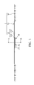
- FIG. 1 depicts a side view of a heat dissipation module in accordance with a first embodiment of the invention
- FIG. 2 is an explosive view of the heat dissipation module in accordance with the first embodiment of the invention
- FIG. 3 is an explosive view as viewed from lateral side of the heat dissipation module in accordance with the first embodiment of the invention
- FIG. 4 is a cross-sectional view taken along line A-A of FIG. in accordance with the first embodiment of the invention
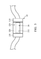
- FIG. 5 is a partial bottom view of the heat dissipation module in accordance with the first embodiment of the invention.
- FIG. 6 is an explosive view of a heat dissipation module in accordance with a second embodiment of the invention.
- the heat dissipation module 1 is used for an electronic component 50, to receive and dissipate heat generated from the electronic component 50.
- the electronic component 50 includes a base 52 and a central processing unit 54, hereinafter a CPU, wherein the base 52 is used for connection to a, for example, motherboard of a computer (not shown in FIGs.), and the CPU 54 is disposed on a substantial center of the base 52.
- the heat dissipation module 1 of the embodiment includes a supporting structure 10, a heat pipe 20, and a plurality of heat sinks 30.
- the supporting structure 10 includes two connecting portions 110 and two engaging portions 120.
- the two connecting portions 110 are respectively disposed at opposing sides of the base 52 of the electronic components 50, wherein both of the lateral surfaces of the two connecting portions 110 are inclined surfaces. In other words, along a direction away from the upper surface 111 of the two connecting portions 110, the distance between two connecting portions 110 increases gradually, which prevents contact between the two connecting portions 110 of the heat dissipation module 1 and the base 52 of the electronic component 50.
- the two connecting portions 110 are connected to each other via the two engaging portions 120, wherein the two engaging portions 120 are connected to the upper surfaces 111 of the two connecting portions 110.
- the two engaging portions 120 are respectively with a first thickness T 1 ( FIG. 3 ).
- the two lateral surfaces 121 and 122 of the two engaging portions 120 face each other, and a first width D 1 is formed between the two lateral surfaces 121 and 122, thereby a groove 125 is defined between the two lateral surfaces 121 and 122.
- a through hole, surrounded by the two connecting portions 110 and the two engaging portions 120 is formed at a substantial center of the supporting structure 10, wherein the electronic components 50 correspond to the through hole and is surrounded by the two connecting portions 110 and the two engaging portions 120.
- the two connecting portions 110 and the two engaging portions 120 of the supporting structure 10 are formed integrally.
- the supporting structure 10 can be comprised of aluminum, aluminum magnesium alloy or cast iron.
- the supporting structure 10 is comprised of aluminum to achieve the objective of making a light weight heat dissipation module 1.
- the heat pipe 20 is partially disposed in the groove 125 of the supporting structure 10, wherein the portion of the heat pipe 20 which is disposed in the groove 125 is with a thickness T 2 .
- the heat pipe 20 extends from the supporting structure 10 along two directions away from the supporting structure 10, and the heat sinks 30 are disposed on the two distal ends of the heat pipe 20 to increase the heat dissipating area.
- two 4-inch fans (not shown in FIGs.) relatively to the heat sink 30 are disposed on the surface of the heat sink 30 to increase the heat dissipation efficiency.
- the heat pipe 20 is soldered on the upper surfaces 111 of the two connecting portions 110 via a solder paste (not shown in FIGs.), but the soldering material is not limited thereto.
- a roller (not shown in FIGs.) is provided to press the upper surface 211 of the heat pipe 20 resulting in an extension of the heat pipe 20 toward the two corresponding lateral surfaces 121 and 122 of the two engaging portions 120.
- the heat pipe 20 is firmly engaged with the two corresponding lateral surfaces 121 and 122 of the two engaging portions 120. Specifically, after the rolling process, the heat pipe 20 between the two corresponding lateral surfaces 121 and 122 is with a second width D 2 , wherein the second width D 2 is slightly larger than or equals to the first width D 1 . Thus, after the heat pipe 20 is disposed in the groove 125, the heat pipe 20 is received in tight fit relation on the supporting structure 10.
- the bottom surface 124 of the engaging portion 120 and the bottom surface 212 of the heat pipe 20 are preferably located on one flat surface, but it is not limited thereto.
- the bottom surface 124 of the engaging portion 120 may also be higher than the bottom surface 212 of the heat pipe 20.
- the CPU 54 is accommodated in the two engaging portions 120. That is, the CPU 54 is accommodated within the groove 125 to further reduce the thickness of the heat dissipation module 1 after combining the electronic component 50.
- the heat generated from the CPU 54 may be partially conducted to the heat pipe 20 via the two connecting portions 110 and the two engaging portions 120.
- the upper surface 211 of the heat pipe 20 and the upper surfaces 123 of the two engaging portions 120 are preferably located on one flat surface. In general, the thickness T 1 of the two engaging portions 120 is larger than or equals to the thickness T 2 of the heat pipe 20.
- a gas gap may be formed between the heat pipe 20 and the electronic components 50 resulting in a decrease of heat dissipation efficiency therebetween.
- a thermal paste can be applied to be between the heat pipe 20 and the electronic components 50; thus, the heat dissipation efficiency can be further increased.
- the heat pipe 20 cannot be maintained with a straight structure, which prevents the CPU 54 from being firmly contacted to the heat pipe 20 and affects heat dissipation efficiency.
- the present invention provides a method as below.
- FIG. 6 shows a heat dissipation module 1' in accordance with a second embodiment of the invention, wherein elements substantially similar to that of the first embodiment are designated with like reference numbers and explanation that has been given already will be omitted in the following description.
- the heat dissipation module 1' further includes two flexure strips 60, wherein each of the flexure strips 60 includes a plurality of riveting holes 61 separately disposed thereon.
- the supporting structure 10' further includes a plurality of riveting points 127 corresponding to the riveting holes 61 disposed on the upper surface 123' of the engaging portions 120'.
- each of the flexure strips 60 provides a thrust force toward the electronic component 50 to allow the heat pipes 20 to contact the CPU 54 more reliably.
- the thrust force is passed to the heat pipe 20 to keep it straight; thus, the heat pipe 20 and the CPU 54 are contacted reliably and the heat conducting rate is increased.
- the heat pipe By direct contact between the heat pipe and the electronic component, heat generated from the electronic component can be dissipated by the heat dissipation module in an efficient way, and the thickness of the heat dissipation module can be reduced (in one exemplary embodiment, the thickness of a heat dissipation module of the present invention is 1.3 mm). Therefore, the objective of making a device using the same thinner can be achieved. Furthermore, thanks to the innovative mechanical feature of the supporting structure, the heat pipe can be disposed on the electronic component firmly and reliably effectuating an increase of heat dissipating efficiency.
Landscapes
- Engineering & Computer Science (AREA)
- Life Sciences & Earth Sciences (AREA)
- Sustainable Development (AREA)
- Physics & Mathematics (AREA)
- Thermal Sciences (AREA)
- Mechanical Engineering (AREA)
- General Engineering & Computer Science (AREA)
- Cooling Or The Like Of Semiconductors Or Solid State Devices (AREA)
- Cooling Or The Like Of Electrical Apparatus (AREA)
Abstract
Description
- This Application claims priority of Taiwan Patent Application No.
100141751, filed on November 16, 2011 - The invention relates to a heat dissipation module, and more particularly, to a heat dissipation module which directly contacts to an electronic element.
- In order to enable portable electronic devices to rapidly process a variety electronic signals, a central processing unit (CPU) and a graphic processing unit (GPU) are often installed therein. When the CPU or GPU operates at a high speed in the electronic device, its temperature is greatly increased. Thus, it is desirable to dissipate heat by using a heat dissipation module to allow the CPU or GPU and other electronic components to function within their normal operating temperature ranges, thereby assuring the quality of data management, storage and transfer operations.
- The conventional heat dissipation module includes a heat-receiving portion, a heat pipe, and a heat sink. The heat receiving portion, normally with an area larger than the electronic components, is disposed upon the electronic component, and a distance is formed therebetween. The heat pipe is accommodated in the heat-receiving portion, and the heat-receiving portion is connected to the heat sink via the heat pipe. Hence, the heat generated by the electronic components is received by the heat-receiving portion and further conducted to the heat sink via the heat pipe.
- However, due to structural limitations, the heat generated by the electronic components cannot be received by the heat pipe directly, which results in the heat dissipation efficiency of the conventional heat dissipation module not meeting the increasing heat removal requirements of modem heat-generating electronic components. Furthermore, with the arrangement of the heat-receiving portion, the thickness of the conventional heat dissipation module is increased, which hinders the development of thin and light-weight electronic device.
- Accordingly, one of the objectives of the present invention is to provide a heat dissipation module, wherein the heat generated by electronic components is directly received by a heat pipe so that the heat dissipation efficiency is increased. The other objective of the present invention is to decrease the thickness of the heat dissipation module so as to meet the demand of making a device using the same thinner. Still the other objective of the present invention is to reduce a number of necessary elements of the heat dissipation module, thus decreasing the weight and reducing the manufacturing cost of the heat dissipation module can be achieved by simplifying the manufacturing process.
- To achieve the above objectives, a heat dissipation module for an electronic component is provided by the present invention. The heat dissipation module includes a supporting structure and a heat pipe. The supporting structure is adjacent to the heat electronic component. The heat pipe is connected to the supporting structure by soldering, and the bottom surface of the heat pipe is directly in contact with the upper surface of the electronic component. Between the two lateral surfaces of the groove, the heat pipe has a second width larger than that of or equal to the first width.
- The invention can be more fully understood by reading the subsequent detailed description and examples with references made to the accompanying drawings, wherein:
-
FIG. 1 depicts a side view of a heat dissipation module in accordance with a first embodiment of the invention; -
FIG. 2 is an explosive view of the heat dissipation module in accordance with the first embodiment of the invention; -
FIG. 3 is an explosive view as viewed from lateral side of the heat dissipation module in accordance with the first embodiment of the invention; -
FIG. 4 is a cross-sectional view taken along line A-A of FIG. in accordance with the first embodiment of the invention; -
FIG. 5 is a partial bottom view of the heat dissipation module in accordance with the first embodiment of the invention; and -
FIG. 6 is an explosive view of a heat dissipation module in accordance with a second embodiment of the invention. - The following description is of the best-contemplated mode of carrying out the invention. This description is made for the purpose of illustrating the general principles of the invention and should not be taken in a limiting sense. The scope of the invention is best determined by reference to the appended claims
- Please refer to
FIGs. 1-3 . Theheat dissipation module 1 is used for anelectronic component 50, to receive and dissipate heat generated from theelectronic component 50. In on exemplary embodiment, theelectronic component 50 includes abase 52 and acentral processing unit 54, hereinafter a CPU, wherein thebase 52 is used for connection to a, for example, motherboard of a computer (not shown in FIGs.), and theCPU 54 is disposed on a substantial center of thebase 52. - The
heat dissipation module 1 of the embodiment includes a supportingstructure 10, aheat pipe 20, and a plurality ofheat sinks 30. The supportingstructure 10 includes two connectingportions 110 and twoengaging portions 120. The two connectingportions 110 are respectively disposed at opposing sides of thebase 52 of theelectronic components 50, wherein both of the lateral surfaces of the two connectingportions 110 are inclined surfaces. In other words, along a direction away from theupper surface 111 of the two connectingportions 110, the distance between two connectingportions 110 increases gradually, which prevents contact between the two connectingportions 110 of theheat dissipation module 1 and thebase 52 of theelectronic component 50. - The two connecting
portions 110 are connected to each other via the twoengaging portions 120, wherein the twoengaging portions 120 are connected to theupper surfaces 111 of the two connectingportions 110. The twoengaging portions 120 are respectively with a first thickness T1 (FIG. 3 ). The twolateral surfaces engaging portions 120 face each other, and a first width D1 is formed between the twolateral surfaces groove 125 is defined between the twolateral surfaces portions 110 and the twoengaging portions 120, is formed at a substantial center of the supportingstructure 10, wherein theelectronic components 50 correspond to the through hole and is surrounded by the two connectingportions 110 and the twoengaging portions 120. - In one exemplary embodiment, the two connecting
portions 110 and the twoengaging portions 120 of the supportingstructure 10 are formed integrally. The supportingstructure 10 can be comprised of aluminum, aluminum magnesium alloy or cast iron. Preferably, the supportingstructure 10 is comprised of aluminum to achieve the objective of making a light weightheat dissipation module 1. - The
heat pipe 20 is partially disposed in thegroove 125 of the supportingstructure 10, wherein the portion of theheat pipe 20 which is disposed in thegroove 125 is with a thickness T2. Theheat pipe 20 extends from the supportingstructure 10 along two directions away from the supportingstructure 10, and theheat sinks 30 are disposed on the two distal ends of theheat pipe 20 to increase the heat dissipating area. In one exemplary embodiment, two 4-inch fans (not shown in FIGs.) relatively to theheat sink 30 are disposed on the surface of theheat sink 30 to increase the heat dissipation efficiency. - Please refer to
FIGs. 2 ,4 , and5 . Details of the assembly process of theheat dissipation module 1 and a method of connecting theheat dissipation module 1 to theelectronic component 50 are described below. In one exemplary embodiment, theheat pipe 20 is soldered on theupper surfaces 111 of the two connectingportions 110 via a solder paste (not shown in FIGs.), but the soldering material is not limited thereto. Next, by a rolling process, a roller (not shown in FIGs.) is provided to press theupper surface 211 of theheat pipe 20 resulting in an extension of theheat pipe 20 toward the two correspondinglateral surfaces engaging portions 120. After the roller passes through theheat pipe 20 many times, theheat pipe 20 is firmly engaged with the two correspondinglateral surfaces engaging portions 120. Specifically, after the rolling process, theheat pipe 20 between the two correspondinglateral surfaces heat pipe 20 is disposed in thegroove 125, theheat pipe 20 is received in tight fit relation on the supportingstructure 10. - It is noted that, after the
heat pipe 20 is disposed on the supportingstructure 10, apartial bottom surface 212 among the two connectingportions 110 and the twoengaging portions 120 of theheat pipe 20 is exposed on the outside, as shown inFIG.5 . Therefore, when theelectronic component 50 is disposed at the substantial center of the two connectingportions 110, thebottom surface 212 of theheat pipe 20 is directly in contact with theupper surface 541 of theCPU 54. Hence, the heat generated from theCPU 54 is received by theheat pipe 20 directly and further conducted to theheat sink 30 disposed at the distal ends of theheat pipe 20 rapidly. On the other hand, because the corresponding lateral surfaces of the two connectingportions 110 of the supportingstructure 10 are two inclined surfaces, when theelectronic component 50 is disposed at the substantial center of the two connectingportions 110, thebase 52 is not to be contacted by the two connectingportions 110. - After the
heat pipe 20 is disposed on the supportingstructure 10, thebottom surface 124 of theengaging portion 120 and thebottom surface 212 of theheat pipe 20 are preferably located on one flat surface, but it is not limited thereto. Thebottom surface 124 of theengaging portion 120 may also be higher than thebottom surface 212 of theheat pipe 20. In this condition, theCPU 54 is accommodated in the twoengaging portions 120. That is, theCPU 54 is accommodated within thegroove 125 to further reduce the thickness of theheat dissipation module 1 after combining theelectronic component 50. Additionally, the heat generated from theCPU 54 may be partially conducted to theheat pipe 20 via the two connectingportions 110 and the twoengaging portions 120. Furthermore, theupper surface 211 of theheat pipe 20 and theupper surfaces 123 of the twoengaging portions 120 are preferably located on one flat surface. In general, the thickness T1 of the twoengaging portions 120 is larger than or equals to the thickness T2 of theheat pipe 20. - During the assembly process of the
heat pipe 20 and theelectronic components 50, a gas gap may be formed between theheat pipe 20 and theelectronic components 50 resulting in a decrease of heat dissipation efficiency therebetween. To fill the gap, a thermal paste can be applied to be between theheat pipe 20 and theelectronic components 50; thus, the heat dissipation efficiency can be further increased. On the other hand, due to insufficient mechanical strength of theheat pipe 20 and gravity effects, theheat pipe 20 cannot be maintained with a straight structure, which prevents theCPU 54 from being firmly contacted to theheat pipe 20 and affects heat dissipation efficiency. To solve this problem, the present invention provides a method as below. - Please refer to
FIG. 6. FIG. 6 shows a heat dissipation module 1' in accordance with a second embodiment of the invention, wherein elements substantially similar to that of the first embodiment are designated with like reference numbers and explanation that has been given already will be omitted in the following description. Compared with the heat dissipation module 1 (FIG. 1 ), the heat dissipation module 1' further includes twoflexure strips 60, wherein each of the flexure strips 60 includes a plurality ofriveting holes 61 separately disposed thereon. The supporting structure 10' further includes a plurality ofriveting points 127 corresponding to theriveting holes 61 disposed on theupper surface 123' of the engaging portions 120'. Theriveting points 127 are received in theriveting holes 61 so that the flexure strips 60 are connected to theupper surfaces 123' of the engaging portions 120'. Due to the ductility of the flexure strips 60, each of the flexure strips 60 provides a thrust force toward theelectronic component 50 to allow theheat pipes 20 to contact theCPU 54 more reliably. Specifically, because theheat pipe 20 is firmly engaged between the two engaging portions 120', while the flexure strips 60 provide thrust force to the two engaging portions 120', the thrust force is passed to theheat pipe 20 to keep it straight; thus, theheat pipe 20 and theCPU 54 are contacted reliably and the heat conducting rate is increased. - By direct contact between the heat pipe and the electronic component, heat generated from the electronic component can be dissipated by the heat dissipation module in an efficient way, and the thickness of the heat dissipation module can be reduced (in one exemplary embodiment, the thickness of a heat dissipation module of the present invention is 1.3 mm). Therefore, the objective of making a device using the same thinner can be achieved. Furthermore, thanks to the innovative mechanical feature of the supporting structure, the heat pipe can be disposed on the electronic component firmly and reliably effectuating an increase of heat dissipating efficiency.
- While the invention has been described by way of example and in terms of preferred embodiment, it is to be understood that the invention is not limited thereto. To the contrary, it is intended to cover various modifications and similar arrangements (as would be apparent to those skilled in the art). Therefore, the scope of the appended claims should be accorded the broadest interpretation so as to encompass all such modifications and similar arrangements.
Claims (15)
- A heat dissipation module for an electronic component, comprising:a supporting structure, adjacent to the electronic component; anda heat pipe, connected to the supporting structure by soldering, wherein the bottom surface of the heat pipe is directly in contact with the upper surface of the electronic component.
- The heat dissipation module as claimed in claim 1, wherein the supporting structure comprises two connecting portions, disposed on the two sides of the electronic component, and the heat pipe is disposed on the upper surface of the two connecting portions.
- The heat dissipation module as claimed in claim 2, wherein the supporting structure further comprises an engaging portion, and the two connecting portions are connected to each other via the engaging portion, and the heat pipe is engaged in the engaging portion.
- The heat dissipation module as claimed in claim 3, wherein the number of engaging portions is two, respectively disposed on two opposing sides of the heat pipe, wherein a first width is formed between the two engaging portions and the heat pipe has a second width larger than the first width.
- The heat dissipation module as claimed in claim 3, wherein the bottom surface of the engaging portion and the bottom surface of the heat pipe are located on one flat surface or the bottom surface of the engaging portion is higher than the bottom surface of the heat pipe.
- The heat dissipation module as claimed in claim 3, further comprising a flexure strip disposed on the engaging portion to provide a thrust force toward the electronic component.
- The heat dissipation module as claimed in claim 2, wherein along a direction away from the heat pipe, the distance between two connecting portions increases gradually.
- The heat dissipation module as claimed in claim 1, further comprising a plurality of heat sinks, wherein the heat pipe is extended from the supporting structure, and the heat sinks are disposed on the distal end of the heat pipe.
- A heat dissipation module for an electronic component, comprising:a supporting structure, comprising a groove formed on the upper surface of the supporting structure, wherein a first width is formed between two lateral surfaces of the groove; anda heat pipe, disposed in the groove of the supporting structure, and the bottom surface of the heat pipe is directly in contact with the upper surface of the electronic component,wherein between the two lateral surfaces of the groove, the heat pipe has a second width larger than that of or equal to the first width.
- The heat dissipation module as claimed in claim 9, wherein the supporting structure comprises:two connecting portions, disposed on two sides of the electronic component; andtwo engaging portions, connected between the two connecting portions, wherein the groove is formed between the two engaging portions.
- The heat dissipation module as claimed in claim 10, wherein the heat pipe is connected to the two connecting portions of the supporting structure by soldering.
- The heat dissipation module as claimed in claim 10, wherein the bottom surface of the engaging portion and the bottom surface of the heat pipe are located on one flat surface or the bottom surface of the engaging portion is higher than the bottom surface of the heat pipe.
- The heat dissipation module as claimed in claim 10, wherein along a direction away from the heat pipe, the distance between two connecting portions increases gradually.
- The heat dissipation module as claimed in claim 10, further comprising a flexure strip disposed on the engaging portion to provide a thrust force toward the electronic component.
- The heat dissipation module as claimed in claim 9, further comprising a plurality of heat sinks, wherein the heat pipe is extended from the supporting structure, and the heat sinks are disposed on the distal end of the heat pipe.
Applications Claiming Priority (1)
| Application Number | Priority Date | Filing Date | Title |
|---|---|---|---|
| TW100141751A TWI531303B (en) | 2011-11-16 | 2011-11-16 | Thermal module |
Publications (3)
| Publication Number | Publication Date |
|---|---|
| EP2595183A2 true EP2595183A2 (en) | 2013-05-22 |
| EP2595183A3 EP2595183A3 (en) | 2016-03-02 |
| EP2595183B1 EP2595183B1 (en) | 2019-07-24 |
Family
ID=47562964
Family Applications (1)
| Application Number | Title | Priority Date | Filing Date |
|---|---|---|---|
| EP12192422.9A Active EP2595183B1 (en) | 2011-11-16 | 2012-11-13 | Heat dissipation module |
Country Status (3)
| Country | Link |
|---|---|
| US (1) | US9087814B2 (en) |
| EP (1) | EP2595183B1 (en) |
| TW (1) | TWI531303B (en) |
Families Citing this family (8)
| Publication number | Priority date | Publication date | Assignee | Title |
|---|---|---|---|---|
| US20130114204A1 (en) * | 2011-11-04 | 2013-05-09 | Apple Inc. | Heat removal system for computing systems |
| US9390994B2 (en) * | 2013-08-07 | 2016-07-12 | Oracle International Corporation | Heat sinks with interdigitated heat pipes |
| US9327369B2 (en) * | 2014-03-11 | 2016-05-03 | Asia Vital Components Co., Ltd. | Method of manufacturing thermal module with enhanced assembling structure |
| CN104093293B (en) * | 2014-04-01 | 2017-10-27 | 东莞汉旭五金塑胶科技有限公司 | The chimeric composition and its preparation method of metallic heat radiating plate and heat pipe |
| EP3131376B1 (en) * | 2014-06-04 | 2021-08-04 | Huawei Technologies Co., Ltd. | Electronic device |
| US9498858B2 (en) | 2014-08-08 | 2016-11-22 | SEAKR Engineering, Inc. | System and method for dissipating thermal energy |
| DE102018121547B4 (en) | 2018-09-04 | 2026-02-19 | Dr. Ing. H.C. F. Porsche Aktiengesellschaft | Method and printed circuit board for heat and current conduction in power electronic circuits |
| US11425842B2 (en) * | 2020-09-14 | 2022-08-23 | Hewlett Packard Enterprise Development Lp | Thermal design of an access point |
Family Cites Families (17)
| Publication number | Priority date | Publication date | Assignee | Title |
|---|---|---|---|---|
| JPH0587475A (en) * | 1991-09-27 | 1993-04-06 | Furukawa Electric Co Ltd:The | Heat pipe type cooler |
| US6424528B1 (en) * | 1997-06-20 | 2002-07-23 | Sun Microsystems, Inc. | Heatsink with embedded heat pipe for thermal management of CPU |
| US6163073A (en) * | 1998-04-17 | 2000-12-19 | International Business Machines Corporation | Integrated heatsink and heatpipe |
| US7165603B2 (en) * | 2002-04-15 | 2007-01-23 | Fujikura Ltd. | Tower type heat sink |
| US7140422B2 (en) * | 2002-09-17 | 2006-11-28 | Hewlett-Packard Development Company, L.P. | Heat sink with heat pipe in direct contact with component |
| US7342788B2 (en) * | 2004-03-12 | 2008-03-11 | Powerwave Technologies, Inc. | RF power amplifier assembly with heat pipe enhanced pallet |
| CN100338767C (en) * | 2004-05-26 | 2007-09-19 | 鸿富锦精密工业(深圳)有限公司 | Heat pipe radiating unit and manufacturing method thereof |
| US7168152B1 (en) * | 2004-10-18 | 2007-01-30 | Lockheed Martin Corporation | Method for making an integrated active antenna element |
| TWM309143U (en) * | 2006-09-08 | 2007-04-01 | Micro Star Int Co Ltd | Circuit board with a perforated structure of a heat pipe |
| CN101212885B (en) * | 2006-12-27 | 2011-08-31 | 富准精密工业(深圳)有限公司 | Heat radiation module |
| CN101351109A (en) * | 2007-07-20 | 2009-01-21 | 富准精密工业(深圳)有限公司 | heat sink |
| CN101408301B (en) * | 2007-10-10 | 2012-09-19 | 富准精密工业(深圳)有限公司 | LED light fitting with heat radiating device |
| CN101605442B (en) * | 2008-06-13 | 2013-01-23 | 富准精密工业(深圳)有限公司 | heat sink |
| TWM361658U (en) | 2009-01-13 | 2009-07-21 | Hon Hai Prec Ind Co Ltd | Electrical connector assembly and clip thereof |
| TWM361659U (en) * | 2009-01-13 | 2009-07-21 | Hon Hai Prec Ind Co Ltd | Electrical connector assembly and clip thereof |
| US8353333B2 (en) * | 2009-08-04 | 2013-01-15 | Asia Vital Components Co., Ltd. | Board-shaped heat dissipating device and method of manufacturing the same |
| TWM410251U (en) | 2011-04-01 | 2011-08-21 | Asia Vital Components Co Ltd | Heat dissipation module |
-
2011
- 2011-11-16 TW TW100141751A patent/TWI531303B/en active
-
2012
- 2012-11-01 US US13/666,616 patent/US9087814B2/en active Active
- 2012-11-13 EP EP12192422.9A patent/EP2595183B1/en active Active
Non-Patent Citations (1)
| Title |
|---|
| None |
Also Published As
| Publication number | Publication date |
|---|---|
| TW201322899A (en) | 2013-06-01 |
| EP2595183B1 (en) | 2019-07-24 |
| US20130120937A1 (en) | 2013-05-16 |
| TWI531303B (en) | 2016-04-21 |
| US9087814B2 (en) | 2015-07-21 |
| EP2595183A3 (en) | 2016-03-02 |
Similar Documents
| Publication | Publication Date | Title |
|---|---|---|
| US9087814B2 (en) | Heat dissipation module | |
| US7640968B2 (en) | Heat dissipation device with a heat pipe | |
| US20080000619A1 (en) | Heat dissipation device | |
| US7701719B2 (en) | Fastening device for thermal module | |
| US6698500B2 (en) | Heat sink with fins | |
| US7130191B2 (en) | Function module with built-in heat dissipation device | |
| US20060138644A1 (en) | Thermal interface structure with integrated liquid cooling and methods | |
| EP2426711A2 (en) | Heat sink for a protrusion-type ic package | |
| US20080186685A1 (en) | Printed circuit board and semiconductor memory module using the same | |
| US20100025018A1 (en) | Heat dissipation device | |
| CN106959538B (en) | Heat radiation structure and display device | |
| US20090059526A1 (en) | Heat sink assembly and method manufacturing the same | |
| US20050000682A1 (en) | Heat dissipating fins of heat sink and manufacturing method thereof | |
| US20120000625A1 (en) | Heat dissipation device | |
| US20090175006A1 (en) | Honeycomb heat dissipating apparatus | |
| US7942195B2 (en) | Heat dissipation device having a bracket | |
| US7463484B2 (en) | Heatsink apparatus | |
| US7487825B2 (en) | Heat dissipation device | |
| EP3739285B1 (en) | Heat dissipation device and board card | |
| US20130070418A1 (en) | Heat dissipation module | |
| US20120312509A1 (en) | Heat dissipation device | |
| US20050121172A1 (en) | Composite heatsink for cooling of heat-generating element | |
| US20050083658A1 (en) | Heat dissipating module of an integrated circuit of a portable computer | |
| US9111910B2 (en) | Heat dissipation device with fin set | |
| US20100032136A1 (en) | Cooler module |
Legal Events
| Date | Code | Title | Description |
|---|---|---|---|
| PUAI | Public reference made under article 153(3) epc to a published international application that has entered the european phase |
Free format text: ORIGINAL CODE: 0009012 |
|
| AK | Designated contracting states |
Kind code of ref document: A2 Designated state(s): AL AT BE BG CH CY CZ DE DK EE ES FI FR GB GR HR HU IE IS IT LI LT LU LV MC MK MT NL NO PL PT RO RS SE SI SK SM TR |
|
| AX | Request for extension of the european patent |
Extension state: BA ME |
|
| PUAL | Search report despatched |
Free format text: ORIGINAL CODE: 0009013 |
|
| AK | Designated contracting states |
Kind code of ref document: A3 Designated state(s): AL AT BE BG CH CY CZ DE DK EE ES FI FR GB GR HR HU IE IS IT LI LT LU LV MC MK MT NL NO PL PT RO RS SE SI SK SM TR |
|
| AX | Request for extension of the european patent |
Extension state: BA ME |
|
| RIC1 | Information provided on ipc code assigned before grant |
Ipc: F28D 15/02 20060101ALI20160126BHEP Ipc: H01L 23/427 20060101AFI20160126BHEP |
|
| 17P | Request for examination filed |
Effective date: 20160831 |
|
| RBV | Designated contracting states (corrected) |
Designated state(s): AL AT BE BG CH CY CZ DE DK EE ES FI FR GB GR HR HU IE IS IT LI LT LU LV MC MK MT NL NO PL PT RO RS SE SI SK SM TR |
|
| STAA | Information on the status of an ep patent application or granted ep patent |
Free format text: STATUS: EXAMINATION IS IN PROGRESS |
|
| 17Q | First examination report despatched |
Effective date: 20170322 |
|
| GRAP | Despatch of communication of intention to grant a patent |
Free format text: ORIGINAL CODE: EPIDOSNIGR1 |
|
| STAA | Information on the status of an ep patent application or granted ep patent |
Free format text: STATUS: GRANT OF PATENT IS INTENDED |
|
| INTG | Intention to grant announced |
Effective date: 20190301 |
|
| GRAS | Grant fee paid |
Free format text: ORIGINAL CODE: EPIDOSNIGR3 |
|
| GRAA | (expected) grant |
Free format text: ORIGINAL CODE: 0009210 |
|
| STAA | Information on the status of an ep patent application or granted ep patent |
Free format text: STATUS: THE PATENT HAS BEEN GRANTED |
|
| AK | Designated contracting states |
Kind code of ref document: B1 Designated state(s): AL AT BE BG CH CY CZ DE DK EE ES FI FR GB GR HR HU IE IS IT LI LT LU LV MC MK MT NL NO PL PT RO RS SE SI SK SM TR |
|
| REG | Reference to a national code |
Ref country code: GB Ref legal event code: FG4D |
|
| REG | Reference to a national code |
Ref country code: CH Ref legal event code: EP |
|
| REG | Reference to a national code |
Ref country code: DE Ref legal event code: R096 Ref document number: 602012062220 Country of ref document: DE |
|
| REG | Reference to a national code |
Ref country code: AT Ref legal event code: REF Ref document number: 1159223 Country of ref document: AT Kind code of ref document: T Effective date: 20190815 |
|
| REG | Reference to a national code |
Ref country code: IE Ref legal event code: FG4D |
|
| REG | Reference to a national code |
Ref country code: NL Ref legal event code: MP Effective date: 20190724 |
|
| REG | Reference to a national code |
Ref country code: LT Ref legal event code: MG4D |
|
| REG | Reference to a national code |
Ref country code: AT Ref legal event code: MK05 Ref document number: 1159223 Country of ref document: AT Kind code of ref document: T Effective date: 20190724 |
|
| PG25 | Lapsed in a contracting state [announced via postgrant information from national office to epo] |
Ref country code: AT Free format text: LAPSE BECAUSE OF FAILURE TO SUBMIT A TRANSLATION OF THE DESCRIPTION OR TO PAY THE FEE WITHIN THE PRESCRIBED TIME-LIMIT Effective date: 20190724 Ref country code: NO Free format text: LAPSE BECAUSE OF FAILURE TO SUBMIT A TRANSLATION OF THE DESCRIPTION OR TO PAY THE FEE WITHIN THE PRESCRIBED TIME-LIMIT Effective date: 20191024 Ref country code: LT Free format text: LAPSE BECAUSE OF FAILURE TO SUBMIT A TRANSLATION OF THE DESCRIPTION OR TO PAY THE FEE WITHIN THE PRESCRIBED TIME-LIMIT Effective date: 20190724 Ref country code: FI Free format text: LAPSE BECAUSE OF FAILURE TO SUBMIT A TRANSLATION OF THE DESCRIPTION OR TO PAY THE FEE WITHIN THE PRESCRIBED TIME-LIMIT Effective date: 20190724 Ref country code: PT Free format text: LAPSE BECAUSE OF FAILURE TO SUBMIT A TRANSLATION OF THE DESCRIPTION OR TO PAY THE FEE WITHIN THE PRESCRIBED TIME-LIMIT Effective date: 20191125 Ref country code: NL Free format text: LAPSE BECAUSE OF FAILURE TO SUBMIT A TRANSLATION OF THE DESCRIPTION OR TO PAY THE FEE WITHIN THE PRESCRIBED TIME-LIMIT Effective date: 20190724 Ref country code: BG Free format text: LAPSE BECAUSE OF FAILURE TO SUBMIT A TRANSLATION OF THE DESCRIPTION OR TO PAY THE FEE WITHIN THE PRESCRIBED TIME-LIMIT Effective date: 20191024 Ref country code: SE Free format text: LAPSE BECAUSE OF FAILURE TO SUBMIT A TRANSLATION OF THE DESCRIPTION OR TO PAY THE FEE WITHIN THE PRESCRIBED TIME-LIMIT Effective date: 20190724 Ref country code: HR Free format text: LAPSE BECAUSE OF FAILURE TO SUBMIT A TRANSLATION OF THE DESCRIPTION OR TO PAY THE FEE WITHIN THE PRESCRIBED TIME-LIMIT Effective date: 20190724 |
|
| PG25 | Lapsed in a contracting state [announced via postgrant information from national office to epo] |
Ref country code: GR Free format text: LAPSE BECAUSE OF FAILURE TO SUBMIT A TRANSLATION OF THE DESCRIPTION OR TO PAY THE FEE WITHIN THE PRESCRIBED TIME-LIMIT Effective date: 20191025 Ref country code: LV Free format text: LAPSE BECAUSE OF FAILURE TO SUBMIT A TRANSLATION OF THE DESCRIPTION OR TO PAY THE FEE WITHIN THE PRESCRIBED TIME-LIMIT Effective date: 20190724 Ref country code: AL Free format text: LAPSE BECAUSE OF FAILURE TO SUBMIT A TRANSLATION OF THE DESCRIPTION OR TO PAY THE FEE WITHIN THE PRESCRIBED TIME-LIMIT Effective date: 20190724 Ref country code: RS Free format text: LAPSE BECAUSE OF FAILURE TO SUBMIT A TRANSLATION OF THE DESCRIPTION OR TO PAY THE FEE WITHIN THE PRESCRIBED TIME-LIMIT Effective date: 20190724 Ref country code: IS Free format text: LAPSE BECAUSE OF FAILURE TO SUBMIT A TRANSLATION OF THE DESCRIPTION OR TO PAY THE FEE WITHIN THE PRESCRIBED TIME-LIMIT Effective date: 20191124 Ref country code: ES Free format text: LAPSE BECAUSE OF FAILURE TO SUBMIT A TRANSLATION OF THE DESCRIPTION OR TO PAY THE FEE WITHIN THE PRESCRIBED TIME-LIMIT Effective date: 20190724 |
|
| PG25 | Lapsed in a contracting state [announced via postgrant information from national office to epo] |
Ref country code: TR Free format text: LAPSE BECAUSE OF FAILURE TO SUBMIT A TRANSLATION OF THE DESCRIPTION OR TO PAY THE FEE WITHIN THE PRESCRIBED TIME-LIMIT Effective date: 20190724 |
|
| PG25 | Lapsed in a contracting state [announced via postgrant information from national office to epo] |
Ref country code: IT Free format text: LAPSE BECAUSE OF FAILURE TO SUBMIT A TRANSLATION OF THE DESCRIPTION OR TO PAY THE FEE WITHIN THE PRESCRIBED TIME-LIMIT Effective date: 20190724 Ref country code: PL Free format text: LAPSE BECAUSE OF FAILURE TO SUBMIT A TRANSLATION OF THE DESCRIPTION OR TO PAY THE FEE WITHIN THE PRESCRIBED TIME-LIMIT Effective date: 20190724 Ref country code: EE Free format text: LAPSE BECAUSE OF FAILURE TO SUBMIT A TRANSLATION OF THE DESCRIPTION OR TO PAY THE FEE WITHIN THE PRESCRIBED TIME-LIMIT Effective date: 20190724 Ref country code: DK Free format text: LAPSE BECAUSE OF FAILURE TO SUBMIT A TRANSLATION OF THE DESCRIPTION OR TO PAY THE FEE WITHIN THE PRESCRIBED TIME-LIMIT Effective date: 20190724 Ref country code: RO Free format text: LAPSE BECAUSE OF FAILURE TO SUBMIT A TRANSLATION OF THE DESCRIPTION OR TO PAY THE FEE WITHIN THE PRESCRIBED TIME-LIMIT Effective date: 20190724 |
|
| PG25 | Lapsed in a contracting state [announced via postgrant information from national office to epo] |
Ref country code: CZ Free format text: LAPSE BECAUSE OF FAILURE TO SUBMIT A TRANSLATION OF THE DESCRIPTION OR TO PAY THE FEE WITHIN THE PRESCRIBED TIME-LIMIT Effective date: 20190724 Ref country code: SM Free format text: LAPSE BECAUSE OF FAILURE TO SUBMIT A TRANSLATION OF THE DESCRIPTION OR TO PAY THE FEE WITHIN THE PRESCRIBED TIME-LIMIT Effective date: 20190724 Ref country code: SK Free format text: LAPSE BECAUSE OF FAILURE TO SUBMIT A TRANSLATION OF THE DESCRIPTION OR TO PAY THE FEE WITHIN THE PRESCRIBED TIME-LIMIT Effective date: 20190724 Ref country code: IS Free format text: LAPSE BECAUSE OF FAILURE TO SUBMIT A TRANSLATION OF THE DESCRIPTION OR TO PAY THE FEE WITHIN THE PRESCRIBED TIME-LIMIT Effective date: 20200224 |
|
| REG | Reference to a national code |
Ref country code: DE Ref legal event code: R097 Ref document number: 602012062220 Country of ref document: DE |
|
| REG | Reference to a national code |
Ref country code: CH Ref legal event code: PL |
|
| PLBE | No opposition filed within time limit |
Free format text: ORIGINAL CODE: 0009261 |
|
| STAA | Information on the status of an ep patent application or granted ep patent |
Free format text: STATUS: NO OPPOSITION FILED WITHIN TIME LIMIT |
|
| PG2D | Information on lapse in contracting state deleted |
Ref country code: IS |
|
| PG25 | Lapsed in a contracting state [announced via postgrant information from national office to epo] |
Ref country code: LI Free format text: LAPSE BECAUSE OF NON-PAYMENT OF DUE FEES Effective date: 20191130 Ref country code: MC Free format text: LAPSE BECAUSE OF FAILURE TO SUBMIT A TRANSLATION OF THE DESCRIPTION OR TO PAY THE FEE WITHIN THE PRESCRIBED TIME-LIMIT Effective date: 20190724 Ref country code: CH Free format text: LAPSE BECAUSE OF NON-PAYMENT OF DUE FEES Effective date: 20191130 Ref country code: LU Free format text: LAPSE BECAUSE OF NON-PAYMENT OF DUE FEES Effective date: 20191113 |
|
| 26N | No opposition filed |
Effective date: 20200603 |
|
| REG | Reference to a national code |
Ref country code: BE Ref legal event code: MM Effective date: 20191130 |
|
| PG25 | Lapsed in a contracting state [announced via postgrant information from national office to epo] |
Ref country code: SI Free format text: LAPSE BECAUSE OF FAILURE TO SUBMIT A TRANSLATION OF THE DESCRIPTION OR TO PAY THE FEE WITHIN THE PRESCRIBED TIME-LIMIT Effective date: 20190724 |
|
| PG25 | Lapsed in a contracting state [announced via postgrant information from national office to epo] |
Ref country code: IE Free format text: LAPSE BECAUSE OF NON-PAYMENT OF DUE FEES Effective date: 20191113 |
|
| PG25 | Lapsed in a contracting state [announced via postgrant information from national office to epo] |
Ref country code: BE Free format text: LAPSE BECAUSE OF NON-PAYMENT OF DUE FEES Effective date: 20191130 |
|
| PG25 | Lapsed in a contracting state [announced via postgrant information from national office to epo] |
Ref country code: CY Free format text: LAPSE BECAUSE OF FAILURE TO SUBMIT A TRANSLATION OF THE DESCRIPTION OR TO PAY THE FEE WITHIN THE PRESCRIBED TIME-LIMIT Effective date: 20190724 |
|
| PG25 | Lapsed in a contracting state [announced via postgrant information from national office to epo] |
Ref country code: MT Free format text: LAPSE BECAUSE OF FAILURE TO SUBMIT A TRANSLATION OF THE DESCRIPTION OR TO PAY THE FEE WITHIN THE PRESCRIBED TIME-LIMIT Effective date: 20190724 Ref country code: HU Free format text: LAPSE BECAUSE OF FAILURE TO SUBMIT A TRANSLATION OF THE DESCRIPTION OR TO PAY THE FEE WITHIN THE PRESCRIBED TIME-LIMIT; INVALID AB INITIO Effective date: 20121113 |
|
| PG25 | Lapsed in a contracting state [announced via postgrant information from national office to epo] |
Ref country code: MK Free format text: LAPSE BECAUSE OF FAILURE TO SUBMIT A TRANSLATION OF THE DESCRIPTION OR TO PAY THE FEE WITHIN THE PRESCRIBED TIME-LIMIT Effective date: 20190724 |
|
| PGFP | Annual fee paid to national office [announced via postgrant information from national office to epo] |
Ref country code: GB Payment date: 20250925 Year of fee payment: 14 |
|
| PGFP | Annual fee paid to national office [announced via postgrant information from national office to epo] |
Ref country code: FR Payment date: 20250930 Year of fee payment: 14 |
|
| REG | Reference to a national code |
Ref country code: DE Ref legal event code: R079 Ref document number: 602012062220 Country of ref document: DE Free format text: PREVIOUS MAIN CLASS: H01L0023427000 Ipc: H10W0040730000 |
|
| PGFP | Annual fee paid to national office [announced via postgrant information from national office to epo] |
Ref country code: DE Payment date: 20250930 Year of fee payment: 14 |