EP2595169A1 - Thermo-magnetic release mechanism for circuit breakers - Google Patents
Thermo-magnetic release mechanism for circuit breakers Download PDFInfo
- Publication number
- EP2595169A1 EP2595169A1 EP11460056.2A EP11460056A EP2595169A1 EP 2595169 A1 EP2595169 A1 EP 2595169A1 EP 11460056 A EP11460056 A EP 11460056A EP 2595169 A1 EP2595169 A1 EP 2595169A1
- Authority
- EP
- European Patent Office
- Prior art keywords
- release mechanism
- magnetic
- circuit
- electromagnet
- core
- Prior art date
- Legal status (The legal status is an assumption and is not a legal conclusion. Google has not performed a legal analysis and makes no representation as to the accuracy of the status listed.)
- Granted
Links
Images
Classifications
-
- H—ELECTRICITY
- H01—ELECTRIC ELEMENTS
- H01H—ELECTRIC SWITCHES; RELAYS; SELECTORS; EMERGENCY PROTECTIVE DEVICES
- H01H71/00—Details of the protective switches or relays covered by groups H01H73/00 - H01H83/00
- H01H71/10—Operating or release mechanisms
- H01H71/12—Automatic release mechanisms with or without manual release
- H01H71/14—Electrothermal mechanisms
-
- H—ELECTRICITY
- H01—ELECTRIC ELEMENTS
- H01H—ELECTRIC SWITCHES; RELAYS; SELECTORS; EMERGENCY PROTECTIVE DEVICES
- H01H71/00—Details of the protective switches or relays covered by groups H01H73/00 - H01H83/00
- H01H71/10—Operating or release mechanisms
- H01H71/12—Automatic release mechanisms with or without manual release
- H01H71/40—Combined electrothermal and electromagnetic mechanisms
Definitions
- the invention relates to a thermo-magnetic release mechanism for circuit breakers protecting electric circuits in electric transmission networks, and in particular for circuit breakers protecting the electric circuits of electric energy receivers against short circuits or overloads.
- Patent description EP1526560 describes a circuit breaker comprising an electromagnetic release and a thermal release which are located in a common housing.
- the main current path of the circuit breaker contains the contacts of the main circuit breaker, an electromagnetic release and a thermal release.
- the electromagnetic release is the main current coil placed on a magnetic core. If a short circuit current flows through the coil winding in the main path, the electromagnetic release causes the opening of the contacts of the main circuit breaker. If an overload current occurs, the thermal release located in the auxiliary current path activates an additional disconnecting mechanism which opens the contacts of the main circuit breaker.
- the thermal release is an electromagnetic circuit comprising a magnetic core, an auxiliary current coil placed on the core yoke, a magnetic armature and a thermobimetal element or a permanent magnet made of a material with variable magnetic permeability.
- the current coil heats up the thermobimetal element or the permanent magnet which after reaching a suitable temperature cause the movement of the magnetic armature which closes the magnetic circuit of the thermal release and activates the additional disconnecting mechanism for the contacts of the main circuit breaker.
- the presented solution includes two independent mechanisms for releasing the circuit breaker, which complicates the design of the release and lengthens the current path of the circuit breaker.
- thermo-magnetic release mechanism for an electric power circuit breaker, comprising an electric circuit and a magnetic circuit, both mechanically and electrically connected with the drive mechanism of the circuit breaker, in which the magnetic circuit comprises a permanent magnet and elements made of a magnetically soft material connected to its poles, which elements are the yokes of the circuit between which the magnetic circuit armature is located, the armature is an electromagnet made of two separable cores, one immovable and one movable, individually connected with the respective pair of yokes and contacting each other frontally in the closed state of the release mechanism.
- the cores are made of a ferromagnetic material which when heated above the Curie temperature (T c ) changes its characteristics from ferromagnetic to paramagnetic.
- the coils of the electromagnet are wound in directions opposite to one another on the separable elements of the core with respect to the two separable elements.
- the movable core of the electromagnet is permanently connected with the yoke of the magnetic circuit fixed by pivot to the pole of the permanent magnet.
- a tension spring of a tension force smaller than the attractive force between the elements of the electromagnet core, which is generated by the permanent magnet, is fixed to the yoke fixed by pivot to a pole of the permanent magnet.
- the movable core of the electromagnet is slidably connected with the yoke of the magnetic circuit, which is permanently fixed to the pole of a permanent magnet, and it is permanently connected with one end of a push rod situated in the yoke opening and protruding outside the external surface of the yoke.
- a tension spring whose one end rests on the external surface of the yoke and the other end rests on a resistance element fixed to the other end of the push rod.
- the expanding force of the tension spring is smaller than the attractive force between the cores of the electromagnet, generated by the permanent magnet.
- the core of the electromagnet is made of a material whose Curie temperature T c ranges from 60 to 150°C.
- the core of the electromagnet is made of ferro powders or sinters of magnetically soft materials, super-paramagnetic materials in the form of: powders, sinters, suspensions or other forms of ferromagnetic particles in nanometric or micrometric sizes, gadolinium-based alloys or composites, Perovskite structures.
- the numbers of turns of the coils (11a, 11b) is different.
- the electromagnet coil located on the immovable core is connected with that core by means of a thermally conducting paste or cement.
- thermo-magnetic release mechanism is its simple design permitting substitution of two independent release mechanisms with one mechanism which reacts both to a short circuit and to an overload of the protected circuit. This results in simplification of the current path in the protective circuit breaker.
- the release mechanism is applicable to circuit breakers which require small dimensions of the release mechanism and simplification of the current path enclosed in the circuit breaker that protects an electric circuit.
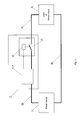
- fig. 1 shows schematically the protective system with a circuit breaker incorporating the release mechanism according to the present invention
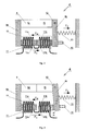
- fig. 2 the release mechanism in closed state in the first embodiment of the invention
- fig. 3 the release mechanism in open state in the first embodiment of the invention
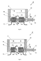
- fig. 4 the release mechanism in closed state in the second embodiment of the invention
- fig. 5 the release mechanism in open state in the second embodiment of the invention.
- the protective system comprises a power source 1, a circuit breaker 2 and a protected energy receiver 6.
- the power source 1 is connected with the circuit breaker 2 through a conductor 3a and a release mechanism 4, 4'.
- the circuit breaker 2 is electrically connected with the protected receiver 6 through a conductor 3b.
- the receiver 6 is connected with the power source 1 through a conductor 3c.
- the power source 1, the conductor 3a, the release mechanism 4,4', the circuit breaker 2, the conductor 3b, the receiver 6 and the conductor 3c together form a closed electric circuit.
- the release mechanism 4, 4' is built in the form of a magnetic circuit.
- the circuit breaker 2 is connected with a drive element 5 preferably mechanically connected with the release mechanism 4, 4' and it is electrically connected with the protected receiver 6.
- the circuit breaker 2, the drive element 5 and the release mechanism 4,4' can be located in a common housing 7.
- the release mechanism 4,4' contains a permanent magnet 8 whose poles are connected with elements made of a magnetically soft material which form the yokes of the magnetic circuit of the release mechanism, the first immovable yoke 9a being permanently connected with the first pole of the permanent magnet 8 and the second movable yoke 9b being rotationally connected with the second pole of the permanent magnet 8, as in the first embodiment of the invention, or the first immovable yoke 9a being permanently connected with the first pole of the permanent magnet 8, and the second immovable yoke 9b' being permanently connected with the second pole of the permanent magnet 8, as in the second embodiment of the invention.
- the yokes 9a, 9b and 9b' have the form of plates made of a magnetically soft material which are situated opposite one another. Between the yokes 9a and 9b, or 9a and 9b' there is located the armature of the magnetic circuit of the release mechanism 4,4', which is an electromagnet 10 formed by two cores 10a and 10b, in the first embodiment of the invention, or 10a and 10b' in the second embodiment of the invention. Electric coils 11a and 11b which are electrically connected with the circuit breaker 2 and with the power source 1 through the conductor 3a are wound in directions opposite to one another on the cores 10a and 10b, or on the cores 10a and 10b'.
- the coil 11a is wound directly on the core 10a or it is fixed by means of a thermally conductive cement or a thermally conductive paste, which is not shown in the drawing.
- the coil 11b is wound on the core 10b or 10b' in such way that the core can freely move inside the coil and the winding direction of the coil 11b is opposite to the winding direction of the coil 11a.
- the cores 10a, 10b, 10b' of the electromagnet are made of a magnetically soft ferromagnetic material which after exceeding the Curie temperature T c , changes its characteristics from ferromagnetic to paramagnetic.
- the electromagnet cores 10a, 10b, 10b' behave as ferromagnetics and they present a convenient path for the magnetic flux generated by the permanent magnet 8, i.e. they have low magnetic reluctance.
- the electromagnet core 10a, 10b, 10b' increases its magnetic reluctance and breaks the path for the magnetic flux generated by the permanent magnet 8.
- the cores 10a, 10b, 10b' of the electromagnet 10 are made of a ferromagnetic material whose Curie temperature T c is within the range from 60°C to 150°C. The following materials have such properties:
- the immovable yoke 9a is permanently fixed to one of the poles of the permanent magnet 8.
- the movable yoke 9b is fixed to the other pole of the permanent magnet 8 by means of a pivot 12 in such way that the yoke 9b can rotate within a limited range around the axis of rotation of the pivot 12 without losing contact with the permanent magnet 8.
- the magnetic cores 10a and 10b are permanently attached to the free ends of the yokes 9a and 9b in such way that in the closed state of the release mechanism 4 the free ends of the cores contact each other frontally.
- the cores 10a and 10b there are electric coils 11a and 11b wound in directions opposite to one another, preferably of copper wire, which are electrically connected with the conductor 3a and the circuit breaker 2.
- the coils 11a, 11b are used to generate a magnetic field in the cores 10a and 10b.
- the direction of winding opposite to one another of the electric coils 11a and 11b means that the coil 11a on the magnetic core 10a is wound in one direction, and the coil 11b on the magnetic core 10b is wound in the opposite direction, and owing to that the coil 11a magnetizes the core 10a with the opposite magnetic polarization to the magnetic polarization of the core 10b magnetized by the coil 11b.
- Oppositely magnetized cores will repel each other and the repulsion force will depend on the value of the current flowing through the coils 11a and 11b.
- the permanent magnet 8, the yokes 9a, 9b of a magnetically soft material and the cores 10a, 10b form a magnetic circuit which is closed when the cores 10a and 10b contact each other, i.e. in the closed state of the release mechanism 4.
- Magnetic cores 10a and 10b can contact one another or disconnect, depending on the change in the position of the movable yoke 9b of the magnetic circuit that forms the magnetic path for the magnetic flux generated by the permanent magnet 8.
- the magnetic flux whose source is the permanent magnet 8 generates such force of magnetic attraction that makes the core 10b of the movable yoke 9b attracted and frontally contacts the core 10a of the immovable yoke 9a of the magnetic circuit.
- the tension force of the spring 13 attached to the movable yoke 9b counteracts the force of magnetic attraction generated by the permanent magnet 8.
- the repulsion force generated by the cores 10a and 10b counteracts the force of magnetic attraction.
- the magnetic circuit remains closed, i.e. it remains in the closed state of the release mechanism 4 - fig. 2 .
- the principle of operation of the release mechanism 4 according to the first embodiment of the invention depends on the type of the factor causing the action of the release mechanism and it is different in the case of occurrence of a short circuit and in the case of occurrence of an overload in the system protected by the circuit breaker.
- the release mechanism 4 operates in the following way.
- the coil 11a When short-circuit current flows through the coils 11a and 11b, the coil 11a generates a magnetic field in the first core 10a of the electromagnet and the coil 11b generates a magnetic field in the other core 10b of the electromagnet.
- the magnetic fields generated in both cores 10a and 10b generated as a result of flow of the same current, will also be directed in directions opposite to each other.
- the oppositely directed magnetic fields in both cores will repel each other creating a force of repulsion of magnetic fields, in the drawing indicated by the arrow F c .
- the load current flows through the electric coils 11a and 11b which are made of a conductor, e.g. copper wire, of a specific resistance. Flow of load current through the coils 11a and 11b results in loss of power dissipated in the form of heat.
- the amount of emitted heat depends on the strength of the load current of the receiver 6. An increase in the strength of the current increases the amount of emitted heat which affects the increase in the temperature of the coils 11a and 11b. Since the coils 11a and 11b are wound on the cores 10a and 10b, these cores 10a and 10b heat up from them. A load current larger than the rated current will heat up the cores 10a, 10b stronger.
- the cores 10a, 10b will pass from ferromagnetic state to paramagnetic state, increasing the reluctance of the magnetic circuit through which the magnetic flux generated by the permanent magnet 8 closes. In consequence, the magnetic flux generated by the permanent magnet 8 decreases and the force of magnetic attraction of the cores 10a and 10b, indicated in the drawing by the arrow F M , decreases. If the force F M is less than the tension force of the spring 13, indicated in the drawing by the arrow F s , then the movable yoke 9b together with the core 10b and the push rod 15 will turn around the axis of rotation of the pivot 12 by an angle ⁇ - fig. 3 . The turn of the yoke 9b and the change in the position of the push rod 15 actuates the drive 5 of the circuit breaker 2.
- the immovable yoke 9a made of a magnetically soft material, whose other end is permanently connected with the core 10a, is permanently connected to one pole of the permanent magnet 8.
- the other pole of the permanent magnet 8 is permanently connected with the second immovable yoke 9b'.
- the yoke 9b' there is an opening 14 through which the movable core 10b' moves.
- Magnetic flux whose source is the permanent magnet 8, generates such force of magnetic attraction that the movable core 10b' of the immovable yoke 9b' is attracted and frontally contacts the immovable core 10a of the yoke 9a of the magnetic circuit. In such case a closed magnetic circuit is formed for the flux generated by the permanent magnet 8.
- the core 10b' has a mechanical element 15 attached to it, in the form of a push rod or a pull rod on which a expanding spring 16 is located. With its one end the expanding spring rests on the external surface of the yoke 9b', and the other end rests on a resistance element 17 fixed to the other end of the push rod 15.
- the mechanical element 15 transfers the expansion force of the spring 16 which attempts to move the core 10b' towards the opening 14 in the yoke 9b' and break the magnetic circuit of the magnetic flux generated by the permanent magnet 8. If the expansion force of the spring 16 is smaller than the force of magnetic attraction caused by the permanent magnet 8, the magnetic circuit remains closed, i.e. in the closed state of the release mechanism 4' - fig. 4 .
- the principle of operation of the release mechanism 4' according to the second embodiment of the invention depends on the type of the factor causing the action of the release mechanism and it is different in the case of occurrence of a short circuit and in the case of occurrence of an overload in the system protected by the circuit breaker.
- the coil 11a When short-circuit current flows through the coils 11a and 11b, the coil 11a generates a magnetic field in the first core 10a of the electromagnet and the coil 11b generates a magnetic field in the other core 10b' of the electromagnet.
- the magnetic fields generated in both cores 10a and 10b' generated as a result of flow of the same current, will also be directed in directions opposite to each other.
- the oppositely directed magnetic fields in both cores will repel each other creating a force of repulsion of magnetic fields, in the drawing indicated by the arrow F c .
- both cores 10a and 10b' If the force F c in both cores 10a and 10b' is larger than the force of magnetic attraction generated by the permanent magnet 8, in the drawing indicated by the arrow F M , and reduced by the expansion force of the spring 16, in the drawing indicated by the arrow F s , the cores 10a and 10b' will repel each other, and the movable core 10b' will move by a distance x indicated in the drawing, towards the opening 14 at the same time moving the push rod 15 outside the release mechanism 4' - fig. 5 . The shift of the push rod 15 by the distance x activates the drive 5 of the circuit breaker 2.
- the load current flows through the electric coils 11a and 11b, which are made of a conductor, e.g. copper wire, of a specific resistance. Flow of load current through the coils 11a and 11b results in loss of power dissipated in the form of heat.
- the amount of emitted heat depends on the strength of the load current of the receiver 6. An increase in the current strength increases the amount of emitted heat which affects the increase in the temperature of the coils 11a and 11b. Since the coils 11a and 11b are wound on the cores 10a and 10b', the cores 10a and 10b' heat up from them. A load current larger than the rated current will heat up the cores 10a, 10b stronger.
- the cores 10a, 10b' will pass from ferromagnetic state to paramagnetic state, increasing the reluctance of the magnetic circuit through which the magnetic flux generated by the permanent magnet 8 closes. In consequence, the magnetic flux generated by the permanent magnet 8 decreases and the force of magnetic attraction of the cores 10a and 10b', indicated in the drawing by the arrow F M , decreases. If the force F M is less than the expansion force of the spring 16, indicated in the drawing by the arrow F s , the movable core 10b' will move by a distance x in the drawing, towards the opening 14, at the same time moving the push rod 15 outside the release mechanism 4' - fig. 5 . The shift of the push rod 15 by the distance x actuates the drive 5 of the circuit breaker 2.
- the yokes 9a, 9b and 9b' may take a different shape than that described in the example of the invention embodiment.
- the yokes 9a, 9b and 9b' can be a part of the permanent magnet 8, i.e. its poles, or they can form suitably shaped magnetic cores of the electromagnet 10.
- Individual coils 11a, 11b wound on the cores 10a, 10b and 10b' can have different number of turns depending on the operating needs of the release mechanism 4, 4'.
Landscapes
- Physics & Mathematics (AREA)
- Electromagnetism (AREA)
- Electromagnets (AREA)
- Breakers (AREA)
Abstract
Description
- The invention relates to a thermo-magnetic release mechanism for circuit breakers protecting electric circuits in electric transmission networks, and in particular for circuit breakers protecting the electric circuits of electric energy receivers against short circuits or overloads.
- There are commonly known devices for releasing a circuit breaker which protects an electric circuit, in which two independent mechanisms are used. One is an electromagnetic release which reacts to the occurrence of short circuit current, i.e. a current of a value many times exceeding the value of the rated current of the protected device. The other is a thermobimetal element which reacts to the occurrence of overload current , i.e. a slowly growing current of a value exceeding the value of the rated current of the protected device by not more than a few dozen percent.
- Patent description
EP1526560 describes a circuit breaker comprising an electromagnetic release and a thermal release which are located in a common housing. The main current path of the circuit breaker contains the contacts of the main circuit breaker, an electromagnetic release and a thermal release. The electromagnetic release is the main current coil placed on a magnetic core. If a short circuit current flows through the coil winding in the main path, the electromagnetic release causes the opening of the contacts of the main circuit breaker. If an overload current occurs, the thermal release located in the auxiliary current path activates an additional disconnecting mechanism which opens the contacts of the main circuit breaker. The thermal release is an electromagnetic circuit comprising a magnetic core, an auxiliary current coil placed on the core yoke, a magnetic armature and a thermobimetal element or a permanent magnet made of a material with variable magnetic permeability. The current coil heats up the thermobimetal element or the permanent magnet which after reaching a suitable temperature cause the movement of the magnetic armature which closes the magnetic circuit of the thermal release and activates the additional disconnecting mechanism for the contacts of the main circuit breaker. The presented solution includes two independent mechanisms for releasing the circuit breaker, which complicates the design of the release and lengthens the current path of the circuit breaker. - The essence of the thermo-magnetic release mechanism for an electric power circuit breaker, comprising an electric circuit and a magnetic circuit, both mechanically and electrically connected with the drive mechanism of the circuit breaker, in which the magnetic circuit comprises a permanent magnet and elements made of a magnetically soft material connected to its poles, which elements are the yokes of the circuit between which the magnetic circuit armature is located, the armature is an electromagnet made of two separable cores, one immovable and one movable, individually connected with the respective pair of yokes and contacting each other frontally in the closed state of the release mechanism. The cores are made of a ferromagnetic material which when heated above the Curie temperature (Tc) changes its characteristics from ferromagnetic to paramagnetic. The coils of the electromagnet are wound in directions opposite to one another on the separable elements of the core with respect to the two separable elements.
- Preferably, the movable core of the electromagnet is permanently connected with the yoke of the magnetic circuit fixed by pivot to the pole of the permanent magnet.
- Preferably, a tension spring of a tension force smaller than the attractive force between the elements of the electromagnet core, which is generated by the permanent magnet, is fixed to the yoke fixed by pivot to a pole of the permanent magnet.
- Alternatively, the movable core of the electromagnet is slidably connected with the yoke of the magnetic circuit, which is permanently fixed to the pole of a permanent magnet, and it is permanently connected with one end of a push rod situated in the yoke opening and protruding outside the external surface of the yoke.
- Preferably, on the push rod that protrudes outside the external surface of the yoke there is located a tension spring whose one end rests on the external surface of the yoke and the other end rests on a resistance element fixed to the other end of the push rod. The expanding force of the tension spring is smaller than the attractive force between the cores of the electromagnet, generated by the permanent magnet.
- Preferably, the core of the electromagnet is made of a material whose Curie temperature Tc ranges from 60 to 150°C.
- Preferably, the core of the electromagnet is made of ferro powders or sinters of magnetically soft materials, super-paramagnetic materials in the form of: powders, sinters, suspensions or other forms of ferromagnetic particles in nanometric or micrometric sizes, gadolinium-based alloys or composites, Perovskite structures.
- Preferably, the numbers of turns of the coils (11a, 11b) is different.
- Preferably, the electromagnet coil located on the immovable core is connected with that core by means of a thermally conducting paste or cement.
- The advantage of the thermo-magnetic release mechanism according to the invention is its simple design permitting substitution of two independent release mechanisms with one mechanism which reacts both to a short circuit and to an overload of the protected circuit. This results in simplification of the current path in the protective circuit breaker. The release mechanism is applicable to circuit breakers which require small dimensions of the release mechanism and simplification of the current path enclosed in the circuit breaker that protects an electric circuit.
- The subject of the invention is presented as an embodiment in the drawings wherein
fig. 1 shows schematically the protective system with a circuit breaker incorporating the release mechanism according to the present invention,fig. 2 - the release mechanism in closed state in the first embodiment of the invention,fig. 3 - the release mechanism in open state in the first embodiment of the invention,fig. 4 - the release mechanism in closed state in the second embodiment of the invention,fig. 5 -the release mechanism in open state in the second embodiment of the invention. - The protective system comprises a power source 1, a
circuit breaker 2 and a protectedenergy receiver 6. The power source 1 is connected with thecircuit breaker 2 through aconductor 3a and arelease mechanism 4, 4'. Thecircuit breaker 2 is electrically connected with theprotected receiver 6 through aconductor 3b. Thereceiver 6 is connected with the power source 1 through aconductor 3c. The power source 1, theconductor 3a, therelease mechanism 4,4', thecircuit breaker 2, theconductor 3b, thereceiver 6 and theconductor 3c together form a closed electric circuit. Therelease mechanism 4, 4' is built in the form of a magnetic circuit. Thecircuit breaker 2 is connected with adrive element 5 preferably mechanically connected with therelease mechanism 4, 4' and it is electrically connected with theprotected receiver 6. Thecircuit breaker 2, thedrive element 5 and therelease mechanism 4,4' can be located in acommon housing 7. - The
release mechanism 4,4' contains apermanent magnet 8 whose poles are connected with elements made of a magnetically soft material which form the yokes of the magnetic circuit of the release mechanism, the firstimmovable yoke 9a being permanently connected with the first pole of thepermanent magnet 8 and the secondmovable yoke 9b being rotationally connected with the second pole of thepermanent magnet 8, as in the first embodiment of the invention, or the firstimmovable yoke 9a being permanently connected with the first pole of thepermanent magnet 8, and the secondimmovable yoke 9b' being permanently connected with the second pole of thepermanent magnet 8, as in the second embodiment of the invention. Theyokes yokes release mechanism 4,4', which is anelectromagnet 10 formed by twocores Electric coils circuit breaker 2 and with the power source 1 through theconductor 3a are wound in directions opposite to one another on thecores cores coil 11a is wound directly on thecore 10a or it is fixed by means of a thermally conductive cement or a thermally conductive paste, which is not shown in the drawing. Thecoil 11b is wound on thecore coil 11b is opposite to the winding direction of thecoil 11a. Thecores electromagnet cores permanent magnet 8, i.e. they have low magnetic reluctance. When the Curie temperature Tc is exceeded, theelectromagnet core permanent magnet 8. In therelease mechanism 4, 4' thecores electromagnet 10 are made of a ferromagnetic material whose Curie temperature Tc is within the range from 60°C to 150°C. The following materials have such properties: - ferro powders or sintered magnetically soft materials i.e. iron oxide, magnesium, nickel and zinc, for which the Curie temperature Tc is higher than 60°C and lower than 150°C,
- super-paramagnetics, i.e. powders, sintered materials, suspensions or other forms of ferromagnetic iron, cobalt, chromium , nickel, gadolinium in a nanometric or micrometric sizes, showing the effect of passing from ferromagnetic to paramagnetic state at Curie temperature Tc is higher than 60°C and lower than 150°C,
- gadolinium-based alloys or composites,
- Perovskite structures, for example ferromagnetic ceramics i.e. barium titanate of a Curie temperature Tc of approximately 120°C.
- In the first embodiment of the invention the
immovable yoke 9a is permanently fixed to one of the poles of thepermanent magnet 8. Themovable yoke 9b is fixed to the other pole of thepermanent magnet 8 by means of apivot 12 in such way that theyoke 9b can rotate within a limited range around the axis of rotation of thepivot 12 without losing contact with thepermanent magnet 8. Themagnetic cores yokes release mechanism 4 the free ends of the cores contact each other frontally. On thecores electric coils conductor 3a and thecircuit breaker 2. Thecoils cores electric coils coil 11a on themagnetic core 10a is wound in one direction, and thecoil 11b on themagnetic core 10b is wound in the opposite direction, and owing to that thecoil 11a magnetizes thecore 10a with the opposite magnetic polarization to the magnetic polarization of thecore 10b magnetized by thecoil 11b. Oppositely magnetized cores will repel each other and the repulsion force will depend on the value of the current flowing through thecoils permanent magnet 8, theyokes cores cores release mechanism 4. To themovable yoke 9b there is fixed atension spring 13, one of its ends being permanently connected to the circuit breaker housing, which is not shown in the drawing.Magnetic cores movable yoke 9b of the magnetic circuit that forms the magnetic path for the magnetic flux generated by thepermanent magnet 8. The magnetic flux whose source is thepermanent magnet 8 generates such force of magnetic attraction that makes thecore 10b of themovable yoke 9b attracted and frontally contacts thecore 10a of theimmovable yoke 9a of the magnetic circuit. The tension force of thespring 13 attached to themovable yoke 9b counteracts the force of magnetic attraction generated by thepermanent magnet 8. Also the repulsion force generated by thecores spring 13 compare to the mutual repulsion of thecores permanent magnet 8, then the magnetic circuit remains closed, i.e. it remains in the closed state of the release mechanism 4 -fig. 2 . - The principle of operation of the
release mechanism 4 according to the first embodiment of the invention depends on the type of the factor causing the action of the release mechanism and it is different in the case of occurrence of a short circuit and in the case of occurrence of an overload in the system protected by the circuit breaker. - In the case of a short circuit the
release mechanism 4 operates in the following way. - When short-circuit current flows through the
coils coil 11a generates a magnetic field in thefirst core 10a of the electromagnet and thecoil 11b generates a magnetic field in theother core 10b of the electromagnet. As both parts of the coils are wound in directions opposite to one another, the magnetic fields generated in bothcores cores permanent magnet 8, in the drawing indicated by the arrow FM, and reduced by the tension force of thespring 13, in the drawing indicated by the arrow Fs, then thecores movable yoke 9b together with the core 10b and thepush rod 15 will turn around the axis of rotation of thepivot 12 by an angle α -fig. 3 . The rotation of theyoke 9b and the change in the position of thepush rod 15 activates thedrive 5 of thecircuit breaker 2. - The load current flows through the
electric coils coils receiver 6. An increase in the strength of the current increases the amount of emitted heat which affects the increase in the temperature of thecoils coils cores cores cores cores cores permanent magnet 8 closes. In consequence, the magnetic flux generated by thepermanent magnet 8 decreases and the force of magnetic attraction of thecores spring 13, indicated in the drawing by the arrow Fs, then themovable yoke 9b together with the core 10b and thepush rod 15 will turn around the axis of rotation of thepivot 12 by an angle α-fig. 3 . The turn of theyoke 9b and the change in the position of thepush rod 15 actuates thedrive 5 of thecircuit breaker 2. - In the second embodiment of the invention, the
immovable yoke 9a, made of a magnetically soft material, whose other end is permanently connected with thecore 10a, is permanently connected to one pole of thepermanent magnet 8. The other pole of thepermanent magnet 8 is permanently connected with the secondimmovable yoke 9b'. In theyoke 9b' there is anopening 14 through which themovable core 10b' moves. Magnetic flux, whose source is thepermanent magnet 8, generates such force of magnetic attraction that themovable core 10b' of theimmovable yoke 9b' is attracted and frontally contacts theimmovable core 10a of theyoke 9a of the magnetic circuit. In such case a closed magnetic circuit is formed for the flux generated by thepermanent magnet 8. The core 10b' has amechanical element 15 attached to it, in the form of a push rod or a pull rod on which a expandingspring 16 is located. With its one end the expanding spring rests on the external surface of theyoke 9b', and the other end rests on aresistance element 17 fixed to the other end of thepush rod 15. Themechanical element 15 transfers the expansion force of thespring 16 which attempts to move the core 10b' towards the opening 14 in theyoke 9b' and break the magnetic circuit of the magnetic flux generated by thepermanent magnet 8. If the expansion force of thespring 16 is smaller than the force of magnetic attraction caused by thepermanent magnet 8, the magnetic circuit remains closed, i.e. in the closed state of the release mechanism 4' -fig. 4 . - The principle of operation of the release mechanism 4' according to the second embodiment of the invention depends on the type of the factor causing the action of the release mechanism and it is different in the case of occurrence of a short circuit and in the case of occurrence of an overload in the system protected by the circuit breaker.
- In the case of a short circuit the release mechanism 4' operates in the following way.
- When short-circuit current flows through the
coils coil 11a generates a magnetic field in thefirst core 10a of the electromagnet and thecoil 11b generates a magnetic field in theother core 10b' of the electromagnet. As both parts of the coils are wound in directions opposite to each other, the magnetic fields generated in bothcores cores permanent magnet 8, in the drawing indicated by the arrow FM, and reduced by the expansion force of thespring 16, in the drawing indicated by the arrow Fs, thecores movable core 10b' will move by a distance x indicated in the drawing, towards the opening 14 at the same time moving thepush rod 15 outside the release mechanism 4' -fig. 5 . The shift of thepush rod 15 by the distance x activates thedrive 5 of thecircuit breaker 2. - The load current flows through the
electric coils coils receiver 6. An increase in the current strength increases the amount of emitted heat which affects the increase in the temperature of thecoils coils cores cores cores cores cores permanent magnet 8 closes. In consequence, the magnetic flux generated by thepermanent magnet 8 decreases and the force of magnetic attraction of thecores spring 16, indicated in the drawing by the arrow Fs, themovable core 10b' will move by a distance x in the drawing, towards the opening 14, at the same time moving thepush rod 15 outside the release mechanism 4' -fig. 5 . The shift of thepush rod 15 by the distance x actuates thedrive 5 of thecircuit breaker 2. - For both embodiments, the
yokes yokes permanent magnet 8, i.e. its poles, or they can form suitably shaped magnetic cores of theelectromagnet 10.Individual coils cores release mechanism 4, 4'. - Key to the drawings
- 1 - power source
- 2 - circuit breaker
- 3a, 3b, 3c - electric conductors
- 4, 4' - release mechanism
- 5 - circuit breaker drive
- 6 - energy receiver - load
- 7 - circuit breaker housing
- 8 - permanent magnet
- 9a, 9b' - immovable yoke of the magnetic circuit
- 9b - movable yoke of the magnetic circuit
- 10 - electromagnet
- 10a - immovable core of electromagnet
- 10b, 10b' - movable cores of the electromagnet
- 11a, 11b - electromagnet coils
- 12 - pivot
- 13 - tension spring
- 14 - opening in
yoke 9b' - 15 - mechanical element - push rod
- 16 - expanding spring
- 17 - resistance element
- FC - force of repulsion of magnetic fields
- FM - force of attraction of magnetic cores
- FS - tension or expansion force of spring
Claims (9)
- A thermo-magnetic release mechanism (4,4') for an electric power circuit breaker (2), comprising an electric circuit and a magnetic circuit, both mechanically and electrically connected with the drive mechanism (5) of the circuit breaker, in which the magnetic circuit comprises a permanent magnet (8) and elements of a magnetically soft material connected to its poles, which elements form the yokes (9a,9b) or (9a,9b') of the circuit, between which the armature of the magnetic circuit is located, characterized in that the armature is an electromagnet (10) which is made of two separable cores, one immovable (10a) and one movable (10b) or (10b'), individually connected with the respective pair of yokes (9a, 9b) or (9a, 9b') and contacting each other frontally in the closed state of the release mechanism (4,4'), and it is made of a ferromagnetic material which when heated above the Curie temperature (Tc) changes its ferromagnetic characteristics to paramagnetic characteristics, and the coils (11a, 11b) of the electromagnet (10) are wound on the separable elements of the core (10a, 10b or 10b') in directions opposite to one another with respect to the two separable elements.
- A release mechanism according to claim 1, characterized in that the movable core (10b) of the electromagnet (10) is permanently connected with the yoke (9b) of the magnetic circuit, fixed by pivot to the pole of the permanent magnet (8).
- A release mechanism according to claim 2, characterized in that a tension spring (13) having a tension force (FS) smaller than the force of magnetic attraction (FM) between the elements of the core (10a, 10b) of the electromagnet, generated by the permanent magnet (8), is attached to the yoke (9b) of the magnetic circuit.
- A release mechanism according to claim 1, characterized in that the movable core (10b') of the electromagnet (10) is slidably connected with the yoke (9b') of the magnetic circuit, permanently fixed to the pole of the permanent magnet (8) and it is permanently connected with one end of a push rod (15) situated in the opening (14) of the yoke (9b') and protruding outside the external surface of the yoke (9b').
- A release mechanism according to claim 4, characterized in that on the push rod (15) there is located an expanding spring (16) whose one end rests on the external surface of the yoke (9b') and the other end rests on a resistance element (17) fixed to the other end of the push rod (15), the expansion force (FS) of the expanding spring (16) being smaller than the force of magnetic attraction (FM) between the cores (10a, 10b') of the electromagnet (10), generated by the permanent magnet (8).
- A release mechanism according to any of the claims 1-5, characterized in that the core (10a, 10b, 10b') is made of a material whose Curie temperature TC is in the range from 60 to 150°C.
- A release mechanism according to any of the claims 1-6, characterized in that the core of the electromagnet (10) is made of ferro powders or sinters of magnetically soft materials, super-paramagnetic materials in the form of: powders, sinters, suspensions or other forms of ferromagnetic particles in nanometric or micrometric sizes, gadolinium-based alloys or composites, Perovskite structures.
- A release mechanism according to any of the claims 1-6, characterized in that the numbers of turns of the coils (11a, 11b) are different.
- A release mechanism according to any of the claims 1-6, characterized in that the coil (11a) is connected with the core of the electromagnet (10a) by means of a thermally conducting paste or cement.
Priority Applications (5)
| Application Number | Priority Date | Filing Date | Title |
|---|---|---|---|
| EP20110460056 EP2595169B1 (en) | 2011-11-21 | 2011-11-21 | Thermo-magnetic release mechanism for circuit breakers |
| ES11460056T ES2467937T3 (en) | 2011-11-21 | 2011-11-21 | Thermo-magnetic trip mechanism for switches |
| CN201280055166.2A CN104054154B (en) | 2011-11-21 | 2012-10-10 | Thermal Magnetic Release Mechanism for Circuit Breakers |
| PCT/EP2012/004238 WO2013075770A1 (en) | 2011-11-21 | 2012-10-10 | Thermo-magnetic release mechanism for circuit breakers |
| IN4229CHN2014 IN2014CN04229A (en) | 2011-11-21 | 2012-10-10 |
Applications Claiming Priority (1)
| Application Number | Priority Date | Filing Date | Title |
|---|---|---|---|
| EP20110460056 EP2595169B1 (en) | 2011-11-21 | 2011-11-21 | Thermo-magnetic release mechanism for circuit breakers |
Publications (2)
| Publication Number | Publication Date |
|---|---|
| EP2595169A1 true EP2595169A1 (en) | 2013-05-22 |
| EP2595169B1 EP2595169B1 (en) | 2014-03-19 |
Family
ID=47115723
Family Applications (1)
| Application Number | Title | Priority Date | Filing Date |
|---|---|---|---|
| EP20110460056 Active EP2595169B1 (en) | 2011-11-21 | 2011-11-21 | Thermo-magnetic release mechanism for circuit breakers |
Country Status (5)
| Country | Link |
|---|---|
| EP (1) | EP2595169B1 (en) |
| CN (1) | CN104054154B (en) |
| ES (1) | ES2467937T3 (en) |
| IN (1) | IN2014CN04229A (en) |
| WO (1) | WO2013075770A1 (en) |
Cited By (1)
| Publication number | Priority date | Publication date | Assignee | Title |
|---|---|---|---|---|
| US11422202B2 (en) * | 2020-08-11 | 2022-08-23 | Siemens Industry, Inc. | Overload current detection in a circuit interrupting device |
Families Citing this family (3)
| Publication number | Priority date | Publication date | Assignee | Title |
|---|---|---|---|---|
| CN105762036B (en) * | 2016-03-29 | 2017-10-20 | 东南大学 | One kind is based on the self-triggering modularization multi-level converter DC side breaker of vortex |
| CN112382547B (en) * | 2020-11-05 | 2023-10-17 | 美高电气科技有限公司 | Thermomagnetic adjustable release |
| CN114430096B (en) * | 2021-12-27 | 2023-06-30 | 盐城工学院 | Battery structure of new energy automobile |
Citations (4)
| Publication number | Priority date | Publication date | Assignee | Title |
|---|---|---|---|---|
| WO2002043095A1 (en) * | 2000-11-23 | 2002-05-30 | Abb Patent Gmbh | Electrical breaker device for current leakage, current overload and short-circuit protection |
| DE10220665A1 (en) * | 2002-05-10 | 2003-11-20 | Abb Patent Gmbh | Switch for protecting an electric motor has a contact point with fixed and movable contact pieces and a switch latch to act on the contact point. |
| DE10222552A1 (en) * | 2000-11-23 | 2003-11-27 | Abb Patent Gmbh | Electrical trip switch mechanism comprises permanent magnets set into a coil former that respond to overload or short circuit current |
| EP1526560A2 (en) | 2003-10-25 | 2005-04-27 | ABB PATENT GmbH | Electric circuit breaker |
Family Cites Families (5)
| Publication number | Priority date | Publication date | Assignee | Title |
|---|---|---|---|---|
| EP0143022B1 (en) * | 1983-10-21 | 1988-06-01 | Merlin Gerin | Thermal and magnetic circuit breaker tripping mechanism |
| CN2141931Y (en) * | 1992-10-29 | 1993-09-08 | 江门市泰来电子仪器厂 | Magnetic-thermal timing switch |
| CN2437041Y (en) * | 2000-05-19 | 2001-06-27 | 陈德阳 | Circuit breaker |
| WO2003098651A1 (en) * | 2002-05-17 | 2003-11-27 | Abb Patent Gmbh | Breaker unit for fault current, excess current and short-circuit current protection |
| JP2007234250A (en) * | 2006-02-27 | 2007-09-13 | Fuji Electric Fa Components & Systems Co Ltd | Circuit breaker trip device |
-
2011
- 2011-11-21 ES ES11460056T patent/ES2467937T3/en active Active
- 2011-11-21 EP EP20110460056 patent/EP2595169B1/en active Active
-
2012
- 2012-10-10 IN IN4229CHN2014 patent/IN2014CN04229A/en unknown
- 2012-10-10 WO PCT/EP2012/004238 patent/WO2013075770A1/en not_active Ceased
- 2012-10-10 CN CN201280055166.2A patent/CN104054154B/en active Active
Patent Citations (4)
| Publication number | Priority date | Publication date | Assignee | Title |
|---|---|---|---|---|
| WO2002043095A1 (en) * | 2000-11-23 | 2002-05-30 | Abb Patent Gmbh | Electrical breaker device for current leakage, current overload and short-circuit protection |
| DE10222552A1 (en) * | 2000-11-23 | 2003-11-27 | Abb Patent Gmbh | Electrical trip switch mechanism comprises permanent magnets set into a coil former that respond to overload or short circuit current |
| DE10220665A1 (en) * | 2002-05-10 | 2003-11-20 | Abb Patent Gmbh | Switch for protecting an electric motor has a contact point with fixed and movable contact pieces and a switch latch to act on the contact point. |
| EP1526560A2 (en) | 2003-10-25 | 2005-04-27 | ABB PATENT GmbH | Electric circuit breaker |
Cited By (1)
| Publication number | Priority date | Publication date | Assignee | Title |
|---|---|---|---|---|
| US11422202B2 (en) * | 2020-08-11 | 2022-08-23 | Siemens Industry, Inc. | Overload current detection in a circuit interrupting device |
Also Published As
| Publication number | Publication date |
|---|---|
| EP2595169B1 (en) | 2014-03-19 |
| CN104054154A (en) | 2014-09-17 |
| WO2013075770A1 (en) | 2013-05-30 |
| CN104054154B (en) | 2016-03-09 |
| ES2467937T3 (en) | 2014-06-13 |
| IN2014CN04229A (en) | 2015-07-17 |
Similar Documents
| Publication | Publication Date | Title |
|---|---|---|
| US7088207B2 (en) | Electrical switching device for fault-current, overcurrent and short-circuit current position | |
| US20080284547A1 (en) | Magnetostrictive electrical switching device | |
| EP2595169B1 (en) | Thermo-magnetic release mechanism for circuit breakers | |
| CN110651352B (en) | Overcurrent protection device | |
| WO2008139533A1 (en) | Electronic overload relay | |
| CN102024630A (en) | Electromagnetic release | |
| CN201387783Y (en) | Magnetic latching electromagnet device | |
| EP2254140B1 (en) | Thermally independent overcurrent tripping device | |
| CN104364870B (en) | Electrical switching devices and relays comprising ferromagnets or magnetic armatures with tapered sections | |
| US9355803B2 (en) | Actuator with thermomagnetic shunt, especially for triggering a circuit breaker | |
| US20080258850A1 (en) | Switching Device Having an Electromagnetic Release | |
| CN115699236A (en) | Switching system | |
| US10283301B2 (en) | Electromagnetic actuator and circuit breaker comprising such an actuator | |
| US20240339278A1 (en) | Overcurrent protection device based on thermo magnetically-shiftable material | |
| EP4583143A1 (en) | Magnetic latching trip actuator and switching appliance | |
| CN111446136A (en) | Instantaneous tripping mechanism of miniature circuit breaker based on parallel shunt | |
| JP7413975B2 (en) | Overcurrent switch and electronic circuit breaker equipped with this overcurrent switch | |
| JP7127545B2 (en) | electromagnetic actuator | |
| US11501940B2 (en) | Electromagnetic actuator and electrical switching unit including this actuator | |
| CN109215934A (en) | Magnetictrip for electromagnetic switchgear | |
| JPH0528900A (en) | Circuit breaker | |
| EP1906427A1 (en) | An electromagnetic drive unit and an electromechanical switching device | |
| RU41545U1 (en) | AUTOMATIC FAST SWITCH | |
| CN121641774A (en) | Static contact and electromagnetic release of electric switch | |
| JPH0594756A (en) | Circuit breaker |
Legal Events
| Date | Code | Title | Description |
|---|---|---|---|
| PUAI | Public reference made under article 153(3) epc to a published international application that has entered the european phase |
Free format text: ORIGINAL CODE: 0009012 |
|
| AK | Designated contracting states |
Kind code of ref document: A1 Designated state(s): AL AT BE BG CH CY CZ DE DK EE ES FI FR GB GR HR HU IE IS IT LI LT LU LV MC MK MT NL NO PL PT RO RS SE SI SK SM TR |
|
| AX | Request for extension of the european patent |
Extension state: BA ME |
|
| 17P | Request for examination filed |
Effective date: 20130621 |
|
| RBV | Designated contracting states (corrected) |
Designated state(s): AL AT BE BG CH CY CZ DE DK EE ES FI FR GB GR HR HU IE IS IT LI LT LU LV MC MK MT NL NO PL PT RO RS SE SI SK SM TR |
|
| GRAP | Despatch of communication of intention to grant a patent |
Free format text: ORIGINAL CODE: EPIDOSNIGR1 |
|
| INTG | Intention to grant announced |
Effective date: 20140108 |
|
| GRAS | Grant fee paid |
Free format text: ORIGINAL CODE: EPIDOSNIGR3 |
|
| GRAA | (expected) grant |
Free format text: ORIGINAL CODE: 0009210 |
|
| RIN1 | Information on inventor provided before grant (corrected) |
Inventor name: MROZEK, ADRIAN Inventor name: RUSZCZYK, ADAM |
|
| AK | Designated contracting states |
Kind code of ref document: B1 Designated state(s): AL AT BE BG CH CY CZ DE DK EE ES FI FR GB GR HR HU IE IS IT LI LT LU LV MC MK MT NL NO PL PT RO RS SE SI SK SM TR |
|
| REG | Reference to a national code |
Ref country code: GB Ref legal event code: FG4D |
|
| REG | Reference to a national code |
Ref country code: CH Ref legal event code: EP |
|
| REG | Reference to a national code |
Ref country code: AT Ref legal event code: REF Ref document number: 658138 Country of ref document: AT Kind code of ref document: T Effective date: 20140415 |
|
| REG | Reference to a national code |
Ref country code: IE Ref legal event code: FG4D |
|
| REG | Reference to a national code |
Ref country code: DE Ref legal event code: R096 Ref document number: 602011005503 Country of ref document: DE Effective date: 20140430 |
|
| REG | Reference to a national code |
Ref country code: ES Ref legal event code: FG2A Ref document number: 2467937 Country of ref document: ES Kind code of ref document: T3 Effective date: 20140613 |
|
| PG25 | Lapsed in a contracting state [announced via postgrant information from national office to epo] |
Ref country code: NO Free format text: LAPSE BECAUSE OF FAILURE TO SUBMIT A TRANSLATION OF THE DESCRIPTION OR TO PAY THE FEE WITHIN THE PRESCRIBED TIME-LIMIT Effective date: 20140619 Ref country code: LT Free format text: LAPSE BECAUSE OF FAILURE TO SUBMIT A TRANSLATION OF THE DESCRIPTION OR TO PAY THE FEE WITHIN THE PRESCRIBED TIME-LIMIT Effective date: 20140319 |
|
| REG | Reference to a national code |
Ref country code: NL Ref legal event code: VDEP Effective date: 20140319 |
|
| REG | Reference to a national code |
Ref country code: AT Ref legal event code: MK05 Ref document number: 658138 Country of ref document: AT Kind code of ref document: T Effective date: 20140319 |
|
| REG | Reference to a national code |
Ref country code: LT Ref legal event code: MG4D |
|
| PG25 | Lapsed in a contracting state [announced via postgrant information from national office to epo] |
Ref country code: SE Free format text: LAPSE BECAUSE OF FAILURE TO SUBMIT A TRANSLATION OF THE DESCRIPTION OR TO PAY THE FEE WITHIN THE PRESCRIBED TIME-LIMIT Effective date: 20140319 Ref country code: FI Free format text: LAPSE BECAUSE OF FAILURE TO SUBMIT A TRANSLATION OF THE DESCRIPTION OR TO PAY THE FEE WITHIN THE PRESCRIBED TIME-LIMIT Effective date: 20140319 Ref country code: CY Free format text: LAPSE BECAUSE OF FAILURE TO SUBMIT A TRANSLATION OF THE DESCRIPTION OR TO PAY THE FEE WITHIN THE PRESCRIBED TIME-LIMIT Effective date: 20140319 |
|
| PG25 | Lapsed in a contracting state [announced via postgrant information from national office to epo] |
Ref country code: HR Free format text: LAPSE BECAUSE OF FAILURE TO SUBMIT A TRANSLATION OF THE DESCRIPTION OR TO PAY THE FEE WITHIN THE PRESCRIBED TIME-LIMIT Effective date: 20140319 Ref country code: RS Free format text: LAPSE BECAUSE OF FAILURE TO SUBMIT A TRANSLATION OF THE DESCRIPTION OR TO PAY THE FEE WITHIN THE PRESCRIBED TIME-LIMIT Effective date: 20140319 Ref country code: LV Free format text: LAPSE BECAUSE OF FAILURE TO SUBMIT A TRANSLATION OF THE DESCRIPTION OR TO PAY THE FEE WITHIN THE PRESCRIBED TIME-LIMIT Effective date: 20140319 |
|
| PG25 | Lapsed in a contracting state [announced via postgrant information from national office to epo] |
Ref country code: NL Free format text: LAPSE BECAUSE OF FAILURE TO SUBMIT A TRANSLATION OF THE DESCRIPTION OR TO PAY THE FEE WITHIN THE PRESCRIBED TIME-LIMIT Effective date: 20140319 Ref country code: RO Free format text: LAPSE BECAUSE OF FAILURE TO SUBMIT A TRANSLATION OF THE DESCRIPTION OR TO PAY THE FEE WITHIN THE PRESCRIBED TIME-LIMIT Effective date: 20140319 Ref country code: BE Free format text: LAPSE BECAUSE OF FAILURE TO SUBMIT A TRANSLATION OF THE DESCRIPTION OR TO PAY THE FEE WITHIN THE PRESCRIBED TIME-LIMIT Effective date: 20140319 Ref country code: BG Free format text: LAPSE BECAUSE OF FAILURE TO SUBMIT A TRANSLATION OF THE DESCRIPTION OR TO PAY THE FEE WITHIN THE PRESCRIBED TIME-LIMIT Effective date: 20140619 Ref country code: EE Free format text: LAPSE BECAUSE OF FAILURE TO SUBMIT A TRANSLATION OF THE DESCRIPTION OR TO PAY THE FEE WITHIN THE PRESCRIBED TIME-LIMIT Effective date: 20140319 Ref country code: CZ Free format text: LAPSE BECAUSE OF FAILURE TO SUBMIT A TRANSLATION OF THE DESCRIPTION OR TO PAY THE FEE WITHIN THE PRESCRIBED TIME-LIMIT Effective date: 20140319 Ref country code: IS Free format text: LAPSE BECAUSE OF FAILURE TO SUBMIT A TRANSLATION OF THE DESCRIPTION OR TO PAY THE FEE WITHIN THE PRESCRIBED TIME-LIMIT Effective date: 20140719 |
|
| PG25 | Lapsed in a contracting state [announced via postgrant information from national office to epo] |
Ref country code: SK Free format text: LAPSE BECAUSE OF FAILURE TO SUBMIT A TRANSLATION OF THE DESCRIPTION OR TO PAY THE FEE WITHIN THE PRESCRIBED TIME-LIMIT Effective date: 20140319 Ref country code: PL Free format text: LAPSE BECAUSE OF FAILURE TO SUBMIT A TRANSLATION OF THE DESCRIPTION OR TO PAY THE FEE WITHIN THE PRESCRIBED TIME-LIMIT Effective date: 20140319 Ref country code: AT Free format text: LAPSE BECAUSE OF FAILURE TO SUBMIT A TRANSLATION OF THE DESCRIPTION OR TO PAY THE FEE WITHIN THE PRESCRIBED TIME-LIMIT Effective date: 20140319 |
|
| REG | Reference to a national code |
Ref country code: DE Ref legal event code: R097 Ref document number: 602011005503 Country of ref document: DE |
|
| PG25 | Lapsed in a contracting state [announced via postgrant information from national office to epo] |
Ref country code: PT Free format text: LAPSE BECAUSE OF FAILURE TO SUBMIT A TRANSLATION OF THE DESCRIPTION OR TO PAY THE FEE WITHIN THE PRESCRIBED TIME-LIMIT Effective date: 20140721 |
|
| PLBE | No opposition filed within time limit |
Free format text: ORIGINAL CODE: 0009261 |
|
| STAA | Information on the status of an ep patent application or granted ep patent |
Free format text: STATUS: NO OPPOSITION FILED WITHIN TIME LIMIT |
|
| PG25 | Lapsed in a contracting state [announced via postgrant information from national office to epo] |
Ref country code: DK Free format text: LAPSE BECAUSE OF FAILURE TO SUBMIT A TRANSLATION OF THE DESCRIPTION OR TO PAY THE FEE WITHIN THE PRESCRIBED TIME-LIMIT Effective date: 20140319 |
|
| 26N | No opposition filed |
Effective date: 20141222 |
|
| REG | Reference to a national code |
Ref country code: DE Ref legal event code: R097 Ref document number: 602011005503 Country of ref document: DE Effective date: 20141222 |
|
| PG25 | Lapsed in a contracting state [announced via postgrant information from national office to epo] |
Ref country code: LU Free format text: LAPSE BECAUSE OF FAILURE TO SUBMIT A TRANSLATION OF THE DESCRIPTION OR TO PAY THE FEE WITHIN THE PRESCRIBED TIME-LIMIT Effective date: 20141121 Ref country code: MC Free format text: LAPSE BECAUSE OF FAILURE TO SUBMIT A TRANSLATION OF THE DESCRIPTION OR TO PAY THE FEE WITHIN THE PRESCRIBED TIME-LIMIT Effective date: 20140319 |
|
| REG | Reference to a national code |
Ref country code: CH Ref legal event code: PL |
|
| PG25 | Lapsed in a contracting state [announced via postgrant information from national office to epo] |
Ref country code: SI Free format text: LAPSE BECAUSE OF FAILURE TO SUBMIT A TRANSLATION OF THE DESCRIPTION OR TO PAY THE FEE WITHIN THE PRESCRIBED TIME-LIMIT Effective date: 20140319 Ref country code: LI Free format text: LAPSE BECAUSE OF NON-PAYMENT OF DUE FEES Effective date: 20141130 Ref country code: CH Free format text: LAPSE BECAUSE OF NON-PAYMENT OF DUE FEES Effective date: 20141130 |
|
| REG | Reference to a national code |
Ref country code: IE Ref legal event code: MM4A |
|
| PG25 | Lapsed in a contracting state [announced via postgrant information from national office to epo] |
Ref country code: IE Free format text: LAPSE BECAUSE OF NON-PAYMENT OF DUE FEES Effective date: 20141121 |
|
| REG | Reference to a national code |
Ref country code: FR Ref legal event code: PLFP Year of fee payment: 5 |
|
| PG25 | Lapsed in a contracting state [announced via postgrant information from national office to epo] |
Ref country code: IT Free format text: LAPSE BECAUSE OF NON-PAYMENT OF DUE FEES Effective date: 20151121 |
|
| PGRI | Patent reinstated in contracting state [announced from national office to epo] |
Ref country code: IT Effective date: 20160113 |
|
| PG25 | Lapsed in a contracting state [announced via postgrant information from national office to epo] |
Ref country code: SM Free format text: LAPSE BECAUSE OF FAILURE TO SUBMIT A TRANSLATION OF THE DESCRIPTION OR TO PAY THE FEE WITHIN THE PRESCRIBED TIME-LIMIT Effective date: 20140319 |
|
| PG25 | Lapsed in a contracting state [announced via postgrant information from national office to epo] |
Ref country code: GR Free format text: LAPSE BECAUSE OF FAILURE TO SUBMIT A TRANSLATION OF THE DESCRIPTION OR TO PAY THE FEE WITHIN THE PRESCRIBED TIME-LIMIT Effective date: 20140620 |
|
| PG25 | Lapsed in a contracting state [announced via postgrant information from national office to epo] |
Ref country code: MT Free format text: LAPSE BECAUSE OF FAILURE TO SUBMIT A TRANSLATION OF THE DESCRIPTION OR TO PAY THE FEE WITHIN THE PRESCRIBED TIME-LIMIT Effective date: 20140319 Ref country code: HU Free format text: LAPSE BECAUSE OF FAILURE TO SUBMIT A TRANSLATION OF THE DESCRIPTION OR TO PAY THE FEE WITHIN THE PRESCRIBED TIME-LIMIT; INVALID AB INITIO Effective date: 20111121 Ref country code: TR Free format text: LAPSE BECAUSE OF FAILURE TO SUBMIT A TRANSLATION OF THE DESCRIPTION OR TO PAY THE FEE WITHIN THE PRESCRIBED TIME-LIMIT Effective date: 20140319 |
|
| REG | Reference to a national code |
Ref country code: FR Ref legal event code: PLFP Year of fee payment: 6 |
|
| REG | Reference to a national code |
Ref country code: DE Ref legal event code: R081 Ref document number: 602011005503 Country of ref document: DE Owner name: ABB SCHWEIZ AG, CH Free format text: FORMER OWNER: ABB TECHNOLOGY AG, ZUERICH, CH |
|
| REG | Reference to a national code |
Ref country code: FR Ref legal event code: PLFP Year of fee payment: 7 |
|
| REG | Reference to a national code |
Ref country code: ES Ref legal event code: PC2A Owner name: ABB SCHWEIZ AG Effective date: 20171213 |
|
| REG | Reference to a national code |
Ref country code: GB Ref legal event code: 732E Free format text: REGISTERED BETWEEN 20180426 AND 20180502 |
|
| PG25 | Lapsed in a contracting state [announced via postgrant information from national office to epo] |
Ref country code: MK Free format text: LAPSE BECAUSE OF FAILURE TO SUBMIT A TRANSLATION OF THE DESCRIPTION OR TO PAY THE FEE WITHIN THE PRESCRIBED TIME-LIMIT Effective date: 20140319 |
|
| REG | Reference to a national code |
Ref country code: FR Ref legal event code: TP Owner name: ABB SCHWEIZ AG, CH Effective date: 20180912 |
|
| PG25 | Lapsed in a contracting state [announced via postgrant information from national office to epo] |
Ref country code: AL Free format text: LAPSE BECAUSE OF FAILURE TO SUBMIT A TRANSLATION OF THE DESCRIPTION OR TO PAY THE FEE WITHIN THE PRESCRIBED TIME-LIMIT Effective date: 20140319 |
|
| PGFP | Annual fee paid to national office [announced via postgrant information from national office to epo] |
Ref country code: IT Payment date: 20181126 Year of fee payment: 8 Ref country code: ES Payment date: 20181218 Year of fee payment: 8 |
|
| PG25 | Lapsed in a contracting state [announced via postgrant information from national office to epo] |
Ref country code: IT Free format text: LAPSE BECAUSE OF NON-PAYMENT OF DUE FEES Effective date: 20191121 |
|
| REG | Reference to a national code |
Ref country code: ES Ref legal event code: FD2A Effective date: 20210531 |
|
| PG25 | Lapsed in a contracting state [announced via postgrant information from national office to epo] |
Ref country code: ES Free format text: LAPSE BECAUSE OF NON-PAYMENT OF DUE FEES Effective date: 20191122 |
|
| PGFP | Annual fee paid to national office [announced via postgrant information from national office to epo] |
Ref country code: DE Payment date: 20251119 Year of fee payment: 15 |
|
| PGFP | Annual fee paid to national office [announced via postgrant information from national office to epo] |
Ref country code: GB Payment date: 20251121 Year of fee payment: 15 |
|
| PGFP | Annual fee paid to national office [announced via postgrant information from national office to epo] |
Ref country code: FR Payment date: 20251125 Year of fee payment: 15 |