EP2595026A1 - Aircraft heating system - Google Patents
Aircraft heating system Download PDFInfo
- Publication number
- EP2595026A1 EP2595026A1 EP12190737.2A EP12190737A EP2595026A1 EP 2595026 A1 EP2595026 A1 EP 2595026A1 EP 12190737 A EP12190737 A EP 12190737A EP 2595026 A1 EP2595026 A1 EP 2595026A1
- Authority
- EP
- European Patent Office
- Prior art keywords
- circuitry
- heating
- thermostat
- set forth
- power
- Prior art date
- Legal status (The legal status is an assumption and is not a legal conclusion. Google has not performed a legal analysis and makes no representation as to the accuracy of the status listed.)
- Granted
Links
Images






Classifications
-
- G—PHYSICS
- G05—CONTROLLING; REGULATING
- G05D—SYSTEMS FOR CONTROLLING OR REGULATING NON-ELECTRIC VARIABLES
- G05D23/00—Control of temperature
- G05D23/19—Control of temperature characterised by the use of electric means
- G05D23/1917—Control of temperature characterised by the use of electric means using digital means
-
- B—PERFORMING OPERATIONS; TRANSPORTING
- B64—AIRCRAFT; AVIATION; COSMONAUTICS
- B64D—EQUIPMENT FOR FITTING IN OR TO AIRCRAFT; FLIGHT SUITS; PARACHUTES; ARRANGEMENT OR MOUNTING OF POWER PLANTS OR PROPULSION TRANSMISSIONS IN AIRCRAFT
- B64D13/00—Arrangements or adaptations of air-treatment apparatus for aircraft crew or passengers, or freight space
- B64D13/06—Arrangements or adaptations of air-treatment apparatus for aircraft crew or passengers, or freight space the air being conditioned
- B64D13/08—Arrangements or adaptations of air-treatment apparatus for aircraft crew or passengers, or freight space the air being conditioned the air being heated or cooled
-
- G—PHYSICS
- G05—CONTROLLING; REGULATING
- G05D—SYSTEMS FOR CONTROLLING OR REGULATING NON-ELECTRIC VARIABLES
- G05D23/00—Control of temperature
- G05D23/19—Control of temperature characterised by the use of electric means
- G05D23/20—Control of temperature characterised by the use of electric means with sensing elements having variation of electric or magnetic properties with change of temperature
- G05D23/24—Control of temperature characterised by the use of electric means with sensing elements having variation of electric or magnetic properties with change of temperature the sensing element having a resistance varying with temperature, e.g. a thermistor
-
- B—PERFORMING OPERATIONS; TRANSPORTING
- B64—AIRCRAFT; AVIATION; COSMONAUTICS
- B64D—EQUIPMENT FOR FITTING IN OR TO AIRCRAFT; FLIGHT SUITS; PARACHUTES; ARRANGEMENT OR MOUNTING OF POWER PLANTS OR PROPULSION TRANSMISSIONS IN AIRCRAFT
- B64D15/00—De-icing or preventing icing on exterior surfaces of aircraft
- B64D15/12—De-icing or preventing icing on exterior surfaces of aircraft by electric heating
-
- B—PERFORMING OPERATIONS; TRANSPORTING
- B64—AIRCRAFT; AVIATION; COSMONAUTICS
- B64D—EQUIPMENT FOR FITTING IN OR TO AIRCRAFT; FLIGHT SUITS; PARACHUTES; ARRANGEMENT OR MOUNTING OF POWER PLANTS OR PROPULSION TRANSMISSIONS IN AIRCRAFT
- B64D37/00—Arrangements in connection with fuel supply for power plant
- B64D37/34—Conditioning fuel, e.g. heating
Definitions
- An aircraft will commonly include appliances (e.g., deicers, floor panels, drainmasts, hoses, washer-water dispensers, hot-beverage makers, etc.) which require heating during flight.
- appliances e.g., deicers, floor panels, drainmasts, hoses, washer-water dispensers, hot-beverage makers, etc.
- a typical aircraft heating system comprises a heater which converts electrical power into heat. The electrical power used for this conversion is supplied from a source onboard the aircraft.
- An aircraft heating system is provided which can be used with an onboard DC power source.
- This DC-powered system can be constructed so as to offer the same operational advantages as those of its AC-generator-powered siblings (see e.g., US7104462 ).
- an aircraft heating system 100 for heating an aircraft appliance 101.
- the appliance 101 can comprise, for example, a deicer, a floor panel, a drainmast, a hose, a washing-water dispenser, a hot-beverage maker, or any other aircraft-associated appliance which needs to be heated.
- a power source 130 onboard the aircraft supplies DC power to the heating system 100.
- a small aircraft is commonly equipped with a 28 volt direct current electrical system.
- Such an electrical system can comprise a DC generator.
- the DC electrical system can be powered by alternator which stores energy in a battery.
- the heating system 100 is especially adapted to accommodate an aircraft wherein the heating of the appliance 101 is accomplished with DC power.
- the illustrated aircraft heating system 100 comprises a heater 150, a temperature sensor 160, a fault reporter 170, and a setpoint introducer 180.
- the heater 150 is positioned to provide heat to or for the aircraft appliance 101.
- the heater 150 has an electrothermal design wherein the electrical power is converted to thermal energy via one or more resistance heating elements 151. Electrical power is supplied to the heating element 151 via a supply line 152 and returned via a return line 153.
- the sensor 160 is situated to sense a temperature meaningful to the reason the appliance 101 is being heated. To this end, the sensor can reside on the appliance 101, on the heater 150, or in a more relevant surrounding medium.
- the sensor 160 comprises a resistance element 161 having an impedance which varies as a function of temperature. Electrical power is supplied to the element 161 via a supply line 162 and returned via a return line 163.
- the fault reporter 170 can be located for easy reference, so it may be adjacent to or remote from the heater 150. In some aircraft, for example, the reporter 170 may be best located in the cockpit for inflight consideration by aircraft operators. Additionally or alternatively, it may be located for convenient access by ground personnel between flights.
- the input bus of the fault reporter 170 can include lines 172-173.
- the setpoint introducer 180 allows an introduction or update of temperature-threshold information. As such information is typically not modified during flight; the introducer 180 can be designed to allow selective connection of an input device 190 (e.g., a laptop computer) for data introduction.
- the heating system 100 can have temperature thresholds input via the introducer 180 prior to aircraft installation and/or after aircraft installation. Additionally or alternatively, the introducer 180 can be used to adjust temperature thresholds between flights.
- the aircraft heating system 100 further comprises a thermostat 200 which coordinates and/or controls the heater 150, the temperature sensor 160, the fault reporter 170, and the setpoint introducer 180.
- the thermostat 200 comprises power-supplying circuitry 300, processing circuitry 400, heating circuitry 500, temperature-sensing circuitry 600, fault-reporting circuitry 700, and setpoint-introducing circuitry 800.
- the circuitry 300 appropriately ushers power from the DC power source 130 to the heater-system components and other circuitries.
- the processing circuitry 400 helps oversee overall thermostat operation by sending instructions to and/or receiving information from the other circuitries.
- the heating circuitry 500 manages power supply to the heater 150 and preferably also detects heater-associated faults.
- the sensing circuitry 600 conveys temperature information sensed by the sensor 160 and preferably also has sensor-fault-detecting features.
- the fault-reporting circuitry 700 reports fault-detection data to the reporter 170.
- the setpoint-introducing circuitry 800 allows the introduction of temperature-setpoint inputs through the introducer 180.
- the power-supplying circuitry 300 receives power from the onboard source 130 and can include a terminal 311 (W3a) adapted for connection to the supply line 132 of the DC power source 130.
- a circuit breaker 312 can be interposed between the source supply line 132 and the terminal 311.
- a ground terminal 313 (W3b) with a voltage regulator (C3a) can be also be associated with the source supply line 132.
- the circuitry 300 divides the source supply line 132 into a high-voltage supply line 320 and a low voltage supply line 330.
- the primary purpose of the high voltage line 320 is to supply electrical power to the heater 150.
- the line 320 is connected in series with the heating element 151 of the heater 150.
- the circuitry 300 can include a terminal 321(W3c) adapted for connection to the heater supply line 152 and a terminal 322 (W3d) adapted for connection to the heater return line 153.
- Heater-power-control components of the heating circuitry 500 are connected in series with the line 320 on the heater supply side.
- Heater-fault-detection components of the heating circuitry are connected in series with the line 320 on the heater return side.
- the high-voltage supply line 320 can ground via the return line 133 of the DC power source 130, and a terminal 323 (W3e) can be adapted for this connection.
- a voltage regulator 324 (C3b) and/or a current regulator 325 (L3a) can be provided in parallel with the terminal 323.
- the low-voltage supply line 330 provides operating power to non-heating components of the aircraft system.
- the line 330 is divided into supply line 430 for the processing circuitry 400, supply line 530 for the heating circuitry 500, supply line 630 for the temperature-sensing circuitry 600, and supply line 830 for the setpoint-introducing circuitry 800.
- the low-voltage supply line 330 can include a power supervisor 331 (IC3).
- the line 330 can include a current regulator 332 (L3b), a reverse-polarity protector 333 (D3a), a power reducer 334 (R3a), an over-voltage protector 335 (D3b), and/or voltage storage 336 (C3c, C3d).
- the line 330 can include voltage storage 337 (C3e, C3f, C3g) and/or a filter 338 (R3b).
- the processing circuitry 400 can comprise a microprocessor 410 to allow it to function as the "brains" of the thermostat 200.
- the microprocessor 440 can be a commercially available unit with sufficient computing strength and memory.
- the microprocessor 410 receives its operating power from the low-voltage line 330 of the power-supplying circuitry 300.
- the low-voltage supply line 430 is connected to the microprocessor 410 via port 431 and grounds therefrom via port 432.
- the circuitry 400 can include components to protect and/or optimize microprocessor operation on the input side of port 431. In the illustrated embodiment, these components include an electric-static-discharge protector 433 (D4a), an over-voltage protector 444 (D4b), an energy storage 445 (C4a, C4b), and/or a 446 noise suppressor (C4a, C4b).
- the microprocessor 410 provides heating instructions to the heating circuitry 500 based upon temperature data received from the sensing circuitry 600.
- the microprocessor 410 also receives fault-detection data from the circuitries 500 and 660, and conveys this information to the fault-reporting circuitry 700.
- the microprocessor 410 can further incorporate temperature-threshold data input through the introducing circuitry 800 into its heating instructions.
- the microprocessor 440 includes a plurality of ports connected to the other thermostat circuitries to send and receive information therebetween and/or thereamong.
- On-off instructions are sent to the heating circuitry 500 through a port 451 and fault-detection data is received from the heating circuitry through a port 452.
- a port 461 receives sensed-temperature information from the circuitry 600 and the port 462 receives fault-detection data the circuitry 600.
- a port 471 sends fault-detection information to the fault-reporting circuitry 700, a port 481 receives temperature setpoints input through the introducing circuitry 800, and a port 482 which coordinates with reset functions of the circuitry 800.
- the microprocessor 410 can manage power supply to the heater 150 based upon sensed temperature readings and one or more threshold values. Temperature thresholds can be introduced via the programming circuitry 800 before or after installation of the thermostat 200. Alternatively, thresholds can be pre-programmed into the microprocessor memory, whereby circuitry 800 may not be necessary.
- the temperature threshold can represent, for example, of a hot-enough temperature. If the sensed temperature is greater than this temperature, the microprocessor 440 will instruct the heating circuitry 500 to convert to the off condition (or remain in the off condition) whereat heating power is not supplied the heater 150. Otherwise, the microprocessor 440 instructs the heating circuitry 500 to convert to or remain in the on condition whereat heating power supplied to the heater 150.
- the heating circuitry 500 comprises a heater controller 540 (Q5a) in series with the high-voltage supply line 320.
- the controller 540 is convertible between a heating condition, whereat power from the high-voltage supply line 320 flows to the heater 150, and a non-heating condition, whereat heating power does not flow to the heater 150.
- the controller 540 is preferably a metal-oxide-semiconductor field effect transistor (MOSFET).
- MOSFET metal-oxide-semiconductor field effect transistor
- the source and the drain of the switching transistor 540 are coupled to the high-voltage line 320, with the drain being adjacent to the heater 150.
- An over-voltage protector 541 (D5a) can be provided for the controller 540.
- the gate of the transistor 540 is coupled to a line 542 and a parallel line 543 is coupled to the source-side.
- the line 542 can include a quick-turnoff 544 (R5a, D5b).
- the line 542 and/or the line 543 can include a gate-voltage limiter 545 (R5b, D5c).
- the lines 542-543 divide from a line 546 which can include current limiter 547 (R5c).
- the heating circuitry 500 also comprises an on-off switch 550 (Q5b) which is instructed by the microprocessor 410.
- the switch 550 is preferably a bipolar transistor (npn) with its collector coupled to the line 546, its emitter coupled to a line 551 to ground, and its base coupled to a line 552.
- the line 552 is connected to the microprocessor port 451 and it can include a current limiter 553 (R5d) and/or a false-turn-on preventer 554 (R5e).
- the switching of the transistor 550 depends upon the output provided by the microprocessor 410 through the port 451. When a relatively elevated output signal is provided, the switch 550 is off and current is routed to ground. Thus, no current flows to the gate of the controller 540 whereby it is converted to, or remains in, its non-heating condition.
- the switch 550 When a relatively depressed output signal is provided by the microprocessor 410, the switch 550 is on, and current flows to the gate of the controller 540. The controller 540 is converted to, or remains in, a heating condition whereat power is provided to the heater 150.
- the heating circuitry 500 can further comprise fault-detection features which receive operational power from the low-voltage line 530 ushered in by the power supply circuitry 300. These features can include a comparator 550 (IC5) which grounds to line 551, receives input from lines 552-553, and outputs to line 554. Line 554 is coupled to the microprocessor port 542 so as to provide fault-indicative signals thereto. For example, a "too high” signal indicates a short fault in the heater 150, and a "too low” signal indicates an open fault in the heater 150.
- the input lines 552-553 divide from high-voltage line 330 between the heater return 153 and ground.
- Resister 554 (R5f) can be situated on the line 330
- resister 555 (R5h) can be situated on line 552
- resister 556 (R5j) can be situated on the lines 551-552.
- a noise filter 557 (R5k, C5a) can be arranged with the ground line 551 and the input line 552, and/or a noise filter 558 (R51, C5b) can be arranged with the input line 553 and the output line 554.
- the temperature-sensing circuitry 600 receives operational power from supply line 630 ushered thereto by the power-supplying circuitry 300.
- the line 630 can be provided with an electric-static-discharge protector 631 (D6a).
- the supply line 630 splits into a line 640 and a line 650.
- the line 640 is coupled in series with the resister 161 of the sensor 160.
- the circuitry 600 can include a terminal 641 (W6a) adapted for connection to the line 162 of the sensor 160 and a terminal 642 (W6b) adapted for connection to its line 163.
- W6a terminal 641
- W6b terminal 642
- the line 640 returns to the microprocessor port 461 with a voltage indicative of a sensed temperature.
- a voltage reducer 644 (R6a), electric-static-discharge protectors 644-645 (D6b-D6c), a pull-down resistance 646 (R6b), a current reducer 647 (R6c), and/or a filter 648 (C6a) can be provided in the line 640.
- the line 650 can be routed to fault-detection features and can include a filter 651 (C6b).
- these features include a comparator 660 which grounds to line 661, receives input from lines 662-663, and outputs to line 664.
- Line 664 is coupled to the port 462 to deliver fault-indicative information to the microprocessor 410.
- the input line 662 represents the reference voltage and the input line 663 represents the voltage across the sensor 160. If the voltage across the sensor 160 is unreasonably low as compared to the reference voltage, this would be indicative of an open fault. If the voltage across the sensor 160 is unreasonably high relative to the reference voltage, this would be indicative of a short fault.
- the fault-detection features can further comprise appropriate filtering, scaling, and/or gaining components 671-672 (C6c-C6e, R6d-R6i).
- Fault-reporting circuitry 700 comprises a line 710 between the microprocessor port 471 and a signal-transferring device 720 (IC7).
- a resistance 711 (R7a) can be placed on the line 710 on the input side of the device 720.
- the signal device 720 is an opti-isolator having a ground line 721 and an output coupled to a communication bus comprising lines 722-723.
- the circuitry 700 can include terminals 724-725 (W7a-W7b) adapted for connection to the lines 172-173 of the reporter 170.
- a noise filter 726 (C7a, R7b) can also be provided.
- Setpoint-introducing circuitry 800 receives operating power from the supply lines 830 and 831 ushered to it by the power-supplying circuitry 300.
- the line 830 supplies operating power to a junction 840 (J8) and the line 831 supplies operating power to the resetting device 850 (IC8).
- the junction 840 has a ground line 841, an introducing line 842 connected to the microprocessor port 481, and a line 843 associated with the device 850.
- the junction 840 is adapted for connection to the introducer 180 (e.g., a laptop) so that temperature setpoints may be introduced therethrough and conveyed to the microprocessor 410 through the line 842.
- the resetting device 850 has a ground line 851 and an output line 852 connected in parallel with the line 843 to a reset line 854 leading to the microprocessor port 482.
- a resistance 855 (R8a) is arranged in parallel with the device 850 between the supply line 831 and the output line 852. If voltage reaches above a predetermined level, the circuitry 800 is adapted to automatically reset (e.g., reboot) the introducer 180.
- the thermostat 200 can be integrated into a package 900 having relatively small dimensions. Specifically, for example, the package size can be less than six cm long, less than four cm wide, and/or less than two cm thick.
- the package 900 can include a circuit board containing the circuitries 300-800. Heat sinks and/or insulation can be provided in a suitable manner.
- Lead lines 931-932 and 977-978 can extend from one end of the package 900, and lead lines 933-934 and 965- 966 can extend from its other end for convenient connection to the relevant components of the heating system 100.
- lead lines 931-932 and lead lines 933-934 can connect the power-supplying circuitry 300 to the power source 130 (e.g., terminals 311-312) and the heater 150 (e.g., terminals 321-322).
- Lead lines 963-964 can electrically connect the sensor 160 to the circuitry 600 (e.g., terminals 641-642).
- lead lines 977-978 can electrically connect the fault reporter 170 the circuitry 700 (e.g., terminals 724-725).
- the aircraft heating system 100 incorporates solid-state switching equipment, is compatible with a DC power source, can detect/report faults in key components, and is selectively programmable. While the heating system 100, the appliance 101, the power supply 130, the heater 150, the sensor 160, the reporter 170, the introducer 180, the thermostat 200, the circuitries 300-800, and/or the package 900 have been shown and described with respect to a certain embodiment, other equivalent alterations and modifications will occur to others skilled in the art upon the reading and understanding of this disclosure.
Landscapes
- Engineering & Computer Science (AREA)
- Physics & Mathematics (AREA)
- General Physics & Mathematics (AREA)
- Automation & Control Theory (AREA)
- Health & Medical Sciences (AREA)
- General Health & Medical Sciences (AREA)
- Pulmonology (AREA)
- Aviation & Aerospace Engineering (AREA)
- Control Of Resistance Heating (AREA)
Abstract

Description
- An aircraft will commonly include appliances (e.g., deicers, floor panels, drainmasts, hoses, washer-water dispensers, hot-beverage makers, etc.) which require heating during flight. A typical aircraft heating system comprises a heater which converts electrical power into heat. The electrical power used for this conversion is supplied from a source onboard the aircraft.
- An aircraft heating system is provided which can be used with an onboard DC power source. This DC-powered system can be constructed so as to offer the same operational advantages as those of its AC-generator-powered siblings (see e.g.,
US7104462 ). -
-
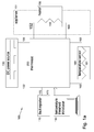
Figure 1 shows an aircraft heating system powered by an onboard power source comprising a DC generator. -
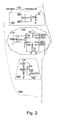
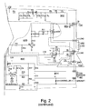
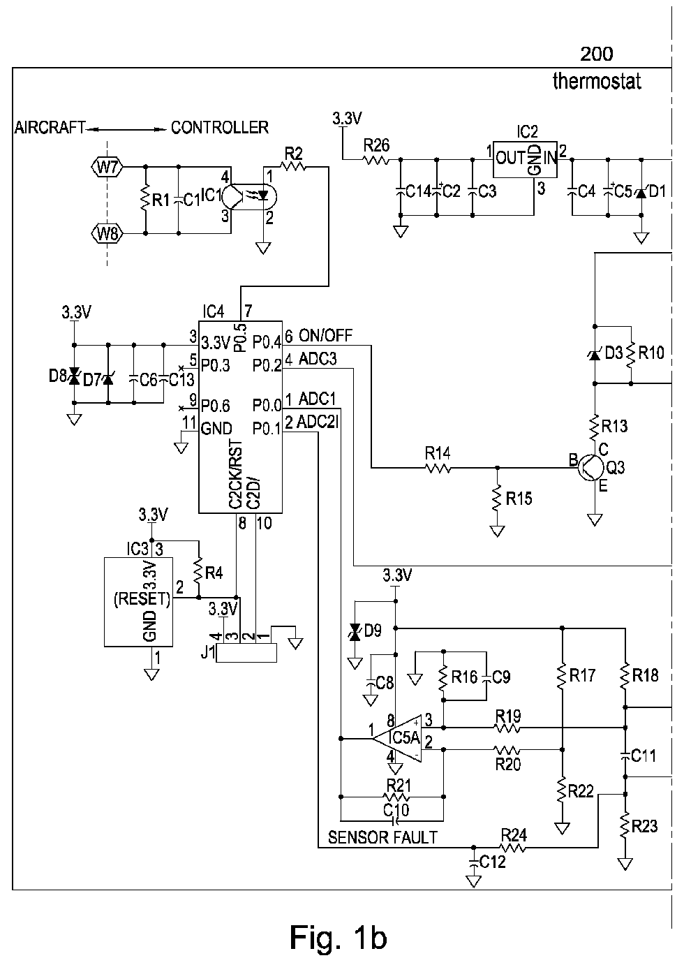
Figure 2 is diagram of the electrical circuit of the aircraft heating system. -
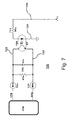
Figures 3-8 are more detailed diagram views of certain circuitries in the electrical circuit. -
Figure 9 shows a package integrating the electrical circuit of the aircraft heating system. - Referring now to the drawings, and initially to
Figure 1 , anaircraft heating system 100 is shown for heating anaircraft appliance 101. Theappliance 101 can comprise, for example, a deicer, a floor panel, a drainmast, a hose, a washing-water dispenser, a hot-beverage maker, or any other aircraft-associated appliance which needs to be heated. - A
power source 130 onboard the aircraft supplies DC power to theheating system 100. A small aircraft is commonly equipped with a 28 volt direct current electrical system. Such an electrical system can comprise a DC generator. Alternatively, the DC electrical system can be powered by alternator which stores energy in a battery. In either or any case, theheating system 100 is especially adapted to accommodate an aircraft wherein the heating of theappliance 101 is accomplished with DC power. - The illustrated
aircraft heating system 100 comprises aheater 150, atemperature sensor 160, afault reporter 170, and a setpoint introducer 180. - The
heater 150 is positioned to provide heat to or for theaircraft appliance 101. In the illustratedsystem 100, theheater 150 has an electrothermal design wherein the electrical power is converted to thermal energy via one or moreresistance heating elements 151. Electrical power is supplied to theheating element 151 via asupply line 152 and returned via areturn line 153. - The
sensor 160 is situated to sense a temperature meaningful to the reason theappliance 101 is being heated. To this end, the sensor can reside on theappliance 101, on theheater 150, or in a more relevant surrounding medium. In the illustratedsystem 100, thesensor 160 comprises aresistance element 161 having an impedance which varies as a function of temperature. Electrical power is supplied to theelement 161 via asupply line 162 and returned via areturn line 163. - The
fault reporter 170 can be located for easy reference, so it may be adjacent to or remote from theheater 150. In some aircraft, for example, thereporter 170 may be best located in the cockpit for inflight consideration by aircraft operators. Additionally or alternatively, it may be located for convenient access by ground personnel between flights. The input bus of thefault reporter 170 can include lines 172-173. - The setpoint introducer 180 allows an introduction or update of temperature-threshold information. As such information is typically not modified during flight; the
introducer 180 can be designed to allow selective connection of an input device 190 (e.g., a laptop computer) for data introduction. Theheating system 100 can have temperature thresholds input via theintroducer 180 prior to aircraft installation and/or after aircraft installation. Additionally or alternatively, theintroducer 180 can be used to adjust temperature thresholds between flights. - The
aircraft heating system 100 further comprises athermostat 200 which coordinates and/or controls theheater 150, thetemperature sensor 160, thefault reporter 170, and the setpoint introducer 180. - The
thermostat 200 comprises power-supplyingcircuitry 300,processing circuitry 400,heating circuitry 500, temperature-sensing circuitry 600, fault-reporting circuitry 700, and setpoint-introducingcircuitry 800. - Generally, the
circuitry 300 appropriately ushers power from theDC power source 130 to the heater-system components and other circuitries. Theprocessing circuitry 400 helps oversee overall thermostat operation by sending instructions to and/or receiving information from the other circuitries. Theheating circuitry 500 manages power supply to theheater 150 and preferably also detects heater-associated faults. Thesensing circuitry 600 conveys temperature information sensed by thesensor 160 and preferably also has sensor-fault-detecting features. The fault-reporting circuitry 700 reports fault-detection data to thereporter 170. And the setpoint-introducingcircuitry 800 allows the introduction of temperature-setpoint inputs through theintroducer 180. - The power-supplying
circuitry 300 receives power from theonboard source 130 and can include a terminal 311 (W3a) adapted for connection to thesupply line 132 of theDC power source 130. A circuit breaker 312 can be interposed between thesource supply line 132 and theterminal 311. A ground terminal 313 (W3b) with a voltage regulator (C3a) can be also be associated with thesource supply line 132. - The
circuitry 300 divides thesource supply line 132 into a high-voltage supply line 320 and a lowvoltage supply line 330. - The primary purpose of the
high voltage line 320 is to supply electrical power to theheater 150. To this end, theline 320 is connected in series with theheating element 151 of theheater 150. Specifically, for example, thecircuitry 300 can include a terminal 321(W3c) adapted for connection to theheater supply line 152 and a terminal 322 (W3d) adapted for connection to theheater return line 153. - Heater-power-control components of the heating circuitry 500 (namely a controller 540 introduced below) are connected in series with the
line 320 on the heater supply side. Heater-fault-detection components of the heating circuitry (namely a resistance 565, introduced below) are connected in series with theline 320 on the heater return side. - The high-
voltage supply line 320 can ground via thereturn line 133 of theDC power source 130, and a terminal 323 (W3e) can be adapted for this connection. A voltage regulator 324 (C3b) and/or a current regulator 325 (L3a) can be provided in parallel with theterminal 323. - The low-
voltage supply line 330 provides operating power to non-heating components of the aircraft system. In the illustrated embodiment, theline 330 is divided intosupply line 430 for theprocessing circuitry 400,supply line 530 for theheating circuitry 500,supply line 630 for the temperature-sensing circuitry 600, andsupply line 830 for the setpoint-introducingcircuitry 800. - The low-
voltage supply line 330 can include a power supervisor 331 (IC3). On the input side of thesupervisor 331, theline 330 can include a current regulator 332 (L3b), a reverse-polarity protector 333 (D3a), a power reducer 334 (R3a), an over-voltage protector 335 (D3b), and/or voltage storage 336 (C3c, C3d). On the outlet side of thesupervisor 331, theline 330 can include voltage storage 337 (C3e, C3f, C3g) and/or a filter 338 (R3b). - The
processing circuitry 400 can comprise amicroprocessor 410 to allow it to function as the "brains" of thethermostat 200. The microprocessor 440 can be a commercially available unit with sufficient computing strength and memory. Themicroprocessor 410 receives its operating power from the low-voltage line 330 of the power-supplyingcircuitry 300. - The low-
voltage supply line 430 is connected to themicroprocessor 410 viaport 431 and grounds therefrom viaport 432. Thecircuitry 400 can include components to protect and/or optimize microprocessor operation on the input side ofport 431. In the illustrated embodiment, these components include an electric-static-discharge protector 433 (D4a), an over-voltage protector 444 (D4b), an energy storage 445 (C4a, C4b), and/or a 446 noise suppressor (C4a, C4b). - The
microprocessor 410 provides heating instructions to theheating circuitry 500 based upon temperature data received from thesensing circuitry 600. Themicroprocessor 410 also receives fault-detection data from thecircuitries circuitry 700. Themicroprocessor 410 can further incorporate temperature-threshold data input through the introducingcircuitry 800 into its heating instructions. - To this end, the microprocessor 440 includes a plurality of ports connected to the other thermostat circuitries to send and receive information therebetween and/or thereamong. On-off instructions are sent to the
heating circuitry 500 through aport 451 and fault-detection data is received from the heating circuitry through aport 452. Aport 461 receives sensed-temperature information from thecircuitry 600 and theport 462 receives fault-detection data thecircuitry 600. Aport 471 sends fault-detection information to the fault-reportingcircuitry 700, aport 481 receives temperature setpoints input through the introducingcircuitry 800, and aport 482 which coordinates with reset functions of thecircuitry 800. - The
microprocessor 410 can manage power supply to theheater 150 based upon sensed temperature readings and one or more threshold values. Temperature thresholds can be introduced via theprogramming circuitry 800 before or after installation of thethermostat 200. Alternatively, thresholds can be pre-programmed into the microprocessor memory, wherebycircuitry 800 may not be necessary. - The temperature threshold can represent, for example, of a hot-enough temperature. If the sensed temperature is greater than this temperature, the microprocessor 440 will instruct the
heating circuitry 500 to convert to the off condition (or remain in the off condition) whereat heating power is not supplied theheater 150. Otherwise, the microprocessor 440 instructs theheating circuitry 500 to convert to or remain in the on condition whereat heating power supplied to theheater 150. - The
heating circuitry 500 comprises a heater controller 540 (Q5a) in series with the high-voltage supply line 320. The controller 540 is convertible between a heating condition, whereat power from the high-voltage supply line 320 flows to theheater 150, and a non-heating condition, whereat heating power does not flow to theheater 150. - The controller 540 is preferably a metal-oxide-semiconductor field effect transistor (MOSFET). The source and the drain of the switching transistor 540 are coupled to the high-
voltage line 320, with the drain being adjacent to theheater 150. An over-voltage protector 541 (D5a) can be provided for the controller 540. - The gate of the transistor 540 is coupled to a
line 542 and aparallel line 543 is coupled to the source-side. Theline 542 can include a quick-turnoff 544 (R5a, D5b). Theline 542 and/or theline 543 can include a gate-voltage limiter 545 (R5b, D5c). The lines 542-543 divide from aline 546 which can include current limiter 547 (R5c). - The
heating circuitry 500 also comprises an on-off switch 550 (Q5b) which is instructed by themicroprocessor 410. Theswitch 550 is preferably a bipolar transistor (npn) with its collector coupled to theline 546, its emitter coupled to aline 551 to ground, and its base coupled to aline 552. Theline 552 is connected to themicroprocessor port 451 and it can include a current limiter 553 (R5d) and/or a false-turn-on preventer 554 (R5e). - The switching of the
transistor 550 depends upon the output provided by themicroprocessor 410 through theport 451. When a relatively elevated output signal is provided, theswitch 550 is off and current is routed to ground. Thus, no current flows to the gate of the controller 540 whereby it is converted to, or remains in, its non-heating condition. - When a relatively depressed output signal is provided by the
microprocessor 410, theswitch 550 is on, and current flows to the gate of the controller 540. The controller 540 is converted to, or remains in, a heating condition whereat power is provided to theheater 150. - The
heating circuitry 500 can further comprise fault-detection features which receive operational power from the low-voltage line 530 ushered in by thepower supply circuitry 300. These features can include a comparator 550 (IC5) which grounds toline 551, receives input from lines 552-553, and outputs toline 554.Line 554 is coupled to themicroprocessor port 542 so as to provide fault-indicative signals thereto. For example, a "too high" signal indicates a short fault in theheater 150, and a "too low" signal indicates an open fault in theheater 150. - The input lines 552-553 divide from high-
voltage line 330 between theheater return 153 and ground. Resister 554 (R5f) can be situated on theline 330, resister 555 (R5h) can be situated online 552, and resister 556 (R5j) can be situated on the lines 551-552. A noise filter 557 (R5k, C5a) can be arranged with theground line 551 and theinput line 552, and/or a noise filter 558 (R51, C5b) can be arranged with theinput line 553 and theoutput line 554. - The temperature-
sensing circuitry 600 receives operational power fromsupply line 630 ushered thereto by the power-supplyingcircuitry 300. Theline 630 can be provided with an electric-static-discharge protector 631 (D6a). Thesupply line 630 splits into aline 640 and aline 650. - The
line 640 is coupled in series with theresister 161 of thesensor 160. Thecircuitry 600 can include a terminal 641 (W6a) adapted for connection to theline 162 of thesensor 160 and a terminal 642 (W6b) adapted for connection to itsline 163. On the output side of thesensor 160, theline 640 returns to themicroprocessor port 461 with a voltage indicative of a sensed temperature. A voltage reducer 644 (R6a), electric-static-discharge protectors 644-645 (D6b-D6c), a pull-down resistance 646 (R6b), a current reducer 647 (R6c), and/or a filter 648 (C6a) can be provided in theline 640. - The
line 650 can be routed to fault-detection features and can include a filter 651 (C6b). In the illustrated embodiment, these features include acomparator 660 which grounds toline 661, receives input from lines 662-663, and outputs toline 664.Line 664 is coupled to theport 462 to deliver fault-indicative information to themicroprocessor 410. - The input line 662 represents the reference voltage and the
input line 663 represents the voltage across thesensor 160. If the voltage across thesensor 160 is unreasonably low as compared to the reference voltage, this would be indicative of an open fault. If the voltage across thesensor 160 is unreasonably high relative to the reference voltage, this would be indicative of a short fault. The fault-detection features can further comprise appropriate filtering, scaling, and/or gaining components 671-672 (C6c-C6e, R6d-R6i). - Fault-
reporting circuitry 700 comprises aline 710 between themicroprocessor port 471 and a signal-transferring device 720 (IC7). A resistance 711 (R7a) can be placed on theline 710 on the input side of thedevice 720. In the illustrated embodiment, thesignal device 720 is an opti-isolator having aground line 721 and an output coupled to a communication bus comprising lines 722-723. Thecircuitry 700 can include terminals 724-725 (W7a-W7b) adapted for connection to the lines 172-173 of thereporter 170. A noise filter 726 (C7a, R7b) can also be provided. - Setpoint-introducing
circuitry 800 receives operating power from thesupply lines circuitry 300. In the illustrated embodiment, theline 830 supplies operating power to a junction 840 (J8) and theline 831 supplies operating power to the resetting device 850 (IC8). - The
junction 840 has aground line 841, an introducingline 842 connected to themicroprocessor port 481, and aline 843 associated with thedevice 850. Thejunction 840 is adapted for connection to the introducer 180 (e.g., a laptop) so that temperature setpoints may be introduced therethrough and conveyed to themicroprocessor 410 through theline 842. - The
resetting device 850 has aground line 851 and anoutput line 852 connected in parallel with theline 843 to areset line 854 leading to themicroprocessor port 482. A resistance 855 (R8a) is arranged in parallel with thedevice 850 between thesupply line 831 and theoutput line 852. If voltage reaches above a predetermined level, thecircuitry 800 is adapted to automatically reset (e.g., reboot) theintroducer 180. - The
thermostat 200 can be integrated into apackage 900 having relatively small dimensions. Specifically, for example, the package size can be less than six cm long, less than four cm wide, and/or less than two cm thick. Thepackage 900 can include a circuit board containing the circuitries 300-800. Heat sinks and/or insulation can be provided in a suitable manner. - Lead lines 931-932 and 977-978 can extend from one end of the
package 900, and lead lines 933-934 and 965- 966 can extend from its other end for convenient connection to the relevant components of theheating system 100. Specifically, for example, lead lines 931-932 and lead lines 933-934 can connect the power-supplyingcircuitry 300 to the power source 130 (e.g., terminals 311-312) and the heater 150 (e.g., terminals 321-322). Lead lines 963-964 can electrically connect thesensor 160 to the circuitry 600 (e.g., terminals 641-642). And lead lines 977-978 can electrically connect thefault reporter 170 the circuitry 700 (e.g., terminals 724-725). - One may now appreciate that the
aircraft heating system 100 incorporates solid-state switching equipment, is compatible with a DC power source, can detect/report faults in key components, and is selectively programmable. While theheating system 100, theappliance 101, thepower supply 130, theheater 150, thesensor 160, thereporter 170, theintroducer 180, thethermostat 200, the circuitries 300-800, and/or thepackage 900 have been shown and described with respect to a certain embodiment, other equivalent alterations and modifications will occur to others skilled in the art upon the reading and understanding of this disclosure.
Claims (15)
- A thermostat (200) for an aircraft heating system (100) supplied with DC power from an onboard source (130), said thermostat (200) comprising:power-supplying circuitry (300) including a source line (310) adapted for connection to a supply line (131) of the onboard DC power source (130), a high voltage line (320) providing heating power, and a low voltage line (330) providing operational power;processing circuitry (400) receiving operational power from the low voltage line (330) and formulating instructions relating to the heating power;heating circuitry (500) controlling supply of the heating power from the high voltage line (320) in accordance with the instructions formulated by the processing circuitry (400); andsensing circuitry (600) conveying a sensed temperature to the processing circuitry (400) for input when formulating the instructions relating to heating power;wherein the heating circuitry (500) and/or the sensing circuitry (600) also detect faults and report them to the processing circuitry (400).
- A thermostat (200) as set forth in the preceding claim, wherein the heating circuitry (500) comprises a controller (540) which controls the supply of the heating power from the high voltage line (320), this controller converting between a heating condition and a non-heating condition.
- A thermostat (200) as set forth in the preceding claim, wherein the controller (540) is connected in series with the high voltage line (320).
- A thermostat (200) as set forth in either of the two preceding claims, wherein the controller (540) is a field effect transistor (FET).
- A thermostat (200) as set forth in the preceding claim, wherein the controller (540) is a metal-oxide-semiconductor field effect transistor (MOSFET).
- A thermostat (200) as set forth in any of claims 2-5, wherein the heating circuitry (500) comprises a solid-state on-off switch (550) that switches between an on state and off state in response to instructions from the processing circuitry (400) and wherein this on-off switch (550) converts the controller (540) between its heating condition and its non-heating condition.
- A thermostat (200) as set forth in the preceding claim, wherein the on-off switch (550) is a transistor.
- A thermostat (200) as set forth in the preceding claim, wherein the on-off switch (550) is a bipolar transistor.
- A thermostat (200) as set forth in any of the preceding claims, wherein the heating circuitry (500) and/or the sensing circuitry (600) receives operational power from the low voltage line (330).
- A thermostat (200) as set forth in any of the preceding claims, wherein the heating circuitry (500) detects an open fault and/or a short fault.
- A thermostat (200) as set forth in any of the preceding claims, wherein the sensing circuitry (600) detects an open fault and/or a short fault.
- A thermostat (200) as set forth in any of the preceding claims, integrated into a package (900) that is less than six cm long, less than four cm wide, and/or less than two cm thick; wherein two pairs of lead lines (931-932, 977-978) extend out from one end of the package (900) and two pairs of lead lines (933-934, 965-966) extend out from the other end of the package (900).
- An aircraft heating system (100) comprising:a heater (150) positioned to provide heat to an aircraft appliance (101);a sensor (160) situated to sense a temperature relevant to the aircraft appliance (101); anda thermostat (200) as set forth in any of the preceding claims, wherein the power-supplying circuitry (300) is to the heater (150) and wherein the sensing circuitry (600) is coupled to the sensor (160).
- An aircraft heating system (100) as set forth in the preceding claim, further comprising a fault reporter (170); wherein fault-reporting circuitry (700) of the thermostat (200) conveys fault-relevant data to the reporter (170).
- An aircraft heating system (100) as set forth in either of the two preceding claims, comprising a programmer (180) selectively connectable to the thermostat (200) to introduce and/or update temperature-threshold information to the processing circuitry (400).
Applications Claiming Priority (1)
| Application Number | Priority Date | Filing Date | Title |
|---|---|---|---|
| US201161553965P | 2011-11-01 | 2011-11-01 |
Publications (2)
| Publication Number | Publication Date |
|---|---|
| EP2595026A1 true EP2595026A1 (en) | 2013-05-22 |
| EP2595026B1 EP2595026B1 (en) | 2014-03-19 |
Family
ID=47257456
Family Applications (1)
| Application Number | Title | Priority Date | Filing Date |
|---|---|---|---|
| EP12190737.2A Active EP2595026B1 (en) | 2011-11-01 | 2012-10-31 | Aircraft heating system |
Country Status (4)
| Country | Link |
|---|---|
| US (1) | US9046899B2 (en) |
| EP (1) | EP2595026B1 (en) |
| BR (1) | BR102012028021B1 (en) |
| CA (1) | CA2794172C (en) |
Cited By (3)
| Publication number | Priority date | Publication date | Assignee | Title |
|---|---|---|---|---|
| WO2018191189A1 (en) * | 2017-04-10 | 2018-10-18 | B/E Aerospace, Inc. | Inline heater controller |
| CN110077606A (en) * | 2018-01-25 | 2019-08-02 | 哈米尔顿森德斯特兰德公司 | The fuel tank of aircraft is catalyzed inerting equipment |
| CN114455085A (en) * | 2022-03-18 | 2022-05-10 | 成都科洛威尔科技有限公司 | Pitot tube heating alarm unit of general aircraft |
Families Citing this family (16)
| Publication number | Priority date | Publication date | Assignee | Title |
|---|---|---|---|---|
| CN105035355B (en) * | 2015-08-12 | 2017-03-08 | 中国航空工业集团公司西安飞机设计研究所 | A thermal load power simulation method and a thermal load simulation system |
| EP3153402B1 (en) * | 2015-10-09 | 2018-04-25 | Airbus Operations GmbH | A heated floor panel system for an aircraft |
| US11060992B2 (en) | 2017-03-24 | 2021-07-13 | Rosemount Aerospace Inc. | Probe heater remaining useful life determination |
| US10914777B2 (en) | 2017-03-24 | 2021-02-09 | Rosemount Aerospace Inc. | Probe heater remaining useful life determination |
| US10895592B2 (en) | 2017-03-24 | 2021-01-19 | Rosemount Aerospace Inc. | Probe heater remaining useful life determination |
| US11414196B2 (en) * | 2017-10-30 | 2022-08-16 | Battelle Memorial Institute | Ice protection system and controller |
| RU2666886C1 (en) * | 2017-11-14 | 2018-09-12 | Акционерное общество "Объединенная двигателестроительная корпорация" (АО "ОДК") | Method of management of the anti-icing system of the air intake of the gas turbine engine of the aircraft |
| US10962580B2 (en) | 2018-12-14 | 2021-03-30 | Rosemount Aerospace Inc. | Electric arc detection for probe heater PHM and prediction of remaining useful life |
| US11061080B2 (en) | 2018-12-14 | 2021-07-13 | Rosemount Aerospace Inc. | Real time operational leakage current measurement for probe heater PHM and prediction of remaining useful life |
| US11604209B2 (en) | 2019-05-17 | 2023-03-14 | Rosemount Aerospace Inc. | Pitot heater health monitoring system |
| US11639954B2 (en) | 2019-05-29 | 2023-05-02 | Rosemount Aerospace Inc. | Differential leakage current measurement for heater health monitoring |
| US11472562B2 (en) | 2019-06-14 | 2022-10-18 | Rosemount Aerospace Inc. | Health monitoring of an electrical heater of an air data probe |
| US11930563B2 (en) | 2019-09-16 | 2024-03-12 | Rosemount Aerospace Inc. | Monitoring and extending heater life through power supply polarity switching |
| US11293995B2 (en) | 2020-03-23 | 2022-04-05 | Rosemount Aerospace Inc. | Differential leakage current measurement for heater health monitoring |
| US11630140B2 (en) | 2020-04-22 | 2023-04-18 | Rosemount Aerospace Inc. | Prognostic health monitoring for heater |
| CN114675625B (en) * | 2022-03-21 | 2024-11-19 | 潍柴动力股份有限公司 | Controller control method and device |
Citations (5)
| Publication number | Priority date | Publication date | Assignee | Title |
|---|---|---|---|---|
| DE2443224A1 (en) * | 1974-09-10 | 1976-03-25 | Licentia Gmbh | PROCESS FOR DE-ICING OF ENGINE, WING AND TAIL SYSTEMS ON AIRCRAFT |
| US6218647B1 (en) * | 1998-01-19 | 2001-04-17 | Msx, Inc. | Method and apparatus for using direct current to detect ground faults in a shielded heater wire |
| US7104462B2 (en) | 2004-01-09 | 2006-09-12 | Goodrich Corporation | Low noise solid-state thermostat with microprocessor controlled fault detection and reporting, and programmable set points |
| US20080046129A1 (en) * | 2003-08-20 | 2008-02-21 | Watlow Electric Manufacturing Company | Variable wattage control system |
| US20110192830A1 (en) * | 2010-02-11 | 2011-08-11 | Aervoe Industries, Incorporated | Portable Stove and Slow Cooker |
Family Cites Families (33)
| Publication number | Priority date | Publication date | Assignee | Title |
|---|---|---|---|---|
| US3456455A (en) | 1967-09-22 | 1969-07-22 | Itt | Temperature controller for environmental chamber |
| US4282423A (en) | 1979-05-18 | 1981-08-04 | International Foodservice Equipment Systems, Inc. | Deep fat fryer having a solid-state control circuit |
| DE3023753C2 (en) | 1980-06-25 | 1986-06-26 | CENTRA-BÜRKLE GmbH, 7036 Schönaich | Circuit arrangement |
| US4455509A (en) * | 1983-05-16 | 1984-06-19 | Crum Stephen T | Intrinsically safe lighting system |
| CA1271825A (en) | 1986-11-17 | 1990-07-17 | Brian E. Mcdonnell | Line voltage two wire thermostat |
| US5229579A (en) * | 1987-05-13 | 1993-07-20 | Nartron Corporation | Motor vehicle heated seat control |
| US5397991A (en) | 1988-07-13 | 1995-03-14 | Electronic Development Inc. | Multi-battery charging system for reduced fuel consumption and emissions in automotive vehicles |
| US5063836A (en) | 1989-01-25 | 1991-11-12 | Cafe 98 Industries Ltd. | Coffee making machine and components thereof |
| JPH05299991A (en) | 1991-06-06 | 1993-11-12 | Nec Corp | Monolithic power mos integrated circuit |
| US5592989A (en) | 1994-04-28 | 1997-01-14 | Landis & Gyr Powers, Inc. | Electronic thermostat having high and low voltage control capability |
| US5765994A (en) | 1995-07-14 | 1998-06-16 | Barbier; William J. | Low oil detector with automatic reset |
| AU7016396A (en) | 1995-10-10 | 1997-04-30 | Donald Kuhnel | Fluid heater with improved heating elements controller |
| US5832178A (en) | 1996-06-25 | 1998-11-03 | Crafco, Incorporated | Hot melt mix applicator with electrically heated hose and wand with temperature-controlled electric generator |
| US5861610A (en) * | 1997-03-21 | 1999-01-19 | Micro Weiss Electronics | Heater wire with integral sensor wire and improved controller for same |
| US6080971A (en) | 1997-05-22 | 2000-06-27 | David Seitz | Fluid heater with improved heating elements controller |
| EP0924588A1 (en) | 1997-10-16 | 1999-06-23 | Varma, Dhruv | Electronic thermostat control unit and its use in multipoint temperature controller for refrigeration and heating systems |
| US5924486A (en) | 1997-10-29 | 1999-07-20 | Tecom, Inc. | Environmental condition control and energy management system and method |
| US6134134A (en) | 1998-04-21 | 2000-10-17 | Dushane; Steve | Thermostat voltage adapter |
| IL139676A (en) | 1998-05-15 | 2005-12-18 | Vasu Tech Ltd | Multipoint digital temperatur controller |
| US6396032B1 (en) | 2000-02-29 | 2002-05-28 | Athena Controls, Inc. | Oven temperature control circuit |
| US6772961B2 (en) * | 2000-06-16 | 2004-08-10 | Ati Properties, Inc. | Methods and apparatus for spray forming, atomization and heat transfer |
| US6691923B2 (en) * | 2001-05-31 | 2004-02-17 | Goodrich Corporation | Low noise solid-state thermostat |
| US20040035197A1 (en) * | 2002-08-26 | 2004-02-26 | D'antonio Nicholas F. | Airline coffee brewer |
| US7006900B2 (en) | 2002-11-14 | 2006-02-28 | Asm International N.V. | Hybrid cascade model-based predictive control system |
| US6998584B1 (en) | 2004-09-03 | 2006-02-14 | Caterpillar Inc. | System for output power control on electric heater drive |
| US7583130B2 (en) | 2004-10-14 | 2009-09-01 | Analog Devices, Inc. | Input biasing system for bracketing a floating power supply about an input signal |
| US8003922B2 (en) | 2006-02-17 | 2011-08-23 | Phillips & Temro Industries Inc. | Solid state switch with over-temperature and over-current protection |
| US7557330B2 (en) | 2006-05-12 | 2009-07-07 | Goodrich Corporation | Heated floor panel with integrated controller having ground fault interrupt circuit |
| US7346468B2 (en) | 2006-08-08 | 2008-03-18 | International Business Machines Corporation | Method and apparatus for detecting heat sink faults |
| US7737762B2 (en) * | 2006-09-12 | 2010-06-15 | Energate Inc | Solid-state switch |
| US7524107B1 (en) | 2006-09-29 | 2009-04-28 | National Semiconductor Corporation | Dual purpose output thermostat |
| JP5247513B2 (en) * | 2009-02-12 | 2013-07-24 | 株式会社沖データ | Power supply device and image forming apparatus |
| TW201122750A (en) | 2009-12-28 | 2011-07-01 | Hon Hai Prec Ind Co Ltd | Temperature control circuit |
-
2012
- 2012-10-26 US US13/661,959 patent/US9046899B2/en active Active
- 2012-10-31 EP EP12190737.2A patent/EP2595026B1/en active Active
- 2012-10-31 CA CA2794172A patent/CA2794172C/en active Active
- 2012-10-31 BR BR102012028021-3A patent/BR102012028021B1/en not_active IP Right Cessation
Patent Citations (5)
| Publication number | Priority date | Publication date | Assignee | Title |
|---|---|---|---|---|
| DE2443224A1 (en) * | 1974-09-10 | 1976-03-25 | Licentia Gmbh | PROCESS FOR DE-ICING OF ENGINE, WING AND TAIL SYSTEMS ON AIRCRAFT |
| US6218647B1 (en) * | 1998-01-19 | 2001-04-17 | Msx, Inc. | Method and apparatus for using direct current to detect ground faults in a shielded heater wire |
| US20080046129A1 (en) * | 2003-08-20 | 2008-02-21 | Watlow Electric Manufacturing Company | Variable wattage control system |
| US7104462B2 (en) | 2004-01-09 | 2006-09-12 | Goodrich Corporation | Low noise solid-state thermostat with microprocessor controlled fault detection and reporting, and programmable set points |
| US20110192830A1 (en) * | 2010-02-11 | 2011-08-11 | Aervoe Industries, Incorporated | Portable Stove and Slow Cooker |
Cited By (4)
| Publication number | Priority date | Publication date | Assignee | Title |
|---|---|---|---|---|
| WO2018191189A1 (en) * | 2017-04-10 | 2018-10-18 | B/E Aerospace, Inc. | Inline heater controller |
| US10583928B2 (en) | 2017-04-10 | 2020-03-10 | B/E Aerospace, Inc. | Inline heater controller |
| CN110077606A (en) * | 2018-01-25 | 2019-08-02 | 哈米尔顿森德斯特兰德公司 | The fuel tank of aircraft is catalyzed inerting equipment |
| CN114455085A (en) * | 2022-03-18 | 2022-05-10 | 成都科洛威尔科技有限公司 | Pitot tube heating alarm unit of general aircraft |
Also Published As
| Publication number | Publication date |
|---|---|
| BR102012028021A2 (en) | 2015-07-28 |
| CA2794172A1 (en) | 2013-05-01 |
| CA2794172C (en) | 2020-04-07 |
| US20140332521A1 (en) | 2014-11-13 |
| US9046899B2 (en) | 2015-06-02 |
| BR102012028021B1 (en) | 2021-08-10 |
| EP2595026B1 (en) | 2014-03-19 |
Similar Documents
| Publication | Publication Date | Title |
|---|---|---|
| EP2595026B1 (en) | Aircraft heating system | |
| US8612067B2 (en) | System for deicing and/or defogging an aircraft surface, method for controlling same, and aircraft equipped with same | |
| EP1897198B1 (en) | Leakage current shunt in an electrical power distribution system utilizing solid state relays | |
| US20110062936A1 (en) | Ac power switching module | |
| US8749928B2 (en) | Aircraft electrical appliance | |
| US20030178412A1 (en) | Propeller de-icing system | |
| JPH03198617A (en) | Power controller | |
| EP3618211B1 (en) | Direct current over voltage monitoring and protection | |
| EP2719623B1 (en) | Heating control unit comprising a sensor, ice protection system and method for controlling a heater | |
| KR20180003857A (en) | Switchboard to detect and regulate temperature and voltage | |
| EP2898663A1 (en) | System and method for supplying power to surveillance video cameras and protection cases for such video cameras | |
| US3386004A (en) | Low voltage safety circuit for electric power units | |
| US7622818B2 (en) | Backup electrical power system for solid-state aircraft power distribution systems | |
| EP2860837A1 (en) | Virtual circuit breaker | |
| US7928679B2 (en) | Protection arrangement of an electric motor | |
| US3424919A (en) | Remote control system for electrical apparatus | |
| US20160233664A1 (en) | Automatic wiring board | |
| WO2016094797A3 (en) | Rotor ice protection system | |
| EP3499721B1 (en) | Circuit and system implementing a power supply configured for spark prevention | |
| CN106208256A (en) | Airborne electronic equipment terminal charge module | |
| KR20230127656A (en) | Power management system in a cattle shed and operation method therefor | |
| CN108134371A (en) | Overtemperature and overcurrent protective device in electronic instrument checkout procedure | |
| US3441802A (en) | Voltage responsive relay type quantizer for monitoring plural sources | |
| CN109643887A (en) | Protective switch device | |
| JPH06147604A (en) | Power supplying device for separation type air conditioner |
Legal Events
| Date | Code | Title | Description |
|---|---|---|---|
| PUAI | Public reference made under article 153(3) epc to a published international application that has entered the european phase |
Free format text: ORIGINAL CODE: 0009012 |
|
| 17P | Request for examination filed |
Effective date: 20121031 |
|
| AK | Designated contracting states |
Kind code of ref document: A1 Designated state(s): AL AT BE BG CH CY CZ DE DK EE ES FI FR GB GR HR HU IE IS IT LI LT LU LV MC MK MT NL NO PL PT RO RS SE SI SK SM TR |
|
| AX | Request for extension of the european patent |
Extension state: BA ME |
|
| GRAP | Despatch of communication of intention to grant a patent |
Free format text: ORIGINAL CODE: EPIDOSNIGR1 |
|
| RIN1 | Information on inventor provided before grant (corrected) |
Inventor name: SHEARER, JON DOUGLAS Inventor name: AESHLIMAN, CARL R. |
|
| INTG | Intention to grant announced |
Effective date: 20131126 |
|
| GRAS | Grant fee paid |
Free format text: ORIGINAL CODE: EPIDOSNIGR3 |
|
| GRAA | (expected) grant |
Free format text: ORIGINAL CODE: 0009210 |
|
| AK | Designated contracting states |
Kind code of ref document: B1 Designated state(s): AL AT BE BG CH CY CZ DE DK EE ES FI FR GB GR HR HU IE IS IT LI LT LU LV MC MK MT NL NO PL PT RO RS SE SI SK SM TR |
|
| REG | Reference to a national code |
Ref country code: GB Ref legal event code: FG4D |
|
| REG | Reference to a national code |
Ref country code: CH Ref legal event code: EP |
|
| REG | Reference to a national code |
Ref country code: AT Ref legal event code: REF Ref document number: 658060 Country of ref document: AT Kind code of ref document: T Effective date: 20140415 |
|
| REG | Reference to a national code |
Ref country code: IE Ref legal event code: FG4D |
|
| REG | Reference to a national code |
Ref country code: DE Ref legal event code: R096 Ref document number: 602012001137 Country of ref document: DE Effective date: 20140430 |
|
| PG25 | Lapsed in a contracting state [announced via postgrant information from national office to epo] |
Ref country code: NO Free format text: LAPSE BECAUSE OF FAILURE TO SUBMIT A TRANSLATION OF THE DESCRIPTION OR TO PAY THE FEE WITHIN THE PRESCRIBED TIME-LIMIT Effective date: 20140619 Ref country code: LT Free format text: LAPSE BECAUSE OF FAILURE TO SUBMIT A TRANSLATION OF THE DESCRIPTION OR TO PAY THE FEE WITHIN THE PRESCRIBED TIME-LIMIT Effective date: 20140319 |
|
| REG | Reference to a national code |
Ref country code: NL Ref legal event code: VDEP Effective date: 20140319 |
|
| REG | Reference to a national code |
Ref country code: AT Ref legal event code: MK05 Ref document number: 658060 Country of ref document: AT Kind code of ref document: T Effective date: 20140319 |
|
| REG | Reference to a national code |
Ref country code: LT Ref legal event code: MG4D |
|
| PG25 | Lapsed in a contracting state [announced via postgrant information from national office to epo] |
Ref country code: SE Free format text: LAPSE BECAUSE OF FAILURE TO SUBMIT A TRANSLATION OF THE DESCRIPTION OR TO PAY THE FEE WITHIN THE PRESCRIBED TIME-LIMIT Effective date: 20140319 Ref country code: CY Free format text: LAPSE BECAUSE OF FAILURE TO SUBMIT A TRANSLATION OF THE DESCRIPTION OR TO PAY THE FEE WITHIN THE PRESCRIBED TIME-LIMIT Effective date: 20140319 Ref country code: FI Free format text: LAPSE BECAUSE OF FAILURE TO SUBMIT A TRANSLATION OF THE DESCRIPTION OR TO PAY THE FEE WITHIN THE PRESCRIBED TIME-LIMIT Effective date: 20140319 |
|
| PG25 | Lapsed in a contracting state [announced via postgrant information from national office to epo] |
Ref country code: HR Free format text: LAPSE BECAUSE OF FAILURE TO SUBMIT A TRANSLATION OF THE DESCRIPTION OR TO PAY THE FEE WITHIN THE PRESCRIBED TIME-LIMIT Effective date: 20140319 Ref country code: RS Free format text: LAPSE BECAUSE OF FAILURE TO SUBMIT A TRANSLATION OF THE DESCRIPTION OR TO PAY THE FEE WITHIN THE PRESCRIBED TIME-LIMIT Effective date: 20140319 Ref country code: LV Free format text: LAPSE BECAUSE OF FAILURE TO SUBMIT A TRANSLATION OF THE DESCRIPTION OR TO PAY THE FEE WITHIN THE PRESCRIBED TIME-LIMIT Effective date: 20140319 |
|
| PG25 | Lapsed in a contracting state [announced via postgrant information from national office to epo] |
Ref country code: BG Free format text: LAPSE BECAUSE OF FAILURE TO SUBMIT A TRANSLATION OF THE DESCRIPTION OR TO PAY THE FEE WITHIN THE PRESCRIBED TIME-LIMIT Effective date: 20140619 Ref country code: NL Free format text: LAPSE BECAUSE OF FAILURE TO SUBMIT A TRANSLATION OF THE DESCRIPTION OR TO PAY THE FEE WITHIN THE PRESCRIBED TIME-LIMIT Effective date: 20140319 Ref country code: BE Free format text: LAPSE BECAUSE OF FAILURE TO SUBMIT A TRANSLATION OF THE DESCRIPTION OR TO PAY THE FEE WITHIN THE PRESCRIBED TIME-LIMIT Effective date: 20140319 Ref country code: RO Free format text: LAPSE BECAUSE OF FAILURE TO SUBMIT A TRANSLATION OF THE DESCRIPTION OR TO PAY THE FEE WITHIN THE PRESCRIBED TIME-LIMIT Effective date: 20140319 Ref country code: IS Free format text: LAPSE BECAUSE OF FAILURE TO SUBMIT A TRANSLATION OF THE DESCRIPTION OR TO PAY THE FEE WITHIN THE PRESCRIBED TIME-LIMIT Effective date: 20140719 Ref country code: EE Free format text: LAPSE BECAUSE OF FAILURE TO SUBMIT A TRANSLATION OF THE DESCRIPTION OR TO PAY THE FEE WITHIN THE PRESCRIBED TIME-LIMIT Effective date: 20140319 Ref country code: CZ Free format text: LAPSE BECAUSE OF FAILURE TO SUBMIT A TRANSLATION OF THE DESCRIPTION OR TO PAY THE FEE WITHIN THE PRESCRIBED TIME-LIMIT Effective date: 20140319 |
|
| PG25 | Lapsed in a contracting state [announced via postgrant information from national office to epo] |
Ref country code: ES Free format text: LAPSE BECAUSE OF FAILURE TO SUBMIT A TRANSLATION OF THE DESCRIPTION OR TO PAY THE FEE WITHIN THE PRESCRIBED TIME-LIMIT Effective date: 20140319 Ref country code: SK Free format text: LAPSE BECAUSE OF FAILURE TO SUBMIT A TRANSLATION OF THE DESCRIPTION OR TO PAY THE FEE WITHIN THE PRESCRIBED TIME-LIMIT Effective date: 20140319 Ref country code: AT Free format text: LAPSE BECAUSE OF FAILURE TO SUBMIT A TRANSLATION OF THE DESCRIPTION OR TO PAY THE FEE WITHIN THE PRESCRIBED TIME-LIMIT Effective date: 20140319 Ref country code: PL Free format text: LAPSE BECAUSE OF FAILURE TO SUBMIT A TRANSLATION OF THE DESCRIPTION OR TO PAY THE FEE WITHIN THE PRESCRIBED TIME-LIMIT Effective date: 20140319 |
|
| REG | Reference to a national code |
Ref country code: DE Ref legal event code: R097 Ref document number: 602012001137 Country of ref document: DE |
|
| PG25 | Lapsed in a contracting state [announced via postgrant information from national office to epo] |
Ref country code: PT Free format text: LAPSE BECAUSE OF FAILURE TO SUBMIT A TRANSLATION OF THE DESCRIPTION OR TO PAY THE FEE WITHIN THE PRESCRIBED TIME-LIMIT Effective date: 20140721 |
|
| PLBE | No opposition filed within time limit |
Free format text: ORIGINAL CODE: 0009261 |
|
| STAA | Information on the status of an ep patent application or granted ep patent |
Free format text: STATUS: NO OPPOSITION FILED WITHIN TIME LIMIT |
|
| PG25 | Lapsed in a contracting state [announced via postgrant information from national office to epo] |
Ref country code: DK Free format text: LAPSE BECAUSE OF FAILURE TO SUBMIT A TRANSLATION OF THE DESCRIPTION OR TO PAY THE FEE WITHIN THE PRESCRIBED TIME-LIMIT Effective date: 20140319 |
|
| 26N | No opposition filed |
Effective date: 20141222 |
|
| PG25 | Lapsed in a contracting state [announced via postgrant information from national office to epo] |
Ref country code: IT Free format text: LAPSE BECAUSE OF FAILURE TO SUBMIT A TRANSLATION OF THE DESCRIPTION OR TO PAY THE FEE WITHIN THE PRESCRIBED TIME-LIMIT Effective date: 20140319 |
|
| REG | Reference to a national code |
Ref country code: DE Ref legal event code: R097 Ref document number: 602012001137 Country of ref document: DE Effective date: 20141222 |
|
| PG25 | Lapsed in a contracting state [announced via postgrant information from national office to epo] |
Ref country code: LU Free format text: LAPSE BECAUSE OF FAILURE TO SUBMIT A TRANSLATION OF THE DESCRIPTION OR TO PAY THE FEE WITHIN THE PRESCRIBED TIME-LIMIT Effective date: 20141031 Ref country code: MC Free format text: LAPSE BECAUSE OF FAILURE TO SUBMIT A TRANSLATION OF THE DESCRIPTION OR TO PAY THE FEE WITHIN THE PRESCRIBED TIME-LIMIT Effective date: 20140319 |
|
| REG | Reference to a national code |
Ref country code: IE Ref legal event code: MM4A |
|
| PG25 | Lapsed in a contracting state [announced via postgrant information from national office to epo] |
Ref country code: SI Free format text: LAPSE BECAUSE OF FAILURE TO SUBMIT A TRANSLATION OF THE DESCRIPTION OR TO PAY THE FEE WITHIN THE PRESCRIBED TIME-LIMIT Effective date: 20140319 |
|
| PG25 | Lapsed in a contracting state [announced via postgrant information from national office to epo] |
Ref country code: IE Free format text: LAPSE BECAUSE OF NON-PAYMENT OF DUE FEES Effective date: 20141031 |
|
| REG | Reference to a national code |
Ref country code: CH Ref legal event code: PL |
|
| PG25 | Lapsed in a contracting state [announced via postgrant information from national office to epo] |
Ref country code: GR Free format text: LAPSE BECAUSE OF FAILURE TO SUBMIT A TRANSLATION OF THE DESCRIPTION OR TO PAY THE FEE WITHIN THE PRESCRIBED TIME-LIMIT Effective date: 20140620 |
|
| PG25 | Lapsed in a contracting state [announced via postgrant information from national office to epo] |
Ref country code: LI Free format text: LAPSE BECAUSE OF NON-PAYMENT OF DUE FEES Effective date: 20151031 Ref country code: HU Free format text: LAPSE BECAUSE OF FAILURE TO SUBMIT A TRANSLATION OF THE DESCRIPTION OR TO PAY THE FEE WITHIN THE PRESCRIBED TIME-LIMIT; INVALID AB INITIO Effective date: 20121031 Ref country code: CH Free format text: LAPSE BECAUSE OF NON-PAYMENT OF DUE FEES Effective date: 20151031 Ref country code: TR Free format text: LAPSE BECAUSE OF FAILURE TO SUBMIT A TRANSLATION OF THE DESCRIPTION OR TO PAY THE FEE WITHIN THE PRESCRIBED TIME-LIMIT Effective date: 20140319 Ref country code: MT Free format text: LAPSE BECAUSE OF FAILURE TO SUBMIT A TRANSLATION OF THE DESCRIPTION OR TO PAY THE FEE WITHIN THE PRESCRIBED TIME-LIMIT Effective date: 20140319 |
|
| REG | Reference to a national code |
Ref country code: FR Ref legal event code: PLFP Year of fee payment: 5 |
|
| PG25 | Lapsed in a contracting state [announced via postgrant information from national office to epo] |
Ref country code: SM Free format text: LAPSE BECAUSE OF FAILURE TO SUBMIT A TRANSLATION OF THE DESCRIPTION OR TO PAY THE FEE WITHIN THE PRESCRIBED TIME-LIMIT Effective date: 20140319 |
|
| REG | Reference to a national code |
Ref country code: DE Ref legal event code: R082 Ref document number: 602012001137 Country of ref document: DE Representative=s name: SCHMITT-NILSON SCHRAUD WAIBEL WOHLFROM PATENTA, DE |
|
| REG | Reference to a national code |
Ref country code: FR Ref legal event code: PLFP Year of fee payment: 6 |
|
| PG25 | Lapsed in a contracting state [announced via postgrant information from national office to epo] |
Ref country code: MK Free format text: LAPSE BECAUSE OF FAILURE TO SUBMIT A TRANSLATION OF THE DESCRIPTION OR TO PAY THE FEE WITHIN THE PRESCRIBED TIME-LIMIT Effective date: 20140319 |
|
| REG | Reference to a national code |
Ref country code: FR Ref legal event code: PLFP Year of fee payment: 7 |
|
| PG25 | Lapsed in a contracting state [announced via postgrant information from national office to epo] |
Ref country code: AL Free format text: LAPSE BECAUSE OF FAILURE TO SUBMIT A TRANSLATION OF THE DESCRIPTION OR TO PAY THE FEE WITHIN THE PRESCRIBED TIME-LIMIT Effective date: 20140319 |
|
| P01 | Opt-out of the competence of the unified patent court (upc) registered |
Effective date: 20230522 |
|
| PGFP | Annual fee paid to national office [announced via postgrant information from national office to epo] |
Ref country code: GB Payment date: 20250923 Year of fee payment: 14 |
|
| PGFP | Annual fee paid to national office [announced via postgrant information from national office to epo] |
Ref country code: FR Payment date: 20250923 Year of fee payment: 14 |
|
| PGFP | Annual fee paid to national office [announced via postgrant information from national office to epo] |
Ref country code: DE Payment date: 20250923 Year of fee payment: 14 |