EP2594966A2 - Elektromagnetisches Sensorkabel und elektrische Konfiguration dafür - Google Patents
Elektromagnetisches Sensorkabel und elektrische Konfiguration dafür Download PDFInfo
- Publication number
- EP2594966A2 EP2594966A2 EP12193665.2A EP12193665A EP2594966A2 EP 2594966 A2 EP2594966 A2 EP 2594966A2 EP 12193665 A EP12193665 A EP 12193665A EP 2594966 A2 EP2594966 A2 EP 2594966A2
- Authority
- EP
- European Patent Office
- Prior art keywords
- sensor cable
- electrodes
- cable segment
- signal processing
- processing module
- Prior art date
- Legal status (The legal status is an assumption and is not a legal conclusion. Google has not performed a legal analysis and makes no representation as to the accuracy of the status listed.)
- Granted
Links
- 239000004020 conductor Substances 0.000 claims abstract description 34
- XLYOFNOQVPJJNP-UHFFFAOYSA-N water Substances O XLYOFNOQVPJJNP-UHFFFAOYSA-N 0.000 claims abstract description 34
- 238000005259 measurement Methods 0.000 claims description 12
- 230000005405 multipole Effects 0.000 claims description 11
- 230000003287 optical effect Effects 0.000 claims description 8
- 239000013307 optical fiber Substances 0.000 claims description 4
- 238000000034 method Methods 0.000 claims 15
- 230000002194 synthesizing effect Effects 0.000 claims 2
- 230000015572 biosynthetic process Effects 0.000 description 14
- 230000005672 electromagnetic field Effects 0.000 description 14
- 238000005755 formation reaction Methods 0.000 description 12
- 125000006850 spacer group Chemical group 0.000 description 5
- 230000001939 inductive effect Effects 0.000 description 4
- 239000000463 material Substances 0.000 description 4
- 230000005684 electric field Effects 0.000 description 3
- 239000011435 rock Substances 0.000 description 3
- 238000010276 construction Methods 0.000 description 2
- 230000007423 decrease Effects 0.000 description 2
- 239000004033 plastic Substances 0.000 description 2
- 229920003023 plastic Polymers 0.000 description 2
- -1 polypropylene Polymers 0.000 description 2
- 238000003786 synthesis reaction Methods 0.000 description 2
- 239000011800 void material Substances 0.000 description 2
- 239000004215 Carbon black (E152) Substances 0.000 description 1
- 239000004743 Polypropylene Substances 0.000 description 1
- RTAQQCXQSZGOHL-UHFFFAOYSA-N Titanium Chemical compound [Ti] RTAQQCXQSZGOHL-UHFFFAOYSA-N 0.000 description 1
- 239000003795 chemical substances by application Substances 0.000 description 1
- 238000004891 communication Methods 0.000 description 1
- 230000008094 contradictory effect Effects 0.000 description 1
- 238000013500 data storage Methods 0.000 description 1
- 238000004146 energy storage Methods 0.000 description 1
- 239000000945 filler Substances 0.000 description 1
- 239000013056 hazardous product Substances 0.000 description 1
- 229930195733 hydrocarbon Natural products 0.000 description 1
- 125000001183 hydrocarbyl group Chemical group 0.000 description 1
- 239000003350 kerosene Substances 0.000 description 1
- 239000007788 liquid Substances 0.000 description 1
- 230000000379 polymerizing effect Effects 0.000 description 1
- 229920001155 polypropylene Polymers 0.000 description 1
- 229920002635 polyurethane Polymers 0.000 description 1
- 239000004814 polyurethane Substances 0.000 description 1
- 230000002441 reversible effect Effects 0.000 description 1
- 238000000926 separation method Methods 0.000 description 1
- 239000007787 solid Substances 0.000 description 1
- 229910001220 stainless steel Inorganic materials 0.000 description 1
- 239000010935 stainless steel Substances 0.000 description 1
- 239000012209 synthetic fiber Substances 0.000 description 1
- 229920002994 synthetic fiber Polymers 0.000 description 1
- 229910052719 titanium Inorganic materials 0.000 description 1
- 239000010936 titanium Substances 0.000 description 1
- 230000001052 transient effect Effects 0.000 description 1
Images


Classifications
-
- G—PHYSICS
- G01—MEASURING; TESTING
- G01V—GEOPHYSICS; GRAVITATIONAL MEASUREMENTS; DETECTING MASSES OR OBJECTS; TAGS
- G01V3/00—Electric or magnetic prospecting or detecting; Measuring magnetic field characteristics of the earth, e.g. declination, deviation
- G01V3/08—Electric or magnetic prospecting or detecting; Measuring magnetic field characteristics of the earth, e.g. declination, deviation operating with magnetic or electric fields produced or modified by objects or geological structures or by detecting devices
- G01V3/083—Controlled source electromagnetic [CSEM] surveying
-
- G—PHYSICS
- G01—MEASURING; TESTING
- G01V—GEOPHYSICS; GRAVITATIONAL MEASUREMENTS; DETECTING MASSES OR OBJECTS; TAGS
- G01V1/00—Seismology; Seismic or acoustic prospecting or detecting
- G01V1/16—Receiving elements for seismic signals; Arrangements or adaptations of receiving elements
- G01V1/20—Arrangements of receiving elements, e.g. geophone pattern
- G01V1/201—Constructional details of seismic cables, e.g. streamers
-
- G—PHYSICS
- G01—MEASURING; TESTING
- G01V—GEOPHYSICS; GRAVITATIONAL MEASUREMENTS; DETECTING MASSES OR OBJECTS; TAGS
- G01V3/00—Electric or magnetic prospecting or detecting; Measuring magnetic field characteristics of the earth, e.g. declination, deviation
- G01V3/12—Electric or magnetic prospecting or detecting; Measuring magnetic field characteristics of the earth, e.g. declination, deviation operating with electromagnetic waves
-
- G—PHYSICS
- G01—MEASURING; TESTING
- G01V—GEOPHYSICS; GRAVITATIONAL MEASUREMENTS; DETECTING MASSES OR OBJECTS; TAGS
- G01V3/00—Electric or magnetic prospecting or detecting; Measuring magnetic field characteristics of the earth, e.g. declination, deviation
- G01V3/08—Electric or magnetic prospecting or detecting; Measuring magnetic field characteristics of the earth, e.g. declination, deviation operating with magnetic or electric fields produced or modified by objects or geological structures or by detecting devices
- G01V3/083—Controlled source electromagnetic [CSEM] surveying
- G01V2003/085—Receivers
-
- Y—GENERAL TAGGING OF NEW TECHNOLOGICAL DEVELOPMENTS; GENERAL TAGGING OF CROSS-SECTIONAL TECHNOLOGIES SPANNING OVER SEVERAL SECTIONS OF THE IPC; TECHNICAL SUBJECTS COVERED BY FORMER USPC CROSS-REFERENCE ART COLLECTIONS [XRACs] AND DIGESTS
- Y02—TECHNOLOGIES OR APPLICATIONS FOR MITIGATION OR ADAPTATION AGAINST CLIMATE CHANGE
- Y02A—TECHNOLOGIES FOR ADAPTATION TO CLIMATE CHANGE
- Y02A90/00—Technologies having an indirect contribution to adaptation to climate change
- Y02A90/30—Assessment of water resources
Definitions
- the invention relates generally to the field of marine electromagnetic surveying of subsurface formations. More specifically, the invention relates to electrical configurations for electromagnetic sensor cables used in such surveying.
- Marine electromagnetic geophysical surveying may be used to infer spatial distribution of electrical conductivity of rock formations below the bottom of a body of water such as a lake or ocean.
- the spatial distribution of conductivity may be used to assist in determining presence of hydrocarbon bearing formations in the subsurface.
- One type of such electromagnetic geophysical surveying is known as "controlled source” electromagnetic surveying, and generally includes inducing a time varying electromagnetic field in the subsurface formations and measuring one or more parameters related to a response of the subsurface rock formations to the induced electromagnetic field.
- Sources or “transmitters” and include, among other devices, spaced apart electrodes or wire loops or coils disposed along or at the end of a cable.
- the cable may be towed by a vessel in the body of water. Time varying electric current is imparted across the electrodes, loops or coils generally from a power source located on the vessel, to induce a time varying electromagnetic field in the water and subsequently in the subsurface formations.
- the electrodes, wire loops or coils may be suspended at a selected depth in the water by the use of floatation devices such as buoys, or the source cable itself may be neutrally or otherwise buoyant.
- the response of the subsurface formations below the water bottom may be detected by various sensors which may be disposed on long cables or "streamers" towed in the water behind the survey vessel or a different vessel.
- the streamer includes pairs of spaced apart electrodes to detect an electric potential component in the electromagnetic field response.
- the direct electromagnetic field strength decreases rapidly with respect to distance from the electromagnetic field source in an electromagnetic (EM) measurement system.
- the corresponding responsive electromagnetic field modulated by the subsurface rock formations decreases even more rapidly with respect to distance from the source.
- Marine streamers are typically assembled from segments each about 75 meters length, and may include a number of such interconnected segments such that the total streamer length may be several kilometres.
- "Short" electrode pairs can typically be fitted within a standard marine geophysical streamer segment length of 75m, while longer electrode pair lengths can be many times longer than the length of a typical streamer segment. The spacing requirements for near offset and long offset electrode pairs are thus contradictory with respect to designing a single streamer wiring configuration.
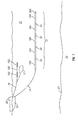
- FIG. 1 shows an example embodiment of a marine electromagnetic survey system using sensor cables according to the invention.
- FIG. 2 shows an example embodiment of sensor cable segments having reversible wiring to electrodes disposed on the surface of the segment.
- FIG. 3 shows an example embodiment of a signal processing module.
- FIG. 4 shows a power circuit that may be used in some embodiments of a module according to FIG. 3 .
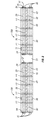
- FIG. 5 shows an example embodiment of interconnected sensor cable segments.
- the electromagnetic survey system includes a sensor cable 10 that may be assembled from a plurality of cable segments 10A, signal processing modules ("modules") 50 and an end plug 50A at the aft end (with respect to towing direction) of the sensor cable 10.
- the cable segments 10A will be explained in more detail below with reference to FIG. 2 .
- Some of the modules 50 may include various interconnection and signal processing circuits as will be explained with reference to FIG. 3 .
- the sensor cable 10 is shown being towed at the end of a tow cable 14 by a survey vessel 18 moving on the surface of a body of water 11 such as a lake or an ocean.
- the sensor cable 10 may alternatively be deployed on the water bottom 23.
- the end plug 50A may be provided in some embodiments to exclude water from entering an exposed termination (explained with reference to FIG. 2 ) at the aft end of the aftmost cable segment 10A or module 50.
- the end plug 50A need not include any electrical or optical circuitry therein.
- the vessel 18 may include thereon equipment, shown generally at 20 and referred to for convenience as a "recording system” that may include devices (none shown separately) for navigation, energizing electrodes or antennas for imparting an electromagnetic field in the formations 24 below the water bottom 23, and for recording and processing signals generated by the various sensors ( FIG. 2 ) on the sensor cable 10.
- a recording system may include devices (none shown separately) for navigation, energizing electrodes or antennas for imparting an electromagnetic field in the formations 24 below the water bottom 23, and for recording and processing signals generated by the various sensors ( FIG. 2 ) on the sensor cable 10.
- the electromagnetic survey system shown in FIG. 1 may include an electromagnetic source cable 16 for inducing an electromagnetic field in the formations below the water bottom 23.
- the source cable 16 may consist of a tow cable coupled to the vessel 18 and including insulated electrical conductors (not shown) and a strength member (not shown separately) to transmit axial towing force from the vessel 18.
- the aft end (with respect to towing direction) of the tow cable may be coupled to one end of a first electrode cable 16A.
- the aft end of the first electrode cable 16A may be coupled to a spacer rope or cable 16C.
- the aft end of the spacer rope or cable 16C may be coupled to the forward end (with respect to towing direction) of a second electrode cable 16B.
- the source cable 16 may be towed by the survey vessel 18 or by a different vessel (not shown).
- the electrode cables 16A, 16B may be energized at selected times by an electrical current source (not shown separately) in the recording system 20 or in other equipment (not shown) so as to induce a time varying electromagnetic field in the formations below the water bottom 23.
- the current may be alternating current or switched direct current (e.g., switching current on, switching current off, reversing current polarity, or sequential switching such as a pseudorandom binary sequence).
- the configuration shown in FIG. 1 induces a horizontal dipole electric field in the subsurface when the electrodes 16A, 16B are energized by the electric current.
- the type of current used to energize the electrodes is not limited to the foregoing as the invention is applicable to use with both frequency domain (continuous output and transient induced electromagnetic fields.
- the electric current may be passed through a wire loop or coil 17 towed by the source cable 16. Electric current as explained above so passed through the coil 17 will induce a time varying magnetic field, and thus an electromagnetic field, in the water 11 and the formations 24 below the water bottom.
- a sensor cable segment 10A may include a water resistant, electrically non-conductive jacket 30 such as may be made from polyurethane or similar plastic.
- the jacket 30 may extend the entire length of the segment 10A.
- a termination plate 34 may be disposed at longitudinal ends of the segment 10A.
- the termination plate 34 may be configured to sealingly engage the interior surface of the end of the jacket 30, and may include electrical connectors 35 therein for making electrical connection to an adjacent sensor cable segment 10A or to an electronic module 50.
- Example circuitry for one or more modules 50 will be further explained with reference to FIG. 3 .
- the segment 10A may include one or more strength members 32 disposed inside the jacket 30 and coupled at the longitudinal ends thereof to a respective termination plate 34. Axial loading during towing the sensor cable (10 in FIG. 1 ) through the water may be carried by the strength member 32, which may be made, for example, from natural or synthetic fiber rope.
- Each sensor cable segment 10A may include disposed on an exterior surface of the jacket 30 a plurality of spaced apart electrodes E1, E2, E3, E4.
- the electrodes E1, E2, E3 E4 may be arranged on the jacket 30 to be in contact with the water, and may be sealingly engaged to the jacket 30 to resist intrusion of water into the interior of the jacket 30.
- the electrodes E1, E2, E3, E4 may be any electrode structure known in the art for use with electromagnetic sensing cables or sensor cables.
- Each electrode E1, E2, E3, E4 may be electrically coupled to a respective electrical conductor 36, 38, 40, 42 disposed inside the jacket 30 and terminated at each longitudinal end in one of the electrical connectors 35 in each termination plate 34.
- the electrical conductors 36, 38, 40, 42 may extend and connect to the electrical connectors 35 in each termination plate 34 so that electrical connection to each electrode E1, E2, E3, E4 may be possible at each end of the sensor cable segment 10A.
- the electrical connectors 35 in each termination plate 34 may be hermaphroditic so that the segment 10A may be coupled in a sensor cable (10 in FIG. 1 ) in either longitudinal direction and provide the same electrical connections to the respective electrodes E1, E2, E3, E4. It should be noted that using such hermaphroditic connectors is optional. While the example embodiment of the sensor cable segment 10A shown in FIG. 2 includes four electrodes and four corresponding electrical conductors, it should be clearly understood that any convenient number of electrodes and corresponding electrical conductors may be used in other embodiments without exceeding the scope of the present invention.
- the sensor cable segment 10A may include one or more buoyancy spacers 31.
- Such spacers 31 may be made from foamed polypropylene so as to be substantially rigid, yet provide buoyancy to the sensor cable segment 10A.
- the number of buoyancy spacers will depend on the weight in water of the other components of the sensor cable segment 10A and the desired buoyancy for the sensor cable segment 10.
- some embodiments of the sensor cable segment 10A may include one or more optical fibers 39 extending inside the jacket 30 from one termination plate 34 to the other and may be terminated therein by suitable optical connectors 37.
- the optical fiber(s) 39 may be used in some embodiments to communicate signals, for example, commands from the recording unit (20 in FIG. 1 ) and data to the recording unit (20 in FIG. 1 ) to and from the various modules 50 without generating electrical interference.
- Void space in the interior of the jacket 30 may be filled with a buoyancy void filler 46, such as may be made from a polymerizing agent dispersed in oil or kerosene. Such material may be introduced into the interior of the jacket 30 in liquid form and may subsequently change state to semi-solid, such as a gel. Such material may further resist entry of water into the interior of the jacket 30 and may reduce the possibility of leakage of hazardous material into the water in the event the jacket 30 becomes damaged. Such materials are known in the art to be used in making seismic sensor streamers.
- the two sensor cable segments 10A in FIG. 2 are shown coupled to opposite ends of one of the signal processing modules 50.
- the signal processing modules 50 may each have a housing 52 made from a high strength, preferably nonmagnetic material, for example, titanium, stainless steel or high strength plastic.
- the signal processing modules 50 may include terminations (see FIG. 2 ) on both longitudinal ends that each may make both mechanical and electrical and/or optical connection to the termination plate (34 in FIG. 2 ) at one end of one of the sensor cable segments (10A in FIG. 2 ).
- the housing 52 and terminations may be configured to exclude water entry from an interior space inside the housing 52.
- the electrical conductors 36, 38, 40, 42 may be coupled to a multi-pole switch, which in the present example embodiment may be an eight-pole switch 54.
- the eight-pole switch 54 enables selected ones of the electrodes (E1, E2, E3, E4 in FIG. 2 ) to be electrically coupled to input terminals of one or more low noise amplifiers 56.
- the combination of switch 54 (and/or multiplexer) and low noise amplifiers 56 enables electric potential signals from any selected pair of electrodes in the two sensor cable segments (10A in FIG. 2 ) to be measured.
- the signals measured may be voltage related to the amplitude of the electric field between the selected electrodes (i.e., the circuits are arranged such that the selected electrodes are coupled across the input to a voltage measuring circuit).
- Measurement may be made using a mixed signal device such as a combined analog to digital converter, programmer, data storage and controller (“controller”), shown at 58 in FIG. 3 .
- controller data storage and controller
- Such devices are known in the art and may be application specific integrated circuits, or combinations of circuit elements to perform substantially the same functions.
- the controller 58 may also include internal or external circuitry (not shown separately) to convert electrical signals to optical signals.
- Optical signals may be communicated to the recording unit (20 in FIG. 1 ) and/or to other ones of the signal processing modules 50 in the sensor cable (10 in FIG. 1 ). Using optical signal communication between signal processing modules and between the recording unit (20 in FIG. 1 ) and the signal processing modules 50 may reduce any noise introduced into the electrical field measurements made between selected pairs of the electrodes.
- switch 54 may be comprise an exchangeable fixed wiring implemented before survey operations begin, or alternatively switch 54 may comprise a software controlled electronic switch to provide dynamic switching during survey operations (e.g., while towing the marine electromagnetic sensor cable system through the body of water).
- Some embodiments of the signal processing module 50 may omit the multi-pole switch 54 or equivalent multiplexer and switch combination and include only one or more low noise amplifier 56.
- the inputs to the low noise amplifier 56 may be made directly to selected ones of the electrical conductors 36, 38, 40, 42 depending on the desired electrical configuration of the sensor cable (10 in FIG. 1 ).
- Potential signals measured between selected pairs of the electrodes in two sensor cable segments 10A interconnected by a signal processing module 50 may be combined with measurements made and/or stored in different signal processing modules (50 in FIG. 1 ) to synthesize signal measurements corresponding to any selected pair of electrodes by communicating signals optically (or electrically) between signal processing modules 50.
- each signal processing module 50 may include a relay K, a power conditioner 60 and a battery 62 or other electrical energy storage device.
- the battery 62 may be used to operate the electrical circuitry in each signal processing module 50 as described with reference to FIG. 3 .
- each sensor cable segment 10A may include power conductors 64 ultimately coupled to an electric power source, such as high voltage AC or DC, in the recording unit (20 in FIG. 1 ). In the present embodiment, during survey operations, the power conductors will typically not be energized.
- each relay K is in its normally open position. In such position, connections between signal processing modules 50 of the power conductors are opened, so that no inductive loops are formed by the power conductors 64. Between surveys, the power conductors 64 may be energized. By energizing the power conductors 64 all the relays K move to their normally closed position. Electrical power is thereby conducted to the power conditioner 60 in each signal processing module 50 to charge the respective battery 62 therein for continued surveying operations.
- each sensor cable segment 10A may include a selected number of electrodes E, for example, two.
- Each sensor cable segment 10A(i)-10A(v) may include a selected number of electrical conductors extending the length of the entire sensor cable segment 10A, for example, four, so that electrical connection to each electrode E may be made from either end of the sensor cable segment 10A.
- the example in FIG. 5 shows the tow cable 14 connected to a first signal processing module 50.
- a first sensor cable segment 10A(i) as explained with reference to FIG. 2 may be connected to the first signal processing module 50 connected to the end of the tow cable.
- a second signal processing module 50 may be connected to the other end of the first sensor cable segment 10A(i).
- One or more additional sensor cable segments 10A(ii)-10A(iii) may be connected end to end as shown, and then connected to a third signal processing module 50. Internal through wiring may be provided such that in some example embodiments, the direction of the sensor cable segment as it is connected to adjacent components may be made in either axial direction (although this is not a requirement of the invention).
- Using a configuration such as shown in FIG. 5 it may be possible to connect sensor cable segments in such manner as to obtain a selected distance between pairs of electrodes connected to the circuits in the signal processing modules 50, for example, there may be an increasing distance between electrodes (E1 through E4 in FIG. 2 ) with respect to offset (distance between the selected electrode pairs and the source (16A, 16B and/or 17 in FIG. 1 ).
- each sensor cable segment 10A(i)-10A(v) includes two electrodes E1-E2 and four electrical conductors.
- the potential between a first electrode and a second electrode measured at each signal processing module on each electrical conductor is illustrated as follows: First Electrode Second Electrode Voltage E1 10A(i) E2 10A(i) V11 E1 10A(i) E1 10A(ii) V21 E1 10A(ii) E1 10A(iv) V31 E2 10A(i) E2 10A(ii) V22 E2 10A(ii) E2 10A(iv) V32 E2 10A(i) E1 10A(iii) V23 E1 10A(iii) E1 10A(v) V33 E2 10A(i) E2 10A(iii) V24 E2 10A(iii) E2 10A(v) V34
- These voltages may be combined to synthesize voltage measurements between additional electrode pairs.
- the voltage between electrode E1 on sensor cable segment 10A(i) and electrode E2 on sensor cable segment 10A(iii) may be synthesized by the addition of V11 and V24.
- a "sensor cable subsystem” may include a signal processing module 50 coupled to one or more sensor cable segments 10A which are coupled together at longitudinal ends.
- FIG. 2 shows a single sensor cable subsystem coupled to a second sensor cable segment
- FIG. 5 shows three sensor cable subsystems coupled together.
- the circuitry of a sensor cable subsystem is configured to allow measurement of electric potential signals by signal processing module 50 between any selected pair of electrodes disposed on any of the sensor cable segments in the sensor cable subsystem.
- a sensor cable such as shown in FIG.
- a plurality of such sensor cable subsystems may be connected end to end as shown, with a forward end (with respect to towing direction) of the plurality of subsystems connected to a cable from the survey vessel (18 in FIG. 1 ) or other tow vessel.
- the aft end (with respect to towing direction) of the interconnected subsystems may include an end plug 50A.
- the switch (54 in FIG. 3 ) in each signal processing module 50 may be configured so that electrical voltage signals may be measured across any selected pair of electrodes disposed on any of the sensor cable segments in the receiver sensor cable. In some embodiments, only a single sensor cable subsystem may be used.
- the aft end of the single sensor cable subsystem in such embodiments may be coupled to an end plug (50A in FIG. 1 ) as explained above.
- terminals from the switch (54 in FIG. 3 ) that would otherwise be connected to an aft sensor cable segment may remain unconnected.
- An electromagnetic sensor cable made according to the invention may provide a high degree of flexibility in selecting electrode spacing for measuring electric potential components in an induced electromagnetic field, so that, for example, electrode spacing for individual measurements may be selectively related to offset, while simplifying and standardizing construction of sensor cable segments and signal processing modules.
Landscapes
- Physics & Mathematics (AREA)
- Life Sciences & Earth Sciences (AREA)
- Engineering & Computer Science (AREA)
- Remote Sensing (AREA)
- Electromagnetism (AREA)
- Environmental & Geological Engineering (AREA)
- Geology (AREA)
- General Life Sciences & Earth Sciences (AREA)
- General Physics & Mathematics (AREA)
- Geophysics (AREA)
- Acoustics & Sound (AREA)
- Investigating Or Analyzing Materials By The Use Of Electric Means (AREA)
Applications Claiming Priority (1)
| Application Number | Priority Date | Filing Date | Title |
|---|---|---|---|
| US13/276,766 US8816690B2 (en) | 2011-11-21 | 2011-11-21 | Electromagnetic sensor cable and electrical configuration therefor |
Publications (3)
| Publication Number | Publication Date |
|---|---|
| EP2594966A2 true EP2594966A2 (de) | 2013-05-22 |
| EP2594966A3 EP2594966A3 (de) | 2014-10-15 |
| EP2594966B1 EP2594966B1 (de) | 2020-01-08 |
Family
ID=47263118
Family Applications (1)
| Application Number | Title | Priority Date | Filing Date |
|---|---|---|---|
| EP12193665.2A Active EP2594966B1 (de) | 2011-11-21 | 2012-11-21 | Elektromagnetisches Sensorkabel und elektrische Konfiguration dafür |
Country Status (2)
| Country | Link |
|---|---|
| US (1) | US8816690B2 (de) |
| EP (1) | EP2594966B1 (de) |
Cited By (2)
| Publication number | Priority date | Publication date | Assignee | Title |
|---|---|---|---|---|
| CN103616728A (zh) * | 2013-11-15 | 2014-03-05 | 中航光电科技股份有限公司 | 一种有水信号传感器 |
| CN104849818A (zh) * | 2014-02-18 | 2015-08-19 | Pgs地球物理公司 | 具有可浸没光纤管道的海底电缆 |
Families Citing this family (15)
| Publication number | Priority date | Publication date | Assignee | Title |
|---|---|---|---|---|
| US10598810B2 (en) | 2014-05-19 | 2020-03-24 | Halliburton Energy Services, Inc. | Optical magnetic field sensor units for a downhole environment |
| US10012751B2 (en) | 2014-06-18 | 2018-07-03 | Pgs Geophysical As | Electrode adapter for geophysical surveys |
| US10605947B2 (en) * | 2014-06-18 | 2020-03-31 | Pgs Geophysical As | Marine streamer connector used as an electrode |
| US10042073B2 (en) * | 2014-10-17 | 2018-08-07 | Pgs Geophysical As | Electrically isolated streamer section |
| US10302796B2 (en) | 2014-11-26 | 2019-05-28 | Halliburton Energy Services, Inc. | Onshore electromagnetic reservoir monitoring |
| US9910063B2 (en) * | 2015-04-21 | 2018-03-06 | Pgs Geophysical As | Magnetometer as an orientation sensor |
| US10133017B2 (en) * | 2015-08-07 | 2018-11-20 | Pgs Geophysical As | Vented optical tube |
| US10175277B2 (en) | 2015-08-31 | 2019-01-08 | Pgs Geophysical As | Identification of degrading electrodes in a marine electromagnetic survey system |
| US10838096B2 (en) | 2016-12-13 | 2020-11-17 | Pgs Geophysical As | Method and apparatus for dynamic roll compensation of streamer for marine geophysical surveying |
| US10795043B2 (en) * | 2017-02-28 | 2020-10-06 | Pgs Geophysical As | Towable electromagnetic source equipment |
| BR112020011834B1 (pt) | 2017-12-15 | 2023-12-05 | Pgs Geophysical As | Medição de pressão e aceleração sísmica |
| WO2019234222A1 (en) | 2018-06-08 | 2019-12-12 | Pgs Geophysical As | Linear array of piezoelectric transducers for towed marine streamers |
| CN112285543B (zh) * | 2020-09-18 | 2023-03-07 | 昆明理工大学 | 一种基于交流电信号传输的铅鱼水下信号采集装置 |
| CN114325842B (zh) * | 2021-11-25 | 2025-12-23 | 宜昌测试技术研究所 | 一种座底式电磁侦测系统 |
| US12461265B2 (en) | 2021-12-16 | 2025-11-04 | Pgs Geophysical As | Seismic data acquisition with extended dynamic range |
Family Cites Families (15)
| Publication number | Priority date | Publication date | Assignee | Title |
|---|---|---|---|---|
| US4617518A (en) | 1983-11-21 | 1986-10-14 | Exxon Production Research Co. | Method and apparatus for offshore electromagnetic sounding utilizing wavelength effects to determine optimum source and detector positions |
| US5627798A (en) | 1995-05-05 | 1997-05-06 | I/O Exploration Products (U.S.A.), Inc. | Hierarchical telemetry system for seismic acquisition |
| NO326506B1 (no) | 2003-07-10 | 2008-12-15 | Norsk Hydro As | Et maringeofysisk innsamlingssystem med en kabel med seismiske kilder og mottakere og elektromagnteiske kilder og mottakere |
| US7132831B2 (en) | 2004-03-31 | 2006-11-07 | Peteralv Brabers | Electrode configuration for resistivity sounding |
| US7139217B2 (en) | 2004-05-27 | 2006-11-21 | Pgs Americas, Inc. | Water bottom cable seismic survey cable and system |
| US7737698B2 (en) | 2006-03-29 | 2010-06-15 | Pgs Geophysical As | Low noise, towed electromagnetic system for subsurface exploration |
| US7602191B2 (en) | 2007-06-29 | 2009-10-13 | Pgs Geophysical As | Cable-type electromagnetic receiver system for subsurface exploration |
| US7446535B1 (en) | 2007-09-21 | 2008-11-04 | Pgs Geopysical As | Electrode structure and streamer made therewith for marine electromagnetic surveying |
| US7671598B2 (en) | 2007-12-03 | 2010-03-02 | Pgs Geophysical As | Method and apparatus for reducing induction noise in measurements made with a towed electromagnetic survey system |
| US7834632B2 (en) | 2007-12-03 | 2010-11-16 | Pgs Geophysical As | Receiver streamer system and method for marine electromagnetic surveying |
| NO332562B1 (no) * | 2008-07-04 | 2012-10-29 | Multifield Geophysics As | Marinseismisk og elektromagnetisk streamerkabel |
| US20100045296A1 (en) | 2008-08-19 | 2010-02-25 | Pgs Geophysical As | Cable system for marine data acquisition |
| US20110260730A1 (en) * | 2010-04-27 | 2011-10-27 | Suedow Gustav Goeran Mattias | Switchable front-end measurement unit for towed marine electromagnetic survey cables |
| US8896314B2 (en) | 2010-05-05 | 2014-11-25 | Pgs Geophysical As | Multiple component electromagnetic survey signal acquisition method |
| US8710845B2 (en) * | 2011-09-19 | 2014-04-29 | Pgs Geophysical As | Electromagnetic sensor cable and electrical configuration therefor |
-
2011
- 2011-11-21 US US13/276,766 patent/US8816690B2/en active Active
-
2012
- 2012-11-21 EP EP12193665.2A patent/EP2594966B1/de active Active
Non-Patent Citations (1)
| Title |
|---|
| None |
Cited By (5)
| Publication number | Priority date | Publication date | Assignee | Title |
|---|---|---|---|---|
| CN103616728A (zh) * | 2013-11-15 | 2014-03-05 | 中航光电科技股份有限公司 | 一种有水信号传感器 |
| CN103616728B (zh) * | 2013-11-15 | 2016-08-10 | 中航光电科技股份有限公司 | 一种有水信号传感器 |
| CN104849818A (zh) * | 2014-02-18 | 2015-08-19 | Pgs地球物理公司 | 具有可浸没光纤管道的海底电缆 |
| EP2908162A1 (de) * | 2014-02-18 | 2015-08-19 | PGS Geophysical AS | Unterwasserkabel mit flutbarer faseroptischer Leitung |
| US10175437B2 (en) | 2014-02-18 | 2019-01-08 | Pgs Geophysical As | Subsea cable having floodable optical fiber conduit |
Also Published As
| Publication number | Publication date |
|---|---|
| EP2594966B1 (de) | 2020-01-08 |
| US20130127471A1 (en) | 2013-05-23 |
| EP2594966A3 (de) | 2014-10-15 |
| US8816690B2 (en) | 2014-08-26 |
Similar Documents
| Publication | Publication Date | Title |
|---|---|---|
| EP2594966B1 (de) | Elektromagnetisches Sensorkabel und elektrische Konfiguration dafür | |
| EP2174167B1 (de) | Kabel und system für elektromagnetische meeresmessung | |
| EP2230535B1 (de) | Verfahren und System zur Kalibrierung von Streamer-Elektroden in einem marinen elektromagnetischen Vermessungssystem | |
| US8810248B2 (en) | Method of testing electric field recording of a marine electromagnetic sensor cable | |
| US9459368B2 (en) | Acquisition system and method for towed electromagnetic sensor cable and source | |
| AU2011201226B2 (en) | Method for 2D and 3D electromagnetic field measurements using a towed marine electromagnetic survey system | |
| AU2010200019B8 (en) | Combined electromagnetic and seismic acquisition system | |
| US20110260730A1 (en) | Switchable front-end measurement unit for towed marine electromagnetic survey cables | |
| EA012766B1 (ru) | Малошумная буксируемая электромагнитная система для подземных геологических исследований | |
| US9778036B2 (en) | Switchable front-end measurement unit for towed marine electromagnetic streamer cables | |
| GB2494759A (en) | Electromagnetic sensor cable and electrical configuration therefor | |
| EP3009865B1 (de) | Elektrisch isolierter streamerabschnitt | |
| WO2012036559A1 (en) | E-field sensor for marine streaming |
Legal Events
| Date | Code | Title | Description |
|---|---|---|---|
| PUAI | Public reference made under article 153(3) epc to a published international application that has entered the european phase |
Free format text: ORIGINAL CODE: 0009012 |
|
| AK | Designated contracting states |
Kind code of ref document: A2 Designated state(s): AL AT BE BG CH CY CZ DE DK EE ES FI FR GB GR HR HU IE IS IT LI LT LU LV MC MK MT NL NO PL PT RO RS SE SI SK SM TR |
|
| AX | Request for extension of the european patent |
Extension state: BA ME |
|
| RIN1 | Information on inventor provided before grant (corrected) |
Inventor name: LINDQVIST, ULF PETER Inventor name: JUHASZ, ANDRAS ROBERT Inventor name: FERNIHOUGH, ROBERT Inventor name: MATTIAS SUEDOW, GUSTAV GOERAN |
|
| RAP1 | Party data changed (applicant data changed or rights of an application transferred) |
Owner name: PGS GEOPHYSICAL AS |
|
| PUAL | Search report despatched |
Free format text: ORIGINAL CODE: 0009013 |
|
| AK | Designated contracting states |
Kind code of ref document: A3 Designated state(s): AL AT BE BG CH CY CZ DE DK EE ES FI FR GB GR HR HU IE IS IT LI LT LU LV MC MK MT NL NO PL PT RO RS SE SI SK SM TR |
|
| AX | Request for extension of the european patent |
Extension state: BA ME |
|
| RIC1 | Information provided on ipc code assigned before grant |
Ipc: G01V 3/08 20060101AFI20140909BHEP Ipc: G01V 1/20 20060101ALI20140909BHEP Ipc: G01V 3/12 20060101ALI20140909BHEP |
|
| 17P | Request for examination filed |
Effective date: 20150219 |
|
| RBV | Designated contracting states (corrected) |
Designated state(s): AL AT BE BG CH CY CZ DE DK EE ES FI FR GB GR HR HU IE IS IT LI LT LU LV MC MK MT NL NO PL PT RO RS SE SI SK SM TR |
|
| STAA | Information on the status of an ep patent application or granted ep patent |
Free format text: STATUS: EXAMINATION IS IN PROGRESS |
|
| 17Q | First examination report despatched |
Effective date: 20180718 |
|
| GRAP | Despatch of communication of intention to grant a patent |
Free format text: ORIGINAL CODE: EPIDOSNIGR1 |
|
| STAA | Information on the status of an ep patent application or granted ep patent |
Free format text: STATUS: GRANT OF PATENT IS INTENDED |
|
| INTG | Intention to grant announced |
Effective date: 20190619 |
|
| GRAS | Grant fee paid |
Free format text: ORIGINAL CODE: EPIDOSNIGR3 |
|
| GRAA | (expected) grant |
Free format text: ORIGINAL CODE: 0009210 |
|
| STAA | Information on the status of an ep patent application or granted ep patent |
Free format text: STATUS: THE PATENT HAS BEEN GRANTED |
|
| AK | Designated contracting states |
Kind code of ref document: B1 Designated state(s): AL AT BE BG CH CY CZ DE DK EE ES FI FR GB GR HR HU IE IS IT LI LT LU LV MC MK MT NL NO PL PT RO RS SE SI SK SM TR |
|
| REG | Reference to a national code |
Ref country code: GB Ref legal event code: FG4D |
|
| REG | Reference to a national code |
Ref country code: CH Ref legal event code: EP |
|
| REG | Reference to a national code |
Ref country code: DE Ref legal event code: R096 Ref document number: 602012067068 Country of ref document: DE |
|
| REG | Reference to a national code |
Ref country code: IE Ref legal event code: FG4D |
|
| REG | Reference to a national code |
Ref country code: AT Ref legal event code: REF Ref document number: 1223388 Country of ref document: AT Kind code of ref document: T Effective date: 20200215 |
|
| REG | Reference to a national code |
Ref country code: NO Ref legal event code: T2 Effective date: 20200108 |
|
| REG | Reference to a national code |
Ref country code: NL Ref legal event code: MP Effective date: 20200108 |
|
| REG | Reference to a national code |
Ref country code: LT Ref legal event code: MG4D |
|
| PG25 | Lapsed in a contracting state [announced via postgrant information from national office to epo] |
Ref country code: RS Free format text: LAPSE BECAUSE OF FAILURE TO SUBMIT A TRANSLATION OF THE DESCRIPTION OR TO PAY THE FEE WITHIN THE PRESCRIBED TIME-LIMIT Effective date: 20200108 Ref country code: NL Free format text: LAPSE BECAUSE OF FAILURE TO SUBMIT A TRANSLATION OF THE DESCRIPTION OR TO PAY THE FEE WITHIN THE PRESCRIBED TIME-LIMIT Effective date: 20200108 Ref country code: LT Free format text: LAPSE BECAUSE OF FAILURE TO SUBMIT A TRANSLATION OF THE DESCRIPTION OR TO PAY THE FEE WITHIN THE PRESCRIBED TIME-LIMIT Effective date: 20200108 Ref country code: PT Free format text: LAPSE BECAUSE OF FAILURE TO SUBMIT A TRANSLATION OF THE DESCRIPTION OR TO PAY THE FEE WITHIN THE PRESCRIBED TIME-LIMIT Effective date: 20200531 Ref country code: FI Free format text: LAPSE BECAUSE OF FAILURE TO SUBMIT A TRANSLATION OF THE DESCRIPTION OR TO PAY THE FEE WITHIN THE PRESCRIBED TIME-LIMIT Effective date: 20200108 |
|
| PG25 | Lapsed in a contracting state [announced via postgrant information from national office to epo] |
Ref country code: SE Free format text: LAPSE BECAUSE OF FAILURE TO SUBMIT A TRANSLATION OF THE DESCRIPTION OR TO PAY THE FEE WITHIN THE PRESCRIBED TIME-LIMIT Effective date: 20200108 Ref country code: LV Free format text: LAPSE BECAUSE OF FAILURE TO SUBMIT A TRANSLATION OF THE DESCRIPTION OR TO PAY THE FEE WITHIN THE PRESCRIBED TIME-LIMIT Effective date: 20200108 Ref country code: IS Free format text: LAPSE BECAUSE OF FAILURE TO SUBMIT A TRANSLATION OF THE DESCRIPTION OR TO PAY THE FEE WITHIN THE PRESCRIBED TIME-LIMIT Effective date: 20200508 Ref country code: BG Free format text: LAPSE BECAUSE OF FAILURE TO SUBMIT A TRANSLATION OF THE DESCRIPTION OR TO PAY THE FEE WITHIN THE PRESCRIBED TIME-LIMIT Effective date: 20200408 Ref country code: HR Free format text: LAPSE BECAUSE OF FAILURE TO SUBMIT A TRANSLATION OF THE DESCRIPTION OR TO PAY THE FEE WITHIN THE PRESCRIBED TIME-LIMIT Effective date: 20200108 Ref country code: GR Free format text: LAPSE BECAUSE OF FAILURE TO SUBMIT A TRANSLATION OF THE DESCRIPTION OR TO PAY THE FEE WITHIN THE PRESCRIBED TIME-LIMIT Effective date: 20200409 |
|
| REG | Reference to a national code |
Ref country code: DE Ref legal event code: R097 Ref document number: 602012067068 Country of ref document: DE |
|
| PG25 | Lapsed in a contracting state [announced via postgrant information from national office to epo] |
Ref country code: RO Free format text: LAPSE BECAUSE OF FAILURE TO SUBMIT A TRANSLATION OF THE DESCRIPTION OR TO PAY THE FEE WITHIN THE PRESCRIBED TIME-LIMIT Effective date: 20200108 Ref country code: CZ Free format text: LAPSE BECAUSE OF FAILURE TO SUBMIT A TRANSLATION OF THE DESCRIPTION OR TO PAY THE FEE WITHIN THE PRESCRIBED TIME-LIMIT Effective date: 20200108 Ref country code: SK Free format text: LAPSE BECAUSE OF FAILURE TO SUBMIT A TRANSLATION OF THE DESCRIPTION OR TO PAY THE FEE WITHIN THE PRESCRIBED TIME-LIMIT Effective date: 20200108 Ref country code: EE Free format text: LAPSE BECAUSE OF FAILURE TO SUBMIT A TRANSLATION OF THE DESCRIPTION OR TO PAY THE FEE WITHIN THE PRESCRIBED TIME-LIMIT Effective date: 20200108 Ref country code: SM Free format text: LAPSE BECAUSE OF FAILURE TO SUBMIT A TRANSLATION OF THE DESCRIPTION OR TO PAY THE FEE WITHIN THE PRESCRIBED TIME-LIMIT Effective date: 20200108 Ref country code: DK Free format text: LAPSE BECAUSE OF FAILURE TO SUBMIT A TRANSLATION OF THE DESCRIPTION OR TO PAY THE FEE WITHIN THE PRESCRIBED TIME-LIMIT Effective date: 20200108 Ref country code: ES Free format text: LAPSE BECAUSE OF FAILURE TO SUBMIT A TRANSLATION OF THE DESCRIPTION OR TO PAY THE FEE WITHIN THE PRESCRIBED TIME-LIMIT Effective date: 20200108 |
|
| PLBE | No opposition filed within time limit |
Free format text: ORIGINAL CODE: 0009261 |
|
| STAA | Information on the status of an ep patent application or granted ep patent |
Free format text: STATUS: NO OPPOSITION FILED WITHIN TIME LIMIT |
|
| REG | Reference to a national code |
Ref country code: AT Ref legal event code: MK05 Ref document number: 1223388 Country of ref document: AT Kind code of ref document: T Effective date: 20200108 |
|
| 26N | No opposition filed |
Effective date: 20201009 |
|
| PG25 | Lapsed in a contracting state [announced via postgrant information from national office to epo] |
Ref country code: AT Free format text: LAPSE BECAUSE OF FAILURE TO SUBMIT A TRANSLATION OF THE DESCRIPTION OR TO PAY THE FEE WITHIN THE PRESCRIBED TIME-LIMIT Effective date: 20200108 Ref country code: IT Free format text: LAPSE BECAUSE OF FAILURE TO SUBMIT A TRANSLATION OF THE DESCRIPTION OR TO PAY THE FEE WITHIN THE PRESCRIBED TIME-LIMIT Effective date: 20200108 |
|
| PG25 | Lapsed in a contracting state [announced via postgrant information from national office to epo] |
Ref country code: SI Free format text: LAPSE BECAUSE OF FAILURE TO SUBMIT A TRANSLATION OF THE DESCRIPTION OR TO PAY THE FEE WITHIN THE PRESCRIBED TIME-LIMIT Effective date: 20200108 Ref country code: PL Free format text: LAPSE BECAUSE OF FAILURE TO SUBMIT A TRANSLATION OF THE DESCRIPTION OR TO PAY THE FEE WITHIN THE PRESCRIBED TIME-LIMIT Effective date: 20200108 |
|
| REG | Reference to a national code |
Ref country code: DE Ref legal event code: R119 Ref document number: 602012067068 Country of ref document: DE |
|
| PG25 | Lapsed in a contracting state [announced via postgrant information from national office to epo] |
Ref country code: MC Free format text: LAPSE BECAUSE OF FAILURE TO SUBMIT A TRANSLATION OF THE DESCRIPTION OR TO PAY THE FEE WITHIN THE PRESCRIBED TIME-LIMIT Effective date: 20200108 |
|
| REG | Reference to a national code |
Ref country code: CH Ref legal event code: PL |
|
| PG25 | Lapsed in a contracting state [announced via postgrant information from national office to epo] |
Ref country code: LU Free format text: LAPSE BECAUSE OF NON-PAYMENT OF DUE FEES Effective date: 20201121 |
|
| REG | Reference to a national code |
Ref country code: BE Ref legal event code: MM Effective date: 20201130 |
|
| PG25 | Lapsed in a contracting state [announced via postgrant information from national office to epo] |
Ref country code: CH Free format text: LAPSE BECAUSE OF NON-PAYMENT OF DUE FEES Effective date: 20201130 Ref country code: LI Free format text: LAPSE BECAUSE OF NON-PAYMENT OF DUE FEES Effective date: 20201130 |
|
| PG25 | Lapsed in a contracting state [announced via postgrant information from national office to epo] |
Ref country code: IE Free format text: LAPSE BECAUSE OF NON-PAYMENT OF DUE FEES Effective date: 20201121 |
|
| PG25 | Lapsed in a contracting state [announced via postgrant information from national office to epo] |
Ref country code: DE Free format text: LAPSE BECAUSE OF NON-PAYMENT OF DUE FEES Effective date: 20210601 |
|
| PGFP | Annual fee paid to national office [announced via postgrant information from national office to epo] |
Ref country code: GB Payment date: 20211129 Year of fee payment: 10 Ref country code: NO Payment date: 20211126 Year of fee payment: 10 Ref country code: FR Payment date: 20211124 Year of fee payment: 10 |
|
| PG25 | Lapsed in a contracting state [announced via postgrant information from national office to epo] |
Ref country code: TR Free format text: LAPSE BECAUSE OF FAILURE TO SUBMIT A TRANSLATION OF THE DESCRIPTION OR TO PAY THE FEE WITHIN THE PRESCRIBED TIME-LIMIT Effective date: 20200108 Ref country code: MT Free format text: LAPSE BECAUSE OF FAILURE TO SUBMIT A TRANSLATION OF THE DESCRIPTION OR TO PAY THE FEE WITHIN THE PRESCRIBED TIME-LIMIT Effective date: 20200108 Ref country code: CY Free format text: LAPSE BECAUSE OF FAILURE TO SUBMIT A TRANSLATION OF THE DESCRIPTION OR TO PAY THE FEE WITHIN THE PRESCRIBED TIME-LIMIT Effective date: 20200108 |
|
| PG25 | Lapsed in a contracting state [announced via postgrant information from national office to epo] |
Ref country code: MK Free format text: LAPSE BECAUSE OF FAILURE TO SUBMIT A TRANSLATION OF THE DESCRIPTION OR TO PAY THE FEE WITHIN THE PRESCRIBED TIME-LIMIT Effective date: 20200108 Ref country code: AL Free format text: LAPSE BECAUSE OF FAILURE TO SUBMIT A TRANSLATION OF THE DESCRIPTION OR TO PAY THE FEE WITHIN THE PRESCRIBED TIME-LIMIT Effective date: 20200108 |
|
| PG25 | Lapsed in a contracting state [announced via postgrant information from national office to epo] |
Ref country code: BE Free format text: LAPSE BECAUSE OF NON-PAYMENT OF DUE FEES Effective date: 20201130 |
|
| REG | Reference to a national code |
Ref country code: NO Ref legal event code: MMEP |
|
| GBPC | Gb: european patent ceased through non-payment of renewal fee |
Effective date: 20221121 |
|
| PG25 | Lapsed in a contracting state [announced via postgrant information from national office to epo] |
Ref country code: NO Free format text: LAPSE BECAUSE OF NON-PAYMENT OF DUE FEES Effective date: 20221130 |
|
| PG25 | Lapsed in a contracting state [announced via postgrant information from national office to epo] |
Ref country code: GB Free format text: LAPSE BECAUSE OF NON-PAYMENT OF DUE FEES Effective date: 20221121 |
|
| PG25 | Lapsed in a contracting state [announced via postgrant information from national office to epo] |
Ref country code: FR Free format text: LAPSE BECAUSE OF NON-PAYMENT OF DUE FEES Effective date: 20221130 |