EP2594945A1 - Sample dispensing device - Google Patents
Sample dispensing device Download PDFInfo
- Publication number
- EP2594945A1 EP2594945A1 EP13000368.4A EP13000368A EP2594945A1 EP 2594945 A1 EP2594945 A1 EP 2594945A1 EP 13000368 A EP13000368 A EP 13000368A EP 2594945 A1 EP2594945 A1 EP 2594945A1
- Authority
- EP
- European Patent Office
- Prior art keywords
- sample
- needle
- washing
- hollow needle
- valve
- Prior art date
- Legal status (The legal status is an assumption and is not a legal conclusion. Google has not performed a legal analysis and makes no representation as to the accuracy of the status listed.)
- Granted
Links
- 238000005406 washing Methods 0.000 claims abstract description 124
- 239000007788 liquid Substances 0.000 claims abstract description 93
- 239000000523 sample Substances 0.000 claims description 124
- 239000012530 fluid Substances 0.000 claims description 57
- 239000004033 plastic Substances 0.000 claims description 9
- 229920003023 plastic Polymers 0.000 claims description 9
- 239000002184 metal Substances 0.000 claims description 8
- 239000007787 solid Substances 0.000 claims description 5
- 238000004140 cleaning Methods 0.000 abstract description 34
- 239000002904 solvent Substances 0.000 abstract description 10
- 238000000034 method Methods 0.000 abstract description 8
- 239000000126 substance Substances 0.000 abstract description 3
- 238000002347 injection Methods 0.000 description 76
- 239000007924 injection Substances 0.000 description 76
- 239000002699 waste material Substances 0.000 description 19
- 238000007598 dipping method Methods 0.000 description 9
- 238000013461 design Methods 0.000 description 8
- 230000008901 benefit Effects 0.000 description 6
- 239000003480 eluent Substances 0.000 description 5
- 238000007654 immersion Methods 0.000 description 5
- 239000000463 material Substances 0.000 description 5
- 239000003599 detergent Substances 0.000 description 4
- 238000011010 flushing procedure Methods 0.000 description 4
- 238000005259 measurement Methods 0.000 description 4
- 238000004891 communication Methods 0.000 description 3
- 230000008569 process Effects 0.000 description 3
- 239000000243 solution Substances 0.000 description 3
- 238000012384 transportation and delivery Methods 0.000 description 3
- XLYOFNOQVPJJNP-UHFFFAOYSA-N water Substances O XLYOFNOQVPJJNP-UHFFFAOYSA-N 0.000 description 3
- 230000006978 adaptation Effects 0.000 description 2
- 239000012459 cleaning agent Substances 0.000 description 2
- 238000012864 cross contamination Methods 0.000 description 2
- 238000010790 dilution Methods 0.000 description 2
- 239000012895 dilution Substances 0.000 description 2
- 239000012528 membrane Substances 0.000 description 2
- 238000002604 ultrasonography Methods 0.000 description 2
- 239000004698 Polyethylene Substances 0.000 description 1
- 230000003213 activating effect Effects 0.000 description 1
- 238000013459 approach Methods 0.000 description 1
- 238000011001 backwashing Methods 0.000 description 1
- 230000015572 biosynthetic process Effects 0.000 description 1
- 230000008859 change Effects 0.000 description 1
- 238000006243 chemical reaction Methods 0.000 description 1
- 238000010276 construction Methods 0.000 description 1
- 238000011109 contamination Methods 0.000 description 1
- 238000002788 crimping Methods 0.000 description 1
- 238000007872 degassing Methods 0.000 description 1
- 238000006073 displacement reaction Methods 0.000 description 1
- 230000009189 diving Effects 0.000 description 1
- 230000000694 effects Effects 0.000 description 1
- 238000012423 maintenance Methods 0.000 description 1
- 230000003287 optical effect Effects 0.000 description 1
- -1 polyethylene Polymers 0.000 description 1
- 229920000573 polyethylene Polymers 0.000 description 1
- 238000002360 preparation method Methods 0.000 description 1
- 238000012545 processing Methods 0.000 description 1
- 230000009467 reduction Effects 0.000 description 1
- 239000012488 sample solution Substances 0.000 description 1
- 230000003068 static effect Effects 0.000 description 1
- 230000007704 transition Effects 0.000 description 1
Images

Classifications
-
- G—PHYSICS
- G01—MEASURING; TESTING
- G01N—INVESTIGATING OR ANALYSING MATERIALS BY DETERMINING THEIR CHEMICAL OR PHYSICAL PROPERTIES
- G01N1/00—Sampling; Preparing specimens for investigation
- G01N1/02—Devices for withdrawing samples
- G01N1/10—Devices for withdrawing samples in the liquid or fluent state
- G01N1/14—Suction devices, e.g. pumps; Ejector devices
-
- B—PERFORMING OPERATIONS; TRANSPORTING
- B08—CLEANING
- B08B—CLEANING IN GENERAL; PREVENTION OF FOULING IN GENERAL
- B08B3/00—Cleaning by methods involving the use or presence of liquid or steam
- B08B3/04—Cleaning involving contact with liquid
- B08B3/08—Cleaning involving contact with liquid the liquid having chemical or dissolving effect
-
- B—PERFORMING OPERATIONS; TRANSPORTING
- B08—CLEANING
- B08B—CLEANING IN GENERAL; PREVENTION OF FOULING IN GENERAL
- B08B9/00—Cleaning hollow articles by methods or apparatus specially adapted thereto
- B08B9/02—Cleaning pipes or tubes or systems of pipes or tubes
- B08B9/023—Cleaning the external surface
-
- B—PERFORMING OPERATIONS; TRANSPORTING
- B08—CLEANING
- B08B—CLEANING IN GENERAL; PREVENTION OF FOULING IN GENERAL
- B08B9/00—Cleaning hollow articles by methods or apparatus specially adapted thereto
- B08B9/02—Cleaning pipes or tubes or systems of pipes or tubes
- B08B9/027—Cleaning the internal surfaces; Removal of blockages
- B08B9/032—Cleaning the internal surfaces; Removal of blockages by the mechanical action of a moving fluid, e.g. by flushing
- B08B9/0321—Cleaning the internal surfaces; Removal of blockages by the mechanical action of a moving fluid, e.g. by flushing using pressurised, pulsating or purging fluid
- B08B9/0325—Control mechanisms therefor
-
- G—PHYSICS
- G01—MEASURING; TESTING
- G01N—INVESTIGATING OR ANALYSING MATERIALS BY DETERMINING THEIR CHEMICAL OR PHYSICAL PROPERTIES
- G01N35/00—Automatic analysis not limited to methods or materials provided for in any single one of groups G01N1/00 - G01N33/00; Handling materials therefor
- G01N35/10—Devices for transferring samples or any liquids to, in, or from, the analysis apparatus, e.g. suction devices, injection devices
- G01N35/1004—Cleaning sample transfer devices
-
- G—PHYSICS
- G01—MEASURING; TESTING
- G01N—INVESTIGATING OR ANALYSING MATERIALS BY DETERMINING THEIR CHEMICAL OR PHYSICAL PROPERTIES
- G01N1/00—Sampling; Preparing specimens for investigation
- G01N1/02—Devices for withdrawing samples
- G01N1/10—Devices for withdrawing samples in the liquid or fluent state
-
- G—PHYSICS
- G01—MEASURING; TESTING
- G01N—INVESTIGATING OR ANALYSING MATERIALS BY DETERMINING THEIR CHEMICAL OR PHYSICAL PROPERTIES
- G01N30/00—Investigating or analysing materials by separation into components using adsorption, absorption or similar phenomena or using ion-exchange, e.g. chromatography or field flow fractionation
- G01N30/02—Column chromatography
- G01N2030/022—Column chromatography characterised by the kind of separation mechanism
- G01N2030/027—Liquid chromatography
-
- G—PHYSICS
- G01—MEASURING; TESTING
- G01N—INVESTIGATING OR ANALYSING MATERIALS BY DETERMINING THEIR CHEMICAL OR PHYSICAL PROPERTIES
- G01N30/00—Investigating or analysing materials by separation into components using adsorption, absorption or similar phenomena or using ion-exchange, e.g. chromatography or field flow fractionation
- G01N30/02—Column chromatography
-
- G—PHYSICS
- G01—MEASURING; TESTING
- G01N—INVESTIGATING OR ANALYSING MATERIALS BY DETERMINING THEIR CHEMICAL OR PHYSICAL PROPERTIES
- G01N35/00—Automatic analysis not limited to methods or materials provided for in any single one of groups G01N1/00 - G01N33/00; Handling materials therefor
- G01N35/10—Devices for transferring samples or any liquids to, in, or from, the analysis apparatus, e.g. suction devices, injection devices
- G01N35/1095—Devices for transferring samples or any liquids to, in, or from, the analysis apparatus, e.g. suction devices, injection devices for supplying the samples to flow-through analysers
- G01N35/1097—Devices for transferring samples or any liquids to, in, or from, the analysis apparatus, e.g. suction devices, injection devices for supplying the samples to flow-through analysers characterised by the valves
Definitions
- the invention relates to a device for receiving a sample and dispensing the sample into a sample receiving inlet of a measuring device, comprising a first connection element with three fluid connections and a second connection element and a hollow needle (5) for receiving and dispensing the sample, wherein a first supply line is connected for a first washing liquid via a first pump with a first fluid port of the first ArBankelements and a second supply line for a second washing liquid via a second pump with a second fluid port of the first connection element.
- sample application device also referred to as sample application device, autosampler or sample application system
- sample application system is to supply samples to a measurement device such as a chromatograph.
- the pipetting device further includes a piston pump 24, which is connected by a second T-connection 23 and a valve 21 to the first T-connection 13 (Sp. 2 Z. 16).
- the second T-connection 23 is connected via a second valve 31 to a container 33 with cleaning liquid 34 (Sp. 2, Z. 20).
- a control device 41 controls the two valves 13, 23 and the piston pump 24 (Sp. 2, Z. 24).
- the second valve 31 may also be designed as a check valve (Sp. 2, Z. 36).
- the pipetting device comprises a transport device which includes a rod 52 and a transport carriage 51, whereby the pipetting needle 11 is movable in three spatial directions (Sp. 3, Z. 25). In a cleaning position, cleaning liquid is pumped through the pipetting needle into a container 38 (Sp. 3, Z. 43).
- the hoses 22, 28, 29 are made of non-deformable material, for example of polyethylene (Sp. 5, Z. 46).
- the DE 43 14 180 A1 discloses an apparatus for dispensing samples into a reaction vessel (Sp. 1, Z. 1).
- the apparatus comprises a washing device for washing a disposable unit 20 detachably attached to the tip 20a of a sample dispensing probe, and removal means for removing the disposable unit 20 and a control unit for selectively actuating the washing means and the removing means, respectively (Sp 1, line 68).
- the disposable unit 20 is connected to a syringe 21 (Sp. 3, Z. 56).
- the disposable unit 20 is moved in both the horizontal and in the vertical plane (Sp. 3, Z.
- a water tank 11 and a tank 12 with detergent and pumps 13, 14 for introducing the water and Detergent in the wash tank 19 respectively in the syringe 21, to which the valves 15-18 are used (Sp. 4, Z. 32).
- the disposable unit 20 is washed outside in a wash tank 19 and subsequently by sucking in detergent by means of the syringe 21 and then expelling it through the disposable unit 20 (Sp. 4, Z. 41).
- the EP 1 624 301 A1 shows a sample injection apparatus for an LC (liquid chromatograph) [0001].
- the autosampler device comprises a needle 10, a syringe 11, a pump for the cleaning fluid 12, a valve 13, a sample container 14, an injection valve 15, a loop 16, a cleaning device 17, a detergent container 18 and a device for transporting the needle [0051].
- the cleaning liquid in the container 18 is pumped by means of the pump 12, depending on the position of the valve 13, continuously to the cleaning device 17 or to the needle 10 [0051].
- the needle 10 is inserted at the injection port 19 connected to the loop 16 of the injection valve 15 to inject the sample or the cleaning agent.
- the needle 10 is washed outside in a cleaning device 17, then the sample is injected via an injection port 19 into a loop 16, whereupon a valve is switched so that the sample enters the column 105. [0004] , Immediately after the injection of the sample, the inside of the needle 10 is washed by rinsing cleaning liquid through the needle 10 [0007]. For post-injection post-wash washing, cleaning fluid 24 is drawn into the needle 10 to repeatedly eject and rinse it in the injection port 19 of the injection valve 15 to also clean the sample injection route in the injection valve 15, the injection port 19 communicating with the waste container 23 but not connected to the loop and where two or more cleaning ports 24 can be used [0008].
- the cleaning of the needle 10 can also take place by means of ultrasound [0012], [0025].
- the needle 10 is a part of the line 25, so that two ports of the injection valve 15 can be connected, wherein the sample receiving and cleaning the needle 10 are decoupled and with a transport device to the sample container 14 and to the cleaning device 17, 17th 'can be performed [0061].
- a sample application system is known.
- This includes an injection valve (4), which serves as a high-pressure rotary valve with multiple inputs / outputs is trained. Furthermore, it comprises a low-pressure valve (5), which is likewise designed as a rotary valve with a plurality of inputs / outputs.
- a hollow needle (10) is movably mounted and can be moved between the sample bottles (11), the washing station (8) and the injection port (9) on the injection valve (4).
- To record the sample with the hollow needle in contrast to the hollow needle fixed, that is not movably mounted measuring pump (6) is connected to the hollow needle and the sample is sucked into a so-called sample loop (7) and stored there.
- the sample-contaminated parts of the device are cleaned by using the measuring pump via low-pressure valve to wash liquid (Cleaning Solution - Fig. 4 ) is sucked and emptied after switching the low pressure valve in the washing station, where the hollow needle is immersed for cleaning.
- the metering pump must be filled several times with washing liquid, if a washing liquid amount is required, which exceeds the volume of the metering pump. This not only takes a long time, but also results in greater wear of the parts.
- the hollow needle must be moved to the washing station for cleaning.
- the devices according to the prior art have the disadvantage that the injection needle can not be cleaned efficiently, further, a carryover of the sample material can only be partially prevented. Finally, the sample volume to be recorded is not optimally reproducible.
- the object of the invention is therefore to provide a device belonging to the aforementioned technical field or a corresponding cleaning method, which allows the lowest possible carryover while maintaining high accuracy, speed and longevity.
- the device for receiving a sample and dispensing the sample into a sample receiving input of a measuring device comprises a movable holder with a hollow needle for receiving and dispensing the sample and a dosing device which is connected to the hollow needle via a second connecting element.
- the hollow needle and the metering device are spatially fixed relative to each other, wherein between the second connection element and the hollow needle, a rigid fluid connection is arranged.
- the metering device is in this case connected to the intake and delivery of the sample through the hollow needle with this.
- the mutual spatial fixation in particular the hollow needle and the metering device, ensures that no flexible fluid line between the hollow needle and the metering device must be provided.
- the rigid fluid connection is preferably designed as a so-called load loop, in which the sample material is absorbed. This has the advantage that the sample material does not get into the metering device.
- the load loop is further preferably made exchangeable, in particular if the metering device is also designed to be replaceable.
- the volume of the third fluid connection or the load-loop can be adapted to the maximum volume of the metering device.
- the greater the maximum volume of the metering device, the greater the third fluid connection or the load loop form, with the maximum volume of the metering device is to be understood as the maximum recordable volume, for example, by the syringe body.
- the rigid fluid connection between the second connection element and the hollow needle is preferably formed from a rigid material, in particular from a metal or a solid plastic.
- the rigid fluid connection can be realized as a bore in a solid element made of metal or plastic. This has the further advantage that in particular the joints remain tight even at high pressure stress. Finally, this version is also preferable from an aesthetic point of view.
- a Dilutor ein is arranged between the second connection element and the metering device, which is formed as a bore in a workpiece made of plastic or metal.
- the device preferably additionally comprises a first connection element with three fluid connections, wherein a fluid connection of the second connection element is connected to the third fluid connection of the first connection element.
- a first supply line for a first washing liquid is connected via a first pump to the first fluid connection of the first connection element and a second supply line for a second washing liquid via a second pump to the second fluid connection of the first connection element.
- a valve is arranged between the third fluid connection of the first connection element and the second element.
- This structure not only allows a quick and easy flushing of the hollow needle and the parts of the device that come into contact with the hollow needle or the sample, such as the injection valve, through which the sample is delivered to the measuring device, but also a flushing of the hollow needle, while it is still in the injection port of the injection valve, d. H. without first having to remove the hollow needle from the injection port.
- the inventive arrangement of the individual parts of the device allows the substantially uninterrupted, respectively continuous cleaning of the device, since with the first and / or the second washing pump as long as washing liquid can be pumped through the hollow needle until the needle cleaned or finally a supply Washing liquid is exhausted.
- a supply of washing liquid can be refilled.
- washing liquids for example an aqueous and an organic washing liquid
- the flushing of the hollow needle and the injection valve is made possible while the hollow needle is in the injection port without the hollow needle has to be moved.
- a backflow of a fluid in the direction of a supply line of a washing liquid can be prevented.
- a fluid sample, washing liquid
- the device can be kept particularly simple, since apart from the sample input to the measuring device, no further valve is absolutely necessary.
- the several washing liquids can be controlled, in which the corresponding pump is activated and the valve is opened.
- a controlled valve can be used for this purpose.
- the pumps are preferably designed so that they can continuously convey washing liquids.
- the pumps can be used as hose crimping pumps, diaphragm pumps, Rotary piston pumps, rotary lobe pumps, rotary vane pumps, rotary piston pumps, gear pumps or be designed as piston pumps, in particular as axial piston or reciprocating pumps.
- the hollow needle may be designed as a cylindrical hollow element, in particular as a cannula, wherein the cannula comprises an outlet opening, which may be straight and / or bevelled.
- the hollow needle can be easily pushed, for example, through a membrane.
- disposable attachments can also be used.
- a version of a solenoid valve reference is made to the Flipper solenoid valves from Bürkert, which are characterized by particularly small dimensions (4.5 mm width and 38.5 mm depth), small internal volume (0.03 ml) and a switching frequency of up to 80Hz distinguished.
- the skilled person but a variety of similar solenoid valves are known, which can be used as well. In particular, larger or smaller solenoid valves can be used, if the space is not limited or if a cheaper version is desired.
- the internal volume can also be chosen differently depending on the application, although a smaller internal volume is to be preferred in principle.
- the switching frequency can also be less than 80Hz without accepting significant losses in accuracy to have to. Switching frequencies around 80Hz or higher are of course preferable.
- another valve may be arranged between the third fluid port of the first connection element and the second connection element in the device.
- a check valve for preventing a backflow of a fluid (sample, washing liquid) in the direction of a supply line in particular as a spring-assisted ball or membrane (check) valve (spring-loaded check valve) may be formed.
- the pressure of the spring of the valve is typically less than 1 bar, preferably about 0.3 bar. This pressure must be overcome by the wash pump to pump the wash fluid through the check valve.
- the pressure of the spring may not be too low, since the valve must not open due to a slight, negative pressure on the output side, as can be caused by a piston stroke of the Dilutor (which is also referred to as a syringe below).
- a controlled valve in particular a solenoid valve.
- the second connection element preferably comprises three fluid connections, wherein a first fluid connection of the second connection element to the valve, a second fluid connection of the second connection element to the dosing device and a third fluid connection of the second connection element to the hollow needle.
- the valve In a first state, the valve is closed, whereby, for example, when the dosing device is activated, a liquid can be pumped through the hollow needle via the second connecting element without the liquid coming into contact with a washing liquid.
- the valve is open. In this state, the metering device is typically not activated, since by suction (Bernoullikos) of the actuated metering device could be sucked via the second connection element washing liquid, in particular, if the pumps have no return protection.
- the second connection element can also be realized by the metering device itself or a part thereof.
- the output of the valve would be connected directly to the metering device, that is, between the valve and the metering device, a fluid connection would be provided.
- the hollow needle would then be connected separately to the dosing device via a further fluid connection.
- this would have the disadvantage that the metering device would inevitably be contaminated with washing liquid.
- the metering device comprises a syringe body and a plunger and is in particular motor-actuated.
- the metering device comprises a linear guide.
- the plunger may, for example, comprise a toothed rack in its longitudinal direction, which cooperates with a toothed wheel of a motor, in particular a stepping motor.
- the plunger can be moved by means of an actuation of the motor in the longitudinal direction and thus very precise strokes can be performed, whereby a volume to be metered can be accurately adjusted.
- the motor operation of the metering device also allows control by means of a computer, whereby more complex processes of the device can be controlled and, in particular, automated.
- the plunger and the syringe body can be moved by means of a linear guide.
- the syringe can basically be oriented arbitrarily. However, it is preferably arranged vertically, with an outlet opening facing downwards.
- a pneumatic or a manual actuation of the metering device is conceivable.
- a pneumatic drive is particularly conceivable when the volume to be dispensed is not changed regularly.
- the metering device with respect to the pneumatics have a stop which limits a movement of the pneumatic and thus the metered Volume defined.
- the stop can be designed to be adjustable, so that different volumes can be metered.
- the metering device is designed replaceable, in particular replaced by metering devices of different volumes.
- the volumes to be analyzed are not always the same size.
- a different volume of sample material is examined.
- different syringes comprising the syringe body and the plunger, can be available with different maximum volumes, so that the device can be adapted to the respective measurements and thus to volumes to be metered.
- a relative accuracy of the volume to be dispensed can thus be maintained even with different volumes.
- replaceable dosing devices can also be dispensed with and, under certain circumstances, the device can be manufactured more cost-effectively.
- the loss of the advantages mentioned above, in particular the loss of flexibility in the application, might have to be accepted,
- the holder is movable in different spatial directions. This is particularly advantageous when the sample containers are arranged in several rows.
- the mobility of the holder can be achieved with three linear guides, which are driven for example with stepper motors.
- the drive can be done by means of a combination of racks and drive pinion or by means of a cable-like device.
- an assembly on a hinged robot arm is conceivable.
- sample containers are arranged in only one row, ie, if typically only a few sample containers are used, a mobility in two spatial directions can be sufficient, the two spatial directions being oriented in a vertical plane and the sample containers being arranged horizontally in the same plane.
- connection elements are preferably mounted on the movable holder.
- the fact that the two connection elements are mounted on the movable support it is achieved that they are moved in a movement of the holder together with the hollow needle, the metering device and the valve. Furthermore, a volume is thus kept small between the two connecting elements, which makes it possible to exchange more rapidly between the two washing liquids without having to flush through a larger quantity of the previous washing liquid.
- the hollow needle, the valve, the connection elements and the metering device need not be moved against each other, so that an improved dosing accuracy and Dosierrepordholhus can be achieved.
- the first connection element can also be arranged fixed, with which only one flexible line would have to be led to the valve.
- the load loop and the hollow needle are preferably formed in one piece.
- the diameter of the hollow needle may also be adapted to the sample volume. If the load loop is to be adapted to a new sample volume, the hollow needle may possibly have to be replaced anyway. This is the case, in particular, when the sample volumes differ greatly, for example when changing from a microliter range to a militer range.
- the hollow needle and the load loop can also be separated, thus allowing a more flexible adaptation to the given circumstances.
- the sample is preferably liquid. Solid samples are preferably dissolved in a suitable solvent and used again as liquid samples.
- the sample may also be gaseous, whereby, however, particular attention must be paid to the seals and the junctions of the fluid connections with regard to tightness.
- the measuring device preferably comprises a chromatograph, in particular a liquid chromatograph.
- the device can also be used for other measuring methods that are well known to the relevant person skilled in the art, in which case a specific fluid volume must be measured in advance.
- the device can also be used for sample preparation.
- sample preparation for example, in microbilology, genetics or similar fields where smallest volumes must be measured with high accuracy, the device can be used successfully.
- the device for cleaning the hollow needle comprises a washing module with a waste tank and at least one dipping position.
- the hollow needle can thus be guided over the waste tank and, with the valve open, the first and / or the second washing liquid can be pumped through the hollow needle into the waste tank by means of the corresponding pump (s).
- the hollow needle can be continuously cleaned without being subject to a dilution series, which would be done by a plurality of mounting and ejecting the washing liquid through the metering device according to the prior art.
- the dipping position is designed as a vessel with an overflow, wherein the overflow can be passed into the waste tank.
- the entire washing liquid can be collected in a single tank.
- the hollow needle is introduced into the dipping position, then a washing liquid is pumped through the hollow needle.
- a washing liquid is pumped through the hollow needle.
- the vessel is filled with the washing liquid to the extent that the hollow needle is immersed in the same washing liquid.
- the diving position can also be seen in advance Be filled with washing liquid. This ensures that the hollow needle can also be washed from the outside.
- it can also be provided with ultrasound to apply the dipping position in order to make the cleaning process more efficient.
- the skilled person are also known to other possibilities, with which the cleaning can be optimized.
- Disposable hollow needles can also be used, which eliminates the need for cleaning.
- the device may be such that in a disposable operation, the hollow needle disposed of after use and in a washing operation, the hollow needle after use, in particular after each use, to be cleaned. This is of particular interest if particularly high demands are placed on the purity of the hollow needle, for example if so-called cross-contamination is to be prevented.
- the device preferably comprises an injection valve with an injection port, wherein the sample with the hollow needle positioned in the injection port can be dispensed via the injection valve into the sample receiving inlet of the measuring device.
- the measuring device comprises a liquid chromatograph or a high pressure liquid chromatograph.
- sample material can also be dispensed into a vessel or made available for further processing.
- the device comprises a sample holder for holding samples.
- the sample holder includes several positions for placing sample containers.
- the sample holder typically has a rectangular base area, the positions being arranged in parallel rows. An offset arrangement of the rows is also conceivable. This has the advantage that the sample container can be arranged space-saving.
- sample holder can also be dispensed with.
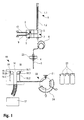
- FIG. 1 shows a schematic representation of a first embodiment of an inventive device.
- the solenoid valve 2 with an input and an output, the tees 7 and 8 and the metering device form a unit. This is formed in the present embodiment of a workpiece, for example made of plastic or metal.
- the tees 7, 8 are realized as holes in the workpiece.
- the first tee is connected via two fluid ports with fluid lines 9, 10, each with a pump, which can promote washing liquids, for example organic and inorganic washing liquids from corresponding containers (not shown).
- a third fluid port of the first tee 8 is connected to the inlet of the solenoid valve 2.
- the solenoid valve is to some extent itself the third fluid port of the first tee.
- the output of the solenoid valve 2 is connected to the second tee 7. Furthermore, the second T-piece 7 is connected to the dosing device 1 via a dilutor line, which is also designed as a bore in the workpiece.
- the metering device 1 comprises a syringe body 1.2 and a plunger 1.1, which is arranged in the syringe body 1.2 displaceable in the longitudinal direction. In the present embodiment, the plunger 1.1 is moved in the metering device 1 for mounting and ejecting each, but this is also possible by a displacement of the syringe body 1.2 at fixedly mounted plunger 1.1.
- a third fluid connection of the second T-piece 7 is connected to the hollow needle 5 via a load loop 6 and the needle adapter 4.
- a sample volume can be absorbed via the hollow needle 5 into the load loop 6.
- the load loop 6 is dimensioned in terms of its volume so that the sample volume can not get into the metering device 1.
- the metering device 1 and the load loop 6 are to some extent matched.
- the hollow needle 5 is connected via the needle adapter 4 with a needle adapter holder 23.
- the two tees 7, 8, the solenoid valve 2, the metering device 1, the load loop 6, the needle adapter 4, the hollow needle 5 and the needle adapter holder 23 are fixed relative to each other on a holder 25 (in the FIG. 2 visible), which is displaceable by means of three mutually orthogonally oriented linear guides (not shown).
- the fluid connections 9, 10 are flexible, for example made of plastic hoses. As a result, washing liquid containers can be arranged locally fixed.
- the FIG. 1 further shows a sample holder 20 for holding sample material to be examined. Air is drawn in before drawing up sample material.
- the bracket 25 in the FIG. 2
- the hollow needle 5 can be guided to the sample holder 20 in order, with the solenoid valve 2 closed, to draw up sample material by means of the metering device 1 via the hollow needle 5 into the load loop 6. Thereafter, air is sucked into the hollow needle 5 by means of the metering device 1.
- the sample material is trapped between two air bubbles, thus preventing the sample material from contaminating with washing liquid.
- the air bubbles can be dispensed with the air bubbles.
- sample material is sensitive to air or if, for example, due to the viscosity or other properties of the sample material, mixing with the washing liquid can not take place to the extent that the measurement results would be affected.
- more sample material is absorbed than is finally used for analysis in the meter.
- HPLC high-pressure liquid chromatograph
- a washing liquid at the same time represents the mobile phase, with which exactly the volume of sample material to be used is absorbed by the metering device 1 for the analysis.
- the FIG. 1 further shows a washing module 15 with two immersion positions 18, 19 and a drainage channel 16, which leads into a waste tank 17.
- the two immersion positions 18, 19 are designed as vessels open at the top, which have an overflow into the outflow channel 16.
- the bracket 25 in the FIG. 2
- the hollow needle 5 can be introduced into the drainage channel 16.
- the solenoid valve 2 is open, washing liquid can now be pumped through the two tees 7, 8 via one or both fluid compartments 9, 10, so that the washing liquid flows through the load loop 6 and the hollow needle 5.
- the pumps are designed so that they can continuously convey washing liquid.
- the washing liquid then flows into the corresponding immersion position 18, 19 and overfills it, wherein the washing liquid passes through the overflow through the drainage channel 16 into the waste tank 17.
- the hollow needle 5 can also be introduced into the drainage channel 16 to eject by means of the pump residues of the sample material, which is located in the hollow needle 5 or in the load loop 6, directly into the waste tank 17.
- the outside of the hollow needle 5 is not unnecessarily contaminated with sample material.
- a washing station is designed such that two rod-shaped inserts (immersion positions 18, 19) with different bore diameters 18.1, 18.2 and 19.1, 19.2 are arranged. These each have a narrow inlet bore 18.1, 19.1 at the top, through which the needle just comes through and have a slightly larger bore 18.2, 19.2 in the lower part.
- Lateral Auslassibohrüngen 18.3, 19.3 at the height of the transition of the two bore sections 18.1, 18.2 and 19.1, 19.2 then serve the fact that the washing stream can flow out at this point laterally and drain into the drainage channel.
- the dipping positions 18, 19 may have a shape of a straight prism, in particular a tubular shape.
- the FIG. 1 further shows an injection valve 22, which includes an injection port 21 and a loop 24.
- the injection port 21 of the injection valve 22 comprises a valve and can thus be switched between loop 24 and waste tank. In a first position, liquid injected into the injection port 21 is taken directly into the waste tank 17 directed. In a second position, injected liquid into the injection port 21 is directed into the loop 24.
- the hollow needle 5 which together with the load loop 6, the sample material, enclosed by two air bubbles, and is washed outside, are introduced into the injection port 21 of the injection valve 22.
- a first volume is ejected directly into the waste tank.
- the first volume comprises the last recorded bubble and a portion of the sampled material.
- the injection port 21 is switched to the second position and thus connected to the loop 24.
- the metering device By means of the metering device, exactly the volume of sample material required for the analysis is pumped into the loop 24, whereby a residual amount of sample material still remains in the hollow needle 5 and possibly also in the load loop 6.
- the injection port 21 is switched back to the first position.
- the rest of the sample material and the second air bubble are ejected by the metering device 1 through the hollow needle 5 in the direction of the waste tank 17.
- the solenoid valve 2 is now opened and pumped by the pump first and / or second washing liquid through the hollow needle 5 into the injection port, wherein the injection port 21 in the first position, the washing liquid in the waste tank 17th passes.
- the sample material can be pumped out of the loop 24 to the measuring device by means of a further pump (not shown).
- the hollow needle 5 can be performed by the injection port 21 in the second dipping position 19 and flushed with the second washing liquid to wash the needle inside and outside. Subsequently, we the hollow needle 5 in turn by means of the bracket 25 in the injection port 21, wherein this is flushed with the first washing liquid.
- the injection port 21 is in the first position, so that the washing liquid enters the waste tank 17.
- the hollow needle 5 is guided by means of the holder 25 in the first dipping position 18 and flushed with the first washing liquid and washed outside. The washing liquid passes through the overflow through the drainage channel 16 into the waste tank 17. Now, the solenoid valve 2 is closed and the hollow needle 5 is transferred by means of the holder 25 in a rest position until the next cycle starts.
- FIG. 2 shows a more detailed schematic oblique view of the movable part of the inventive device, which the two fluid connections 9, 10, the solenoid valve 2, the two tees 8, 9 (not explicitly shown), the metering device 1, the load loop 6, the hollow needle 5, the needle adapter 4 and the needle adapter holder 23 shows.
- the needle adapter 4 and / or the needle adapter holder 23 are resilient. This ensures that the hollow needle 5 can be sealed tightly in the injection port 21 under the spring pressure, so that through the needle 5 ejected liquid (sample material or washing liquid) can not escape between the hollow needle 5 and the injection port 21.
- FIG. 2 a bracket 25 to which all the above parts are connected either directly or indirectly.
- the holder 25 is designed substantially as a rectangular plate with a rear holding device for one or more linear guides, with which the holder is movable.
- the holder can be moved spatially by means of a linear guide typically in the needle longitudinal direction or by means of an additional linear guide in a plane or by a total of three linear guides.
- the load loop 6, the needle 5 and the metering device 1 are formed replaceable.
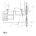
- FIG. 3 shows a section through the movable part of the inventive device substantially according to the FIG. 2 ,
- the tees 7 and 8 are each formed of a workpiece in the present embodiment.
- the tee 8 has three bores in communication, two of the bores being connected to fluid connections 9, 10 and a third bore being connected to the inlet of the solenoid valve 2.
- the same workpiece has two more, communicating bores, wherein a first bore is connected to the output of the solenoid valve 2 and the second bore communicates with the second T-piece 7 in communication.
- the second T-piece 7 is also formed from a workpiece and has three holes communicating with each other, wherein a first bore is in communication with the first tee 8, a second bore forms a connection element for the metering device 1 and a third Bore forms a connection element for the load loop 6, which in the FIG. 3 only as an approach is apparent.
- the two workpieces are screwed so that the connection between the two T-pieces 7, 8 is tight.
- the formation of the two tees 7, 8 of individual workpieces is advantageous because all fluid connections
- the diameters of the bores (lines) of the two T-pieces 7, 8 are each 1 mm.
- a bore has a length between 5 mm and 30 mm.
- the connecting line between the second T-piece 7 and the metering device is 0.41 mm and the inner diameter of the load-loop 6 is 0.5 mm.
- the length of the load-loop 6 is variable, that is, the load-loop 6 is interchangeable and adaptable to the given circumstances.
- This has a diameter in the present embodiment of 1 mm or 0.72 mm and a length (maximum stroke volume) of 19.5 mm. Overall, the dimensions are to be understood as an example only.
- an enlargement or reduction of the individual fluid connections must not be proportional to each other.
- the entire device can be dimensioned substantially larger.
- the lines / holes can diameter of several millimeters and the metering device 1 may have a stroke volume of several milliliters.
- the lengths of the holes should be kept as short as possible overall in order to achieve a small overall volume. This is important to be able to quickly switch between the two washing liquids.
- the so-called dead volume total volume of the lines from the first tee 8
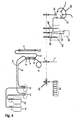
- Fig. 4 shows a schematic representation of a second embodiment of an inventive device.
- the device is based on an X.Y.Z. Unit where it is relevant to the choice of material and flushing volume, which components with the X.Y.Z. Arm are moved and which components are fixed.
- the washing lines 9 and 10 are flexible and connect the fixed components (reference numerals 11-22) with the moving components (reference numerals 1-8).
- the moving components 1-8 are located on the Z-axis.
- the valve 2 disconnects the dilutor 1 (metering device 1) from the washing lines 9 and 10 and thus from the washing pumps 11 and 12.
- the sucking and dosing of the samples takes place exclusively via the hollow needle 5 with the dilutor 1.
- the volume of the load loop 6 is so large that the sample does not reach the maximum stroke of the diluter 1 T-piece 7 can reach the output of the valve 2.
- the cleaning is typically carried out with two different solvents 13 and 14 (aqueous / organic) by means of the washing pumps 11 and 12, which via the washing lines 9 and 10 through the valve 2, through the load loop 6, through the needle adapter 4 and through the hollow needle 5 are pressed.
- the area contaminated with the sample without diluter 1, in particular without contaminating the diluter 1, can be rinsed quickly and with different solvents (cleaning agents, washing liquids) 13 and 14, in particular flushed continuously. If the needle is moved into the dipping positions 18 and 19 of the washing module 15, the outside area of the hollow needle 5 contaminated with the sample can also be cleaned. If the hollow needle is in the injection port 21 of the injection valve 22, a sample can be dosed on the one hand with the diluter 1 and, on the other hand, flushed and cleaned with the washing solvents 13 and 14 by means of the washing pumps 11 and 12 of the injection port 21 and the injection valve 22. Via the drainage channel 16, the washing solvents flow into the waste tank 17.
- solvents cleaning agents, washing liquids
- the positions with the reference numbers 1-8 are mounted directly on the Z axis.
- the volume of the washing lines 9 and 10 and the washing pumps 11 and 12 is through the valve 2 from the volume of the diluter 1, the dilutor line 3, the load loop 6 and the hollow needle 5 disconnected.
- the load loop 6 can now be formed from a rigid material such as a solid plastic or metal and, for example, as a hose, or as described above from one or more corresponding holes having workpieces. As a result, the dosing accuracy and repeatability are improved, since both are negatively influenced neither by a large dead volume nor by flexible and soft lines.
- sample dispensers In known sample dispensers, one of the most significant causes of sample carryover is the fact that sample is drawn into the syringe and that the sample volume located in the needle is also drawn into the syringe during washing. By means of several piston strokes, the sample is then washed out, but this results in only one dilution series.
- the spindle containing the syringe plunger moved may have a small pitch, which brings an advantage in the resolution of the syringe piston stroke.
- the amount of wash solvent used to clean the syringe depends on the syringe plunger strokes. Ie. the more washing solvent is to be used for cleaning, the more strokes must be performed with the syringe plunger. However, a correspondingly high number of strokes increases the syringe wear,
- the inventive device is constructed so that even existing equipment can be converted with reasonable effort.
- the design and construction prevent sample from entering the diluter 1 and, with sufficient, in principle even any amount of aqueous and / or organic washing solution, the area contaminated by the sample in the needle 5 (hollow needle 5) in the load tube (FIG. Load loop 6) and can be washed quickly and easily in the injection valve 22 and that the needle 5 is optimally positioned in the injection port 21.
- the needle 5 is connected to the union with the load tube 6 and fixed in the needle adapter (needle adapter 4),
- the needle adapter 4 springs the needle 5 minimally, so that the needle 5 can be positioned in the injection port 21 to stop.
- the volume of the Load-Tube 6 corresponds to about 1.5 times the Dilutorvolumen.
- the valve 2 (here a check valve 2) disconnects the washing lines 9 and 10 from the dilutor 1, from the load tube 6 and from the needle 5.
- the dosing accuracy of the diluter 1 is not affected by the volume and possible air bubbles in the washing lines 9 and 10.
- the first connection element Wash Inlet T-Union 8 which is positioned directly on the non-return valve 2, allows the quick change of the two wash eluents,
- the wash and waste module (washing module 15) can be positioned at the level and near the injector port 21. Due to the washing pumps 11, 12 no static pressure for washing is needed. It is possible to use standard 1 or 2 liter wash eluent bottles.
- the needle gauge has 22 / 22s or other commercial dimensions.
- An injection cycle usually includes a pre-wash macro, an injection macro and a clean macro. Furthermore, an init-macro is needed to fill the dilutor, all lines and washports.
- the diluter 1 is wetted and filled with the init macro.
- the needle 5 is to be in waste position 16. While washing pump 12 is active, is sucked with the diluter 1, the piston stroke speed must be smaller than the flow rate of the washing pump. Thereafter, the diluter 1 is ejected and the same repeated with washing pump 11. The diluter 1 is then filled with water. Wash 19 is then overfilled with Wash Eluent 14 (organic) and then Wash 18 with Wash Eluent 13 (aqueous).
- the needle is positioned in the injection port 21. Thereafter, washing pump 11 is briefly activated (about 5 seconds). Thereafter, the needle 5 is pulled out of the injection port 21 and the dilutor sucks in 1 .mu.l of air.
- the effective sample volume is enclosed in the hollow needle 5 by a selectable lead segment ("front volume”) and a selectable trailing segment (“rear volume”) before and after the sample volume is drawn up.
- the front volume prevents dilute sample from being separated from the sample volume to be injected.
- the rear volume ensures that no air or system fluid gets into the analyzer system at the end of the sample volume to be injected.
- the needle 5 moves into the sample bottle 20 and sucks in sample.
- the volumes can be changed. Also, with small amounts of sample present, the front and rear volumes, separated by small air bubbles, could be taken out of Wash 18. After the sample has been aspirated, air can be aspirated.
- the aspirated air volume can basically be determined by the user and is for example 3 ⁇ l.
- the needle now briefly moves completely into the Wash 18 position in order to wash the needle 5 on the outside. After that, the needle 5 is positioned in the injection port 21.
- the front volume eg 5 ⁇ l
- the injection volume is pressed into the loop 24 and the injection valve 21 is rotated to injection position (start signal out ). Then the dilutor 1 is completely expelled,
- the needle 5 remains in the injection port 21 and the washing pump 12 (organic) is activated (about 2-5 times the diluter volume). Thereafter, the needle 5 moves into the wash 19 position and wash pump 12 (organic) is reactivated (about 100 ⁇ l). Thereafter, the needle 5 moves to the waste position 16 and wash pump 11 is activated. After about 2 times Dilutorvolumen moves the needle 5 in the Wash 18 position. As soon as the needle 5 is in the wash position 18, the washing pump 11 is switched on again and another approx. 2 diluter volumes are pumped (end of the injection cycle).
- the dilutor piston could be withdrawn slightly, with the aspiration speed being less than the wash pump delivery rate. The ejection could then be done quickly. With this piston movement, the eluent is renewed in the dilutor. Also, during the injector port cleaning phase, the needle 5 could be retracted by about 1 mm to achieve better port cleaning.
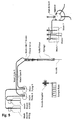
- Fig. 5 shows a third embodiment of an inventive device in which the syringe (dilutor) and the hollow needle are not separated and only at the entrance, but not at the outlet of the check valve (check valve) a connection element (T-piece) is provided.
- a syringe (syringe) with a hollow punch (hollow piston) is used instead of the standard syringe.
- the Wash-Inlet T-Union and Check-Volve will be located at the entrance of the Hollow Temple. The cleaning is then carried out from the back, ie from the container or containers with washing liquid via Wash Inlet T-Union, Check valve, syringe with hollow punch through the hollow needle.
- the invention provides a device for receiving a sample and dispensing the sample into a sample receiving input of a measuring device, which is particularly robust with respect to reproducibility, carryover.
- the inventive device is characterized by a particularly simple and compact design.
Abstract
Description
Die Erfindung betrifft eine Vorrichtung zur Aufnahme einer Probe und zur Abgabe der Probe in einen Probenaufnahmeeingang eines Messgeräts, umfassend ein erstes Anschlusselement mit drei Fluid-Anschlüssen und ein zweites Anschlusselement sowie eine Hohlnadel (5) zur Aufnahme und Abgabe der Probe, wobei eine erste Zuleitung für eine erste Waschflüssigkeit über eine erste Pumpe mit einem ersten Fluid-Anschluss des ersten Arschlusselements und eine zweite Zuleitung für eine zweite Waschflüssigkeit über eine zweite Pumpe mit einem zweiten Fluid-Anschluss des ersten Anschlusselements verbunden ist.The invention relates to a device for receiving a sample and dispensing the sample into a sample receiving inlet of a measuring device, comprising a first connection element with three fluid connections and a second connection element and a hollow needle (5) for receiving and dispensing the sample, wherein a first supply line is connected for a first washing liquid via a first pump with a first fluid port of the first Arschlusselements and a second supply line for a second washing liquid via a second pump with a second fluid port of the first connection element.
Die Aufgabe einer solchen Vorrichtung (auch als Probenaufgabevorrichtung, Autosampler oder Probenaufgabesystem bezeichnet) ist es, Proben (Samples) einer Messanordnung wie beispielsweise einem Chromatographen zuzuführen.The object of such a device (also referred to as sample application device, autosampler or sample application system) is to supply samples to a measurement device such as a chromatograph.
Aus der
Die
Die
Aus der
Durch immer empfindlicher werdende Messinstrumente (Detektoren) ergibt sich der Bedarf nach Probenaufgabesystemen welche hinsichtlich Verschleppung (Crosscontamination), Wiederholgenauigkeit (Reproduzierbarkeit), Geschwindigkeit und Langlebigkeit (Robustheit) wesentlich besser sein müssen als herkömmliche Systeme.With increasingly sensitive measuring instruments (detectors) there is a need for sample introduction systems which have to be considerably better in terms of carryover (cross contamination), repeatability (reproducibility), speed and durability (robustness) than conventional systems.
Die Vorrichtungen gemäss dem Stand der Technik haben den Nachteil, dass die Injektionsnadel nicht effizient gereinigt werden kann, Weiter kann eine Verschleppung des Probenmaterials nur teilweise verhindert werden. Schliesslich ist das aufzunehmende Probenvolumen nicht in optimaler Weise reproduzierbar.The devices according to the prior art have the disadvantage that the injection needle can not be cleaned efficiently, further, a carryover of the sample material can only be partially prevented. Finally, the sample volume to be recorded is not optimally reproducible.
Aufgabe der Erfindung ist es daher, eine dem eingangs genannten technischen Gebiet zugehörende Vorrichtung bzw. ein entsprechendes Reinigungsverfahren zu schaffen, welche eine möglichst geringe Verschleppung bei gleichzeitig hoher Genauigkeit, Geschwindigkeit und Langlebigkeit ermöglicht.The object of the invention is therefore to provide a device belonging to the aforementioned technical field or a corresponding cleaning method, which allows the lowest possible carryover while maintaining high accuracy, speed and longevity.
Die Lösung der Aufgabe ist durch die Merkmale des Anspruchs 1 definiert. Erfindungsgemäss umfasst die Vorrichtung zur Aufnahme einer Probe und zur Abgabe der Probe in einen Probenaufnahmeeingang eines Messgeräts eine verfahrbare Halterung mit einer Hohlnadel zur Aufnahme und zur Abgabe der Probe sowie eine Dosiervorrichtung, die über ein zweites Anschlusselement mit der Hohlnadel verbunden ist. Die Hohlnadel sowie die Dosiervorrichtung sind gegeneinander räumlich fixiert angeordnet, wobei zwischen dem zweiten Anschlusselement und der Hohlnadel eine starre Fluid-Verbindung angeordnet ist. Die Dosiervorrichtung ist hierbei zur Aufnahme und Abgabe der Probe durch die Hohlnadel hindurch mit dieser verbunden.The solution of the problem is defined by the features of
Durch die gegenseitige räumliche Fixierung, insbesondere der Hohlnadel und der Dosiervorrichtung, wird erreicht, dass keine flexible Fluidleitung zwischen der Hohlnadel und der Dosiervorrichtung vorgesehen sein muss. Dies hätte nämlich den Nachteil, dass bei einem Verfahren der Hohlnadel zwischen den Probenbehältern und dem Injektionsventil die flexible Fluidleitung gebogen würde, womit unkontrollierbare Volumenänderungen auftreten können. Dies wiederum hätte einen negativen Einfluss auf eine Reproduzierbarkeit von Probenabgaben in Probenaufnahmeeingängen in Messgeräten. Gemäss dieser Ausführung sind also lediglich die Zuleitungen für die Waschflüssigkeiten flexibel ausgebildet.The mutual spatial fixation, in particular the hollow needle and the metering device, ensures that no flexible fluid line between the hollow needle and the metering device must be provided. This would have the disadvantage that in a method of the hollow needle between the sample containers and the injection valve, the flexible fluid line would be bent, which uncontrollable changes in volume can occur. This in turn would have a negative impact on reproducibility of sample deliveries in sample receiving inputs in measuring instruments. According to this embodiment, therefore, only the supply lines for the washing liquids are flexible.
Es könnten auch das Injektionsventil und die Probenbehälter verfahrbar ausgebildet sein. Damit würde aber das Problem nur scheinbar gelöst, da Verbindungselemente zwischen dem Injektionsventil und dem Messgerät flexibel ausgebildet sein müssten. Zudem wäre der konstruktive Aufwand erheblich grösser.It could also be designed to be movable the injection valve and the sample container. But this would only seemingly solve the problem since connecting elements between the injection valve and the measuring device would have to be flexible. In addition, the design effort would be considerably larger.
Die starre Fluid-Verbindung ist vorzugsweise als sogenannter Load-Loop ausgebildet, in welchen das Probenmaterial aufgesogen wird. Dies hat den Vorteil, dass das Probenmaterial nicht in die Dosiervorrichtung gelangt.The rigid fluid connection is preferably designed as a so-called load loop, in which the sample material is absorbed. This has the advantage that the sample material does not get into the metering device.
Der Load-Loop ist weiter bevorzugt auswechselbar ausgebildet, insbesondere wenn die Dosiervorrichtung auch auswechselbar ausgebildet ist. So kann das Volumen der dritten Fluid-Verbindung respektive des Load-Loops dem maximalen Volumen der Dosiervorrichtung angepasst werden. Je grösser die Dosiervorrichtung dimensioniert ist, d. h. Je grösser das maximale Volumen der Dosiervorrichtung ist, desto grösser ist die dritte Fluid-Verbindung respektive der Load-Loop auszubilden, wobei mit dem maximalen Volumen der Dosiervorrichtung das maximal aufnehmbare Volumen zum Beispiel durch dessen Spritzenkörper zu verstehen ist.The load loop is further preferably made exchangeable, in particular if the metering device is also designed to be replaceable. Thus, the volume of the third fluid connection or the load-loop can be adapted to the maximum volume of the metering device. The larger the metering device is dimensioned, d. H. The greater the maximum volume of the metering device, the greater the third fluid connection or the load loop form, with the maximum volume of the metering device is to be understood as the maximum recordable volume, for example, by the syringe body.
Vorzugsweise ist die starre Fluid-Verbindung zwischen dem zweiten Anschlusselement und der Nohlnadel aus einem starren Material, insbesondere aus einem Metall oder einem festen Kunststoff, ausgebildet. Dadurch wird eine besonders hohe Genauigkeit und Reproduzierbarkeit der zu dosierenden Volumina erreicht, da sich die Fluid-Verbindungen nicht verformen können.The rigid fluid connection between the second connection element and the hollow needle is preferably formed from a rigid material, in particular from a metal or a solid plastic. As a result, a particularly high accuracy and reproducibility of the volumes to be dispensed is achieved since the fluid connections can not deform.
Um eine besonders kompakte, stabile und konstruktiv einfache Ausführung zu erhalten, kann die starre Fluid-Verbindung als Bohrung in einem massiven Element aus Metall oder Kunststoff realisiert werden. Dies hat weiter den Vorteil, dass insbesondere die Verbindungsstellen auch bei hoher Druckbeanspruchung dicht bleiben. Schliesslich ist diese Ausführung auch aus ästhetischer Sicht zu bevorzugen.In order to obtain a particularly compact, stable and structurally simple design, the rigid fluid connection can be realized as a bore in a solid element made of metal or plastic. This has the further advantage that in particular the joints remain tight even at high pressure stress. Finally, this version is also preferable from an aesthetic point of view.
Bevorzugt ist zwischen dem zweite Anschlusselement und der Dosiervorrichtung eine Dilutorleitung angeordnet, welche als Bohrung in einem Werkstück aus Kunststoff oder Metal ausgebildet ist.Preferably, a Dilutorleitung is arranged between the second connection element and the metering device, which is formed as a bore in a workpiece made of plastic or metal.
Bevorzugt umfasst die Vorrichtung zusätzlich ein erstes Anschlusselement mit drei Fluid-Anschlüssen, wobei ein Fluid-Anschluss des zweiten Anschlusselements mit dem dritten Fluid-Anschluss des ersten Anschlusselements verbunden ist. Eine erste Zuleitung für eine erste Waschflüssigkeit ist über eine erste Pumpe mit dem ersten Fluid-Anschluss des ersten Anschlusselements und eine zweite Zuleitung für eine zweite Waschflüssigkeit über eine zweite Pumpe mit dem zweiten Fluid-Anschluss des ersten Anschlusselements verbunden. Zwischen dem dritten Fluid-Anschiuss des ersten Anschlusselements und dem zweiten Element ist ein Ventil angeordnet.The device preferably additionally comprises a first connection element with three fluid connections, wherein a fluid connection of the second connection element is connected to the third fluid connection of the first connection element. A first supply line for a first washing liquid is connected via a first pump to the first fluid connection of the first connection element and a second supply line for a second washing liquid via a second pump to the second fluid connection of the first connection element. Between the third fluid connection of the first connection element and the second element, a valve is arranged.
Dieser Aufbau ermöglicht nicht nur eine schnelle und einfache Spülung der Hohlnadel und der mit der Hohlnadel bzw. der Probe in Berührung kommenden Teile der Vorrichtung wie beispielsweise das Injektionsventil, durch welches hindurch die Probe an das Messgerät abgegeben wird, sondern auch eine Spülung der Hohlnadel, solange diese noch im Injektionsport des Injektionsventils steht, d. h. ohne die Hohlnadel zuerst vom Injektionsport entfernen zu müssen.This structure not only allows a quick and easy flushing of the hollow needle and the parts of the device that come into contact with the hollow needle or the sample, such as the injection valve, through which the sample is delivered to the measuring device, but also a flushing of the hollow needle, while it is still in the injection port of the injection valve, d. H. without first having to remove the hollow needle from the injection port.
Zudem ermöglicht die erfindungsgemässe Anordnung der einzelnen Teile der Vorrichtung das im Wesentlichen ununterbrochene, respektive kontinuierliche Reinigen der Vorrichtung, da mit der ersten und/oder der zweiten Waschpumpe solange Waschflüssigkeit durch die Hohlnadel hindurch gepumpt werden kann, bis die Nadel gereinigt oder schliesslich ein Vorrat an Waschflüssigkeit erschöpft ist. Natürlich kann in letzterem Fall, je nach Ausbildung der Vorrichtung während des Betriebs auch ein Vorrat an Waschflüssigkeit nachgefüllt werden.In addition, the inventive arrangement of the individual parts of the device allows the substantially uninterrupted, respectively continuous cleaning of the device, since with the first and / or the second washing pump as long as washing liquid can be pumped through the hollow needle until the needle cleaned or finally a supply Washing liquid is exhausted. Of course, in the latter case, depending on the design of the device during operation, a supply of washing liquid can be refilled.
Durch Aktivierung der Pumpen wird es möglich, die Vorrichtung bzw. Teile davon sehr schnell und einfach und mit beliebigen Mengen zweier verschiedener Waschflüssigkeiten (Lösungsmitteln), beispielsweise einer wässrigen und einer organischen Waschflüssigkeit, zu reinigen, ohne dass hierfür ein Ventil umgeschaltet werden muss. Zudem wird das Durchspülen der Hohlnadel und des Injektionsventils ermöglicht, während die Hohlnadel im Injektionsport steht ohne dass die Hohlnadel bewegt werden muss.By activating the pumps, it is possible to clean the device or parts thereof very quickly and easily and with any desired amounts of two different washing liquids (solvents), for example an aqueous and an organic washing liquid, without having to switch over a valve for this purpose. In addition, the flushing of the hollow needle and the injection valve is made possible while the hollow needle is in the injection port without the hollow needle has to be moved.
Durch die Ausbildung eines Ventils zwischen dem dritten Fluid-Anschluss des ersten Anschlusselements und dem zweiten Anschlusselement kann ein Rückflusses eines Fluids (Probe, Waschflüssigkeit) in Richtung einer Zuleitung einer Waschflüssigkeit verhindert werden. Insbesondere kann dadurch die Vorrichtung besonders einfach gehalten werden, da abgesehen vom Probeneingang zum Messgerät kein weiteres Ventil zwingend benötigt wird. So können mit nur einem Ventil die mehreren Waschflüssigkeiten angesteuert werden, in dem die entsprechende Pumpe aktiviert und das Ventil geöffnet wird. Um den Rückfluss aktiv verhindern zu können, kann dazu ein gesteuertes Ventil eingesetzt werden.By forming a valve between the third fluid connection of the first connection element and the second connection element, a backflow of a fluid (sample, washing liquid) in the direction of a supply line of a washing liquid can be prevented. In particular, this means that the device can be kept particularly simple, since apart from the sample input to the measuring device, no further valve is absolutely necessary. Thus, with just one valve, the several washing liquids can be controlled, in which the corresponding pump is activated and the valve is opened. To be able to actively prevent backflow, a controlled valve can be used for this purpose.
Die Pumpen sind vorzugsweise so ausgebildet, dass sie Waschflüssigkeiten kontinuierlich fördern können. Die Pumpen können als Schlauchquetschpurnpen, Membranpumpen, Rotationskolbenpumpen, Drehkolbenpumpen, Drehschieberpumpen, Kreiskolbenpumpen, Zahnradpumpen oder als Kolbenpumpen, insbesondere als Axialkolbenpumpen oder Hubkolbenpumpen ausgebildet sein.The pumps are preferably designed so that they can continuously convey washing liquids. The pumps can be used as hose crimping pumps, diaphragm pumps, Rotary piston pumps, rotary lobe pumps, rotary vane pumps, rotary piston pumps, gear pumps or be designed as piston pumps, in particular as axial piston or reciprocating pumps.
Die Hohlnadel kann dazu als zylindrisches Hohlelement ausgebildet sein, insbesondere als Kanüle, wobei die Kanüle eine Austrittsöffnung umfasst, welche gerade und/oder abgeschrägt sein kann. Damit kann die Hohlnadel einfach zum Beispiel durch eine Membrane gestossen werden. Weiter können auch Einwegaufsätze verwendet werden.The hollow needle may be designed as a cylindrical hollow element, in particular as a cannula, wherein the cannula comprises an outlet opening, which may be straight and / or bevelled. Thus, the hollow needle can be easily pushed, for example, through a membrane. Furthermore, disposable attachments can also be used.
Das Ventil ist vorzugsweise als Magnetventil, insbesondere als Magnetventil mit einem Nennvolumen kleiner als 0.1 ml ausgebildet. Ein Magnetventil ist ein Ventil, das von einem Elektromagneten betätigt wird. Die Verwendung eines Magnetventils hat gleich mehrere Vorteile:
- 1. Magnetventile sind steuerbar und können damit unabhängig von einem Leitungsdruck geschalten werden.
- 2. Magnetventile weisen kleine Schaltzeiten auf, insbesondere können Schaltzeiten im Bereich von Millisekunden erreicht werden.
- 3. Schaltfrequenzen im Kiloherzbereich sind möglich.
- 4. Magnetventile sind in kompakter Bauweise verfügbar.
- 5. Magnetventile sind wartungsarm.
- 1. Solenoid valves are controllable and can thus be switched independently of a line pressure.
- 2. Solenoid valves have small switching times, in particular switching times in the range of milliseconds can be achieved.
- 3. Switching frequencies in the kilohertz range are possible.
- 4. Solenoid valves are available in a compact design.
- 5. Solenoid valves are low maintenance.
Als Beispiel für eine Ausführung eines Magnetventils sei hier auf die Flipper-Magnetventile der Firma Bürkert verwiesen, welche sich durch besonders kleine Abmessungen (4.5 mm Breite und 38.5 mm Tiefe), kleines internes Volumen (0.03 ml) und durch eine Schaltfrequenz von bis zu 80Hz auszeichnet. Dem Fachmann sind aber eine Vielzahl von ähnlichen Magnetventifen bekannt, welche genauso eingesetzt werden können. Insbesondere können auch grössere oder kleinere Magnetventile verwendet werden, falls der Raum nicht beschränkt ist oder falls eine kostengünstigere Ausführung erwünscht ist. Weiter kann das interne Volumen je nach Anwendung auch anders gewählt werden, wobei Jedoch ein kleineres internes Volumen grundsätzlich zu bevorzugen ist. Die Schaltfrequenz kann auch kleiner als 80Hz sein, ohne nennenswerte Verluste in der Genauigkeit hinnehmen zu müssen. Schaltfrequenzen um 80Hz oder höher sind aber natürlich zu bevorzugen.As an example of a version of a solenoid valve, reference is made to the Flipper solenoid valves from Bürkert, which are characterized by particularly small dimensions (4.5 mm width and 38.5 mm depth), small internal volume (0.03 ml) and a switching frequency of up to 80Hz distinguished. The skilled person but a variety of similar solenoid valves are known, which can be used as well. In particular, larger or smaller solenoid valves can be used, if the space is not limited or if a cheaper version is desired. Furthermore, the internal volume can also be chosen differently depending on the application, although a smaller internal volume is to be preferred in principle. The switching frequency can also be less than 80Hz without accepting significant losses in accuracy to have to. Switching frequencies around 80Hz or higher are of course preferable.
Weiter kann bei der Vorrichtung auch ein anderes Ventil zwischen dem dritten Fluid-Anschluss des ersten Anschlusselements und dem zweiten Anschlusselement angeordnet sein. Zum Beispiel könnte ein Rückschlagventil zur Verhinderung eines Rückflusses eines Fluids (Probe, Waschflüssigkeit) in Richtung einer Zuleitung, insbesondere als federunterstütztes Kugel- oder Membran(rückschlag)ventil (spring-loaded check valve) ausgebildet sein. Der Druck der Feder des Ventils ist typischerweise kleiner als 1 bar, vorzugsweise etwa 0.3 bar. Dieser Druck muss von der Waschpumpe überwunden werden, um die Waschflüssigkeit durch das Rückschlagventil hindurch zu pumpen. Der Druck der Feder darf allerdings auch nicht zu gering sein, da sich das Ventil durch einen leichten, ausgangsseitigen Unterdruck, wie dies durch einen Kolbenhub des Dilutors (der nachfolgend auch als Spritze bezeichnet wird) entstehen kann, nicht öffnen darf. Diese Probleme können durch den Einsatz eines gesteuerten Ventils, insbesondere eines Magnetventils behoben werden.Furthermore, another valve may be arranged between the third fluid port of the first connection element and the second connection element in the device. For example, a check valve for preventing a backflow of a fluid (sample, washing liquid) in the direction of a supply line, in particular as a spring-assisted ball or membrane (check) valve (spring-loaded check valve) may be formed. The pressure of the spring of the valve is typically less than 1 bar, preferably about 0.3 bar. This pressure must be overcome by the wash pump to pump the wash fluid through the check valve. However, the pressure of the spring may not be too low, since the valve must not open due to a slight, negative pressure on the output side, as can be caused by a piston stroke of the Dilutor (which is also referred to as a syringe below). These problems can be solved by using a controlled valve, in particular a solenoid valve.
Dieses Magnetventil ersetzt das beim Stand der Technik gemäss
Bevorzugt umfasst das zweite Anschlusselement drei Fluidanschlüsse, wobei ein erster Fluidanschluss des zweiten Anschlusselements mit dem Ventil, ein zweiter Fluidanschluss des zweiten Anschlusselements mit der Dosiervorrichtung und ein dritter Fluidanschluss des zweiten Anschlusselements mit der Hohlnadel verbunden ist. In einem ersten Zustand ist das Ventil geschlossen, womit bei einer Aktivierung der Dosiervorrichtung zum Beispiel eine Flüssigkeit über das zweite Anschlusselement durch die Hohlnadel pumpbar ist, ohne dass die Flüssigkeit mit einer Waschflüssigkeit in Kontakt kommt. In einem zweiten Zustand ist das Ventil geöffnet. In diesem Zustand wird die Dosiervorrichtung typischerweise nicht aktiviert, da durch Sogwirkung (Bernoulliprinzip) der betätigten Dosiervorrichtung über das zweite Anschlusselement Waschflüssigkeit angesaugt werden könnte, insbesondere, wenn die Pumpen keine Rücklaufsicherung aufweisen. Im zweiten Zustand, das heisst bei offenem Ventil, wird typischerweise eine Reinigung durchgeführt. Dabei wird mittels der ersten und/oder der zweiten Pumpe Waschflüssigkeit durch das erste Anschlusselement über das Ventil und das zweite Anschlusselement durch die Hohlnadel hindurch gepumpt. Durch diese Anordnung kann die Dosiervorrichtung bei einem Reinigungsvorgang ausgekoppelt werden. Dadurch kann mit konstruktiv einfachen Mitteln verhindert werden, dass Waschflüssigkeit in die Dosiervorrichtung gelangt.The second connection element preferably comprises three fluid connections, wherein a first fluid connection of the second connection element to the valve, a second fluid connection of the second connection element to the dosing device and a third fluid connection of the second connection element to the hollow needle. In a first state, the valve is closed, whereby, for example, when the dosing device is activated, a liquid can be pumped through the hollow needle via the second connecting element without the liquid coming into contact with a washing liquid. In a second state, the valve is open. In this state, the metering device is typically not activated, since by suction (Bernoulliprinzip) of the actuated metering device could be sucked via the second connection element washing liquid, in particular, if the pumps have no return protection. In the second state, ie with the valve open, cleaning is typically carried out. It will By means of the first and / or the second pump, washing liquid is pumped through the first connecting element via the valve and the second connecting element through the hollow needle. By this arrangement, the metering device can be coupled in a cleaning process. This can be prevented with structurally simple means that washing liquid enters the metering device.
Weiter kann das zweite Anschlusselement auch durch die Dosiervorrichtung selbst oder einen Teil davon realisiert sein. Dazu würde der Ausgang des Ventils direkt mit der Dosiervorrichtung verbunden, das heisst, zwischen dem Ventil und der Dosiervorrichtung wäre eine Fluid-Verbindung vorgesehen. Die Hohlnadel würde dann separat mit der Dosiervorrichtung über eine weitere Fluid-Verbindung verbunden werden. Dies hätte aber den Nachteil, dass die Dosiervorrichtung zwangsläufig mit Waschflüssigkeit kontaminiert werden würde.Furthermore, the second connection element can also be realized by the metering device itself or a part thereof. For this purpose, the output of the valve would be connected directly to the metering device, that is, between the valve and the metering device, a fluid connection would be provided. The hollow needle would then be connected separately to the dosing device via a further fluid connection. However, this would have the disadvantage that the metering device would inevitably be contaminated with washing liquid.
Vorzugsweise umfasst die Dosiervorrichtung einen Spritzenkörper und einen Stössel und ist insbesondere motorisch betätigbar. Dazu umfasst die Dosiervorrichtung eine Linearführung. Der Stössel kann dazu zum Beispiel eine Zahnstange in dessen Längsrichtung umfassen, welche mit einem Zahnrad eines Motors, insbesondere eines Schrittmotors, zusammenwirkt. Damit kann der Stössel mittels einer Betätigung des Motors in dessen Längsrichtung verschoben und damit können besonders präzise Hübe ausgeführt werden, wodurch ein zu dosierendes Volumen genau eingestellt werden kann. Weiter wird durch den motorischen Betrieb der Dosiervorrichtung auch eine Steuerung mittels eines Computers ermöglicht, womit auch komplexere Abläufe der Vorrichtung gesteuert und insbesondere automatisiert werden können. Statt des Stössels kann auch der Spritzenkörper mittels einer Linearführung bewegt werden. Die Spritze kann grundsätzlich beliebig orientiert sein. Bevorzugt ist sie jedoch vertikal, mit einer Austrittsöffnung nach unten angeordnet.Preferably, the metering device comprises a syringe body and a plunger and is in particular motor-actuated. For this purpose, the metering device comprises a linear guide. For this purpose, the plunger may, for example, comprise a toothed rack in its longitudinal direction, which cooperates with a toothed wheel of a motor, in particular a stepping motor. Thus, the plunger can be moved by means of an actuation of the motor in the longitudinal direction and thus very precise strokes can be performed, whereby a volume to be metered can be accurately adjusted. Further, the motor operation of the metering device also allows control by means of a computer, whereby more complex processes of the device can be controlled and, in particular, automated. Instead of the plunger and the syringe body can be moved by means of a linear guide. The syringe can basically be oriented arbitrarily. However, it is preferably arranged vertically, with an outlet opening facing downwards.
Statt einer motorischen Betätigung ist auch eine pneumatische oder eine manuelle Betätigung der Dosiervorrichtung denkbar. Ein pneumatischer Antrieb ist insbesondere dann denkbar, wenn das zu dosierende Volumen nicht regelmässig geändert wird. In diesem Fall kann nämlich die Dosiervorrichtung bezüglich der Pneumatik einen Anschlag aufweisen, welche eine Bewegung der Pneumatik begrenzt und damit das zu dosierende Volumen definiert. Der Anschlag kann dazu verstellbar ausgebildet sein, so dass verschiedene Volumina dosierbar sind.Instead of a motor actuation also a pneumatic or a manual actuation of the metering device is conceivable. A pneumatic drive is particularly conceivable when the volume to be dispensed is not changed regularly. In this case, namely, the metering device with respect to the pneumatics have a stop which limits a movement of the pneumatic and thus the metered Volume defined. The stop can be designed to be adjustable, so that different volumes can be metered.
Bevorzugt ist die Dosiervorrichtung auswechselbar ausgebildet, insbesondere durch Dosiervorrichtungen verschiedener Volumina ersetzbar. Damit wird eine besonders flexibel einsetzbare Vorrichtung erreicht. Typischerweise sind die zu analysierenden Volumina nicht immer gleich gross. Je nach Konzentration oder Art des zu untersuchenden Stoffes wird daher ein unterschiedliches Volumen an Probenmaterial untersucht. Durch die auswechselbar ausgestaltete Dosiervorrichtung können zum Beispiel verschiedene Spritzen, umfassend den Spritzenkörper und den Stössel, mit verschiedenen maximalen Volumina zur Verfügung stehen, so dass die Vorrichtung den jeweiligen Messungen und damit zu dosierenden Volumina angepasst werden kann. Insbesondere kann damit eine relative Genauigkeit des zu dosierenden Volumens auch bei unterschiedlichen Volumina aufrecht erhalten werden.Preferably, the metering device is designed replaceable, in particular replaced by metering devices of different volumes. For a particularly flexible device is achieved. Typically, the volumes to be analyzed are not always the same size. Depending on the concentration or type of substance to be examined, therefore, a different volume of sample material is examined. By means of the exchangeably configured metering device, for example, different syringes, comprising the syringe body and the plunger, can be available with different maximum volumes, so that the device can be adapted to the respective measurements and thus to volumes to be metered. In particular, a relative accuracy of the volume to be dispensed can thus be maintained even with different volumes.
Alternativ, insbesondere für den Einsatz bei Routineanalysen, kann auch auf ersetzbare Dosiervorrichtungen verzichtet werden und unter Umständen dadurch die Vorrichtung kostengünstiger hergestellt werden. Dabei müssten aber möglicherweise der Verlust der obig erwähnten Vorteile, insbesondere der Verlust an Flexibilität in der Anwendung, in Kauf genommen werden,Alternatively, in particular for use in routine analyzes, replaceable dosing devices can also be dispensed with and, under certain circumstances, the device can be manufactured more cost-effectively. However, the loss of the advantages mentioned above, in particular the loss of flexibility in the application, might have to be accepted,
Vorzugsweise ist die Halterung in drel verschiedenen Raumrichtungen verfahrbar. Dies ist insbesondere dann von Vorteil, wenn die Probenbehälter in mehreren Reihen angeordnet sind. Die Verfahrbarkeit der Halterung kann mit drei Linearführungen erreicht werden, welche zum Beispiel mit Schrittmotoren angetrieben sind. Der Antrieb kann mittels einer Kombination von Zahnstangen und Antriebsritzel oder mittels einer seilzugähnlichen Vorrichtung erfolgen. Anderseits ist auch eine Montage an einem gelenkigen Roboterarm denkbar.Preferably, the holder is movable in different spatial directions. This is particularly advantageous when the sample containers are arranged in several rows. The mobility of the holder can be achieved with three linear guides, which are driven for example with stepper motors. The drive can be done by means of a combination of racks and drive pinion or by means of a cable-like device. On the other hand, an assembly on a hinged robot arm is conceivable.
Falls die Probenbehälter in nur einer Reihe angeordnet sind, d. h., wenn typischerweise wenige Probenbehälter verwendet werden, kann eine Verfahrbarkeit in zwei Raumrichtungen ausreichen, wobei die beiden Raumrichtungen in einer vertikalen Ebene orientiert sind und die Probenbehälter horizontal in derselben Ebene angeordnet sind.If the sample containers are arranged in only one row, ie, if typically only a few sample containers are used, a mobility in two spatial directions can be sufficient, the two spatial directions being oriented in a vertical plane and the sample containers being arranged horizontally in the same plane.
Die beiden Anschlusselemente sind bevorzugt auf der verfahrbaren Halterung befestigt. Dadurch, dass die beiden Anschlusselemente auf der verfahrbaren Halterung befestigt sind, wird erreicht, dass auch sie bei einer Bewegung der Halterung gemeinsam mit der Hohlnadel, der Dosiervorrichtung und dem Ventil bewegt werden. Weiter wird damit zwischen den beiden Anschlusselementen ein Volumen gering gehalten, womit schneller zwischen den zwei Waschflüssigkeiten gewechselt werden kann, ohne dass eine grössere Menge der vorherigen Waschflüssigkeit durchgespült werden muss.The two connection elements are preferably mounted on the movable holder. The fact that the two connection elements are mounted on the movable support, it is achieved that they are moved in a movement of the holder together with the hollow needle, the metering device and the valve. Furthermore, a volume is thus kept small between the two connecting elements, which makes it possible to exchange more rapidly between the two washing liquids without having to flush through a larger quantity of the previous washing liquid.
Entsprechend müssen die Hohlnadel, das Ventil, die Anschlusselemente und die Dosiervorrichtung nicht gegeneinander bewegt werden, sodass eine verbesserte Dosiergenauigkeit und Dosierwiederholbarkeit erreicht werden kann.Accordingly, the hollow needle, the valve, the connection elements and the metering device need not be moved against each other, so that an improved dosing accuracy and Dosierrepordholbarkeit can be achieved.
D. h. die einzige Verbindung zwischen den mit der Halterung beweglichen Komponenten und den nicht beweglichen Komponenten der Vorrichtung sind die Zuleitungen für die Waschflüssigkeiten. Entsprechend sind diese flexibel ausgebildet.Ie. the only connection between the components movable with the support and the non-moving components of the device are the supply lines for the washing liquids. Accordingly, these are flexible.
Das erste Anschlusselement kann auch fix angeordnet sein, womit nur eine flexible Leitung zum Ventil geführt werden müsste. Dies hätte aber den Nachteil, dass das Volumen zwischen den beiden Anschlusselementen grösser wäre und dadurch beim Wechseln zwischen den Waschflüssigkeiten eine grössere Zeitspanne vergeht, bis die andere Waschflüssigkeit zu der Hohlnadel gelangt. Des Weiteren kann sich dadurch eine Vermischung der beiden Waschflüssigkeiten über ein grösseres Volumen ergeben.The first connection element can also be arranged fixed, with which only one flexible line would have to be led to the valve. However, this would have the disadvantage that the volume between the two connecting elements would be greater and thus a longer period of time passes when changing between the washing liquids until the other washing liquid reaches the hollow needle. Furthermore, this can result in a mixing of the two washing liquids over a larger volume.
Der Load-Loop und die Hohlnadel sind vorzugsweise einstückig ausgebildet. Bei unterschiedlichen Probenvolumen ist unter Umständen auch der Durchmesser der Hohlnadel dem Probenvolumen anzupassen. Falls der Load-Loop einem neuen Probenvolumen angepasst werden soll, muss also möglicherweise sowieso die Hohlnadel entsprechend ersetzt werden, Dies ist insbesondere dann der Fall, wenn sich die Probenvolumen stark unterscheiden, wenn zum Beispiel von einem Mikroliterbereich zu einem Mililiterbereich gewechselt wird. Durch eine einstückige Ausbildung des Load-Loops zusammen mit der Hohlnadel wird so eine vereinfachte Anpassung erreicht.The load loop and the hollow needle are preferably formed in one piece. With different sample volumes, the diameter of the hollow needle may also be adapted to the sample volume. If the load loop is to be adapted to a new sample volume, the hollow needle may possibly have to be replaced anyway. This is the case, in particular, when the sample volumes differ greatly, for example when changing from a microliter range to a militer range. By a one-piece design of the load-loops together with the hollow needle as a simplified adaptation is achieved.
Die Hohlnadel und der Load-Loop können auch getrennt vorliegen, womit eine flexiblere Anpassung an die gegebenen Umstände ermöglicht wird.The hollow needle and the load loop can also be separated, thus allowing a more flexible adaptation to the given circumstances.
Die Probe ist bevorzugt flüssig. Feste Proben werden bevorzugt in einem geeigneten Lösemittel gelöst und wiederum als flüssige Proben eingesetzt.The sample is preferably liquid. Solid samples are preferably dissolved in a suitable solvent and used again as liquid samples.
Alternativ kann die Probe auch gasförmig sein, womit aber den Dichtungen und den Übergängen der Fluid-Verbindungen besondere Beachtung bezüglich Dichtigkeit geschenkt werden muss.Alternatively, the sample may also be gaseous, whereby, however, particular attention must be paid to the seals and the junctions of the fluid connections with regard to tightness.
Bevorzugt umfasst das Messgerät einen Chromatografen, insbesondere einen Flüssigchromatografen.The measuring device preferably comprises a chromatograph, in particular a liquid chromatograph.
Die Vorrichtung kann auch für andere, dem entsprechenden Fachmann hinreichend bekannte Messmethoden eingesetzt werden, bei welchen ein bestimmtes Fluid-Volumen vorgängig abgemessen werden muss. Insbesondere kann mit der Vorrichtung auch eine Probenvorbereitung vorgenommen werden. Zum Beispiel in der Mikrobilologie, in der Genetik oder ähnlichen Gebieten, wo kleinste Volumina mit hoher Genauigkeit abgemessen werden müssen, kann die Vorrichtung erfolgreich eingesetzt werden. So könnten zum Beispiel auch Zellen geimpft oder kleinste Mengen von insbesondere flüssigen Stoffen gemischt werden.The device can also be used for other measuring methods that are well known to the relevant person skilled in the art, in which case a specific fluid volume must be measured in advance. In particular, the device can also be used for sample preparation. For example, in microbilology, genetics or similar fields where smallest volumes must be measured with high accuracy, the device can be used successfully. For example, it would also be possible to vaccinate cells or to mix the smallest amounts of, in particular, liquid substances.
Vorzugsweise umfasst die Vorrichtung zur Reinigung der Hohlnadel ein Waschmodul mit einem Abfalltank und mindestens eine Tauchposition. Für einen Waschvorgang kann so die Hohlnadel über den Abfalltank geführt werden und bei offenem Ventil die erste und/oder die zweite Waschflüssigkeit mittels der entsprechenden Pumpe(n) durch die Hohlnadel hindurch in den Abfalltank gepumpt werden. Damit kann die Hohlnadel kontinuierlich gereinigt werden, ohne einer Verdünnungsreihe zu unterliegen, welche bei einem mehrmaligen Aufziehen und Ausstossen der Waschflüssigkeit durch die Dosiervorrichtung gemäss dem Stand der Technik erfolgen würde. Die Tauchposition ist als Gefäss mit einem Überlauf ausgebildet, wobei der Überlauf in den Abfalltank geleitet werden kann. Damit kann die gesamte Waschflüssigkeit in einem einzigen Tank gesammelt werden. Die Hohlnadel wird in die Tauchposition eingeführt, anschliessend wird eine Waschflüssigkeit durch die Hohlnadel hindurchgepumpt. Dabei besteht die Möglichkeit, dass das Gefäss mit der Waschflüssigkeit soweit aufgefüllt wird, dass die Hohlnadel in derselben Waschflüssigkeit eintaucht. Anderseits kann die Tauchposition auch schon im Voraus mit Waschflüssigkeit gefüllt sein. Damit wird erreicht, dass die Hohlnadel auch von aussen gewaschen werden kann. Dazu kann auch eine Beaufschlagung der Tauchposition mit Ultraschall vorgesehen sein, um den Reinigungsprozess effizienter zu gestalten. Dem Fachmann sind dazu auch weitere Möglichkeiten bekannt, mit welchen die Reinigung optimiert werden kann.Preferably, the device for cleaning the hollow needle comprises a washing module with a waste tank and at least one dipping position. For a washing process, the hollow needle can thus be guided over the waste tank and, with the valve open, the first and / or the second washing liquid can be pumped through the hollow needle into the waste tank by means of the corresponding pump (s). Thus, the hollow needle can be continuously cleaned without being subject to a dilution series, which would be done by a plurality of mounting and ejecting the washing liquid through the metering device according to the prior art. The dipping position is designed as a vessel with an overflow, wherein the overflow can be passed into the waste tank. Thus, the entire washing liquid can be collected in a single tank. The hollow needle is introduced into the dipping position, then a washing liquid is pumped through the hollow needle. There is the possibility that the vessel is filled with the washing liquid to the extent that the hollow needle is immersed in the same washing liquid. On the other hand, the diving position can also be seen in advance Be filled with washing liquid. This ensures that the hollow needle can also be washed from the outside. For this purpose, it can also be provided with ultrasound to apply the dipping position in order to make the cleaning process more efficient. The skilled person are also known to other possibilities, with which the cleaning can be optimized.
Es können auch Wegwerf-Hohlnadeln verwendet werden, womit sich eine Reinigung erübrigt. Die Vorrichtung kann so beschaffen sein, dass in einem Wegwerf-Betrieb die Hohlnadel nach der Verwendung entsorgt und in einem Wasch-Betrieb die Hohlnadel nach einer Verwendung, insbesondere nach jeder Verwendung, gereinigt werden. Dies ist insbesondere dann von Interesse, wenn besonders hohe Anforderungen an die Reinheit der Hohlnadel gestellt werden, zum Beispiel wenn sogenannte Cross-Kontamination verhindert werden soll.Disposable hollow needles can also be used, which eliminates the need for cleaning. The device may be such that in a disposable operation, the hollow needle disposed of after use and in a washing operation, the hollow needle after use, in particular after each use, to be cleaned. This is of particular interest if particularly high demands are placed on the purity of the hollow needle, for example if so-called cross-contamination is to be prevented.
Vorzugsweise umfasst die Vorrichtung ein Injektionsventil mit einem Injektionsport, wobei die Probe mit der im Injektionsport positionierten Hohlnadel via das Injektionsventil in den Probenaufnahmeeingang des Messgeräts abgebbar ist. Dies ist insbesondere dann von Vorteil, wenn das Messgerät einen Flüssigchromatographen oder einen Hochdruckflüssigchromatographen umfasst.The device preferably comprises an injection valve with an injection port, wherein the sample with the hollow needle positioned in the injection port can be dispensed via the injection valve into the sample receiving inlet of the measuring device. This is particularly advantageous if the measuring device comprises a liquid chromatograph or a high pressure liquid chromatograph.
Weiter kann das Probenmaterial auch in ein Gefäss abgegeben werden oder einer anderweitigen Weiterverarbeitung zur Verfügung gestellt werden.Furthermore, the sample material can also be dispensed into a vessel or made available for further processing.
Vorzugsweise umfasst die Vorrichtung eine Probenhalterung zur Bereithaltung von Proben. Die Probenhalterung umfasst dazu mehrere Positionen zum Platzieren von Probenbehältern. Die Probenhalterung weist dazu typischerweise eine rechteckige Grundfläche auf, wobei die Positionen in parallelen Reihen angeordnet sind. Auch eine versetzte Anordnung der Reihen ist denkbar. Dies hat den Vorteil, dass die Probenbehälter platzsparender angeordnet werden können.Preferably, the device comprises a sample holder for holding samples. The sample holder includes several positions for placing sample containers. The sample holder typically has a rectangular base area, the positions being arranged in parallel rows. An offset arrangement of the rows is also conceivable. This has the advantage that the sample container can be arranged space-saving.
Alternativ kann auf die Probenhalterung auch verzichtet werden.Alternatively, the sample holder can also be dispensed with.
Bei einem Verfahren zur Reinigung einer Vorrichtung zur Aufnahme einer Probe und zur Abgabe der Probe in einen Probenaufnahmeeingang eines Messgeräts mit einer Hohlnadel, einer ersten Zuleitung für eine erste Waschflüssigkeit, einer zweiten Zuleitung für eine zweite Waschflüssigkeit sowie einer Dosiervorrichtung wird mit der ersten Waschpumpe die erste Waschflüssigkeit und/oder mit der - zweiten Waschpumpe die zweite Waschflüssigkeit an der Dosiervorrichtung vorbei durch die Hohlnadel hindurch gepumpt.In a method for cleaning a device for receiving a sample and delivering the sample into a sample receiving input of a measuring device with a hollow needle, a first supply line for a first washing liquid, a second supply line for a second washing liquid and a metering device, the first washing liquid and / or with the second washing pump, the second washing liquid is pumped past the metering device through the hollow needle through the first washing pump.
Aus der nachfolgenden Detailbeschreibung und der Gesamtheit der Patentansprüche ergeben sich weitere vorteilhafte Ausführungsformen und Merkmalskombinationen der Erfindung.From the following detailed description and the totality of the claims, further advantageous embodiments and feature combinations of the invention result.
Die zur Erläuterung des Ausführungsbeispiels verwendeten Zeichnungen zeigen:
- Fig. 1
- eine schematische Darstellung eines ersten Ausführungsbeispiels einer erfindungsgemässen Vorrichtung;
- Fig. 2
- eine schematische Schrägansicht des verfahrbaren Teils der erfindungsgemässen Vorrichtung;
- Fig. 3
- einen Schnitt durch den verfahrbaren Teil der erfindungsgemässen Vorrichtung;
- Fig. 4
- eine schematische Darstellung eines zweiten Ausführungsbeispiels einer erfindungsgemässen Vorrichtung und
- Fig. 5
- eine schematische Darstellung eines dritten Ausführungsbeispiels einer erfindungsgemässen Vorrichtung.
- Fig. 1
- a schematic representation of a first embodiment of an inventive device;
- Fig. 2
- a schematic oblique view of the movable part of the inventive device;
- Fig. 3
- a section through the movable part of the inventive device;
- Fig. 4
- a schematic representation of a second embodiment of an inventive device and
- Fig. 5
- a schematic representation of a third embodiment of an inventive device.
Grundsätzlich sind in den Figuren gleiche Teile mit gleichen Bezugszeichen versehen.Basically, the same parts are provided with the same reference numerals in the figures.
Das Magnetventil 2 mit einem Eingang und einem Ausgang, die T-Stücke 7 und 8 und die Dosiervorrichtung bilden dabei eine Einheit. Diese ist in der vorliegenden Ausführungsform aus einem Werkstück, zum Beispiel aus Kunststoff oder Metall, gebildet. Die T-Stücke 7, 8 sind als Bohrungen im Werkstück realisiert. Das erste T-Stück ist über zwei Fluidanschlüsse mit Fluidleitungen 9, 10 mit jeweils einer Pumpe verbunden, welche Waschflüssigkeiten, zum Beispiel organische und anorganische Waschflüssigkeiten aus entsprechenden Behältern fördern können (nicht dargestellt).The
Ein dritter Fluidanschluss des ersten T-Stückes 8 ist mit dem Eingang des Magnetventils 2 verbunden. In der
Der Ausgang des Magnetventils 2 ist mit dem zweiten T-Stück 7 verbunden. Weiter ist das zweite T-Stück 7 über eine Dilutorleitung, welche auch als Bohrung im Werkstück ausgebildet ist, mit der Dosiervorrichtung 1 verbunden. Die Dosiervorrichtung 1 umfasst einen Spritzenkörper 1.2 und einen Stössel 1.1, welcher im Spritzenkörper 1.2 in Längsrichtung verschiebbar angeordnet ist. In der vorliegenden Ausführungsform wird bei der Dosiervorrichtung 1 zum Aufziehen und Ausstossen jeweils der Stössel 1.1 bewegt, wobei dies aber auch durch eine Verschiebung des Spritzenkörpers 1.2 bei fix montiertem Stössel 1.1 möglich ist.The output of the
Ein dritter Fluidanschluss des zweiten T-Stückes 7 ist über einen Load-Loop 6 und den Nadeladapter 4 mit der Hohlnadel 5 verbunden. Damit kann mittels der Dosiervorrichtung ein Probenvolumen über die Hohlnadel 5 in den Load-Loop 6 aufgesogen werden. Der Load-Loop 6 ist bezüglich seines Volumens so dimensioniert, dass das Probenvolumen nicht in die Dosiervorrichtung 1 gelangen kann. Dazu sind die Dosiervorrichtung 1 und der Load-Loop 6 gewissermassen aufeinander abgestimmt.A third fluid connection of the second T-
Die Hohlnadel 5 ist über den Nadeladapter 4 mit einer Nadeladapterhalterung 23 verbunden. Die beiden T-Stücke 7, 8, das Magnetventil 2, die Dosiervorrichtung 1, der Load-Loop 6, der Nadeladapter 4, die Hohlnadel 5 und die Nadeladapterhalterung 23 sind relativ zueinander fix auf einer Halterung 25 angeordnet (in der
Die
Die
Sobald leistungsfähigere Waschpumpen eingesetzt werden, welche einen weiteren Zeitgewinn bezüglich der Dauer des Waschzyklus bringen, stellt sich bei einfachen Wasch-Kavitäten (Tauchpositionen 18, 19) in Form von Bohrungen das Problem des Zurückspritzens der Waschflüssigkeit. Dazu wird eine Waschstation derart ausgebildet, dass zwei stabförmige Einsätze (Tauchpositionen 18, 19) mit unterschiedlichen Bohrungsdurchmessern 18.1, 18.2 respektive 19.1, 19.2 angeordnet werden. Diese weisen jeweils oben eine enge Einlassbohrung 18.1, 19.1 auf, durch welche die Nadel gerade noch hindurch kommt und weisen im unteren Teil eine etwas grössere Bohrung 18.2, 19.2 auf. Seitliche Auslassbohrüngen 18.3, 19.3 auf Höhe des Übergangs der beiden Bohrungsquerschnitte 18.1, 18.2 respektive 19.1, 19.2 dienen sodann dazu, dass der Waschstrom an dieser Stelle seitlich ausströmen und in den Abflusskanal abfliessen kann. Je nach Leistung der Waschpumpe kann aber auf die unterschiedlichen Bohrungsquerschnitte auch verzichtet werden, womit die Tauchpositionen 18, 19 eine Form eines geraden Prismas, insbesondere eine Rohrform aufweisen können.As soon as more powerful washing pumps are used, which bring a further gain in time with respect to the duration of the washing cycle, the problem of backwashing the washing liquid arises in the case of simple washing cavities (immersion positions 18, 19) in the form of bores. For this purpose, a washing station is designed such that two rod-shaped inserts (immersion positions 18, 19) with different bore diameters 18.1, 18.2 and 19.1, 19.2 are arranged. These each have a narrow inlet bore 18.1, 19.1 at the top, through which the needle just comes through and have a slightly larger bore 18.2, 19.2 in the lower part. Lateral Auslaßbohrüngen 18.3, 19.3 at the height of the transition of the two bore sections 18.1, 18.2 and 19.1, 19.2 then serve the fact that the washing stream can flow out at this point laterally and drain into the drainage channel. Depending on the performance of the washing pump but can also be dispensed with the different bore cross sections, so that the dipping positions 18, 19 may have a shape of a straight prism, in particular a tubular shape.
Die
Mittels der Halterung 25 (in der
Dadurch, dass nur ein mittlerer Teil des durch die Hohlnadel 5 und den Load-Loop 6 aufgesogenen Probenmaterials für die Analyse verwendet wird, kann sichergestellt werden, dass kein mit Waschflüssigkeit kontaminiertes Probenmaterial in das Messgerät gelangt, womit die Messresultate reproduzierbarer und genauer werden.The fact that only a middle part of the sample material absorbed by the
Mittels der Halterung 25 (in der
Die
Die
Die T-Stücke 7 und 8 sind in der vorliegenden Ausführungsform jeweils aus einem Werkstück gebildet. Das T-Stück 8 weist dazu drei in Kommunikation stehende Bohrungen auf, wobei zwei der Bohrungen mit Fluid-Verbindungen 9, 10 verbunden sind und eine dritte Bohrung mit dem Eingang des Magnetventils 2 verbunden ist. Dasselbe Werkstück weist noch zwei weitere, miteinander in Kommunikation stehende Bohrungen auf, wobei eine erste Bohrung mit dem Ausgang des Magnetventils 2 verbunden ist und die zweite Bohrung mit dem zweiten T-Stücke 7 in Kommunikation steht. Das zweite T-Stücke 7 ist auch aus einem Werkstück gebildet und weist drei untereinander in Kommunikation stehende Bohrungen auf, wobei eine erste Bohrung in Kommunikation mit dem ersten T-Stück 8 steht, eine zweite Bohrung ein Anschlusselement für die Dosiervorrichtung 1 bildet und eine dritte Bohrung ein Anschlusselement für den Load-Loop 6 bildet, welcher in der
Damit sich einerseits keine Gasblasen, welche durch Entgasen in der Mischzone zweier Flüssigkeiten entstehen können, in der Sackgassenzone 3 des Anschlusselements 7 (
Natürlich können statt der mit Bohrungen versehenen Werkstücke auch Leitungen aus Kunststoff oder Metall verwendet werden.Of course, instead of the holes provided with workpieces, pipes made of plastic or metal can be used.
In der vorliegenden Ausführungsform betragen die Durchmesser der Bohrungen (Leitungen) der beiden T-Stücke 7, 8 jeweils 1 mm. Eine Bohrung weist eine Länge zwischen 5 mm und 30 mm auf. Die Verbindungsleitung zwischen dem zweiten T-Stück 7 und der Dosiervorrichtung beträgt 0.41 mm und der Innendurchmesser des Load-Loops 6 beträgt 0.5 mm. Die Länge des Load-Loops 6 ist variabel, das heisst, der Load-Loop 6 ist auswechselbar und an die gegebenen Umstände anpassbar. Dasselbe gilt für die Dosiervorrichtung 1. Diese hat in der vorliegenden Ausführungsform einen Durchmesser von 1 mm oder 0.72 mm und eine Länge (maximales Hubvolumen) von 19.5 mm. Gesamthaft sind die Dimensionen lediglich als Beispiel zu verstehen. Eine Vergrösserung oder Verkleinerung der einzelnen Fluid-Verbindungen muss untereinander nicht proportional erfolgen. Insbesondere kann für einen LC (Liquidchromatograph oder Flüssigchromatograph) die gesamte Vorrichtung wesentlich grösser dimensioniert sein. Die Leitungen/Bohrungen können dabei Durchmesser von mehreren Millimetern und die Dosiervorrichtung 1 kann ein Hubvolumen von mehreren Millilitern aufweisen.In the present embodiment, the diameters of the bores (lines) of the two T-
Die Längen der Bohrungen sind jedoch gesamthaft so kurz wie möglich zu halten, um ein kleines Gesamtvolumen zu erreichen. Dies ist wichtig, um schnell zwischen den beiden Waschflüssigkeiten wechseln zu können. Beim Wechseln der Waschflüssigkeiten muss nämlich zuerst das sogenannte Totvolumen (gesamtes Volumen der Leitungen ab dem ersten T-Stück 8) mit der neuen Waschflüssigkeit von der "alten" Waschflüssigkeit befreit werden.However, the lengths of the holes should be kept as short as possible overall in order to achieve a small overall volume. This is important to be able to quickly switch between the two washing liquids. When changing the washing liquids, namely, the so-called dead volume (total volume of the lines from the first tee 8) must first be freed from the "old" washing liquid with the new washing liquid.
Die Vorrichtung basiert auf einer X.Y.Z. Einheit wobei es für die Materialwahl und Spülvolumen relevant ist, welche Komponenten mit dem X.Y.Z. Arm bewegt werden und welche Komponenten fix positioniert sind. Die Waschleitungen 9 und 10 sind flexibel und verbinden die fixen Komponenten (Bezugszeichen 11-22) mit den bewegten Komponenten (Bezugszeichen 1-8). Die bewegten Komponenten 1-8 befinden sich auf der Z-Achse. Somit kann mit der Hohlnadel 5 das Waschmodul 15, die Probenhalterung 20 und der Injektionsport 21 auf dem Injektionsventil 22 angefahren werden. Am Eingang und Ausgang des Ventils 2 befindet sich je ein T-Stück 7 und 8, welches am Eingang die Waschleitungen 9 und 10 verbindet und am Ausgang die Dilutorleitung 3 mit dem Load-Loop 6 verbindet.The device is based on an X.Y.Z. Unit where it is relevant to the choice of material and flushing volume, which components with the X.Y.Z. Arm are moved and which components are fixed. The
Das Ventil 2 koppelt den Dilutor 1 (Dosiervorrichtung 1) von den Waschleitungen 9 und 10 und damit von den Waschpumpen 11 und 12 ab. Das Ansaugen und Dosieren der Proben erfolgt ausschliesslich über die Hohlnadel 5 mit dem Dilutor 1. Das Volumen vom Load-Loop 6 ist so gross, dass die Probe auch bei maximalem Hub des Dilutors 1 nicht bis zum T-Stück 7 am Ausgang des Ventils 2 gelangen kann. Das Reinigen erfolgt typischerweise mit zwei unterschiedlichen Lösungsmitteln 13 und 14 (wässrig/organisch) mittels den Waschpumpen 11 und 12, welche über die Waschleitungen 9 und 10 durch das Ventil 2, durch den Load-Loop 6, durch den Nadeladapter 4 und durch die Hohlnadel 5 gedrückt werden.The
Durch diese Anordnung der einzelnen Komponenten kann der mit Probe kontaminierte Bereich ohne Dilutor 1, insbesondere ohne den Dilutor 1 zu kontaminieren, schnell und mit unterschiedlichen Lösungsmitteln (Reinigungsmitteln, Waschflüssigkeiten) 13 und 14 gespült, insbesondere kontinuierlich durchspült werden. Wird die Nadel in die Tauchpositionen 18 und 19 des Waschmoduls 15 gefahren, kann auch der mit Probe kontaminierte Aussenbereich der Hohlnadel 5 gereinigt werden. Steht die Hohlnadel im Injektionsport 21 des Injektionsventiles 22, so kann einerseits mit dem Dilutor 1 eine Probe dosiert werden und andererseits mittels der Waschpumpen 11 und 12 der Injektionsport 21 und das Injektionsventil 22 mit dem Waschlösungsmitteln 13 und 14 gespült und gereinigt werden. Über den Abflusskanal 16 fliessen die Waschlösungsmittel in den Abfalltank 17.As a result of this arrangement of the individual components, the area contaminated with the sample without
Die Positionen mit den Bezugszeichen 1-8 sind direkt auf der Z-Achse montiert, Das Volumen der Waschleitungen 9 und 10 sowie der Waschpumpen 11 und 12 ist durch das Ventil 2 vom Volumen des Dilutors 1, der Dilutorleitung 3, dem Load-Loop 6 und der Hohlnadel 5 abgekoppelt. Der Load-Loop 6 kann nun aus einem starren Material wie beispielsweise aus einem festen Kunststoff oder Metall und beispielsweise als Schlauch, oder wie obig beschrieben aus einem oder mehreren entsprechende Bohrungen aufweisenden Werkstücken ausgebildet sein. Dadurch wird die Dosiergenauigkeit und Wiederholbarkeit verbessert, da beide weder durch ein grosses Totvolumen noch durch flexible und weiche Leitungen negativ beeinflusst werden.The positions with the reference numbers 1-8 are mounted directly on the Z axis. The volume of the
Bei bekannten Probenaufgabevorrichtungen ist eine der wesentlichsten Ursachen für die Probenverschleppung die Tatsache, dass Probe in die Spritze gesaugt wird und dass das Probenvolumen, welches sich in der Nadel befindet, beim Waschen ebenfalls in die Spritze gesaugt wird. Mittels mehreren Kolbenhüben wird dann die Probe ausgewaschen, was jedoch lediglich eine Verdünnungsreihe ergibt. Die Spindel, welche den Spritzenkolben bewegt, kann eine kleine Steigung haben, was ein Vorteil in der Auflösung des Spritzenkolbenweges bringt. Allerdings ist die Waschlösungsmittelmenge, mit der die Spritze gereinigt wird, von den Spritzenkolbenhüben abhängig. D. h. je mehr Waschlösungsmittel zur Reinigung verwendet werden soll, umso mehr Hübe müssen mit dem Spritzenkolben ausgeführt werden. Eine entsprechend hohe Anzahl Hübe erhöht allerdings den Spritzenverschleiss,In known sample dispensers, one of the most significant causes of sample carryover is the fact that sample is drawn into the syringe and that the sample volume located in the needle is also drawn into the syringe during washing. By means of several piston strokes, the sample is then washed out, but this results in only one dilution series. The spindle containing the syringe plunger moved, may have a small pitch, which brings an advantage in the resolution of the syringe piston stroke. However, the amount of wash solvent used to clean the syringe depends on the syringe plunger strokes. Ie. the more washing solvent is to be used for cleaning, the more strokes must be performed with the syringe plunger. However, a correspondingly high number of strokes increases the syringe wear,
Die erfindungsgemässe Vorrichtung ist so aufgebaut, dass auch bestehende Geräte mit vernünftigem Aufwand umgerüstet werden können. Der Aufbau und die Konstruktion verhindern, dass Probe in den Dilutor 1 gelangt und dass mit genügender, im Prinzip sogar beliebiger Menge wässeriger und/oder organischer Waschlösung der durch die Probe kontaminierte Bereich in der Nadel 5 (Hohlnadel 5), im Load-Tube (Load-Loop 6) und im Injektionsventil 22 schnell und einfach gewaschen werden kann und dass die Nadel 5 im Injektionsport 21 optimal positioniert wird.The inventive device is constructed so that even existing equipment can be converted with reasonable effort. The design and construction prevent sample from entering the
Gegenüber dem Stand der Technik:
ist der Dilutor 1von der Nadel 5 abgekoppelt,- ist die
Nadel 5 mit einem Load-Tube 6 verbunden und verfügt über eine eigene Halterung, - erfolgt das Waschen des kontaminierten Bereichs über ein T-
Stück 7zwischen Dilutor 1 und Load-Tube 6 und - umfasst der Kontaminationsbereich nur noch
das Injektionsventil 22,den Injektionsport 21, dieNadel 5 sowie neu den Load-Tube 6, jedoch nichtmehr den Dilutor 1.
- the
diluter 1 is disconnected from theneedle 5, - the
needle 5 is connected to aload tube 6 and has its own holder, - the washing of the contaminated area takes place via a T-
piece 7 betweenDilutor 1 and Load-Tube 6 and - the contamination area comprises only the
injection valve 22, theinjection port 21, theneedle 5 and also theload tube 6, but no longer thediluter 1.
Indem der Dilutor 1 von der Nadel 5 abgekoppelt und beispielsweise um 180° gedreht ist, verbleiben allfällige Luftblasen nicht in der Spritze,By the
Die Nadel 5 wird mit einem Union mit dem Load Tube 6 verbunden und im Needle-Adapter (Nadeladapter 4) fixiert,The
Der Needle-Adapter 4 federt die Nadel 5 minimal, sodass die Nadel 5 im Injektionsport 21 auf Anschlag positioniert werden kann.The
Der Load-Tube 6 verhindert auf Grund seines Volumens, dass Probe in den Dilutor 1 gelangt. Das Volumen des Load-Tube 6 (Nadel 5 bis Wash outlet T-Union 7) entspricht ca. 1.5 mal dem Dilutorvolumen.Due to its volume, the
Das Ventil 2 (hier ein Rückschlagventil 2) koppelt die Waschleitungen 9 und 10 vom Dilutor 1, vom Load-Tube 6 und von der Nadel 5 ab. Die Dosiergenauigkeit des Dilutors 1 wird nicht durch das Volumen und möglichen Luftblasen in den Waschleitungen 9 und 10 beeinträchtigt.The valve 2 (here a check valve 2) disconnects the
Das erste Anschlusselement Wash Inlet T-Union 8, welches direkt auf dem Rückschlagventil 2 positioniert ist, ermöglicht das schnelle Wechseln der beiden Wash Eluenten,The first connection element Wash Inlet T-
Beim Waschen wird die Probe nicht durch den Kolbenhub des Dilutors 1 hin und her geschoben, sondern mittels der Waschpumpen 11 und 12 via Rückschlagventil 2 und Wash outlet T-Union 7 ausgestossen.When washing the sample is not pushed back and forth by the piston stroke of the
Das Wash und Waste Modul (Waschmodul 15) kann auf der Höhe und nahe dem Injektorport 21 positioniert werden. Auf Grund der Waschpumpen 11, 12 wird kein statischer Druck für das Waschen benötigt. Es ist möglich Standard 1 oder 2 Liter Wash Eluent Flaschen einzusetzen.The wash and waste module (washing module 15) can be positioned at the level and near the
Typischerweise hat die Nadel Gauge 22/22s oder andere handelsübliche Dimensionen.Typically, the needle gauge has 22 / 22s or other commercial dimensions.
Ein Injektionsryklus umfasst normalerweise ein Prewash-Macro, ein Injektions-Macro und ein Clean-Macro. Weiter wird noch ein Init-Macro benötigt um den Dilutor, alle Leitungen und Washports zu füllen.An injection cycle usually includes a pre-wash macro, an injection macro and a clean macro. Furthermore, an init-macro is needed to fill the dilutor, all lines and washports.
Mit dem Init-Macro wird der Dilutor 1 benetzt und gefüllt. Die Nadel 5 ist dazu in Waste-Position 16. Während Waschpumpe 12 aktiv ist, wird mit dem Dilutor 1 angesaugt, wobei die Kolbenhubgeschwindigkeit kleiner sein muss als die Förderleistung der Waschpumpe. Danach wird der Dilutor 1 ausgestossen und das gleiche mit Waschpumpe 11 wiederholt. Der Dilutor 1 ist dann mit Wasser gefüllt. Anschliessend wird Wash 19 mit Wash Eluent 14 (organisch) und danach Wash 18 mit Wash Eluent 13 (wässrig) überfüllt.The
Beim Prewash-Macro wird die Nadel, während das Injektionsventil 22 in Injektposition verbleibt, im Injektionsport 21 positioniert. Danach wird kurz Waschpumpe 11 aktiviert (ca. 5 Sek.). Danach wird die Nadel 5 aus dem Injektionsport 21 gezogen und der Dilutor saugt 1 µl Luft an.In the pre-wash macro, while the
Damit die Probenlösung möglichst unverfälscht ins Analysesystem gelangt, wird das effektive Probenvolumen durch ein wählbares Vorlaufisegment ("Front-Volumen") sowie ein wählbares Nachlaufsegment ("Rear-Volumen") vor und nach dem Aufziehen des Probenvolumens in die Hohlnadel 5 eingeschlossen. Das Front-Volumen verhindert, dass verdünnte Probe vom einzuspritzenden Probenvolumen abgetrennt wird. Das Rear-Volumen stellt sicher, dass keine Luft bzw. Systemflüssigkeit am Ende des einzuspritzenden Probenvolumens ins Analysensystem gerät. Beim Injektions-Macro fährt die Nadel 5 in die Probenflasche 20 und saugt Probe an. Das Volumen ergibt sich aus dem gesetzten Front-Volumen plus Injektions-Volumen plus Rear-Volumen (z. B. 5 µl + 10 µl + 10 µl; µl = Mikroliter). Je nach vorhandener Probenmenge, Load-Loopgrösse und Injektionsmenge sind die Volumina veränderbar. Auch könnte bei geringen vorhandenen Probenmengen das Front und das Rear-Volumen, abgekoppelt durch kleine Luftblasen, aus Wash 18 genommen werden, Nachdem die Probe angesaugt wurde, kann Luft angesaugt werden. Das angesaugte Luftvolumen kann grundsätzlich durch den Anwender bestimmt werden und beträgt zum Beispiel 3 µl, Die Nadel fährt nun kurz ganz in die Wash 18 Position, um die Nadel 5 aussen zu waschen. Danach positioniert sich die Nadel 5 im Injektionsport 21. Bevor das Injektionsventil 22 auf Load dreht, wird das Frontvolumen (z. B. 5 µl) ausgestossen, danach wird das Injektionsvolumen in den Loop 24 gedrückt und das Injektionsventil 21 auf Injektposition gedreht (Startsignal out). Danach wird der Dilutor 1 ganz ausgestossen,In order for the sample solution to reach the analysis system as unadulterated as possible, the effective sample volume is enclosed in the
Beim Clean-Macro verbleibt die Nadel 5 im Injektionsport 21 und Waschpumpe 12 (organisch) wird aktiviert (ca. 2-5 mal Dilutorvolumen). Danach fährt die Nadel 5 in die Wash 19 Position und Waschpumpe 12 (organisch) wird erneut aktiviert (ca. 100 µl). Danach fährt die Nadel 5 in die Waste-Position 16 und Waschpumpe 11 wird aktiviert. Nach ca. 2 mal Dilutorvolumen fährt die Nadel 5 in die Wash 18 Position. Sobald die Nadel 5 in der Wash-Position 18 ist, wird die Waschpumpe 11 erneut eingeschaltet und es werden weitere ca. 2 Dilutorvolumen gepumpt (Ende des Injektionszyklus).In the case of the clean macro, the
Während die Waschpumpen 11, 12 aktiv sind, könnte der Dilutorkolben etwas zurückgezogen werden, wobei die Ansauggeschwindigkeit kleiner als die Waschpumpen Förderleistung sein muss. Das Ausstossen könnte dann schnell erfolgen. Mit dieser Kolbenbewegung wird der Eluent im Dilutor erneuert. Auch könnte während der Injektorport-Reinigungsphase die Nadel 5 um ca. 1 mm zurückgezogen werden, um eine bessere Port-Reinigung zu erzielen.While the wash pumps 11, 12 are active, the dilutor piston could be withdrawn slightly, with the aspiration speed being less than the wash pump delivery rate. The ejection could then be done quickly. With this piston movement, the eluent is renewed in the dilutor. Also, during the injector port cleaning phase, the
Zusammenfassend ist festzustellen, dass durch die Erfindung eine Vorrichtung zur Aufnahme einer Probe und zur Abgabe der Probe in einen Probenaufnahmeeingang eines Messgeräts geschaffen wird, welche bezüglich Reproduzierbarkeit, Verschleppung besonders robust ist. Weiter zeichnet sich die erfindungsgemässe Vorrichtung durch einen besonders einfachen und kompakten Aufbau aus.In summary, it should be noted that the invention provides a device for receiving a sample and dispensing the sample into a sample receiving input of a measuring device, which is particularly robust with respect to reproducibility, carryover. Next, the inventive device is characterized by a particularly simple and compact design.
Claims (7)
Applications Claiming Priority (2)
| Application Number | Priority Date | Filing Date | Title |
|---|---|---|---|
| CH01290/08A CH699313A1 (en) | 2008-08-15 | 2008-08-15 | Sample introduction device. |
| EP09405138A EP2166361B1 (en) | 2008-08-15 | 2009-08-14 | Sample dispensing device |
Related Parent Applications (2)
| Application Number | Title | Priority Date | Filing Date |
|---|---|---|---|
| EP09405138.0 Division | 2009-08-14 | ||
| EP09405138A Division EP2166361B1 (en) | 2008-08-15 | 2009-08-14 | Sample dispensing device |
Publications (2)
| Publication Number | Publication Date |
|---|---|
| EP2594945A1 true EP2594945A1 (en) | 2013-05-22 |
| EP2594945B1 EP2594945B1 (en) | 2017-09-20 |
Family
ID=40120427
Family Applications (2)
| Application Number | Title | Priority Date | Filing Date |
|---|---|---|---|
| EP13000368.4A Active EP2594945B1 (en) | 2008-08-15 | 2009-08-14 | Sample dispensing device |
| EP09405138A Active EP2166361B1 (en) | 2008-08-15 | 2009-08-14 | Sample dispensing device |
Family Applications After (1)
| Application Number | Title | Priority Date | Filing Date |
|---|---|---|---|
| EP09405138A Active EP2166361B1 (en) | 2008-08-15 | 2009-08-14 | Sample dispensing device |
Country Status (3)
| Country | Link |
|---|---|
| US (2) | US20100037919A1 (en) |
| EP (2) | EP2594945B1 (en) |
| CH (1) | CH699313A1 (en) |
Cited By (1)
| Publication number | Priority date | Publication date | Assignee | Title |
|---|---|---|---|---|
| CH714123A1 (en) * | 2017-09-06 | 2019-03-15 | Werner Doebelin | Sampler for liquid chromatography. |
Families Citing this family (24)
| Publication number | Priority date | Publication date | Assignee | Title |
|---|---|---|---|---|
| WO2009041442A1 (en) * | 2007-09-28 | 2009-04-02 | Shimadzu Corporation | Sample introduction device |
| CN102369434B (en) * | 2009-04-16 | 2014-01-15 | 株式会社岛津制作所 | Liquid chromatograph |
| JP5471846B2 (en) * | 2010-05-31 | 2014-04-16 | 株式会社島津製作所 | Liquid sample introduction apparatus and liquid sample introduction method |
| WO2012057111A1 (en) * | 2010-10-27 | 2012-05-03 | 株式会社日立ハイテクノロジーズ | Automatic analysis device |
| US9733221B2 (en) | 2011-06-09 | 2017-08-15 | Agilent Technologies, Inc. | Injection needle cartridge with integrated sealing force generator |
| US9739794B2 (en) | 2011-06-09 | 2017-08-22 | Agilent Technologies, Inc. | Sample injector with disconnectable injection needle |
| PL396830A1 (en) | 2011-10-31 | 2013-05-13 | Pz Cormay Spólka Akcyjna | Method for validation samples in biochemical analyzer and the biochemical analyzer implementing in this way |
| CH706929A1 (en) * | 2012-09-11 | 2014-03-14 | Werner Doebelin | Ultra-high-pressure syringe pump system for the gradient operation in the field of HPLC. |
| US9579696B2 (en) | 2013-04-30 | 2017-02-28 | Grenova, Llc | Cleaning solution and method of cleaning laboratory consumables |
| US10285564B2 (en) | 2013-04-30 | 2019-05-14 | Grenova, Inc. | Pipette tip washing device |
| BR112015027390B1 (en) | 2013-04-30 | 2020-09-29 | Grenova, Llc. | PIPETTA TIP WASHING DEVICE AND METHOD OF WASHING CONSUMER PRODUCTS IN LABORATORY |
| US9744570B2 (en) | 2013-04-30 | 2017-08-29 | Grenova, Llc | Pipette tip washing device |
| ES2526268B1 (en) * | 2013-06-03 | 2015-10-20 | Manuel BORREGO CASTRO | PROCEDURE FOR CLEANING DISSOLVING GLASSES AND READING DOSAGE OF DISSOLVING MEDIA AND MOBILE MODULAR CLEANING AND DOSAGE EQUIPMENT FOR YOUR PRACTICE |
| DE202014100828U1 (en) * | 2014-02-10 | 2014-04-04 | Dionex Softron Gmbh | Sampler for feeding a sample into an analysis branch of a liquid chromatography unit, in particular a high-performance liquid chromatography unit |
| US9632066B2 (en) * | 2015-04-09 | 2017-04-25 | Ut-Battelle, Llc | Open port sampling interface |
| US10060838B2 (en) | 2015-04-09 | 2018-08-28 | Ut-Battelle, Llc | Capture probe |
| CN105436157B (en) * | 2015-12-15 | 2017-09-29 | 周清渠 | The maintaining method of gas chromatograph gas piping |
| US11302523B1 (en) * | 2017-09-26 | 2022-04-12 | HTX Technologies, LLC | System and method for optimizing spray deposition parameters |
| CN109894434A (en) * | 2019-04-11 | 2019-06-18 | 苏州长光华医生物医学工程有限公司 | A kind of sampling probe cleaning device and cleaning method for avoiding sampling probe from hanging liquid |
| CN114651180A (en) * | 2019-10-31 | 2022-06-21 | 豪夫迈·罗氏有限公司 | Fluid analysis apparatus and method |
| CN111774381B (en) * | 2020-03-18 | 2023-12-05 | 华电电力科学研究院有限公司 | Automatic purging device for sampling tube of hearth pressure switch of coal-fired power plant and control method of automatic purging device |
| CN112198006A (en) * | 2020-08-28 | 2021-01-08 | 南京汉尔斯生物科技有限公司 | Water sampling device for water pollution detection and sampling method thereof |
| CN113695322B (en) * | 2021-08-31 | 2023-06-20 | 中元汇吉生物技术股份有限公司 | Sampling needle cleaning device and cleaning method thereof |
| DE202022101211U1 (en) | 2022-03-04 | 2023-06-07 | Dionex Softron Gmbh | Washing an element in a chromatography system |
Citations (4)
| Publication number | Priority date | Publication date | Assignee | Title |
|---|---|---|---|---|
| DE4314180A1 (en) | 1992-04-30 | 1993-11-04 | Olympus Optical Co | Device for automatic transfer of esp. medical samples e.g. blood, urine etc. - has samples aspirated into disposable transfer units, which are washed for repeated use by second action of aspiration device |
| EP0651255A1 (en) | 1993-10-28 | 1995-05-03 | F. Hoffmann-La Roche Ag | Automatic pipetting device with cleaning device |
| EP1624301A1 (en) | 2003-05-15 | 2006-02-08 | Shiseido Company, Ltd. | Specimen filling device, specimen filling method, and liquid chromatography device with the specimen filling device |
| US7219566B1 (en) | 2005-10-28 | 2007-05-22 | Shimadzu Corporation | Automatic sampler |
Family Cites Families (5)
| Publication number | Priority date | Publication date | Assignee | Title |
|---|---|---|---|---|
| US3954012A (en) * | 1973-03-05 | 1976-05-04 | Varian Associates | Automatic sampler apparatus |
| US4347750A (en) * | 1980-06-16 | 1982-09-07 | Eastman Kodak Company | Potentiometric metering apparatus |
| FR2571147B1 (en) * | 1984-10-01 | 1986-11-14 | Commissariat Energie Atomique | PROGRAMMABLE AUTOMATON FOR DEPOSITING IN A PRECISE POSITION ON AN ANALYSIS MEDIUM OF A TINY PRECISE QUANTITY OF LIQUID |
| US5085832A (en) * | 1990-07-20 | 1992-02-04 | Eastman Kodak Company | Dispensing mechanism |
| JP3826891B2 (en) * | 2003-03-05 | 2006-09-27 | 株式会社島津製作所 | Autosampler |
-
2008
- 2008-08-15 CH CH01290/08A patent/CH699313A1/en not_active Application Discontinuation
-
2009
- 2009-08-14 US US12/541,592 patent/US20100037919A1/en not_active Abandoned
- 2009-08-14 EP EP13000368.4A patent/EP2594945B1/en active Active
- 2009-08-14 EP EP09405138A patent/EP2166361B1/en active Active
-
2016
- 2016-05-31 US US15/168,943 patent/US10031051B2/en active Active
Patent Citations (4)
| Publication number | Priority date | Publication date | Assignee | Title |
|---|---|---|---|---|
| DE4314180A1 (en) | 1992-04-30 | 1993-11-04 | Olympus Optical Co | Device for automatic transfer of esp. medical samples e.g. blood, urine etc. - has samples aspirated into disposable transfer units, which are washed for repeated use by second action of aspiration device |
| EP0651255A1 (en) | 1993-10-28 | 1995-05-03 | F. Hoffmann-La Roche Ag | Automatic pipetting device with cleaning device |
| EP1624301A1 (en) | 2003-05-15 | 2006-02-08 | Shiseido Company, Ltd. | Specimen filling device, specimen filling method, and liquid chromatography device with the specimen filling device |
| US7219566B1 (en) | 2005-10-28 | 2007-05-22 | Shimadzu Corporation | Automatic sampler |
Cited By (2)
| Publication number | Priority date | Publication date | Assignee | Title |
|---|---|---|---|---|
| CH714123A1 (en) * | 2017-09-06 | 2019-03-15 | Werner Doebelin | Sampler for liquid chromatography. |
| US11480551B2 (en) | 2017-09-06 | 2022-10-25 | Prolab Instruments Gmbh | Sample injector and sampling method, in particular for liquid chromatography |
Also Published As
| Publication number | Publication date |
|---|---|
| EP2594945B1 (en) | 2017-09-20 |
| EP2166361B1 (en) | 2013-03-27 |
| CH699313A1 (en) | 2010-02-15 |
| US20100037919A1 (en) | 2010-02-18 |
| EP2166361A3 (en) | 2012-03-07 |
| US10031051B2 (en) | 2018-07-24 |
| EP2166361A2 (en) | 2010-03-24 |
| US20160274003A1 (en) | 2016-09-22 |
Similar Documents
| Publication | Publication Date | Title |
|---|---|---|
| EP2594945B1 (en) | Sample dispensing device | |
| DE69730893T2 (en) | pretreatment device | |
| DE1498960A1 (en) | Device for transferring a measured amount of a sample from one location to another | |
| DE2640491A1 (en) | AUTOMATIC PIPETTING APPARATUS | |
| DE2011239B2 (en) | Device for transferring liquid into receptacles | |
| DE2816058A1 (en) | MODULAR CHEMICAL ANALYSIS ARRANGEMENT | |
| DE2153090A1 (en) | Process and apparatus for evenly dividing the smallest amounts of liquid | |
| DE2704239C3 (en) | Device for the repeated taking of measuring samples from liquids | |
| EP1093856B1 (en) | Dispensing apparatus and pipetting system with interchangeable pipette tip | |
| DE2521061A1 (en) | CLEANING DEVICE FOR AN ANALYSIS SYSTEM | |
| EP2193847A1 (en) | Coaxial needle and pipette device | |
| EP1766420B1 (en) | Device and method for automatically analysing blood samples | |
| DE102011008024B4 (en) | Device for sample treatment | |
| DE2453473A1 (en) | Device taking milk samples for quality testing - has injection needle for insertion in pipe and piston pump drive | |
| DE1498961A1 (en) | Method and apparatus for transferring a measured amount of a sample from one location to another | |
| DE102004029632B4 (en) | Method and apparatus for feeding a liquid sample into an NMR spectrometer | |
| DE2410529C3 (en) | Method of cleaning a sample injection syringe for analyzers | |
| DE2448353B2 (en) | DEVICE FOR THE CARRIAGE-FREE TRANSFER OF A SPECIFIED VOLUME OF SUCCESSIVE LIQUID SAMPLES | |
| EP3600673B1 (en) | Method and a dosing device for contact dosing of liquids | |
| EP3226004B1 (en) | Method for operating a metering device | |
| EP3679367B1 (en) | Sample injector and sampling method, in particular for liquid chromatography | |
| EP2806973B1 (en) | Device and method of dosing a liquid | |
| DE3533024C2 (en) | ||
| DE102019205509B3 (en) | Dead volume free fraction collection device | |
| DE2622691C2 (en) | Sample analyzer with a probe |
Legal Events
| Date | Code | Title | Description |
|---|---|---|---|
| PUAI | Public reference made under article 153(3) epc to a published international application that has entered the european phase |
Free format text: ORIGINAL CODE: 0009012 |
|
| AC | Divisional application: reference to earlier application |
Ref document number: 2166361 Country of ref document: EP Kind code of ref document: P |
|
| AK | Designated contracting states |
Kind code of ref document: A1 Designated state(s): AT BE BG CH CY CZ DE DK EE ES FI FR GB GR HR HU IE IS IT LI LT LU LV MC MK MT NL NO PL PT RO SE SI SK SM TR |
|
| 17P | Request for examination filed |
Effective date: 20130712 |
|
| RBV | Designated contracting states (corrected) |
Designated state(s): AT BE BG CH CY CZ DE DK EE ES FI FR GB GR HR HU IE IS IT LI LT LU LV MC MK MT NL NO PL PT RO SE SI SK SM TR |
|
| 17Q | First examination report despatched |
Effective date: 20140219 |
|
| GRAP | Despatch of communication of intention to grant a patent |
Free format text: ORIGINAL CODE: EPIDOSNIGR1 |
|
| STAA | Information on the status of an ep patent application or granted ep patent |
Free format text: STATUS: GRANT OF PATENT IS INTENDED |
|
| RIC1 | Information provided on ipc code assigned before grant |
Ipc: G01N 35/10 20060101AFI20170314BHEP Ipc: G01N 1/00 20060101ALN20170314BHEP |
|
| INTG | Intention to grant announced |
Effective date: 20170327 |
|
| GRAS | Grant fee paid |
Free format text: ORIGINAL CODE: EPIDOSNIGR3 |
|
| GRAA | (expected) grant |
Free format text: ORIGINAL CODE: 0009210 |
|
| STAA | Information on the status of an ep patent application or granted ep patent |
Free format text: STATUS: THE PATENT HAS BEEN GRANTED |
|
| AC | Divisional application: reference to earlier application |
Ref document number: 2166361 Country of ref document: EP Kind code of ref document: P |
|
| AK | Designated contracting states |
Kind code of ref document: B1 Designated state(s): AT BE BG CH CY CZ DE DK EE ES FI FR GB GR HR HU IE IS IT LI LT LU LV MC MK MT NL NO PL PT RO SE SI SK SM TR |
|
| REG | Reference to a national code |
Ref country code: GB Ref legal event code: FG4D Free format text: NOT ENGLISH |
|
| REG | Reference to a national code |
Ref country code: CH Ref legal event code: EP |
|
| REG | Reference to a national code |
Ref country code: AT Ref legal event code: REF Ref document number: 930580 Country of ref document: AT Kind code of ref document: T Effective date: 20171015 |
|
| REG | Reference to a national code |
Ref country code: IE Ref legal event code: FG4D Free format text: LANGUAGE OF EP DOCUMENT: GERMAN |
|
| REG | Reference to a national code |
Ref country code: DE Ref legal event code: R096 Ref document number: 502009014396 Country of ref document: DE |
|
| REG | Reference to a national code |
Ref country code: CH Ref legal event code: NV Representative=s name: KELLER AND PARTNER PATENTANWAELTE AG, CH |
|
| REG | Reference to a national code |
Ref country code: NL Ref legal event code: MP Effective date: 20170920 |
|
| PG25 | Lapsed in a contracting state [announced via postgrant information from national office to epo] |
Ref country code: SE Free format text: LAPSE BECAUSE OF FAILURE TO SUBMIT A TRANSLATION OF THE DESCRIPTION OR TO PAY THE FEE WITHIN THE PRESCRIBED TIME-LIMIT Effective date: 20170920 Ref country code: NO Free format text: LAPSE BECAUSE OF FAILURE TO SUBMIT A TRANSLATION OF THE DESCRIPTION OR TO PAY THE FEE WITHIN THE PRESCRIBED TIME-LIMIT Effective date: 20171220 Ref country code: FI Free format text: LAPSE BECAUSE OF FAILURE TO SUBMIT A TRANSLATION OF THE DESCRIPTION OR TO PAY THE FEE WITHIN THE PRESCRIBED TIME-LIMIT Effective date: 20170920 Ref country code: HR Free format text: LAPSE BECAUSE OF FAILURE TO SUBMIT A TRANSLATION OF THE DESCRIPTION OR TO PAY THE FEE WITHIN THE PRESCRIBED TIME-LIMIT Effective date: 20170920 Ref country code: LT Free format text: LAPSE BECAUSE OF FAILURE TO SUBMIT A TRANSLATION OF THE DESCRIPTION OR TO PAY THE FEE WITHIN THE PRESCRIBED TIME-LIMIT Effective date: 20170920 |
|
| REG | Reference to a national code |
Ref country code: LT Ref legal event code: MG4D |
|
| PG25 | Lapsed in a contracting state [announced via postgrant information from national office to epo] |
Ref country code: GR Free format text: LAPSE BECAUSE OF FAILURE TO SUBMIT A TRANSLATION OF THE DESCRIPTION OR TO PAY THE FEE WITHIN THE PRESCRIBED TIME-LIMIT Effective date: 20171221 Ref country code: LV Free format text: LAPSE BECAUSE OF FAILURE TO SUBMIT A TRANSLATION OF THE DESCRIPTION OR TO PAY THE FEE WITHIN THE PRESCRIBED TIME-LIMIT Effective date: 20170920 Ref country code: BG Free format text: LAPSE BECAUSE OF FAILURE TO SUBMIT A TRANSLATION OF THE DESCRIPTION OR TO PAY THE FEE WITHIN THE PRESCRIBED TIME-LIMIT Effective date: 20171220 |
|
| PG25 | Lapsed in a contracting state [announced via postgrant information from national office to epo] |
Ref country code: NL Free format text: LAPSE BECAUSE OF FAILURE TO SUBMIT A TRANSLATION OF THE DESCRIPTION OR TO PAY THE FEE WITHIN THE PRESCRIBED TIME-LIMIT Effective date: 20170920 |
|
| PG25 | Lapsed in a contracting state [announced via postgrant information from national office to epo] |
Ref country code: PL Free format text: LAPSE BECAUSE OF FAILURE TO SUBMIT A TRANSLATION OF THE DESCRIPTION OR TO PAY THE FEE WITHIN THE PRESCRIBED TIME-LIMIT Effective date: 20170920 Ref country code: CZ Free format text: LAPSE BECAUSE OF FAILURE TO SUBMIT A TRANSLATION OF THE DESCRIPTION OR TO PAY THE FEE WITHIN THE PRESCRIBED TIME-LIMIT Effective date: 20170920 Ref country code: RO Free format text: LAPSE BECAUSE OF FAILURE TO SUBMIT A TRANSLATION OF THE DESCRIPTION OR TO PAY THE FEE WITHIN THE PRESCRIBED TIME-LIMIT Effective date: 20170920 Ref country code: ES Free format text: LAPSE BECAUSE OF FAILURE TO SUBMIT A TRANSLATION OF THE DESCRIPTION OR TO PAY THE FEE WITHIN THE PRESCRIBED TIME-LIMIT Effective date: 20170920 |
|
| PG25 | Lapsed in a contracting state [announced via postgrant information from national office to epo] |
Ref country code: EE Free format text: LAPSE BECAUSE OF FAILURE TO SUBMIT A TRANSLATION OF THE DESCRIPTION OR TO PAY THE FEE WITHIN THE PRESCRIBED TIME-LIMIT Effective date: 20170920 Ref country code: IS Free format text: LAPSE BECAUSE OF FAILURE TO SUBMIT A TRANSLATION OF THE DESCRIPTION OR TO PAY THE FEE WITHIN THE PRESCRIBED TIME-LIMIT Effective date: 20180120 Ref country code: IT Free format text: LAPSE BECAUSE OF FAILURE TO SUBMIT A TRANSLATION OF THE DESCRIPTION OR TO PAY THE FEE WITHIN THE PRESCRIBED TIME-LIMIT Effective date: 20170920 Ref country code: SM Free format text: LAPSE BECAUSE OF FAILURE TO SUBMIT A TRANSLATION OF THE DESCRIPTION OR TO PAY THE FEE WITHIN THE PRESCRIBED TIME-LIMIT Effective date: 20170920 Ref country code: SK Free format text: LAPSE BECAUSE OF FAILURE TO SUBMIT A TRANSLATION OF THE DESCRIPTION OR TO PAY THE FEE WITHIN THE PRESCRIBED TIME-LIMIT Effective date: 20170920 |
|
| REG | Reference to a national code |
Ref country code: DE Ref legal event code: R097 Ref document number: 502009014396 Country of ref document: DE |
|
| PLBE | No opposition filed within time limit |
Free format text: ORIGINAL CODE: 0009261 |
|
| STAA | Information on the status of an ep patent application or granted ep patent |
Free format text: STATUS: NO OPPOSITION FILED WITHIN TIME LIMIT |
|
| PG25 | Lapsed in a contracting state [announced via postgrant information from national office to epo] |
Ref country code: DK Free format text: LAPSE BECAUSE OF FAILURE TO SUBMIT A TRANSLATION OF THE DESCRIPTION OR TO PAY THE FEE WITHIN THE PRESCRIBED TIME-LIMIT Effective date: 20170920 |
|
| 26N | No opposition filed |
Effective date: 20180621 |
|
| PG25 | Lapsed in a contracting state [announced via postgrant information from national office to epo] |
Ref country code: MT Free format text: LAPSE BECAUSE OF FAILURE TO SUBMIT A TRANSLATION OF THE DESCRIPTION OR TO PAY THE FEE WITHIN THE PRESCRIBED TIME-LIMIT Effective date: 20170920 |
|
| PG25 | Lapsed in a contracting state [announced via postgrant information from national office to epo] |
Ref country code: SI Free format text: LAPSE BECAUSE OF FAILURE TO SUBMIT A TRANSLATION OF THE DESCRIPTION OR TO PAY THE FEE WITHIN THE PRESCRIBED TIME-LIMIT Effective date: 20170920 |
|
| PG25 | Lapsed in a contracting state [announced via postgrant information from national office to epo] |
Ref country code: MC Free format text: LAPSE BECAUSE OF FAILURE TO SUBMIT A TRANSLATION OF THE DESCRIPTION OR TO PAY THE FEE WITHIN THE PRESCRIBED TIME-LIMIT Effective date: 20170920 |
|
| GBPC | Gb: european patent ceased through non-payment of renewal fee |
Effective date: 20180814 |
|
| PG25 | Lapsed in a contracting state [announced via postgrant information from national office to epo] |
Ref country code: LU Free format text: LAPSE BECAUSE OF NON-PAYMENT OF DUE FEES Effective date: 20180814 |
|
| REG | Reference to a national code |
Ref country code: BE Ref legal event code: MM Effective date: 20180831 |
|
| REG | Reference to a national code |
Ref country code: IE Ref legal event code: MM4A |
|
| PG25 | Lapsed in a contracting state [announced via postgrant information from national office to epo] |
Ref country code: IE Free format text: LAPSE BECAUSE OF NON-PAYMENT OF DUE FEES Effective date: 20180814 |
|
| PG25 | Lapsed in a contracting state [announced via postgrant information from national office to epo] |
Ref country code: FR Free format text: LAPSE BECAUSE OF NON-PAYMENT OF DUE FEES Effective date: 20180831 Ref country code: BE Free format text: LAPSE BECAUSE OF NON-PAYMENT OF DUE FEES Effective date: 20180831 |
|
| REG | Reference to a national code |
Ref country code: AT Ref legal event code: MM01 Ref document number: 930580 Country of ref document: AT Kind code of ref document: T Effective date: 20180814 |
|
| PG25 | Lapsed in a contracting state [announced via postgrant information from national office to epo] |
Ref country code: GB Free format text: LAPSE BECAUSE OF NON-PAYMENT OF DUE FEES Effective date: 20180814 |
|
| PG25 | Lapsed in a contracting state [announced via postgrant information from national office to epo] |
Ref country code: AT Free format text: LAPSE BECAUSE OF NON-PAYMENT OF DUE FEES Effective date: 20180814 |
|
| PG25 | Lapsed in a contracting state [announced via postgrant information from national office to epo] |
Ref country code: TR Free format text: LAPSE BECAUSE OF FAILURE TO SUBMIT A TRANSLATION OF THE DESCRIPTION OR TO PAY THE FEE WITHIN THE PRESCRIBED TIME-LIMIT Effective date: 20170920 |
|
| PG25 | Lapsed in a contracting state [announced via postgrant information from national office to epo] |
Ref country code: HU Free format text: LAPSE BECAUSE OF FAILURE TO SUBMIT A TRANSLATION OF THE DESCRIPTION OR TO PAY THE FEE WITHIN THE PRESCRIBED TIME-LIMIT; INVALID AB INITIO Effective date: 20090814 Ref country code: PT Free format text: LAPSE BECAUSE OF FAILURE TO SUBMIT A TRANSLATION OF THE DESCRIPTION OR TO PAY THE FEE WITHIN THE PRESCRIBED TIME-LIMIT Effective date: 20170920 |
|
| PG25 | Lapsed in a contracting state [announced via postgrant information from national office to epo] |
Ref country code: MK Free format text: LAPSE BECAUSE OF NON-PAYMENT OF DUE FEES Effective date: 20170920 Ref country code: CY Free format text: LAPSE BECAUSE OF FAILURE TO SUBMIT A TRANSLATION OF THE DESCRIPTION OR TO PAY THE FEE WITHIN THE PRESCRIBED TIME-LIMIT Effective date: 20170920 |
|
| REG | Reference to a national code |
Ref country code: CH Ref legal event code: PFA Owner name: CTC ANALYTICS AG, CH Free format text: FORMER OWNER: CTC ANALYTICS AG, CH |
|
| REG | Reference to a national code |
Ref country code: DE Ref legal event code: R082 Ref document number: 502009014396 Country of ref document: DE Representative=s name: ETL IP PATENTANWALTSGESELLSCHAFT MBH, DE Ref country code: DE Ref legal event code: R082 Ref document number: 502009014396 Country of ref document: DE Representative=s name: ETL IP PATENT- UND RECHTSANWALTSGESELLSCHAFT M, DE |
|
| P01 | Opt-out of the competence of the unified patent court (upc) registered |
Effective date: 20230515 |
|
| PGFP | Annual fee paid to national office [announced via postgrant information from national office to epo] |
Ref country code: CH Payment date: 20230902 Year of fee payment: 15 |
|
| PGFP | Annual fee paid to national office [announced via postgrant information from national office to epo] |
Ref country code: DE Payment date: 20230719 Year of fee payment: 15 |