EP2594899A2 - Using structured light to update inertial navigation systems - Google Patents
Using structured light to update inertial navigation systems Download PDFInfo
- Publication number
- EP2594899A2 EP2594899A2 EP12191896.5A EP12191896A EP2594899A2 EP 2594899 A2 EP2594899 A2 EP 2594899A2 EP 12191896 A EP12191896 A EP 12191896A EP 2594899 A2 EP2594899 A2 EP 2594899A2
- Authority
- EP
- European Patent Office
- Prior art keywords
- orientation
- pattern
- remote
- relative
- unit
- Prior art date
- Legal status (The legal status is an assumption and is not a legal conclusion. Google has not performed a legal analysis and makes no representation as to the accuracy of the status listed.)
- Withdrawn
Links
Images


Classifications
-
- G—PHYSICS
- G01—MEASURING; TESTING
- G01C—MEASURING DISTANCES, LEVELS OR BEARINGS; SURVEYING; NAVIGATION; GYROSCOPIC INSTRUMENTS; PHOTOGRAMMETRY OR VIDEOGRAMMETRY
- G01C21/00—Navigation; Navigational instruments not provided for in groups G01C1/00 - G01C19/00
- G01C21/10—Navigation; Navigational instruments not provided for in groups G01C1/00 - G01C19/00 by using measurements of speed or acceleration
- G01C21/12—Navigation; Navigational instruments not provided for in groups G01C1/00 - G01C19/00 by using measurements of speed or acceleration executed aboard the object being navigated; Dead reckoning
- G01C21/16—Navigation; Navigational instruments not provided for in groups G01C1/00 - G01C19/00 by using measurements of speed or acceleration executed aboard the object being navigated; Dead reckoning by integrating acceleration or speed, i.e. inertial navigation
- G01C21/165—Navigation; Navigational instruments not provided for in groups G01C1/00 - G01C19/00 by using measurements of speed or acceleration executed aboard the object being navigated; Dead reckoning by integrating acceleration or speed, i.e. inertial navigation combined with non-inertial navigation instruments
- G01C21/1656—Navigation; Navigational instruments not provided for in groups G01C1/00 - G01C19/00 by using measurements of speed or acceleration executed aboard the object being navigated; Dead reckoning by integrating acceleration or speed, i.e. inertial navigation combined with non-inertial navigation instruments with passive imaging devices, e.g. cameras
-
- G—PHYSICS
- G01—MEASURING; TESTING
- G01C—MEASURING DISTANCES, LEVELS OR BEARINGS; SURVEYING; NAVIGATION; GYROSCOPIC INSTRUMENTS; PHOTOGRAMMETRY OR VIDEOGRAMMETRY
- G01C25/00—Manufacturing, calibrating, cleaning, or repairing instruments or devices referred to in the other groups of this subclass
- G01C25/005—Manufacturing, calibrating, cleaning, or repairing instruments or devices referred to in the other groups of this subclass initial alignment, calibration or starting-up of inertial devices
-
- G—PHYSICS
- G06—COMPUTING; CALCULATING OR COUNTING
- G06V—IMAGE OR VIDEO RECOGNITION OR UNDERSTANDING
- G06V20/00—Scenes; Scene-specific elements
- G06V20/10—Terrestrial scenes
- G06V20/13—Satellite images
Definitions
- INS Inertial based navigation systems
- INS Inertial based navigation systems
- GNSS global navigation satellite systems
- GPS global positioning system
- INS and satellite navigation systems may be combined into a single system to produce a navigator that demonstrates a low noise and low drift navigation solution relative to an earth reference frame.
- urban environments usually have situations that limit the availability of the satellite navigation system information (e.g. urban canyons), rendering an INS/satellite navigation system inadequate for high performance applications.
- One solution to the blockage problem is to erect a local radio network whose elements have access to absolute position data. The network can be used to supply position information to a user via triangulation.
- a local radio network capable of providing a 3D solution requires three radio transmitters, requiring a significant infrastructure and access to absolute position at three separate points.
- a navigation system includes a host unit and a remote unit.
- the host init includes a positioning device operable to determine a first absolute position and/or orientation of the host unit; a first communication device operable to communicate signals; a first processor; and a first memory.
- the remote unit includes a second communication device operable to receive the signals from the first communication device; a second processor; and a second memory.
- Either the first processor or the second processor is operable to compare first aspects of a known pattern with second aspects of an image of a captured pattern positioned on a surface at either the host unit or the remote unit.
- Either the first processor or the second processor is operable to determine a relative position and/or orientation of the remote unit relative to the host unit based on the comparison of the first aspects and the second aspects.
- Either the first processor or the second processor is operable to determine a second absolute position and/or orientation of the remote unit based on the relative position and/or orientation of the remote unit relative to the host unit and the first absolute position and/or orientation of the host unit. Either the first absolute position and/or orientation or the second absolute position and/or orientation are communicated from the host unit to the remote unit.
- Figures 1A-1D are block diagrams depicting exemplary embodiments of collaborative navigation systems using optical pattern analysis to determine relative locations between a host unit and a remote unit;
- Figures 2A-2B are diagrams depicting exemplary embodiments of image sensors used in the optical pattern analysis performed by the systems of Figures 1A-1D ;
- Figure 3 is a diagram depicting an exemplary embodiment of an image of a pattern with an overlay of a predetermined pattern used in the optical pattern analysis performed by the systems of Figures 1A-1D ;
- Figures 4A-4B are flow charts illustrated example methods for performing the optical pattern analysis of a pattern according to embodiments of the present invention.
- Embodiments of the present invention provide systems and methods for collaborative navigation systems that use optical pattern analysis to determine relative locations between a host unit and remote units. More specifically, robotic vision systems are used to analyze images of optical patterns to determine the relative location and/or relative orientation between the host unit and remote units.
- the host unit also has navigation systems enabling it to determine its absolute location and/or orientation.
- the locations and/or orientations of the remote units can be determined using the absolute location and/or orientation of the host unit in combination with the relative locations and/or orientations between the remote units and the host unit.
- the absolute and relative locations and/or orientations are in three-dimensional space.
- the absolute and relative locations and/or orientations are in two-dimensional space to simplify the measurements and calculations. In these exemplary embodiments that are in two-dimensional space, the Z-dimension of the positions and orientations are not as important because the majority of the movement is occurring on an X,Y plane.
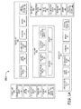
- Figures 1A-1D are block diagrams depicting exemplary embodiments of collaborative navigation systems 100 using optical pattern analysis to determine relative locations between a host unit and remote units. Each of Figures 1A-1D illustrates a different embodiment of collaborative navigation systems 100, labeled 100A-100D respectively.
- Figure 1A is a block diagram depicting an exemplary embodiment of a collaborative navigation system 100A using structured lighting pattern analysis at a remote unit.
- Exemplary collaborative navigation system 100A includes a host unit 102A and a plurality of remote units 104A. While four remote units 104A are shown in Figure 1A , other exemplary embodiments of system 100A include greater or fewer remote units 104A. In some exemplary embodiments, only a single remote unit 104A is included in system 100A.
- Host unit 102A includes a communication device 106, a positioning device 108, a projection surface 110, a processor 112, and a memory 114.
- Communication device 106 is operable to communicate with respective communications devices in the remote units 104A described below.
- the communications device includes a radio frequency (RF) radio and antenna, such as, but not limited to, a short range radio transceiver or a mobile telephone transceiver.
- the communication device 106 is operable to communicate data to/from similar communication devices on the remote units 104A.
- Positioning device 108 is operable to determine an absolute position and/or orientation of the host unit 102A.
- the positioning device 108 includes a satellite based navigation system, such as global navigation satellite systems (GNSS) (for example, global positioning system (GPS)).
- GNSS global navigation satellite systems
- GPS global positioning system
- the positioning device 108 includes terrestrial radio navigation systems, such as systems implementing Long Range Navigation (LORAN) or Very High Frequency Omnidirectional Range (VOR) and Distance Measuring Equipment (DME), or other low frequency radio transmissions used for navigation.
- LORAN Long Range Navigation
- VOR Very High Frequency Omnidirectional Range
- DME Distance Measuring Equipment
- Projection surface 110 is a surface which allows projection of a structured light pattern.
- projection surface 110 is substantially flat.
- the projection surface 110 is a predefined physical structure that would result in a predefined geo-location and unique lighting structure which can be easily detected by an image sensor (such as image sensor 118 described below).
- projection surface 110 is painted a specific color or shade to reduce interference or distortion of the structured light pattern.
- the structured light pattern is projected onto the projection surface 110 using an infrared or other non-visible light source.
- Processor 112 is communicatively coupled to the communication device 106 and the positioning device 108 and is used to control these devices and/or process data received from these devices.
- Memory 114 is communicatively coupled to processor 112 and is used to store program instructions for execution on processor 112 and is also used to store data received from communication device 106 and/or positioning device 108.
- Processor 112 is operable to cause communication device 106 to transmit the absolute position and/or orientation of the host unit 102A received from the positioning device 108 to the remote units 104A.
- Remote units 104A each include a communication device 116, an image sensor 118, an illumination source 120, a processor 122, and a memory 124.
- Communication device 116 is operable to communicate data to/from the communication device 106 of the host unit 102A.
- the communications device 116 includes a radio frequency (RF) radio and antenna, such as, but not limited to, a short range radio transceiver or a mobile telephone transceiver.
- RF radio frequency
- each remote unit 104A includes the same type of communication device.
- host unit 102A includes multiple communications devices 106 of different types that are each configured to communicate with a different subset of remote units 104A, each having a complimentary communication device 116 configured to communicate with an associated communication device 106 of the host unit 102A.
- Image sensor 118 is used to capture images of structured light patterns projected on the projection surface 110 of the host unit 102A.
- Illumination source 120 is used to project structured light patterns onto the projection surface 110 of the host unit 102A.
- the structured light patterns are projected onto the projection surface 110 from another remote unit 104A or from another source.
- the projection and image capture of the structured light patterns onto projection surfaces is described in detail below with reference to Figure 2A .
- the patterns are not structured light, but are instead painted onto a surface of the host unit 102A.
- Processor 122 is communicatively coupled to the communication device 116, the image sensor 118, and the illumination source 120 and is used to control these devices and/or process data received from these devices.
- Memory 124 is communicatively coupled to processor 122 and is used to store program instructions for execution on processor 122 and is also used to store data received from communication device 116, image sensor 118, and/or illumination source 120.
- Processor 122 is operable to compare aspects of the images of the structured light patterns projected onto the projection surface 110 of the host unit 102A with aspects of a predetermined pattern.
- the predetermined pattern is the pattern that is being transmitted on the projection surface 110 of the host unit 102A.
- the predetermined pattern is distorted and/or deformed as it is projected onto the projection surface 110 by the position and/or orientation of the projection surface 110 of the host unit 102A.
- Aspects that may be compared between the images and the predetermined pattern may be the size and position of elements in the pattern, the distance between elements of the pattern, or the distortion of elements of the pattern based on the angle of the projection surface 110 with respect to the image sensor 118 and/or the illumination source 120. This will be described in more detail with reference to Figure 2A and Figure 3 below.
- pattern recognition is used to determine the relative position and relative orientation between the image sensor 118 at the remote unit 104A and the pattern on the projection surface 110 at the host unit 102A.
- calculations are performed to determine how the pattern in the captured image is scaled, skewed, and translated from the predetermined pattern. The determination of how the image is scaled, skewed, and translated is used to determine the relative location and/or orientation between the image sensor 118 and the pattern on the projection surface 110.
- At least one predefined distorted pattern is registered a priori as associated to a predefined distance and/or angle between the host unit 102A and remote units 104A.
- the remote unit 104A moves around until a pattern captured by the image sensor 118 matches one of the predefined distorted patterns that were registered a priori.
- an exact match is not necessary and matching within a threshold constitutes a match.
- the host unit 104A moves around until a pattern captured by the image sensor 118 matches one of the predefined distorted patterns that were registered a priori.
- an exact match is not necessary and matching within a threshold constitutes a match.
- this pattern matching is less computationally intensive than pattern recognition techniques.
- Processor 122 determines at least one of a relative position and a relative orientation of each remote unit 104A relative to the host unit 102A based on the comparison of the aspects of the images of the structured light patterns with the aspects of the predetermined pattern.
- Processor 124 further determines at least one of an absolute position and/or absolute orientation of the remote unit 104A based on the relative position and/or relative orientation of the remote unit 104A relative to the host unit 102A and the absolute position and/or absolute orientation of the host unit 102A.
- relative X, Y, and Z coordinates between each remote unit 104A and the host unit 102A are summed to absolute X, Y, and Z coordinates of the host unit 102A to obtain the absolute X, Y, and Z coordinates of the particular remote unit 104A.
- the relative position of the remote unit 104A relative to the host unit 102A can be simplified to two-dimensional space (two distances on the X and Y axes).
- the relative orientation of the remote unit 104A relative to the host unit 102A is represented by relative roll, pitch, and heading (three relative rotations about the X, Y, and Z axes).
- the absolute orientation of the host unit 102A is represented by absolute roll, pitch, and heading (three absolute rotations about the X, Y, and Z axes).
- the relative roll, pitch, and heading for the remote unit 104A relative to the host unit 102A are summed with the absolute roll, pitch, and heading for the host unit 102A to obtain the absolute roll, pitch, and heading for the remote unit 104A (absolute rotations about the X, Y, and Z axes of the remote unit 104A), which represents the absolute orientation of the remote unit 104A.
- the relative orientation of the remote unit 104A relative to the host unit 102A can be simplified to two-dimensional space (two relative rotations about the X and Y axes).
- the exemplary collaborative navigation system 100A also includes inertial navigation sensors or other inertial navigation units that estimate the position and/or orientation in satellite navigation denied environments.
- the position estimates are periodically updated when satellite navigation information is available at the host unit and/or when both satellite navigation information is available at the host unit and the relative position and/or orientation information is calculated between the host unit and the remote unit.
- host unit 102A includes inertial navigation sensor 126 that estimates the position and/or orientation of the host unit 102A.
- processor 112 also implements a Kalman filter (or other estimator) to provide a navigation state update from information received from the positioning device 108, when available, to the position and/or orientation estimates to reduce accumulated navigation errors and to calibrate the inertial navigation sensor 126.
- Kalman filter or other estimator
- other types of sensor data is fused together or provided with navigation state updates by a Kalman filter (or other estimator) implemented by processor 112.
- each remote unit 104A includes an inertial navigation sensor 128 that estimates the position and/or orientation of the remote unit 104A.
- processor 122 also implements a Kalman filter (or other estimator) to provide a navigation state update based on the absolute position and/or orientation calculated for the remote units 104A using the image capture and analysis described above. This navigation state update is provided to the Kalman filter's (or other estimator's) position and/or orientation estimates to reduce accumulated navigation errors and to calibrate the inertial sensor 128.
- other types of sensor data is fused together or provided with navigation state updates by a Kalman filter (or other estimator) implemented by processor 112.
- the positioning device 108 does not have current absolute position and/or orientation information for the host unit 102A, such as when the positioning device is a GNSS (for example, GPS) and a GNSS signal is not available.
- GNSS for example, GPS
- the system could use a recursive approach to determine the absolute position and/or orientation of the host unit 102A.
- the host unit 102A moves to a position of one of the remote units 104A that was previously determined. Once the host unit 102A assumes the previous position of the remote unit 104A, the host unit sets its current position to be the position previously determined by the host unit for the remote unit 104A.
- the remote unit 104A can then be deployed using the host unit's knowledge of its absolute position as reference. Once the remote unit 104A has its new position calculated, the host unit 102A could then move to the new position of remote unit 104A and set its current location to be the position previously determined by the host unit for the remote unit 104A. This recursive approach of determination of remote unit location and the host unit 102A assuming the position of remote unit 104A can be repeated indefinitely. In exemplary embodiments, once the GNSS/GPS signal comes back, the host unit 104A can resume normal operation as before without relying on the recursive approach.
- the position determined by the GNSS/GPS receiver can be used as a state update for a Kalman filter or other state estimator.
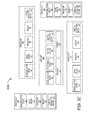
- Figure 1B is a block diagram depicting an exemplary embodiment of a collaborative navigation system 100B using structured lighting pattern analysis at a host unit.
- System 100B includes similar components to system 100A and operates according to similar principles and methods as system 100A described above.
- the primary difference between system 100B and system 100A is that in system 100B the host unit 102B has the image sensor 118 and the illumination source 120 and the remote units 104B have the projection surfaces 110 instead of the opposite configuration of system 100A.
- Exemplary collaborative navigation system 100B includes a host unit 102B and a plurality of remote units 104B. While four remote units 104B are shown in Figure 1A , other exemplary embodiments of system 100B include greater or fewer remote units 104B. In some exemplary embodiments, only a single remote unit 104B is included in system 100B.
- Host unit 102B includes the same components as host unit 102A, except for host unit 102B includes the image sensor 118 and the illumination source 120 instead of the projection surface 110.
- remote units 104B include all the same components as remote units 104B, except for remote units 104B include the projection surface 110 instead of the image sensor 118 and the illumination source 120.
- host unit 102B includes a communication device 106, a positioning device 108, a processor 112, and a memory 114.
- host unit 102B includes a communication device 106, a positioning device 108, a processor 112, and a memory 114.
- communication device 106, positioning device 108, processor 112, and memory 114 operate according to their description with reference to Figure 1A above.
- Image sensor 118 is used to capture images of structured light patterns projected on the projection surfaces 110 of each of the remote units 104B.
- Illumination source 120 is used to project structured light patterns onto the projection surfaces 110 of each of the remote units 104B.
- multiple image sensors 118 and/or illumination sources 120 are positioned at the host unit 102B to enable image capture and illumination of the plurality of projection surfaces 110 on the plurality of remote units 104B.
- the structured light patterns are projected onto the projection surfaces 110 from another remote unit 104B or from another source. The projection and image capture of the structured light patterns onto projection surfaces is described in detail below with reference to Figure 2A . In other exemplary embodiments described below, the patterns are not structured light, but are instead painted onto surfaces of the remote units 104B.
- Processor 112 is communicatively coupled to the communication device 106, the positioning device 108, the image sensor 118, and the illumination source 120 and is used to control these devices and/or process data received from these devices.
- Memory 114 is communicatively coupled to processor 112 and is used to store program instructions for execution on processor 112 and is also used to store data received from communication device 106, positioning device 108, image sensor 118, and/or illumination source 120.
- Processor 112 is operable to compare aspects of the images of the structured light patterns projected onto the projections surface 110 of the remote unit 104B with aspects of a predetermined pattern.
- the predetermined pattern is the pattern that is being projected onto the projection surface 110 of the remote units 104B.
- the predetermined pattern is distorted and/or deformed as it is projected onto the projection surface 110 by the position and/or orientation of the projection surface 110 of the remote units 104B.
- Aspects that may be compared between the images and the predetermined pattern may be the size of elements in the pattern, the distance between elements of the pattern, or the distortion of elements of the pattern based on the angle of the projection surface 110 with respect to the image sensor 118 and/or the illumination source 120. This will be described in more detail with reference to Figure 2A and Figure 3 below.
- pattern recognition is used to determine the relative position and relative orientation between the image sensor 118 at the host unit 102B and the pattern on the projection surface 110 at the projection unit 104B.
- calculations are performed to determine how the pattern in the captured image is scaled, skewed, and translated from the predetermined pattern. The determination of how the image is scaled, skewed, and translated is used to determine the relative location and/or orientation between the image sensor 118 and the pattern on the projection surface 110.
- At least one predefined distorted pattern is registered a priori as associated to a predefined distance and/or angle between the host unit 102B and remote units 104B.
- the remote unit 104B moves around until a pattern captured by the image sensor 118 matches one of the predefined distorted patterns that were registered a priori.
- an exact match is not necessary and matching within a threshold constitutes a match.
- the host unit 104B moves around until a pattern captured by the image sensor 118 matches one of the predefined distorted patterns that were registered a priori.
- an exact match is not necessary and matching within a threshold constitutes a match.
- this pattern matching is less computationally intensive than pattern recognition techniques.
- Processor 112 determines at least one of a relative position and a relative orientation of each remote unit 104B relative to the host unit 102B based on the comparison of the aspects of the images of the structured light patterns with the aspects of the predetermined pattern. Processor 112 further determines at least one of an absolute position and/or absolute orientation of the remote units 104B based on the relative position and/or relative orientation of the remote unit 104B relative to the host unit 104B and the absolute position and/or absolute orientation of the host unit 102B.
- relative X, Y, and Z coordinates between the remote unit 104B and the host unit 102B are summed to absolute X, Y, and Z coordinates of the host unit 102B to obtain the absolute X, Y, and Z coordinates of each remote unit 104B.
- the relative position of the remote unit 104B relative to the host unit 102B can be simplified to two-dimensional space (two distances on the X and Y axes).
- each remote unit 104B relative to the host unit 102B is represented by relative roll, pitch, and heading (three relative rotations about the X, Y, and Z axes).
- the absolute orientation of the host unit 102B is represented by absolute roll, pitch, and heading (three absolute rotations about the X, Y, and Z axes).
- the relative roll, pitch, and heading for a remote unit 104B relative to the host unit 102B are summed with the absolute roll, pitch, and heading for the host unit 102B to obtain the absolute roll, pitch, and heading for the remote unit 104B (absolute rotations about the X, Y, and Z axes of the remote unit 104B), which represents the absolute orientation of the remote unit 104B.
- the relative orientation of the remote unit 104B relative to the host unit 102B can be simplified to two-dimensional space (two relative rotations about the X and Y axes).
- the absolute position and/or orientation of the remote units 104B are calculated at the processor 112 of the host unit 102B.
- the absolute position and/or orientation of each remote unit 104B is then transmitted to each remote unit 104B from the host unit 102B using the communication device 106.
- the absolute position and/or orientation of the remote units 104B are calculated at each respective processor 122 after both (1) the relative position and/or orientation between the host unit 102B and each respective remote unit 104B; and (2) the absolute position and/or orientation of the host unit 102B are communicated to the respective remote unit 104B from the host unit 102B using communication device 106 and communication device 116.
- the exemplary collaborative navigation system 100B also includes inertial navigation sensors or other inertial navigation units that estimate the position and/or orientation in satellite navigation denied environments.
- the position estimates are periodically updated when satellite navigation information is available at the host unit and/or when both satellite navigation information is available at the host unit and the relative position and/or orientation information is calculated between the host unit and the remote unit.
- host unit 102B includes inertial navigation sensor 126 that estimates the position and/or orientation of the host unit 102B.
- processor 112 also implements a Kalman filter (or other estimator) to provide a navigation state update from information received from the positioning device 108, when available, to the position and/or orientation estimates to reduce accumulated navigation errors and to calibrate the inertial navigation sensor 126.
- Kalman filter or other estimator
- other types of sensor data is fused together or provided with navigation state updates by a Kalman filter (or other estimator) implemented by processor 112.
- each remote unit 104B includes an inertial navigation sensor 128 that estimates the position and/or orientation of the remote unit 104B.
- processor 122 also implements a Kalman filter (or other estimator) to provide a navigation state update based on the absolute position and/or orientation calculated for the remote units 104B using the image capture and analysis described above. This navigation state update is provided to the Kalman filter's (or other estimator's) position and/or orientation estimates to reduce accumulated navigation errors and to calibrate the inertial sensor 128.
- other types of sensor data is fused together or provided with navigation state updates by a Kalman filter (or other estimator) implemented by processor 112.
- the positioning device 108 does not have current absolute position and/or orientation information for the host unit 102B, such as when the positioning device is a GNSS (for example, GPS) and a GNSS signal is not available.
- GNSS for example, GPS
- the system could use a recursive approach to determine the absolute position and/or orientation of the host unit 102B.
- the host unit 102B moves to a position of one of the remote units 104B that was previously determined. Once the host unit 102B assumes the previous position of the remote unit 104B, the host unit sets its current position to be the position previously determined by the host unit for the remote unit 104B.
- the remote unit 104B can then be deployed using the host unit's knowledge of its absolute position as reference. Once the remote unit 104B has its new position calculated, the host unit 102B could then move to the new position of remote unit 104B and set its current location to be the position previously determined by the host unit for the remote unit 104B. This recursive approach of determination of remote unit location and the host unit 102B assuming the position of remote unit 104B can be repeated indefinitely. In exemplary embodiments, once the GNSS/GPS signal comes back, the host unit 104B can resume normal operation as before without relying on the recursive approach.
- the position determined by the GNSS/GPS receiver can be used as a state update for a Kalman filter or other state estimator.
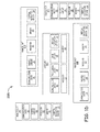
- Figure 1C is a block diagram depicting an exemplary embodiment of a collaborative navigation system 100C using pattern analysis at a remote unit.
- System 100C includes similar components to system 100A and operates according to similar principles and methods as system 100A described above. The primary difference between system 100C and system 100A is that system 100C uses painted patterns instead of structure light patterns projected onto surfaces.
- Exemplary collaborative navigation system 100C includes a host unit 102C and a plurality of remote units 104C. While four remote units 104C are shown in Figure 1C , other exemplary embodiments of system 100C include greater or fewer remote units 104C. In some exemplary embodiments, only a single remote unit 104C is included in system 100C.
- Host unit 102C includes all the same components as host unit 102A, except for host unit 102C includes a painted surface 130 instead of including a projection surface 110.
- remote units 104C include all the same components as remote units 104A, except for remote units 104C do not include illumination source 120 because the patterns are not projected and are instead integrated into painted surface 130.
- host unit 102C includes a communication device 106, a positioning device 108, a painted surface 130, a processor 112, and a memory 114.
- host unit 102C includes a communication device 106, a positioning device 108, a painted surface 130, a processor 112, and a memory 114.
- communication device 106, positioning device 108, processor 112, and memory 114 operate according to their description with reference to Figure 1A above.
- Painted surface 130 of host unit 102C is similar to projection surface 110 of host unit 102A.
- the primary difference between painted surface 130 and projection surface 110 is that painted surface 130 includes painted patterns that are integrated into painted surface 130 in contrast to projection surface 110 operable to have structured light patterns projected onto it.
- painted surface 130 is substantially flat.
- the painted surface 130 is a specific structured surface that constitutes a specific recognized pattern when processed by the image sensor 118 as described below.
- the patterns are painted onto painted surface 130 using specific contrasting colors or shades to enable the most accurate image analysis of the painted pattern.
- the painted patterns are not visible to the eye and require infrared image sensors or other non-visible light image sensors to capture images of the patterns.
- the patterns are created through other processes, such as by engraving, scraping, positioning objects, removing or adding material to a surface, or through other ways that could be distinguished, recognized, and/or matched by a robotic vision system.
- each remote unit 104C includes a communication device 116, an image sensor 118, a processor 122, and a memory 124.
- Each of communication device 116, processor 122, and memory 124 operate according to their description with reference to Figure 1A above.
- Image sensor 118 of remote unit 104C is configured to capture images of painted patterns integrated into painted surface 130. Because image sensor 118 is configured to capture images of painted patterns integrated into painted surface 130 instead of a projected structured light pattern on a projection surface 110, remote units 104C do not include illumination sources 120 to project structured light patterns. In other exemplary embodiments, other illumination sources are used to improve the environment lux level for the image sensor 118 for times of low or other non-ideal lighting, without projecting structured light patterns.
- Processor 122 operates as described above to compare aspects of the images of the patterns to aspects of a predetermined pattern.
- the predetermined pattern is the pattern that is painted onto the painted surface 130.
- the image of the predetermined pattern is distorted and/or deformed by the position and/or orientation of the painted surface 130 in the images captured by image sensor 118.
- Aspects that may be compared between the images and the predetermined pattern may be the size of elements in the pattern, the distance between elements of the pattern, or the distortion of elements of the pattern based on the angle and/or rotation of the painted surface 130 with respect to the image sensor 118. This will be described in more detail with reference to Figure 2B and Figure 3 below.
- pattern recognition is used to determine the relative position and relative orientation between the image sensor 118 at the remote unit 104C and the pattern on the painted surface 130 at the host unit 102C.
- calculations are performed to determine how the pattern in the captured image is scaled, skewed, and translated from the predetermined pattern. The determination of how the image is scaled, skewed, and translated is used to determine the relative location and/or orientation between the image sensor 118 and the pattern on the painted surface 130.
- At least one predefined distorted pattern is registered a priori as associated to a predefined distance and/or angle between the host unit 102C and remote units 104C.
- the remote unit 104C moves around until a pattern captured by the image sensor 118 matches one of the predefined distorted patterns that were registered a priori.
- an exact match is not necessary and matching within a threshold constitutes a match.
- the host unit 104C moves around until a pattern captured by the image sensor 118 matches one of the predefined distorted patterns that were registered a priori.
- an exact match is not necessary and matching within a threshold constitutes a match.
- this pattern matching is less computationally intensive than pattern recognition techniques.
- processor 122 determines a relative position and/or relative orientation of the remote unit 104C relative to the host unit 102C as described above. Based on the relative position and/or relative orientation of the remote unit 104C relative to the host unit 102C, processor 124 further determines at least one of an absolute position and/or absolute orientation of the remote unit 104C based on the relative position and/or relative orientation of the remote unit 104C and the absolute position and/or absolute orientation of the host unit 102C.
- relative X, Y, and Z coordinates between the remote unit 104C and the host unit 102C are summed to absolute X, Y, and Z coordinates of the particular remote unit 104C.
- the relative position of the remote unit 104C relative to the host unit 102C can be simplified to two-dimensional space (two distances on the X and Y axes).
- the relative orientation of the remote unit 104C relative to the host unit 102C is represented by relative roll, pitch, and heading (three relative rotations about the X, Y, and Z axes).
- the absolute orientation of the host unit 102A is represented by absolute roll, pitch, and heading (three absolute rotations about the X, Y, and Z axes).
- the relative roll, pitch, and heading for the remote unit 104C relative to the host unit 102C are summed with the absolute roll, pitch, and heading for the host unit 102C to obtain the absolute roll, pitch, and heading for the remote unit 104C (absolute rotations about the X, Y, and Z axes of the remote unit 104C), which represents the absolute orientation of the remote unit 104C.
- the relative orientation of the remote unit 104C relative to the host unit 102C can be simplified to two-dimensional space (two relative rotations about the X and Y axes).
- the exemplary collaborative navigation system 100C also includes inertial navigation sensors or other inertial navigation units that estimate the position and/or orientation in satellite navigation denied environments.
- the position estimates are periodically updated when satellite navigation information is available at the host unit and/or when both satellite navigation information is available at the host unit and the relative position and/or orientation information is calculated between the host unit and the remote unit.
- host unit 102C includes inertial navigation sensor 126 that estimates the position and/or orientation of the host unit 102C.
- processor 112 also implements a Kalman filter (or other estimator) to provide a navigation state update from information received from the positioning device 108, when available, to the position and/or orientation estimates to reduce accumulated navigation errors and to calibrate the inertial navigation sensor 126.
- Kalman filter or other estimator
- other types of sensor data is fused together or provided with navigation state updates by a Kalman filter (or other estimator) implemented by processor 112.
- each remote unit 104C includes an inertial navigation sensor 128 that estimates the position and/or orientation of the remote unit 104C.
- processor 122 also implements a Kalman filter (or other estimator) to provide a navigation state update based on the absolute position and/or orientation calculated for the remote units 104C using the image capture and analysis described above. This navigation state update is provided to the Kalman filter's (or other estimator's) position and/or orientation estimates to reduce accumulated navigation errors and to calibrate the inertial sensor 128.
- other types of sensor data is fused together or provided with navigation state updates by a Kalman filter (or other estimator) implemented by processor 112.
- the positioning device 108 does not have current absolute position and/or orientation information for the host unit 102C, such as when the positioning device is a GNSS (for example, GPS) and a GNSS signal is not available.
- GNSS for example, GPS
- the system could use a recursive approach to determine the absolute position and/or orientation of the host unit 102C.
- the host unit 102C moves to a position of one of the remote units 104C that was previously determined. Once the host unit 102C assumes the previous position of the remote unit 104C, the host unit sets its current position to be the position previously determined by the host unit for the remote unit 104C.
- the remote unit 104C can then be deployed using the host unit's knowledge of its absolute position as reference. Once the remote unit 104C has its new position calculated, the host unit 102C could then move to the new position of remote unit 104C and set its current location to be the position previously determined by the host unit for the remote unit 104C. This recursive approach of determination of remote unit location and the host unit 102C assuming the position of remote unit 104C can be repeated indefinitely. In exemplary embodiments, once the GNSS/GPS signal comes back, the host unit 104C can resume normal operation as before without relying on the recursive approach.
- the position determined by the GNSS/GPS receiver can be used as a state update for a Kalman filter or other state estimator.
- Figure 1D is a block diagram depicting an exemplary embodiment of a collaborative navigation system 100D using pattern analysis at a host unit.
- System 100D includes similar components to systems 100B and operates according to similar principles and methods as system 100B described above. The primary difference between system 100D and system 100B is that system 100D uses painted patterns instead of structured light patterns projected onto surfaces.
- Exemplary collaborative navigation system 100D includes a host unit 102D and a plurality of remote units 104D. While four remote units 104D are shown in Figure 1D , other exemplary embodiments of system 100D include greater or fewer remote units 104D. In some exemplary embodiments, only a single remote unit 104D is included in system 100D.
- each remote unit 104D includes a communication device 112, a painted surface 130, a processor 106, and a memory 106.
- Each of communication device 112, processor 122, and memory 124 operate according to their description with reference to Figure 1B above.
- Painted surface 130 of each remote unit 104D is similar to projection surface 110 of each remote unit 104B.
- the primary difference between painted surface 130 and projection surface 110 is that painted surface 130 includes painted patterns that are integrated into painted surface 130 in contrast to projection surface 110 operable to have structured light patterns projected onto it.
- painted surface 130 is substantially flat.
- the painted surface 130 is a specific structured surface that constitutes a specific recognized pattern when processed by the image sensor 118 as described below.
- the patterns are painted onto painted surface 130 using specific contrasting colors or shades to enable the most accurate image analysis of the painted pattern.
- the painted patterns are not visible to the eye and require infrared image sensors or other non-visible light image sensors to capture images of the patterns.
- the patterns are created through other processes, such as by engraving, scraping, positioning objects, removing or adding material to a surface, or through other ways that could be distinguished by a robotic vision system.
- Host unit 102D includes all the same components as host unit 102B, except for host unit 102D includes a painted surface 130 instead of including a projection surface 110.
- remote units 104D include all the same components as remote units 104B, except for remote units 104D do not include illumination source 120 because the patterns are not projected and are instead integrated into painted surface 130.
- host unit 102D includes a communication device 106, a positioning device 108, an image sensor 118, a processor 112, and a memory 114.
- host unit 102D includes a communication device 106, a positioning device 108, an image sensor 118, a processor 112, and a memory 114.
- communication device 106, positioning device 108, image sensor 118, processor 112, and memory 114 operate according to their description with reference to Figure 1B above.
- Image sensor 118 of host unit 102D is configured to capture images of painted patterns integrated into painted surfaces 118. Because image sensor 118 is configured to capture images of painted patterns integrated into painted surface 130 instead of a projected structured light pattern on a projection surface 110, remote units 104C do not include illumination sources 120 to project structured light patterns.
- Processor 112 operates as described above to compare aspects of the images of the patterns to aspects of a predetermined pattern.
- the predetermined pattern is the pattern that is painted onto the painted surface 130.
- the image of the predetermined pattern is distorted and/or deformed by the position and/or orientation of the painted surface 130 in the images captured by image sensor 118.
- Aspects that may be compared between the images and the predetermined pattern may be the size of elements in the pattern, the distance between elements of the pattern, or the distortion (such as deformation) of elements of the pattern based on the angle and/or rotation of the painted surface 130 with respect to the image sensor 118. This will be described in more detail with reference to Figure 2B and Figure 3 below.
- pattern recognition is used to determine the relative position and relative orientation between the image sensor 118 at the host unit 102D and the pattern on the painted surface 130 at the projection unit 104D.
- calculations are performed to determine how the pattern in the captured image is scaled, skewed, and translated from the predetermined pattern. The determination of how the image is scaled, skewed, and translated is used to determine the relative location and/or orientation between the image sensor 118 and the pattern on painted surface 130.
- At least one predefined distorted pattern is registered a priori as associated to a predefined distance and/or angle between the host unit 102D and remote units 104D.
- the remote unit 104D moves around until a pattern captured by the image sensor 118 matches one of the predefined distorted patterns that were registered a priori.
- an exact match is not necessary and matching within a threshold constitutes a match.
- the host unit 104D moves around until a pattern captured by the image sensor 118 matches one of the predefined distorted patterns that were registered a priori.
- an exact match is not necessary and matching within a threshold constitutes a match.
- this pattern matching is less computationally intensive than pattern recognition techniques.
- each remote unit 104B relative to the host unit 102B is represented by relative roll, pitch, and heading (three relative rotations about the X, Y, and Z axes).
- the absolute orientation of the host unit 102B is represented by absolute roll, pitch, and heading (three absolute rotations about the X, Y, and Z axes).
- the relative roll, pitch, and heading for a remote unit 104B relative to the host unit 102B are summed with the absolute roll, pitch, and heading for the host unit 102B to obtain the absolute roll, pitch, and heading for the remote unit 104B (absolute rotations about the X, Y, and Z axes of the remote unit 104B), which represents the absolute orientation of the remote unit 104B.
- the relative position of the remote unit 104A relative to the host unit 102A can be simplified to two-dimensional space (two distances on the X and Y axes) and the relative orientation of the remote unit 104D relative to the host unit 102D can be simplified to two-dimensional space (two relative rotations about the X and Y axes).
- the absolute position and/or orientation of the remote units 104D are calculated at the processor 112 of the host unit 102D.
- the absolute position and/or orientation of each remote unit 104B is then transmitted to each remote unit 104D from the host unit 102D using the communication device 106.
- the absolute position and/or orientation of the remote units 104D are calculated at each respective processor 122 after both (1) the relative position and/or orientation between the host unit 102B and each respective remote unit 104D; and (2) the absolute position and/or orientation of the host unit 102D are communicated to the respective remote unit 104D from the host unit 102D using communication device 106 and communication device 116.
- the exemplary collaborative navigation system 100D also includes inertial navigation sensors or other inertial navigation units that estimate the position and/or orientation in satellite navigation denied environments.
- the position estimates are periodically updated when satellite navigation information is available at the host unit and/or when both satellite navigation information is available at the host unit and the relative position and/or orientation information is calculated between the host unit and the remote unit.
- host unit 102D includes inertial navigation sensor 126 that estimates the position and/or orientation of the host unit 102D.
- processor 112 also implements a Kalman filter (or other estimator) to provide a navigation state update from information received from the positioning device 108, when available, to the position and/or orientation estimates to reduce accumulated navigation errors and to calibrate the inertial navigation sensor 126.
- Kalman filter or other estimator
- other types of sensor data is fused together or provided with navigation state updates by a Kalman filter (or other estimator) implemented by processor 112.
- each remote unit 104D includes an inertial navigation sensor 128 that estimates the position and/or orientation of the remote unit 104D.
- processor 122 also implements a Kalman filter (or other estimator) to provide a navigation state update based on the absolute position and/or orientation calculated for the remote units 104D using the image capture and analysis described above. This navigation state update is provided to the Kalman filter's (or other estimator's) position and/or orientation estimates to reduce accumulated navigation errors and to calibrate the inertial sensor 128.
- other types of sensor data is fused together or provided with navigation state updates by a Kalman filter (or other estimator) implemented by processor 112.
- the positioning device 108 does not have current absolute position and/or orientation information for the host unit 102D, such as when the positioning device is a GNSS (for example, GPS) and a GNSS signal is not available.
- GNSS for example, GPS
- the system could use a recursive approach to determine the absolute position and/or orientation of the host unit 102D.
- the host unit 102D moves to a position of one of the remote units 104D that was previously determined. Once the host unit 102D assumes the previous position of the remote unit 104D, the host unit sets its current position to be the position previously determined by the host unit for the remote unit 104D.
- the remote unit 104D can then be deployed using the host unit's knowledge of its absolute position as reference. Once the remote unit 104D has its new position calculated, the host unit 102D could then move to the new position of remote unit 104D and set its current location to be the position previously determined by the host unit for the remote unit 104D. This recursive approach of determination of remote unit location and the host unit 102D assuming the position of remote unit 104D can be repeated indefinitely. In exemplary embodiments, once the GNSS/GPS signal comes back, the host unit 104D can resume normal operation as before without relying on the recursive approach.
- the position determined by the GNSS/GPS receiver can be used as a state update for a Kalman filter or other state estimator.
- Figures 2A-2B are diagrams depicting exemplary embodiments of image sensor configurations used in the optical pattern analysis performed by the systems of Figures 1A-1D . Each of Figures 2A-2B illustrates a different image sensor configuration 200, labeled 200A-200B respectively.
- Figure 2A is a block diagram depicting an exemplary embodiment of an image sensor configuration 200A using structured lighting pattern analysis including an image sensor 202, a projection surface 204, and an illumination source 206.
- the image sensor configuration 200A shown in Figure 2A could be used in either the collaborative navigation system 100A shown in Figure 1A or the collaborative navigation system 100B shown in Figure 1B .
- Image sensor 202 is used to capture images of at least one structured light pattern 208 projected on the projection surface 204 by illumination source 206.
- the at least one structured light pattern 208 projected by the illumination source 206 onto projection surface 204 is a known patterns of pixels with known geometries, such as a grid, horizontal bars, or vertical bars.
- the image sensor 202 captures images of the known structured light pattern 208 with the known geometries.
- the projection surface 204 is flat. In other exemplary embodiments, the projection surface 204 has other shapes.
- the relative orientation and position of the image sensor 202 relative to the projection surface 204 can then be calculated using computer vision systems by analyzing the difference in the geometries of the captured representation of the structured light pattern 208 in the captured images and the known geometry of the structured light pattern 208.
- at least one lens 210 is positioned between the image sensor 202 and the projection surface 204 to focus the light onto the image sensor 202.
- at least one optional grating 212 is positioned between the image sensor 202 and the lens 210.
- the optional grating 212 improves detection of the structured light pattern 208.
- the configuration between the lens 210 and the optional grating 212 is different.
- other optical elements are included in the image sensor portion of the image sensor configuration 200A.
- the pattern 208 is projected using at least one pattern template 214 positioned between the illumination source 206 and the projection surface 204.
- the pattern template is a grating.
- the pattern 208 is projected in other ways.
- at least one lens 216 is positioned between the illumination source 206 and the projection surface 204 to focus the light from the illumination source 206 onto the projection surface 208.
- the configuration between the pattern template 214 and the lens 216 is different.
- other optical elements are included in the projection portion of the image sensor configuration 200A.
- This process of determining position and attitude can be degraded when the viewing angle between the image sensor 202 and the structured light pattern 208 on the projection surface 204 becomes large.
- This degradation can be overcome by including several surfaces 204 in the sensor configuration 200A positioned at different angles relative to the nominal surface.
- a plurality of projection surfaces 110 are positioned at different angles relative to the nominal surface.
- the angular rotation and position offset can be encoded into the painted structure, so the user's navigation system can make the necessary computations to compensate for the various surface angles and positions.
- Figure 2B is a block diagram depicting an exemplary embodiment of an image sensor configuration 200B using pattern analysis including an image sensor 202 and a painted surface 214.
- the image sensor configuration 200B shown in Figure 2B could be used in either the collaborative navigation system 100C shown in Figure 1C or the collaborative navigation system 100D shown in Figure 1D .
- image sensor 202 is used to capture images of at least one painted pattern 212 on the painted surface 214.
- the at least one painted pattern 212 is painted onto the painted surface 214.
- painted patterns 214 are created through other processes, such as by engraving, scraping, positioning objects, removing or adding material to a surface, or through other ways that could be distinguished by a robotic vision system.
- the at least one painted pattern 212 is a known pattern with known geometries, such as a grid, horizontal bars, or vertical bars.
- the image sensor 202 captures images of the known painted pattern 212 with the known geometries.
- the painted surface 214 is flat. In other exemplary embodiments, the painted surface 214 has other shapes.
- the relative orientation and position of the image sensor 202 relative to the painted surface 214 can then be calculated using computer vision systems by analyzing the difference in the geometries of the captured representation of the painted pattern 212 as captured in the captured images and the known geometry of the painted pattern 212.
- the at least one lens 210 is positioned between the image sensor 202 and the painted surface 214 to focus the light onto the image sensor 202.
- the at least one optional grating 212 is positioned between the image sensor 202 and the lens 210.
- the optional grating 212 improves detection of the painted pattern 212.
- the configuration between the lens 210 and the optional grating 212 is different.
- other optical elements are included in the image sensor portion of the image sensor configuration 200A.
- the results of this process of determining position and attitude can be degraded when the viewing angle between the image sensor 202 and the painted pattern 212 on the painted surface 214 becomes large. This degradation can be overcome by providing several painted surfaces 212 in the sensor configuration 200B positioned at different angles relative to the nominal surface.
- a plurality of painted surfaces 212 are positioned at different angles relative to the nominal surface.
- the angular rotation and position offset can be encoded into the painted structure, so the user's navigation system can make the necessary computations to compensate for the various surface angles and positions.
- image sensor configuration 200A is combined with image sensor configuration 200B to create an image sensor configuration that includes both structured light patterns 208 and painted patterns 214.
- Figure 3 is a diagram depicting an exemplary embodiment of an image 300 of a captured pattern 304 on a surface 302 with an overlay of a known pattern 306 used in the optical pattern analysis performed by collaborative navigation systems 100A, 100B, 100C, and 100D shown in Figures 1A , 1B , 1C , and 1D respectively.
- Figure 3 shows an image 300 of a surface 302 having a captured pattern 304 on it.
- the captured pattern 304 is represented by dark squares that are distorted based on the position and/or orientation of the surface 302 relative to the image sensor capturing the image 300 (such as, but not limited to, image sensor 118 or image sensor 202 described above).
- Various geometries of the captured pattern 304 can be extracted from the image 300 of the captured pattern 304 captured by the image sensor.
- a known pattern 306 is also overlayed on top of the captured pattern 304 in Figure 3 to show the geometries of the known pattern 306 compared to the geometries of the captured pattern 304 in image 300.
- the known pattern 306 has known geometries.
- a processor such as, but not limited to, processors 112 or 122 described above
- optical pattern analysis can determine the relative position between the surface 302 in the image 300 and the image sensor capturing the image 300.
- the captured pattern 304 includes a plurality of captured pattern elements 308 distributed throughout the captured pattern 304.
- the known pattern 306 includes a plurality of known pattern elements 310 distributed throughout the known pattern 306.
- each captured pattern element 308 of the captured pattern 304 corresponds to a known pattern element 310 of the known pattern 306.
- the size, shape, and position of the plurality of captured pattern elements 308 and the spacing between the plurality of captured pattern elements 308 can be extracted from the image 300.
- the size, shape, and position of the plurality of known pattern elements 310 and the spacing between the plurality of known pattern elements 310 is known.
- the size, shape, and position of captured pattern elements 308 can be compared to the size, shape, and position of the known pattern elements 310 to help determine the relative position and orientation between the surface 302 in the image 300 and the image sensor capturing the image 300.
- the spacing between captured pattern elements 308 can be compared to the spacing between the known pattern elements 310 to help determine the relative position and orientation between the surface 302 in the image 300 and the image sensor capturing the image 300.
- only a subset of the size, shape, and position of the pattern elements and the spacing between the pattern elements are used to determine the relative position and orientation between the surface 302 in the image 300 and the image sensor capturing the image 300.
- a first height H1 represents the height of a captured pattern element 308, while a second height H3 represents the height of a corresponding known pattern element 310.
- a first width W1 represents the width of a captured pattern element 308, while a second width W3 represents the width of a corresponding known pattern element 310.
- the shape of the pattern elements 308 may be distorted due to pixel blurring and contrast merge causing the first height H1, the second height H3, the first width W1, and the second width W3 to be inaccurate.
- the analysis can still be accurate if the relationship between the distances D1 and D5 and distances D3 and D7 can be analyzed without analyzing the first height H1, the second height H3, the first width W1, and the second width W3.
- a first distance D1 represents the distance between a first captured pattern element 308 and a second captured pattern element 308, while a second distance D3 represents the distance between a first known pattern element 310 corresponding to the first captured pattern element 308 and a second known pattern element 310 corresponding to the second captured pattern element 308.
- a third distance D5 represents the distance between a first captured pattern element 308 and a third captured pattern element 308, while a fourth distance D7 represents the distance between a first known pattern element 310 corresponding to the first captured pattern element 308 and a third known pattern element 310 corresponding to the third captured pattern element 308.
- a first X position X1 represents the X position of a captured pattern element 308, while a second X position X2 represents the X position of a corresponding known pattern element 310.
- a first Y position Y1 represents the Y position of a captured pattern element 308, while a second Y position Y2 represents the Y position of a corresponding known pattern element 310.
- At least a subset of the corresponding measurements are compared and/or analyzed between the captured pattern elements 308 of the captured pattern 304 and the corresponding known pattern elements 310 of the known pattern 306 to determine the relative position and/or orientation between the image sensor and the captured pattern 304.
- the matching predefined distorted pattern would closely match captured pattern 304.
- the known pattern 306 is pre-distorted to create the predefined distorted pattern associated with a particular distance and/or angle from the surface 302. This predefined distorted pattern can then be registered a priori as associated to the predefined distance and/or angle. Additional pre-distortions of the known pattern 306 can be created to create additional predefined distorted patterns associated with various distances and/or angles between the imaging sensor and the surface 302. Then, as described above, a remote unit or host unit can move around testing the various predefined distorted patterns until it find one that matches within a threshold.
- Figures 4A-4B are flow charts illustrating example methods 400 for performing the optical pattern analysis of a pattern according to embodiments of the present invention. Each of Figures 4A-4B illustrates a different embodiment of the method 400, labeled 400A-400B.
- Figure 4A is a flow chart illustrating one embodiment of a method 400A for performing optical pattern analysis of a pattern using structured lighting pattern analysis.
- a pattern is projected onto a surface.
- the pattern is projected using the illumination source 120 of collaborative navigation system 100A positioned at the remote unit 104A, the illumination source 120 of collaborative navigation system 100B positioned at the host unit 102B, or the illumination source 206 of the image sensor configuration 200A.
- the pattern is projected onto the projection surface 110 of collaborative navigation system 100A positioned at the host unit 102A, the projection surface 110 of collaborative navigation system 100B positioned at the remote unit 104B, or the projection surface 204 of the image sensor configuration 200A.
- an image of the pattern is captured from the surface.
- the image of the pattern is captured from the projection surface 110 positioned at the host unit 102A by the image sensor 118 of collaborative navigation system 100A positioned at the remote unit 104A, from the projection surface 110 positioned at the remote unit 104B by the image sensor 118 of collaborative navigation system 100B positioned at the host unit 102B, or from the projection surface 204 by the image sensor 202 of the image sensor configuration 200A.
- aspects of the image of the pattern are compared with aspects of a known pattern.
- aspects of the image of the pattern are compared with aspects of the known pattern using processor 122 of remote unit 104A of collaborative navigation system 100A or processor 112 of host unit 104B of collaborative navigation system 100B.
- pattern matching is used to compare the aspects and determine whether the image captured at a particular position matches any predefined distorted patterns associated with particular distances and/or angles.
- pattern recognition is used to determine the actual distances and/or angles between the known pattern and the pattern in the captured image.
- a relative position and/or relative orientation of a remote unit relative to a host unit is determined based on the comparison at block 406.
- the relative position and/or relative orientation of the remote unit relative to the host unit is determined using processor 122 of remote unit 104A of collaborative navigation system 100A or processor 112 of host unit 104B of collaborative navigation system 100B.
- a first absolute position and/or first absolute orientation of the host unit is received.
- the first absolute position and/or first absolute orientation of the host unit is received using the positioning device 108 of host unit 102A of collaborative navigation system 100A or the positioning device 108 of host unit 102B of collaborative navigation system 100B.
- a second absolute position and/or absolute orientation of the remote unit is determined based on the relative position and/or relative orientation of the remote unit relative to the host unit and the absolute position and/or orientation of the host unit.
- the second absolute position and/or absolute orientation of the remote unit is determined using processor 122 of remote unit 104A of collaborative navigation system 100A, processor 112 of host unit 104B of collaborative navigation system 100B, or processor 122 of remote unit 104B of collaborative navigation system 100B.
- Figure 4B is a flow chart illustrating one embodiment of a method 400B for performing optical pattern analysis of a pattern using pattern analysis.
- method 400B of Figure 4B does not require block 402 required by method 400A of Figure 4B because the image pattern is not projected onto a surface. Instead, the image pattern is already on the surface and method 400B begins at block 404, by capturing an image of the pattern from the surface.
- the image of the pattern is captured from the projection surface 110 positioned at the host unit 102C by the image sensor 118 of collaborative navigation system 100C positioned at the remote unit 104C, from the projection surface 110 positioned at the remote unit 104D by the image sensor 118 of collaborative navigation system 100D positioned at the host unit 102D, or from the projection surface 214 by the image sensor 202 of the image sensor configuration 200B.
- aspects of the image of the pattern are compared with aspects of a known pattern.
- the relative position and/or relative orientation of the remote unit relative to the host unit is determined using processor 122 of remote unit 104C of collaborative navigation system 100C or processor 112 of host unit 104D of collaborative navigation system 100D.
- pattern matching is used to compare the aspects and determine whether the image captured at a particular position matches any predefined distorted patterns associated with particular distances and/or angles.
- pattern recognition is used to determine the actual distances and/or angles between the known pattern and the pattern in the captured image.
- a relative position and/or relative orientation of a remote unit relative to a host unit is determined based on the comparison at block 406.
- the relative position and/or relative orientation of the remote unit relative to the host unit is determined using processor 122 of remote unit 104C of collaborative navigation system 100C or processor 112 of host unit 104D of collaborative navigation system 100D.
- a first absolute position and/or first absolute orientation of the host unit is received.
- the first absolute position and/or first absolute orientation of the host unit is received using the positioning device 108 of host unit 102C of collaborative navigation system 100C or the positioning device 108 of host unit 102D of collaborative navigation system 100D.
- a second absolute position and/or absolute orientation of the remote unit is determined based on the relative position and/or relative orientation of the remote unit relative to the host unit and the absolute position and/or orientation of the host unit.
- the second absolute position and/or absolute orientation of the remote unit is determined using processor 122 of remote unit 104C of collaborative navigation system 100C, processor 112 of host unit 104D of collaborative navigation system 100D, or processor 122 of remote unit 104D of collaborative navigation system 100D.
- a processor (such as, but not limited to, processor 112 and processor 122 described above with reference to Figures 1A-1D ) includes or functions with software programs, firmware or other computer readable instructions for carrying out various methods, process tasks, calculations, and control functions, used in the collaborative navigation systems using optical pattern analysis to determine relative locations between a host unit and a remote unit and methods for performing the optical pattern analysis of a pattern according to embodiments of the present invention.
- These instructions are typically stored on any appropriate computer readable medium (such as, but not limited to, memory 114 and memory 124 described above with reference to Figures 1A-1D ) used for storage of computer readable instructions or data structures.
- the computer readable medium can be implemented as any available media that can be accessed by a general purpose or special purpose computer or processor, or any programmable logic device.
- Suitable processor-readable media may include storage or memory media such as magnetic or optical media.
- storage or memory media may include conventional hard disks, Compact Disk - Read Only Memory (CD-ROM), volatile or non-volatile media such as Random Access Memory (RAM) (including, but not limited to, Synchronous Dynamic Random Access Memory (SDRAM), Double Data Rate (DDR) RAM, RAMBUS Dynamic RAM (RDRAM), Static RAM (SRAM), etc.), Read Only Memory (ROM), Electrically Erasable Programmable ROM (EEPROM), and flash memory, etc.
- RAM Random Access Memory
- SDRAM Synchronous Dynamic Random Access Memory
- DDR Double Data Rate
- RDRAM RAMBUS Dynamic RAM
- SRAM Static RAM
- ROM Read Only Memory
- EEPROM Electrically Erasable Programmable ROM
- flash memory etc.
- Suitable processor-readable media may also include transmission media such as electrical, electromagnetic, or digital signals, conveyed via a communication medium such as a network and/or a wireless link.
- Example 1 includes a navigation system comprising: a host unit having: a positioning device operable to determine at least one of a first absolute position and a first absolute orientation of the host unit; a first communication device operable to communicate signals; a first processor; and a first memory; a remote unit having: a second communication device operable to receive the signals from the first communication device; a second processor; and a second memory; wherein at least one of the first processor and the second processor is operable to compare first aspects of a known pattern with second aspects of an image of a captured pattern positioned on a surface at at least one of the host unit and the remote unit; wherein at least one of the first processor and the second processor is operable to determine at least one of a relative position and a relative orientation of the remote unit relative to the host unit based on the comparison of the first aspects and the second aspects; wherein at least one of the first processor and the second processor is operable to determine at least one of a second absolute position and a second absolute orientation of the remote unit based on the at least one of
- Example 2 includes the navigation system of Example 1, wherein the captured pattern is a structured light pattern.
- Example 3 includes the navigation system of any of Examples 1-2, wherein at least one of the host unit and the remote unit further comprises an illumination source operable to project the captured pattern onto the surface; wherein the illumination source is positioned at the remote unit when the surface is positioned at the host unit; and wherein the illumination source is positioned at the host unit when the surface is positioned at the remote unit.
- Example 4 includes the navigation system of Example 3, wherein the light source is at least one of an infrared light source and a visible light source.
- Example 5 includes the navigation system of any of Examples 1-4, wherein the remote unit was previously positioned at the at least one of the first absolute position and the first absolute orientation; wherein the at least one of the first absolute position and the first absolute orientation were previously calculated for the remote unit; and wherein the host unit was reposition to the at least one of the first absolute position and the first absolute orientation in place of the remote unit.
- Example 6 includes the navigation system of any of Examples 1-5, wherein the known pattern is associated with at least one of a distance and an angle of rotation; and wherein at least one of the first processor and the second processor is operable to compare the first aspects of the known pattern with second aspects of the image of the captured pattern by determining whether the image of the captured pattern matches the known pattern within a threshold; and wherein when the image of the captured pattern matches the known pattern within the threshold, using the at least one of the distance and the angle of rotation to determine the at least one of the relative position and the relative orientation.
- Example 7 includes the navigation system of any of Examples 1-6, further comprising: wherein the host unit further includes: the surface; wherein the remote unit further includes: an image sensor operable to capture the image of the captured pattern positioned on the surface at the host unit; wherein the signals communicated from the first communication device at the host unit to the second communication device at the remote unit include at least one of the first absolute position and the first absolute orientation of the host unit; and wherein the second processor is operable to: compare the first aspects of the known pattern with the second aspects of the image of the captured pattern positioned on the surface at the host unit; determine at least one of the relative position and the relative orientation of the remote unit relative to the host unit based on the comparison of the first aspects and the second aspects; and determine at least one of the second absolute position and the second absolute orientation of the remote unit based on the at least one of the relative position and the relative orientation of the remote unit relative to the host unit and the at least one of the first absolute position and the first absolute orientation of the host unit.
- Example 8 includes the navigation system of any of Examples 1-7, further comprising: wherein the remote unit further includes: the surface; wherein the host unit further includes: an image sensor operable to capture the image of the captured pattern positioned on the surface at the host unit; wherein the signals communicated from the first communication device at the host unit to the second communication device at the remote unit include at least one of the second absolute position and the second absolute orientation of the remote unit; and wherein the first processor is operable to: compare the first aspects of the known pattern with the second aspects of the image of the captured pattern positioned on the surface at the remote unit; determine at least one of the relative position and the relative orientation of the remote unit relative to the host unit based on the comparison of the first aspects and the second aspects; and determine at least one of the second absolute position and the second absolute orientation of the remote unit based on the at least one of the relative position and the relative orientation of the remote unit relative to the host unit and the at least one of the first absolute position and the first absolute orientation of the host unit.
- Example 9 includes the navigation system of any of Examples 1-8, further comprising: wherein the remote unit further includes: the surface; wherein the host unit further includes: an image sensor operable to capture the image of the captured pattern positioned on the surface at the host unit; wherein the signals communicated from the first communication device at the host unit to the second communication device at the remote unit include at least one of the relative position and the relative orientation of the remote unit relative to the host unit; wherein the first processor is operable to: compare the first aspects of the known pattern with the second aspects of the image of the captured pattern positioned on the surface at the remote unit; and determine at least one of the relative position and the relative orientation of the remote unit relative to the host unit based on the comparison of the first aspects and the second aspects; and wherein the second processor is operable to: determine at least one of the second absolute position and the second absolute orientation of the remote unit based on the at least one of the relative position and the relative orientation of the remote unit relative to the host unit and the at least one of the first absolute position and the first absolute orientation of the host unit.
- Example 10 includes the navigation system of any of Examples 1-9, wherein the positioning device includes a satellite navigation system receiver through which satellite navigation signals are received from at least one satellite.
- Example 11 includes the navigation system of any of Examples 1-10, wherein at least one of the host unit and the remote unit is attached to at least one of a vehicle, a moving object, a stationary object, a structure, and a person.
- Example 12 includes a method comprising: capturing an image of a pattern from a surface; comparing first aspects of the image of the pattern with second aspects of a predetermined pattern; determining at least one of a relative position and a relative orientation of a remote unit relative to a host unit based on the comparison of the first aspects and the second aspects; receiving at least one of a first absolute position and a first absolute orientation of the host unit; and determining at least one of a second absolute position and a second absolute orientation of the remote unit based on the at least one of the relative position and the relative orientation of the remote unit relative to the host unit and the at least one of the first absolute position and the first absolute orientation of the host unit.
- Example 13 includes the method of Example 12, wherein capturing the image of the pattern from the surface occurs at the remote unit; wherein determining at least one of a relative position and a relative orientation occurs at the remote unit; and wherein determining at least one of a second absolute position and a second absolute orientation occurs at the remote unit.
- Example 14 includes the method of any of Examples 12-13, further comprising: projecting the pattern onto the surface; and wherein the projected pattern is a structured light pattern.
- Example 15 includes the method of Example 14, wherein the pattern is projected from the remote unit onto the surface at the host unit; wherein capturing the image of the pattern from the surface occurs at the remote unit; wherein determining at least one of a relative position and a relative orientation occurs at the remote unit; and wherein determining at least one of a second absolute position and a second absolute orientation occurs at the remote unit.
- Example 16 includes a system comprising: an image sensor operable to capture an image of a pattern positioned on a remote surface, wherein the remote surface is remote to the system; and a processor operable to: receive at least one of a first absolute position and a first absolute orientation of the remote surface; compare first aspects of the image of the pattern with second aspects of a predetermined pattern; and determine at least one of a relative position and a relative orientation of the system relative to the remote surface based on the comparison of the first aspects and the second aspects; and wherein at least one of a second absolute position and a second absolute orientation of the remote surface is determined based on the at least one of the relative position and the relative orientation of the system relative to the remote surface and the at least one of the first absolute position and the first absolute orientation of the remote surface.
- Example 17 includes the system of Example 16, wherein the system is a remote unit; wherein the remote surface is positioned at a host unit; wherein the remote unit further comprises a communication device operable to receive at least one of the first absolute position and the first absolute orientation from the host unit; and wherein the processor is further operable to: determine at least one of the second absolute position and the second absolute orientation of the remote surface based on the at least one of the relative position and the relative orientation of the system relative to the remote surface and the at least one of the first absolute position and the first absolute orientation of the remote surface.
- Example 18 includes the system of any of Examples 16-17, wherein the system is a host unit; wherein the remote surface is positioned at a remote unit; wherein the host unit further comprises a communication device operable to transmit at least one of the second absolute position and the second absolute orientation from the host unit; and wherein the processor is further operable to: determine at least one of the second absolute position and the second absolute orientation of the remote surface based on the at least one of the relative position and the relative orientation of the system relative to the remote surface and the at least one of the first absolute position and the first absolute orientation of the remote surface.
- Example 19 includes the system of any of Examples 16-18, wherein the system is a host unit; wherein the remote surface is positioned at a remote unit; wherein the host unit further comprises a communication device operable to transmit at least one of the relative position and the relative orientation of the system relative to the remote surface; and wherein determining the at least one of the second absolute position and the second absolute orientation of the remote surface occurs at a second processor positioned at the remote unit.
- Example 20 includes the system of any of Examples 16-19, wherein the system further includes a first illumination source operable to project the pattern onto the remote surface as a structured light pattern.
Abstract

Description
- Various systems have been developed to provide position, velocity, and/or attitude information to a user. Inertial based navigation systems (INS) that track changes in position and attitude from an initial point are capable of providing position, velocity, and/or attitude information that is accurate and low in noise. However, depending on the quality of sensor used, INS may suffer from excessive position drift over time. In addition, initial point information may not be readily available at all times, so determination of a navigation solution relative to an absolute frame of reference (such as the earth) may not be possible. Radio based systems, including satellite navigation systems such as global navigation satellite systems (GNSS) (for example, global positioning system (GPS)), are capable of providing low drift information, but the data tends to be noisy and subject to radio propagation error such as multipath. In certain environments, such as urban canyons, radio propagation paths may be completely blocked, rendering satellite navigation system information completely unavailable for extended periods of time.
- For high performance applications, INS and satellite navigation systems may be combined into a single system to produce a navigator that demonstrates a low noise and low drift navigation solution relative to an earth reference frame. However, urban environments usually have situations that limit the availability of the satellite navigation system information (e.g. urban canyons), rendering an INS/satellite navigation system inadequate for high performance applications. One solution to the blockage problem is to erect a local radio network whose elements have access to absolute position data. The network can be used to supply position information to a user via triangulation. However, a local radio network capable of providing a 3D solution requires three radio transmitters, requiring a significant infrastructure and access to absolute position at three separate points.
- A navigation system includes a host unit and a remote unit. The host init includes a positioning device operable to determine a first absolute position and/or orientation of the host unit; a first communication device operable to communicate signals; a first processor; and a first memory. The remote unit includes a second communication device operable to receive the signals from the first communication device; a second processor; and a second memory. Either the first processor or the second processor is operable to compare first aspects of a known pattern with second aspects of an image of a captured pattern positioned on a surface at either the host unit or the remote unit. Either the first processor or the second processor is operable to determine a relative position and/or orientation of the remote unit relative to the host unit based on the comparison of the first aspects and the second aspects. Either the first processor or the second processor is operable to determine a second absolute position and/or orientation of the remote unit based on the relative position and/or orientation of the remote unit relative to the host unit and the first absolute position and/or orientation of the host unit. Either the first absolute position and/or orientation or the second absolute position and/or orientation are communicated from the host unit to the remote unit.
- Understanding that the drawings depict only exemplary embodiments and are not therefore to be considered limiting in scope, the exemplary embodiments will be described with additional specificity and detail through the use of the accompanying drawings, in which:
-
Figures 1A-1D are block diagrams depicting exemplary embodiments of collaborative navigation systems using optical pattern analysis to determine relative locations between a host unit and a remote unit; -
Figures 2A-2B are diagrams depicting exemplary embodiments of image sensors used in the optical pattern analysis performed by the systems ofFigures 1A-1D ; -
Figure 3 is a diagram depicting an exemplary embodiment of an image of a pattern with an overlay of a predetermined pattern used in the optical pattern analysis performed by the systems ofFigures 1A-1D ; and -
Figures 4A-4B are flow charts illustrated example methods for performing the optical pattern analysis of a pattern according to embodiments of the present invention. - In accordance with common practice, the various described features are not drawn to scale but are drawn to emphasize specific features relevant to the exemplary embodiments. Reference characters denote like elements throughout the figures and text.
- In the following detailed description, reference is made to the accompanying drawings that form a part hereof, and in which is shown by way of illustration specific illustrative embodiments. However, it is to be understood that other exemplary embodiments may be utilized and that logical, mechanical, and electrical changes may be made. Furthermore, the method presented in the drawing figures and the specification is not to be construed as limiting the order in which the individual steps may be performed. The following detailed description is, therefore, not to be taken in a limiting sense.
- Embodiments of the present invention provide systems and methods for collaborative navigation systems that use optical pattern analysis to determine relative locations between a host unit and remote units. More specifically, robotic vision systems are used to analyze images of optical patterns to determine the relative location and/or relative orientation between the host unit and remote units. The host unit also has navigation systems enabling it to determine its absolute location and/or orientation. Thus, the locations and/or orientations of the remote units can be determined using the absolute location and/or orientation of the host unit in combination with the relative locations and/or orientations between the remote units and the host unit. In exemplary embodiments, the absolute and relative locations and/or orientations are in three-dimensional space. In other exemplary embodiments, the absolute and relative locations and/or orientations are in two-dimensional space to simplify the measurements and calculations. In these exemplary embodiments that are in two-dimensional space, the Z-dimension of the positions and orientations are not as important because the majority of the movement is occurring on an X,Y plane.
-
Figures 1A-1D are block diagrams depicting exemplary embodiments ofcollaborative navigation systems 100 using optical pattern analysis to determine relative locations between a host unit and remote units. Each ofFigures 1A-1D illustrates a different embodiment ofcollaborative navigation systems 100, labeled 100A-100D respectively. -
Figure 1A is a block diagram depicting an exemplary embodiment of a collaborative navigation system 100A using structured lighting pattern analysis at a remote unit. Exemplary collaborative navigation system 100A includes ahost unit 102A and a plurality ofremote units 104A. While fourremote units 104A are shown inFigure 1A , other exemplary embodiments of system 100A include greater or fewerremote units 104A. In some exemplary embodiments, only a singleremote unit 104A is included in system 100A. -
Host unit 102A includes acommunication device 106, apositioning device 108, aprojection surface 110, aprocessor 112, and amemory 114.Communication device 106 is operable to communicate with respective communications devices in theremote units 104A described below. In exemplary embodiments, the communications device includes a radio frequency (RF) radio and antenna, such as, but not limited to, a short range radio transceiver or a mobile telephone transceiver. Thecommunication device 106 is operable to communicate data to/from similar communication devices on theremote units 104A. -
Positioning device 108 is operable to determine an absolute position and/or orientation of thehost unit 102A. In exemplary embodiments, thepositioning device 108 includes a satellite based navigation system, such as global navigation satellite systems (GNSS) (for example, global positioning system (GPS)). In other exemplary embodiments, thepositioning device 108 includes terrestrial radio navigation systems, such as systems implementing Long Range Navigation (LORAN) or Very High Frequency Omnidirectional Range (VOR) and Distance Measuring Equipment (DME), or other low frequency radio transmissions used for navigation. While, the source of the absolute position determined by thepositioning device 108 is not required to be any one positioning or navigation system, it is desirable that the absolute position determined by thepositioning device 108 is accurate and precise. -
Projection surface 110 is a surface which allows projection of a structured light pattern. In exemplary embodiments,projection surface 110 is substantially flat. In exemplary embodiments, theprojection surface 110 is a predefined physical structure that would result in a predefined geo-location and unique lighting structure which can be easily detected by an image sensor (such asimage sensor 118 described below). In exemplary embodiments,projection surface 110 is painted a specific color or shade to reduce interference or distortion of the structured light pattern. In exemplary embodiments, as will be described below, the structured light pattern is projected onto theprojection surface 110 using an infrared or other non-visible light source. -
Processor 112 is communicatively coupled to thecommunication device 106 and thepositioning device 108 and is used to control these devices and/or process data received from these devices.Memory 114 is communicatively coupled toprocessor 112 and is used to store program instructions for execution onprocessor 112 and is also used to store data received fromcommunication device 106 and/orpositioning device 108. -
Processor 112 is operable to causecommunication device 106 to transmit the absolute position and/or orientation of thehost unit 102A received from thepositioning device 108 to theremote units 104A. -
Remote units 104A each include acommunication device 116, animage sensor 118, anillumination source 120, aprocessor 122, and amemory 124.Communication device 116 is operable to communicate data to/from thecommunication device 106 of thehost unit 102A. As with thecommunication device 106, in exemplary embodiments, thecommunications device 116 includes a radio frequency (RF) radio and antenna, such as, but not limited to, a short range radio transceiver or a mobile telephone transceiver. In exemplary embodiments, eachremote unit 104A includes the same type of communication device. In other exemplary embodiments,host unit 102A includesmultiple communications devices 106 of different types that are each configured to communicate with a different subset ofremote units 104A, each having acomplimentary communication device 116 configured to communicate with an associatedcommunication device 106 of thehost unit 102A. -
Image sensor 118 is used to capture images of structured light patterns projected on theprojection surface 110 of thehost unit 102A.Illumination source 120 is used to project structured light patterns onto theprojection surface 110 of thehost unit 102A. In other exemplary embodiments, the structured light patterns are projected onto theprojection surface 110 from anotherremote unit 104A or from another source. The projection and image capture of the structured light patterns onto projection surfaces is described in detail below with reference toFigure 2A . In other exemplary embodiments, described in detail below with reference toFigure 1C-1D , the patterns are not structured light, but are instead painted onto a surface of thehost unit 102A. -
Processor 122 is communicatively coupled to thecommunication device 116, theimage sensor 118, and theillumination source 120 and is used to control these devices and/or process data received from these devices.Memory 124 is communicatively coupled toprocessor 122 and is used to store program instructions for execution onprocessor 122 and is also used to store data received fromcommunication device 116,image sensor 118, and/orillumination source 120. -
Processor 122 is operable to compare aspects of the images of the structured light patterns projected onto theprojection surface 110 of thehost unit 102A with aspects of a predetermined pattern. The predetermined pattern is the pattern that is being transmitted on theprojection surface 110 of thehost unit 102A. The predetermined pattern is distorted and/or deformed as it is projected onto theprojection surface 110 by the position and/or orientation of theprojection surface 110 of thehost unit 102A. Aspects that may be compared between the images and the predetermined pattern may be the size and position of elements in the pattern, the distance between elements of the pattern, or the distortion of elements of the pattern based on the angle of theprojection surface 110 with respect to theimage sensor 118 and/or theillumination source 120. This will be described in more detail with reference toFigure 2A andFigure 3 below. - In exemplary embodiments, pattern recognition is used to determine the relative position and relative orientation between the
image sensor 118 at theremote unit 104A and the pattern on theprojection surface 110 at thehost unit 102A. In these exemplary embodiments, calculations are performed to determine how the pattern in the captured image is scaled, skewed, and translated from the predetermined pattern. The determination of how the image is scaled, skewed, and translated is used to determine the relative location and/or orientation between theimage sensor 118 and the pattern on theprojection surface 110. - In other exemplary embodiments, at least one predefined distorted pattern is registered a priori as associated to a predefined distance and/or angle between the
host unit 102A andremote units 104A. In exemplary embodiments, there are a number of predefined distorted patterns registered a priori as associated to various distances and/or angles between the host and remote units. In these embodiments, theremote unit 104A moves around until a pattern captured by theimage sensor 118 matches one of the predefined distorted patterns that were registered a priori. In exemplary embodiments, an exact match is not necessary and matching within a threshold constitutes a match. In other embodiments, thehost unit 104A moves around until a pattern captured by theimage sensor 118 matches one of the predefined distorted patterns that were registered a priori. In exemplary embodiments, an exact match is not necessary and matching within a threshold constitutes a match. In exemplary embodiments, this pattern matching is less computationally intensive than pattern recognition techniques. -
Processor 122 determines at least one of a relative position and a relative orientation of eachremote unit 104A relative to thehost unit 102A based on the comparison of the aspects of the images of the structured light patterns with the aspects of the predetermined pattern.Processor 124 further determines at least one of an absolute position and/or absolute orientation of theremote unit 104A based on the relative position and/or relative orientation of theremote unit 104A relative to thehost unit 102A and the absolute position and/or absolute orientation of thehost unit 102A. - In exemplary embodiments, relative X, Y, and Z coordinates between each
remote unit 104A and thehost unit 102A are summed to absolute X, Y, and Z coordinates of thehost unit 102A to obtain the absolute X, Y, and Z coordinates of the particularremote unit 104A. In other exemplary embodiments, since the movement is on a surface, the relative position of theremote unit 104A relative to thehost unit 102A can be simplified to two-dimensional space (two distances on the X and Y axes). - In exemplary embodiments, the relative orientation of the
remote unit 104A relative to thehost unit 102A is represented by relative roll, pitch, and heading (three relative rotations about the X, Y, and Z axes). Similarly, the absolute orientation of thehost unit 102A is represented by absolute roll, pitch, and heading (three absolute rotations about the X, Y, and Z axes). In exemplary embodiments, the relative roll, pitch, and heading for theremote unit 104A relative to thehost unit 102A are summed with the absolute roll, pitch, and heading for thehost unit 102A to obtain the absolute roll, pitch, and heading for theremote unit 104A (absolute rotations about the X, Y, and Z axes of theremote unit 104A), which represents the absolute orientation of theremote unit 104A. In other exemplary embodiments, since the movement is on a surface, the relative orientation of theremote unit 104A relative to thehost unit 102A can be simplified to two-dimensional space (two relative rotations about the X and Y axes). - In exemplary embodiments, the exemplary collaborative navigation system 100A also includes inertial navigation sensors or other inertial navigation units that estimate the position and/or orientation in satellite navigation denied environments. The position estimates are periodically updated when satellite navigation information is available at the host unit and/or when both satellite navigation information is available at the host unit and the relative position and/or orientation information is calculated between the host unit and the remote unit.
- Specifically, in some exemplary embodiments,
host unit 102A includesinertial navigation sensor 126 that estimates the position and/or orientation of thehost unit 102A. In some implementations,processor 112 also implements a Kalman filter (or other estimator) to provide a navigation state update from information received from thepositioning device 108, when available, to the position and/or orientation estimates to reduce accumulated navigation errors and to calibrate theinertial navigation sensor 126. In other exemplary embodiments, other types of sensor data is fused together or provided with navigation state updates by a Kalman filter (or other estimator) implemented byprocessor 112. - Additionally, in some exemplary embodiments, each
remote unit 104A includes aninertial navigation sensor 128 that estimates the position and/or orientation of theremote unit 104A. In some implementations,processor 122 also implements a Kalman filter (or other estimator) to provide a navigation state update based on the absolute position and/or orientation calculated for theremote units 104A using the image capture and analysis described above. This navigation state update is provided to the Kalman filter's (or other estimator's) position and/or orientation estimates to reduce accumulated navigation errors and to calibrate theinertial sensor 128. In other exemplary embodiments, other types of sensor data is fused together or provided with navigation state updates by a Kalman filter (or other estimator) implemented byprocessor 112. - In exemplary embodiments, there are times when the
positioning device 108 does not have current absolute position and/or orientation information for thehost unit 102A, such as when the positioning device is a GNSS (for example, GPS) and a GNSS signal is not available. During these times of GNSS (for example, GPS) denied navigation, the system could use a recursive approach to determine the absolute position and/or orientation of thehost unit 102A. In exemplary embodiments using a recursive approach, thehost unit 102A moves to a position of one of theremote units 104A that was previously determined. Once thehost unit 102A assumes the previous position of theremote unit 104A, the host unit sets its current position to be the position previously determined by the host unit for theremote unit 104A. Theremote unit 104A can then be deployed using the host unit's knowledge of its absolute position as reference. Once theremote unit 104A has its new position calculated, thehost unit 102A could then move to the new position ofremote unit 104A and set its current location to be the position previously determined by the host unit for theremote unit 104A. This recursive approach of determination of remote unit location and thehost unit 102A assuming the position ofremote unit 104A can be repeated indefinitely. In exemplary embodiments, once the GNSS/GPS signal comes back, thehost unit 104A can resume normal operation as before without relying on the recursive approach. In exemplary embodiments, once the GNSS/GPS signal comes back (or the other positioning signal provided by the positioning device 108), the position determined by the GNSS/GPS receiver (or other positioning device 108) can be used as a state update for a Kalman filter or other state estimator. -
Figure 1B is a block diagram depicting an exemplary embodiment of acollaborative navigation system 100B using structured lighting pattern analysis at a host unit.System 100B includes similar components to system 100A and operates according to similar principles and methods as system 100A described above. The primary difference betweensystem 100B and system 100A is that insystem 100B thehost unit 102B has theimage sensor 118 and theillumination source 120 and theremote units 104B have the projection surfaces 110 instead of the opposite configuration of system 100A. Exemplarycollaborative navigation system 100B includes ahost unit 102B and a plurality ofremote units 104B. While fourremote units 104B are shown inFigure 1A , other exemplary embodiments ofsystem 100B include greater or fewerremote units 104B. In some exemplary embodiments, only a singleremote unit 104B is included insystem 100B. -
Host unit 102B includes the same components ashost unit 102A, except forhost unit 102B includes theimage sensor 118 and theillumination source 120 instead of theprojection surface 110. Similarly,remote units 104B include all the same components asremote units 104B, except forremote units 104B include theprojection surface 110 instead of theimage sensor 118 and theillumination source 120. - The components of
host unit 102B that are also inhost unit 102A operate according to their description above. Specifically,host unit 102B includes acommunication device 106, apositioning device 108, aprocessor 112, and amemory 114. Each ofcommunication device 106,positioning device 108,processor 112, andmemory 114 operate according to their description with reference toFigure 1A above. -
Image sensor 118 is used to capture images of structured light patterns projected on the projection surfaces 110 of each of theremote units 104B.Illumination source 120 is used to project structured light patterns onto the projection surfaces 110 of each of theremote units 104B. In exemplary embodiments,multiple image sensors 118 and/orillumination sources 120 are positioned at thehost unit 102B to enable image capture and illumination of the plurality of projection surfaces 110 on the plurality ofremote units 104B. In other exemplary embodiments, the structured light patterns are projected onto the projection surfaces 110 from anotherremote unit 104B or from another source. The projection and image capture of the structured light patterns onto projection surfaces is described in detail below with reference toFigure 2A . In other exemplary embodiments described below, the patterns are not structured light, but are instead painted onto surfaces of theremote units 104B. -
Processor 112 is communicatively coupled to thecommunication device 106, thepositioning device 108, theimage sensor 118, and theillumination source 120 and is used to control these devices and/or process data received from these devices.Memory 114 is communicatively coupled toprocessor 112 and is used to store program instructions for execution onprocessor 112 and is also used to store data received fromcommunication device 106,positioning device 108,image sensor 118, and/orillumination source 120. -
Processor 112 is operable to compare aspects of the images of the structured light patterns projected onto the projections surface 110 of theremote unit 104B with aspects of a predetermined pattern. The predetermined pattern is the pattern that is being projected onto theprojection surface 110 of theremote units 104B. The predetermined pattern is distorted and/or deformed as it is projected onto theprojection surface 110 by the position and/or orientation of theprojection surface 110 of theremote units 104B. Aspects that may be compared between the images and the predetermined pattern may be the size of elements in the pattern, the distance between elements of the pattern, or the distortion of elements of the pattern based on the angle of theprojection surface 110 with respect to theimage sensor 118 and/or theillumination source 120. This will be described in more detail with reference toFigure 2A andFigure 3 below. - In exemplary embodiments, pattern recognition is used to determine the relative position and relative orientation between the
image sensor 118 at thehost unit 102B and the pattern on theprojection surface 110 at theprojection unit 104B. In these exemplary embodiments, calculations are performed to determine how the pattern in the captured image is scaled, skewed, and translated from the predetermined pattern. The determination of how the image is scaled, skewed, and translated is used to determine the relative location and/or orientation between theimage sensor 118 and the pattern on theprojection surface 110. - In other exemplary embodiments, at least one predefined distorted pattern is registered a priori as associated to a predefined distance and/or angle between the
host unit 102B andremote units 104B. In exemplary embodiments, there are a number of predefined distorted patterns registered a priori as associated to various distances and/or angles between the host and remote units. In these embodiments, theremote unit 104B moves around until a pattern captured by theimage sensor 118 matches one of the predefined distorted patterns that were registered a priori. In exemplary embodiments, an exact match is not necessary and matching within a threshold constitutes a match. In other embodiments, thehost unit 104B moves around until a pattern captured by theimage sensor 118 matches one of the predefined distorted patterns that were registered a priori. In exemplary embodiments, an exact match is not necessary and matching within a threshold constitutes a match. In exemplary embodiments, this pattern matching is less computationally intensive than pattern recognition techniques. -
Processor 112 determines at least one of a relative position and a relative orientation of eachremote unit 104B relative to thehost unit 102B based on the comparison of the aspects of the images of the structured light patterns with the aspects of the predetermined pattern.Processor 112 further determines at least one of an absolute position and/or absolute orientation of theremote units 104B based on the relative position and/or relative orientation of theremote unit 104B relative to thehost unit 104B and the absolute position and/or absolute orientation of thehost unit 102B. - In exemplary embodiments, relative X, Y, and Z coordinates between the
remote unit 104B and thehost unit 102B are summed to absolute X, Y, and Z coordinates of thehost unit 102B to obtain the absolute X, Y, and Z coordinates of eachremote unit 104B. In other exemplary embodiments, since the movement is on a surface, the relative position of theremote unit 104B relative to thehost unit 102B can be simplified to two-dimensional space (two distances on the X and Y axes). - In exemplary embodiments, the relative orientation of each
remote unit 104B relative to thehost unit 102B is represented by relative roll, pitch, and heading (three relative rotations about the X, Y, and Z axes). Similarly, the absolute orientation of thehost unit 102B is represented by absolute roll, pitch, and heading (three absolute rotations about the X, Y, and Z axes). In exemplary embodiments, the relative roll, pitch, and heading for aremote unit 104B relative to thehost unit 102B are summed with the absolute roll, pitch, and heading for thehost unit 102B to obtain the absolute roll, pitch, and heading for theremote unit 104B (absolute rotations about the X, Y, and Z axes of theremote unit 104B), which represents the absolute orientation of theremote unit 104B. In other exemplary embodiments, since the movement is on a surface, the relative orientation of theremote unit 104B relative to thehost unit 102B can be simplified to two-dimensional space (two relative rotations about the X and Y axes). - In exemplary embodiments, the absolute position and/or orientation of the
remote units 104B are calculated at theprocessor 112 of thehost unit 102B. The absolute position and/or orientation of eachremote unit 104B is then transmitted to eachremote unit 104B from thehost unit 102B using thecommunication device 106. - In exemplary embodiments, the absolute position and/or orientation of the
remote units 104B are calculated at eachrespective processor 122 after both (1) the relative position and/or orientation between thehost unit 102B and each respectiveremote unit 104B; and (2) the absolute position and/or orientation of thehost unit 102B are communicated to the respectiveremote unit 104B from thehost unit 102B usingcommunication device 106 andcommunication device 116. - In exemplary embodiments, the exemplary
collaborative navigation system 100B also includes inertial navigation sensors or other inertial navigation units that estimate the position and/or orientation in satellite navigation denied environments. The position estimates are periodically updated when satellite navigation information is available at the host unit and/or when both satellite navigation information is available at the host unit and the relative position and/or orientation information is calculated between the host unit and the remote unit. - Specifically, in some exemplary embodiments,
host unit 102B includesinertial navigation sensor 126 that estimates the position and/or orientation of thehost unit 102B. In some implementations,processor 112 also implements a Kalman filter (or other estimator) to provide a navigation state update from information received from thepositioning device 108, when available, to the position and/or orientation estimates to reduce accumulated navigation errors and to calibrate theinertial navigation sensor 126. In other exemplary embodiments, other types of sensor data is fused together or provided with navigation state updates by a Kalman filter (or other estimator) implemented byprocessor 112. - Additionally, in some exemplary embodiments, each
remote unit 104B includes aninertial navigation sensor 128 that estimates the position and/or orientation of theremote unit 104B. In some implementations,processor 122 also implements a Kalman filter (or other estimator) to provide a navigation state update based on the absolute position and/or orientation calculated for theremote units 104B using the image capture and analysis described above. This navigation state update is provided to the Kalman filter's (or other estimator's) position and/or orientation estimates to reduce accumulated navigation errors and to calibrate theinertial sensor 128. In other exemplary embodiments, other types of sensor data is fused together or provided with navigation state updates by a Kalman filter (or other estimator) implemented byprocessor 112. - In exemplary embodiments, there are times when the
positioning device 108 does not have current absolute position and/or orientation information for thehost unit 102B, such as when the positioning device is a GNSS (for example, GPS) and a GNSS signal is not available. During these times of GNSS (for example, GPS) denied navigation, the system could use a recursive approach to determine the absolute position and/or orientation of thehost unit 102B. In exemplary embodiments using a recursive approach, thehost unit 102B moves to a position of one of theremote units 104B that was previously determined. Once thehost unit 102B assumes the previous position of theremote unit 104B, the host unit sets its current position to be the position previously determined by the host unit for theremote unit 104B. Theremote unit 104B can then be deployed using the host unit's knowledge of its absolute position as reference. Once theremote unit 104B has its new position calculated, thehost unit 102B could then move to the new position ofremote unit 104B and set its current location to be the position previously determined by the host unit for theremote unit 104B. This recursive approach of determination of remote unit location and thehost unit 102B assuming the position ofremote unit 104B can be repeated indefinitely. In exemplary embodiments, once the GNSS/GPS signal comes back, thehost unit 104B can resume normal operation as before without relying on the recursive approach. In exemplary embodiments, once the GNSS/GPS signal comes back (or the other positioning signal provided by the positioning device 108), the position determined by the GNSS/GPS receiver (or other positioning device 108) can be used as a state update for a Kalman filter or other state estimator. -
Figure 1C is a block diagram depicting an exemplary embodiment of acollaborative navigation system 100C using pattern analysis at a remote unit.System 100C includes similar components to system 100A and operates according to similar principles and methods as system 100A described above. The primary difference betweensystem 100C and system 100A is thatsystem 100C uses painted patterns instead of structure light patterns projected onto surfaces. Exemplarycollaborative navigation system 100C includes ahost unit 102C and a plurality ofremote units 104C. While fourremote units 104C are shown inFigure 1C , other exemplary embodiments ofsystem 100C include greater or fewerremote units 104C. In some exemplary embodiments, only a singleremote unit 104C is included insystem 100C. -
Host unit 102C includes all the same components ashost unit 102A, except forhost unit 102C includes a paintedsurface 130 instead of including aprojection surface 110. Similarly,remote units 104C include all the same components asremote units 104A, except forremote units 104C do not includeillumination source 120 because the patterns are not projected and are instead integrated into paintedsurface 130. - The components of
host unit 102C that are also inhost unit 102A operate according to their description above. Specifically,host unit 102C includes acommunication device 106, apositioning device 108, a paintedsurface 130, aprocessor 112, and amemory 114. Each ofcommunication device 106,positioning device 108,processor 112, andmemory 114 operate according to their description with reference toFigure 1A above. - Painted
surface 130 ofhost unit 102C is similar toprojection surface 110 ofhost unit 102A. The primary difference between paintedsurface 130 andprojection surface 110 is that paintedsurface 130 includes painted patterns that are integrated into paintedsurface 130 in contrast toprojection surface 110 operable to have structured light patterns projected onto it. In exemplary embodiments, paintedsurface 130 is substantially flat. In exemplary embodiments, the paintedsurface 130 is a specific structured surface that constitutes a specific recognized pattern when processed by theimage sensor 118 as described below. In exemplary embodiments, the patterns are painted onto paintedsurface 130 using specific contrasting colors or shades to enable the most accurate image analysis of the painted pattern. In exemplary embodiments, the painted patterns are not visible to the eye and require infrared image sensors or other non-visible light image sensors to capture images of the patterns. In exemplary embodiments, instead of painted patterns, the patterns are created through other processes, such as by engraving, scraping, positioning objects, removing or adding material to a surface, or through other ways that could be distinguished, recognized, and/or matched by a robotic vision system. - The components of each
remote unit 104C that are also used in eachremote unit 104A operate according to their description above. Specifically, eachremote unit 104C includes acommunication device 116, animage sensor 118, aprocessor 122, and amemory 124. Each ofcommunication device 116,processor 122, andmemory 124 operate according to their description with reference toFigure 1A above. -
Image sensor 118 ofremote unit 104C is configured to capture images of painted patterns integrated into paintedsurface 130. Becauseimage sensor 118 is configured to capture images of painted patterns integrated into paintedsurface 130 instead of a projected structured light pattern on aprojection surface 110,remote units 104C do not includeillumination sources 120 to project structured light patterns. In other exemplary embodiments, other illumination sources are used to improve the environment lux level for theimage sensor 118 for times of low or other non-ideal lighting, without projecting structured light patterns. -
Processor 122 operates as described above to compare aspects of the images of the patterns to aspects of a predetermined pattern. The predetermined pattern is the pattern that is painted onto the paintedsurface 130. The image of the predetermined pattern is distorted and/or deformed by the position and/or orientation of the paintedsurface 130 in the images captured byimage sensor 118. Aspects that may be compared between the images and the predetermined pattern may be the size of elements in the pattern, the distance between elements of the pattern, or the distortion of elements of the pattern based on the angle and/or rotation of the paintedsurface 130 with respect to theimage sensor 118. This will be described in more detail with reference toFigure 2B andFigure 3 below. - In exemplary embodiments, pattern recognition is used to determine the relative position and relative orientation between the
image sensor 118 at theremote unit 104C and the pattern on the paintedsurface 130 at thehost unit 102C. In these exemplary embodiments, calculations are performed to determine how the pattern in the captured image is scaled, skewed, and translated from the predetermined pattern. The determination of how the image is scaled, skewed, and translated is used to determine the relative location and/or orientation between theimage sensor 118 and the pattern on the paintedsurface 130. - In other exemplary embodiments, at least one predefined distorted pattern is registered a priori as associated to a predefined distance and/or angle between the
host unit 102C andremote units 104C. In exemplary embodiments, there are a number of predefined distorted patterns registered a priori as associated to various distances and/or angles between the host and remote units. In these embodiments, theremote unit 104C moves around until a pattern captured by theimage sensor 118 matches one of the predefined distorted patterns that were registered a priori. In exemplary embodiments, an exact match is not necessary and matching within a threshold constitutes a match. In other embodiments, thehost unit 104C moves around until a pattern captured by theimage sensor 118 matches one of the predefined distorted patterns that were registered a priori. In exemplary embodiments, an exact match is not necessary and matching within a threshold constitutes a match. In exemplary embodiments, this pattern matching is less computationally intensive than pattern recognition techniques. - Based on the comparison of aspects in the images to the predetermined pattern,
processor 122 determines a relative position and/or relative orientation of theremote unit 104C relative to thehost unit 102C as described above. Based on the relative position and/or relative orientation of theremote unit 104C relative to thehost unit 102C,processor 124 further determines at least one of an absolute position and/or absolute orientation of theremote unit 104C based on the relative position and/or relative orientation of theremote unit 104C and the absolute position and/or absolute orientation of thehost unit 102C. - In exemplary embodiments, relative X, Y, and Z coordinates between the
remote unit 104C and thehost unit 102C are summed to absolute X, Y, and Z coordinates of the particularremote unit 104C. In other exemplary embodiments, since the movement is on a surface, the relative position of theremote unit 104C relative to thehost unit 102C can be simplified to two-dimensional space (two distances on the X and Y axes). - In exemplary embodiments, the relative orientation of the
remote unit 104C relative to thehost unit 102C is represented by relative roll, pitch, and heading (three relative rotations about the X, Y, and Z axes). Similarly, the absolute orientation of thehost unit 102A is represented by absolute roll, pitch, and heading (three absolute rotations about the X, Y, and Z axes). In exemplary embodiments, the relative roll, pitch, and heading for theremote unit 104C relative to thehost unit 102C are summed with the absolute roll, pitch, and heading for thehost unit 102C to obtain the absolute roll, pitch, and heading for theremote unit 104C (absolute rotations about the X, Y, and Z axes of theremote unit 104C), which represents the absolute orientation of theremote unit 104C. In other exemplary embodiments, since the movement is on a surface, the relative orientation of theremote unit 104C relative to thehost unit 102C can be simplified to two-dimensional space (two relative rotations about the X and Y axes). - In exemplary embodiments, the exemplary
collaborative navigation system 100C also includes inertial navigation sensors or other inertial navigation units that estimate the position and/or orientation in satellite navigation denied environments. The position estimates are periodically updated when satellite navigation information is available at the host unit and/or when both satellite navigation information is available at the host unit and the relative position and/or orientation information is calculated between the host unit and the remote unit. - Specifically, in some exemplary embodiments,
host unit 102C includesinertial navigation sensor 126 that estimates the position and/or orientation of thehost unit 102C. In some implementations,processor 112 also implements a Kalman filter (or other estimator) to provide a navigation state update from information received from thepositioning device 108, when available, to the position and/or orientation estimates to reduce accumulated navigation errors and to calibrate theinertial navigation sensor 126. In other exemplary embodiments, other types of sensor data is fused together or provided with navigation state updates by a Kalman filter (or other estimator) implemented byprocessor 112. - Additionally, in some exemplary embodiments, each
remote unit 104C includes aninertial navigation sensor 128 that estimates the position and/or orientation of theremote unit 104C. In some implementations,processor 122 also implements a Kalman filter (or other estimator) to provide a navigation state update based on the absolute position and/or orientation calculated for theremote units 104C using the image capture and analysis described above. This navigation state update is provided to the Kalman filter's (or other estimator's) position and/or orientation estimates to reduce accumulated navigation errors and to calibrate theinertial sensor 128. In other exemplary embodiments, other types of sensor data is fused together or provided with navigation state updates by a Kalman filter (or other estimator) implemented byprocessor 112. - In exemplary embodiments, there are times when the
positioning device 108 does not have current absolute position and/or orientation information for thehost unit 102C, such as when the positioning device is a GNSS (for example, GPS) and a GNSS signal is not available. During these times of GNSS (for example, GPS) denied navigation, the system could use a recursive approach to determine the absolute position and/or orientation of thehost unit 102C. In exemplary embodiments using a recursive approach, thehost unit 102C moves to a position of one of theremote units 104C that was previously determined. Once thehost unit 102C assumes the previous position of theremote unit 104C, the host unit sets its current position to be the position previously determined by the host unit for theremote unit 104C. Theremote unit 104C can then be deployed using the host unit's knowledge of its absolute position as reference. Once theremote unit 104C has its new position calculated, thehost unit 102C could then move to the new position ofremote unit 104C and set its current location to be the position previously determined by the host unit for theremote unit 104C. This recursive approach of determination of remote unit location and thehost unit 102C assuming the position ofremote unit 104C can be repeated indefinitely. In exemplary embodiments, once the GNSS/GPS signal comes back, thehost unit 104C can resume normal operation as before without relying on the recursive approach. In exemplary embodiments, once the GNSS/GPS signal comes back (or the other positioning signal provided by the positioning device 108), the position determined by the GNSS/GPS receiver (or other positioning device 108) can be used as a state update for a Kalman filter or other state estimator. -
Figure 1D is a block diagram depicting an exemplary embodiment of acollaborative navigation system 100D using pattern analysis at a host unit.System 100D includes similar components tosystems 100B and operates according to similar principles and methods assystem 100B described above. The primary difference betweensystem 100D andsystem 100B is thatsystem 100D uses painted patterns instead of structured light patterns projected onto surfaces. Exemplarycollaborative navigation system 100D includes ahost unit 102D and a plurality ofremote units 104D. While fourremote units 104D are shown inFigure 1D , other exemplary embodiments ofsystem 100D include greater or fewerremote units 104D. In some exemplary embodiments, only a singleremote unit 104D is included insystem 100D. - The components of each
remote unit 104D that are also used in eachremote unit 104B operate according to their description above. Specifically, eachremote unit 104D includes acommunication device 112, a paintedsurface 130, aprocessor 106, and amemory 106. Each ofcommunication device 112,processor 122, andmemory 124 operate according to their description with reference toFigure 1B above. - Painted
surface 130 of eachremote unit 104D is similar toprojection surface 110 of eachremote unit 104B. The primary difference between paintedsurface 130 andprojection surface 110 is that paintedsurface 130 includes painted patterns that are integrated into paintedsurface 130 in contrast toprojection surface 110 operable to have structured light patterns projected onto it. In exemplary embodiments, paintedsurface 130 is substantially flat. In exemplary embodiments, the paintedsurface 130 is a specific structured surface that constitutes a specific recognized pattern when processed by theimage sensor 118 as described below. In exemplary embodiments, the patterns are painted onto paintedsurface 130 using specific contrasting colors or shades to enable the most accurate image analysis of the painted pattern. In exemplary embodiments, the painted patterns are not visible to the eye and require infrared image sensors or other non-visible light image sensors to capture images of the patterns. In exemplary embodiments, instead of painted patterns, the patterns are created through other processes, such as by engraving, scraping, positioning objects, removing or adding material to a surface, or through other ways that could be distinguished by a robotic vision system. -
Host unit 102D includes all the same components ashost unit 102B, except forhost unit 102D includes a paintedsurface 130 instead of including aprojection surface 110. Similarly,remote units 104D include all the same components asremote units 104B, except forremote units 104D do not includeillumination source 120 because the patterns are not projected and are instead integrated into paintedsurface 130. - The components of
host unit 102D that are also inhost unit 102B operate according to their description above. Specifically,host unit 102D includes acommunication device 106, apositioning device 108, animage sensor 118, aprocessor 112, and amemory 114. Each ofcommunication device 106,positioning device 108,image sensor 118,processor 112, andmemory 114 operate according to their description with reference toFigure 1B above. -
Image sensor 118 ofhost unit 102D is configured to capture images of painted patterns integrated into paintedsurfaces 118. Becauseimage sensor 118 is configured to capture images of painted patterns integrated into paintedsurface 130 instead of a projected structured light pattern on aprojection surface 110,remote units 104C do not includeillumination sources 120 to project structured light patterns. -
Processor 112 operates as described above to compare aspects of the images of the patterns to aspects of a predetermined pattern. The predetermined pattern is the pattern that is painted onto the paintedsurface 130. The image of the predetermined pattern is distorted and/or deformed by the position and/or orientation of the paintedsurface 130 in the images captured byimage sensor 118. Aspects that may be compared between the images and the predetermined pattern may be the size of elements in the pattern, the distance between elements of the pattern, or the distortion (such as deformation) of elements of the pattern based on the angle and/or rotation of the paintedsurface 130 with respect to theimage sensor 118. This will be described in more detail with reference toFigure 2B andFigure 3 below. - In exemplary embodiments, pattern recognition is used to determine the relative position and relative orientation between the
image sensor 118 at thehost unit 102D and the pattern on the paintedsurface 130 at theprojection unit 104D. In these exemplary embodiments, calculations are performed to determine how the pattern in the captured image is scaled, skewed, and translated from the predetermined pattern. The determination of how the image is scaled, skewed, and translated is used to determine the relative location and/or orientation between theimage sensor 118 and the pattern on paintedsurface 130. - In other exemplary embodiments, at least one predefined distorted pattern is registered a priori as associated to a predefined distance and/or angle between the
host unit 102D andremote units 104D. In exemplary embodiments, there are a number of predefined distorted patterns registered a priori as associated to various distances and/or angles between the host and remote units. In these embodiments, theremote unit 104D moves around until a pattern captured by theimage sensor 118 matches one of the predefined distorted patterns that were registered a priori. In exemplary embodiments, an exact match is not necessary and matching within a threshold constitutes a match. In other embodiments, thehost unit 104D moves around until a pattern captured by theimage sensor 118 matches one of the predefined distorted patterns that were registered a priori. In exemplary embodiments, an exact match is not necessary and matching within a threshold constitutes a match. In exemplary embodiments, this pattern matching is less computationally intensive than pattern recognition techniques. - In exemplary embodiments, the relative orientation of each
remote unit 104B relative to thehost unit 102B is represented by relative roll, pitch, and heading (three relative rotations about the X, Y, and Z axes). Similarly, the absolute orientation of thehost unit 102B is represented by absolute roll, pitch, and heading (three absolute rotations about the X, Y, and Z axes). In exemplary embodiments, the relative roll, pitch, and heading for aremote unit 104B relative to thehost unit 102B are summed with the absolute roll, pitch, and heading for thehost unit 102B to obtain the absolute roll, pitch, and heading for theremote unit 104B (absolute rotations about the X, Y, and Z axes of theremote unit 104B), which represents the absolute orientation of theremote unit 104B. In other exemplary embodiments, since the movement is on a surface, the relative position of theremote unit 104A relative to thehost unit 102A can be simplified to two-dimensional space (two distances on the X and Y axes) and the relative orientation of theremote unit 104D relative to thehost unit 102D can be simplified to two-dimensional space (two relative rotations about the X and Y axes). - In exemplary embodiments, the absolute position and/or orientation of the
remote units 104D are calculated at theprocessor 112 of thehost unit 102D. The absolute position and/or orientation of eachremote unit 104B is then transmitted to eachremote unit 104D from thehost unit 102D using thecommunication device 106. - In exemplary embodiments, the absolute position and/or orientation of the
remote units 104D are calculated at eachrespective processor 122 after both (1) the relative position and/or orientation between thehost unit 102B and each respectiveremote unit 104D; and (2) the absolute position and/or orientation of thehost unit 102D are communicated to the respectiveremote unit 104D from thehost unit 102D usingcommunication device 106 andcommunication device 116. - In exemplary embodiments, the exemplary
collaborative navigation system 100D also includes inertial navigation sensors or other inertial navigation units that estimate the position and/or orientation in satellite navigation denied environments. The position estimates are periodically updated when satellite navigation information is available at the host unit and/or when both satellite navigation information is available at the host unit and the relative position and/or orientation information is calculated between the host unit and the remote unit. - Specifically, in some exemplary embodiments,
host unit 102D includesinertial navigation sensor 126 that estimates the position and/or orientation of thehost unit 102D. In some implementations,processor 112 also implements a Kalman filter (or other estimator) to provide a navigation state update from information received from thepositioning device 108, when available, to the position and/or orientation estimates to reduce accumulated navigation errors and to calibrate theinertial navigation sensor 126. In other exemplary embodiments, other types of sensor data is fused together or provided with navigation state updates by a Kalman filter (or other estimator) implemented byprocessor 112. - Additionally, in some exemplary embodiments, each
remote unit 104D includes aninertial navigation sensor 128 that estimates the position and/or orientation of theremote unit 104D. In some implementations,processor 122 also implements a Kalman filter (or other estimator) to provide a navigation state update based on the absolute position and/or orientation calculated for theremote units 104D using the image capture and analysis described above. This navigation state update is provided to the Kalman filter's (or other estimator's) position and/or orientation estimates to reduce accumulated navigation errors and to calibrate theinertial sensor 128. In other exemplary embodiments, other types of sensor data is fused together or provided with navigation state updates by a Kalman filter (or other estimator) implemented byprocessor 112. - In exemplary embodiments, there are times when the
positioning device 108 does not have current absolute position and/or orientation information for thehost unit 102D, such as when the positioning device is a GNSS (for example, GPS) and a GNSS signal is not available. During these times of GNSS (for example, GPS) denied navigation, the system could use a recursive approach to determine the absolute position and/or orientation of thehost unit 102D. In exemplary embodiments using a recursive approach, thehost unit 102D moves to a position of one of theremote units 104D that was previously determined. Once thehost unit 102D assumes the previous position of theremote unit 104D, the host unit sets its current position to be the position previously determined by the host unit for theremote unit 104D. Theremote unit 104D can then be deployed using the host unit's knowledge of its absolute position as reference. Once theremote unit 104D has its new position calculated, thehost unit 102D could then move to the new position ofremote unit 104D and set its current location to be the position previously determined by the host unit for theremote unit 104D. This recursive approach of determination of remote unit location and thehost unit 102D assuming the position ofremote unit 104D can be repeated indefinitely. In exemplary embodiments, once the GNSS/GPS signal comes back, thehost unit 104D can resume normal operation as before without relying on the recursive approach. In exemplary embodiments, once the GNSS/GPS signal comes back (or the other positioning signal provided by the positioning device 108), the position determined by the GNSS/GPS receiver (or other positioning device 108) can be used as a state update for a Kalman filter or other state estimator. -
Figures 2A-2B are diagrams depicting exemplary embodiments of image sensor configurations used in the optical pattern analysis performed by the systems ofFigures 1A-1D . Each ofFigures 2A-2B illustrates a different image sensor configuration 200, labeled 200A-200B respectively. -
Figure 2A is a block diagram depicting an exemplary embodiment of animage sensor configuration 200A using structured lighting pattern analysis including animage sensor 202, aprojection surface 204, and anillumination source 206. Theimage sensor configuration 200A shown inFigure 2A could be used in either the collaborative navigation system 100A shown inFigure 1A or thecollaborative navigation system 100B shown inFigure 1B . -
Image sensor 202 is used to capture images of at least one structuredlight pattern 208 projected on theprojection surface 204 byillumination source 206. The at least one structuredlight pattern 208 projected by theillumination source 206 ontoprojection surface 204 is a known patterns of pixels with known geometries, such as a grid, horizontal bars, or vertical bars. - The
image sensor 202 captures images of the known structuredlight pattern 208 with the known geometries. In exemplary embodiments, theprojection surface 204 is flat. In other exemplary embodiments, theprojection surface 204 has other shapes. The relative orientation and position of theimage sensor 202 relative to theprojection surface 204 can then be calculated using computer vision systems by analyzing the difference in the geometries of the captured representation of the structuredlight pattern 208 in the captured images and the known geometry of the structuredlight pattern 208. In exemplary embodiments, at least onelens 210 is positioned between theimage sensor 202 and theprojection surface 204 to focus the light onto theimage sensor 202. In exemplary embodiments, at least oneoptional grating 212 is positioned between theimage sensor 202 and thelens 210. In exemplary embodiments, theoptional grating 212 improves detection of the structuredlight pattern 208. In other exemplary embodiments, the configuration between thelens 210 and theoptional grating 212 is different. In other exemplary embodiments, other optical elements are included in the image sensor portion of theimage sensor configuration 200A. - In exemplary embodiments, the
pattern 208 is projected using at least onepattern template 214 positioned between theillumination source 206 and theprojection surface 204. In exemplary embodiments, the pattern template is a grating. In other exemplary embodiments, thepattern 208 is projected in other ways. In exemplary embodiments, at least onelens 216 is positioned between theillumination source 206 and theprojection surface 204 to focus the light from theillumination source 206 onto theprojection surface 208. In exemplary embodiments, the configuration between thepattern template 214 and thelens 216 is different. In other exemplary embodiments, other optical elements are included in the projection portion of theimage sensor configuration 200A. - This process of determining position and attitude can be degraded when the viewing angle between the
image sensor 202 and the structuredlight pattern 208 on theprojection surface 204 becomes large. This degradation can be overcome by includingseveral surfaces 204 in thesensor configuration 200A positioned at different angles relative to the nominal surface. Thus, in exemplary embodiments of thecollaborative navigation systems 100A and 100B, a plurality of projection surfaces 110 are positioned at different angles relative to the nominal surface. The angular rotation and position offset can be encoded into the painted structure, so the user's navigation system can make the necessary computations to compensate for the various surface angles and positions. -
Figure 2B is a block diagram depicting an exemplary embodiment of animage sensor configuration 200B using pattern analysis including animage sensor 202 and a paintedsurface 214. Theimage sensor configuration 200B shown inFigure 2B could be used in either thecollaborative navigation system 100C shown inFigure 1C or thecollaborative navigation system 100D shown inFigure 1D . - Instead of structured
light patterns 208,image sensor 202 is used to capture images of at least onepainted pattern 212 on the paintedsurface 214. In exemplary embodiments, the at least onepainted pattern 212 is painted onto the paintedsurface 214. In exemplary embodiments, instead of being painted, paintedpatterns 214 are created through other processes, such as by engraving, scraping, positioning objects, removing or adding material to a surface, or through other ways that could be distinguished by a robotic vision system. In exemplary embodiments, the at least onepainted pattern 212 is a known pattern with known geometries, such as a grid, horizontal bars, or vertical bars. - The
image sensor 202 captures images of the known paintedpattern 212 with the known geometries. In exemplary embodiments, the paintedsurface 214 is flat. In other exemplary embodiments, the paintedsurface 214 has other shapes. The relative orientation and position of theimage sensor 202 relative to the paintedsurface 214 can then be calculated using computer vision systems by analyzing the difference in the geometries of the captured representation of the paintedpattern 212 as captured in the captured images and the known geometry of the paintedpattern 212. In exemplary embodiments, the at least onelens 210 is positioned between theimage sensor 202 and the paintedsurface 214 to focus the light onto theimage sensor 202. In exemplary embodiments, the at least oneoptional grating 212 is positioned between theimage sensor 202 and thelens 210. In exemplary embodiments, theoptional grating 212 improves detection of the paintedpattern 212. In other exemplary embodiments, the configuration between thelens 210 and theoptional grating 212 is different. In other exemplary embodiments, other optical elements are included in the image sensor portion of theimage sensor configuration 200A. - The results of this process of determining position and attitude can be degraded when the viewing angle between the
image sensor 202 and the paintedpattern 212 on the paintedsurface 214 becomes large. This degradation can be overcome by providing several paintedsurfaces 212 in thesensor configuration 200B positioned at different angles relative to the nominal surface. Thus, in exemplary embodiments of thecollaborative navigation systems surfaces 212 are positioned at different angles relative to the nominal surface. The angular rotation and position offset can be encoded into the painted structure, so the user's navigation system can make the necessary computations to compensate for the various surface angles and positions. - In exemplary embodiments,
image sensor configuration 200A is combined withimage sensor configuration 200B to create an image sensor configuration that includes both structuredlight patterns 208 and paintedpatterns 214. -
Figure 3 is a diagram depicting an exemplary embodiment of animage 300 of a capturedpattern 304 on asurface 302 with an overlay of a knownpattern 306 used in the optical pattern analysis performed bycollaborative navigation systems Figures 1A ,1B ,1C , and1D respectively. Specifically,Figure 3 shows animage 300 of asurface 302 having a capturedpattern 304 on it. The capturedpattern 304 is represented by dark squares that are distorted based on the position and/or orientation of thesurface 302 relative to the image sensor capturing the image 300 (such as, but not limited to,image sensor 118 orimage sensor 202 described above). Various geometries of the capturedpattern 304 can be extracted from theimage 300 of the capturedpattern 304 captured by the image sensor. - A known
pattern 306 is also overlayed on top of the capturedpattern 304 inFigure 3 to show the geometries of the knownpattern 306 compared to the geometries of the capturedpattern 304 inimage 300. The knownpattern 306 has known geometries. By comparing the extracted geometries from the capturedpattern 304 with the known geometries of the knownpattern 306, a processor (such as, but not limited to,processors surface 302 in theimage 300 and the image sensor capturing theimage 300. - Specifically, the captured
pattern 304 includes a plurality of capturedpattern elements 308 distributed throughout the capturedpattern 304. Similarly, the knownpattern 306 includes a plurality of knownpattern elements 310 distributed throughout the knownpattern 306. In exemplary embodiments, each capturedpattern element 308 of the capturedpattern 304 corresponds to a knownpattern element 310 of the knownpattern 306. The size, shape, and position of the plurality of capturedpattern elements 308 and the spacing between the plurality of capturedpattern elements 308 can be extracted from theimage 300. In addition, the size, shape, and position of the plurality of knownpattern elements 310 and the spacing between the plurality of knownpattern elements 310 is known. Thus, the size, shape, and position of capturedpattern elements 308 can be compared to the size, shape, and position of the knownpattern elements 310 to help determine the relative position and orientation between thesurface 302 in theimage 300 and the image sensor capturing theimage 300. Similarly, the spacing between capturedpattern elements 308 can be compared to the spacing between the knownpattern elements 310 to help determine the relative position and orientation between thesurface 302 in theimage 300 and the image sensor capturing theimage 300. In exemplary embodiments, only a subset of the size, shape, and position of the pattern elements and the spacing between the pattern elements are used to determine the relative position and orientation between thesurface 302 in theimage 300 and the image sensor capturing theimage 300. - In exemplary embodiments, a first height H1 represents the height of a captured
pattern element 308, while a second height H3 represents the height of a corresponding knownpattern element 310. In exemplary embodiments, a first width W1 represents the width of a capturedpattern element 308, while a second width W3 represents the width of a corresponding knownpattern element 310. In exemplary embodiments, the shape of thepattern elements 308 may be distorted due to pixel blurring and contrast merge causing the first height H1, the second height H3, the first width W1, and the second width W3 to be inaccurate. In these exemplary embodiments, the analysis can still be accurate if the relationship between the distances D1 and D5 and distances D3 and D7 can be analyzed without analyzing the first height H1, the second height H3, the first width W1, and the second width W3. - In exemplary embodiments, a first distance D1 represents the distance between a first captured
pattern element 308 and a second capturedpattern element 308, while a second distance D3 represents the distance between a first knownpattern element 310 corresponding to the first capturedpattern element 308 and a second knownpattern element 310 corresponding to the second capturedpattern element 308. In exemplary embodiments, a third distance D5 represents the distance between a first capturedpattern element 308 and a third capturedpattern element 308, while a fourth distance D7 represents the distance between a first knownpattern element 310 corresponding to the first capturedpattern element 308 and a thirdknown pattern element 310 corresponding to the third capturedpattern element 308. - In exemplary embodiments, a first X position X1 represents the X position of a captured
pattern element 308, while a second X position X2 represents the X position of a corresponding knownpattern element 310. In exemplary embodiments, a first Y position Y1 represents the Y position of a capturedpattern element 308, while a second Y position Y2 represents the Y position of a corresponding knownpattern element 310. - In exemplary embodiments at least a subset of the corresponding measurements are compared and/or analyzed between the captured
pattern elements 308 of the capturedpattern 304 and the corresponding knownpattern elements 310 of the knownpattern 306 to determine the relative position and/or orientation between the image sensor and the capturedpattern 304. - In exemplary embodiments where pattern matching is used, the matching predefined distorted pattern would closely match captured
pattern 304. In exemplary embodiments, the knownpattern 306 is pre-distorted to create the predefined distorted pattern associated with a particular distance and/or angle from thesurface 302. This predefined distorted pattern can then be registered a priori as associated to the predefined distance and/or angle. Additional pre-distortions of the knownpattern 306 can be created to create additional predefined distorted patterns associated with various distances and/or angles between the imaging sensor and thesurface 302. Then, as described above, a remote unit or host unit can move around testing the various predefined distorted patterns until it find one that matches within a threshold. -
Figures 4A-4B are flow charts illustrating example methods 400 for performing the optical pattern analysis of a pattern according to embodiments of the present invention. Each ofFigures 4A-4B illustrates a different embodiment of the method 400, labeled 400A-400B. -
Figure 4A is a flow chart illustrating one embodiment of amethod 400A for performing optical pattern analysis of a pattern using structured lighting pattern analysis. Atblock 402, a pattern is projected onto a surface. In exemplary embodiments, the pattern is projected using theillumination source 120 of collaborative navigation system 100A positioned at theremote unit 104A, theillumination source 120 ofcollaborative navigation system 100B positioned at thehost unit 102B, or theillumination source 206 of theimage sensor configuration 200A. In exemplary embodiments, the pattern is projected onto theprojection surface 110 of collaborative navigation system 100A positioned at thehost unit 102A, theprojection surface 110 ofcollaborative navigation system 100B positioned at theremote unit 104B, or theprojection surface 204 of theimage sensor configuration 200A. - At
block 404, an image of the pattern is captured from the surface. In exemplary embodiments, the image of the pattern is captured from theprojection surface 110 positioned at thehost unit 102A by theimage sensor 118 of collaborative navigation system 100A positioned at theremote unit 104A, from theprojection surface 110 positioned at theremote unit 104B by theimage sensor 118 ofcollaborative navigation system 100B positioned at thehost unit 102B, or from theprojection surface 204 by theimage sensor 202 of theimage sensor configuration 200A. - At
block 406, aspects of the image of the pattern are compared with aspects of a known pattern. In exemplary embodiments, aspects of the image of the pattern are compared with aspects of the knownpattern using processor 122 ofremote unit 104A of collaborative navigation system 100A orprocessor 112 ofhost unit 104B ofcollaborative navigation system 100B. In exemplary embodiments, pattern matching is used to compare the aspects and determine whether the image captured at a particular position matches any predefined distorted patterns associated with particular distances and/or angles. In other exemplary embodiments, pattern recognition is used to determine the actual distances and/or angles between the known pattern and the pattern in the captured image. - At
block 408, a relative position and/or relative orientation of a remote unit relative to a host unit is determined based on the comparison atblock 406. In exemplary embodiments, the relative position and/or relative orientation of the remote unit relative to the host unit is determined usingprocessor 122 ofremote unit 104A of collaborative navigation system 100A orprocessor 112 ofhost unit 104B ofcollaborative navigation system 100B. - At
block 410, a first absolute position and/or first absolute orientation of the host unit is received. In exemplary embodiments, the first absolute position and/or first absolute orientation of the host unit is received using thepositioning device 108 ofhost unit 102A of collaborative navigation system 100A or thepositioning device 108 ofhost unit 102B ofcollaborative navigation system 100B. - At
block 412, a second absolute position and/or absolute orientation of the remote unit is determined based on the relative position and/or relative orientation of the remote unit relative to the host unit and the absolute position and/or orientation of the host unit. In exemplary embodiments, the second absolute position and/or absolute orientation of the remote unit is determined usingprocessor 122 ofremote unit 104A of collaborative navigation system 100A,processor 112 ofhost unit 104B ofcollaborative navigation system 100B, orprocessor 122 ofremote unit 104B ofcollaborative navigation system 100B. -
Figure 4B is a flow chart illustrating one embodiment of amethod 400B for performing optical pattern analysis of a pattern using pattern analysis. The only difference betweenmethod 400B ofFigure 4B andmethod 400A ofFigure 4A is thatmethod 400B ofFigure 4B does not requireblock 402 required bymethod 400A ofFigure 4B because the image pattern is not projected onto a surface. Instead, the image pattern is already on the surface andmethod 400B begins atblock 404, by capturing an image of the pattern from the surface. In exemplary embodiments, the image of the pattern is captured from theprojection surface 110 positioned at thehost unit 102C by theimage sensor 118 ofcollaborative navigation system 100C positioned at theremote unit 104C, from theprojection surface 110 positioned at theremote unit 104D by theimage sensor 118 ofcollaborative navigation system 100D positioned at thehost unit 102D, or from theprojection surface 214 by theimage sensor 202 of theimage sensor configuration 200B. - At
block 406, aspects of the image of the pattern are compared with aspects of a known pattern. In exemplary embodiments, the relative position and/or relative orientation of the remote unit relative to the host unit is determined usingprocessor 122 ofremote unit 104C ofcollaborative navigation system 100C orprocessor 112 ofhost unit 104D ofcollaborative navigation system 100D. In exemplary embodiments, pattern matching is used to compare the aspects and determine whether the image captured at a particular position matches any predefined distorted patterns associated with particular distances and/or angles. In other exemplary embodiments, pattern recognition is used to determine the actual distances and/or angles between the known pattern and the pattern in the captured image. - At
block 408, a relative position and/or relative orientation of a remote unit relative to a host unit is determined based on the comparison atblock 406. In exemplary embodiments, the relative position and/or relative orientation of the remote unit relative to the host unit is determined usingprocessor 122 ofremote unit 104C ofcollaborative navigation system 100C orprocessor 112 ofhost unit 104D ofcollaborative navigation system 100D. - At
block 410, a first absolute position and/or first absolute orientation of the host unit is received. In exemplary embodiments, the first absolute position and/or first absolute orientation of the host unit is received using thepositioning device 108 ofhost unit 102C ofcollaborative navigation system 100C or thepositioning device 108 ofhost unit 102D ofcollaborative navigation system 100D. - At
block 412, a second absolute position and/or absolute orientation of the remote unit is determined based on the relative position and/or relative orientation of the remote unit relative to the host unit and the absolute position and/or orientation of the host unit. In exemplary embodiments, the second absolute position and/or absolute orientation of the remote unit is determined usingprocessor 122 ofremote unit 104C ofcollaborative navigation system 100C,processor 112 ofhost unit 104D ofcollaborative navigation system 100D, orprocessor 122 ofremote unit 104D ofcollaborative navigation system 100D. - As used in this description, a processor (such as, but not limited to,
processor 112 andprocessor 122 described above with reference toFigures 1A-1D ) includes or functions with software programs, firmware or other computer readable instructions for carrying out various methods, process tasks, calculations, and control functions, used in the collaborative navigation systems using optical pattern analysis to determine relative locations between a host unit and a remote unit and methods for performing the optical pattern analysis of a pattern according to embodiments of the present invention. - These instructions are typically stored on any appropriate computer readable medium (such as, but not limited to,
memory 114 andmemory 124 described above with reference toFigures 1A-1D ) used for storage of computer readable instructions or data structures. The computer readable medium can be implemented as any available media that can be accessed by a general purpose or special purpose computer or processor, or any programmable logic device. Suitable processor-readable media may include storage or memory media such as magnetic or optical media. For example, storage or memory media may include conventional hard disks, Compact Disk - Read Only Memory (CD-ROM), volatile or non-volatile media such as Random Access Memory (RAM) (including, but not limited to, Synchronous Dynamic Random Access Memory (SDRAM), Double Data Rate (DDR) RAM, RAMBUS Dynamic RAM (RDRAM), Static RAM (SRAM), etc.), Read Only Memory (ROM), Electrically Erasable Programmable ROM (EEPROM), and flash memory, etc. Suitable processor-readable media may also include transmission media such as electrical, electromagnetic, or digital signals, conveyed via a communication medium such as a network and/or a wireless link. - Example 1 includes a navigation system comprising: a host unit having: a positioning device operable to determine at least one of a first absolute position and a first absolute orientation of the host unit; a first communication device operable to communicate signals; a first processor; and a first memory; a remote unit having: a second communication device operable to receive the signals from the first communication device; a second processor; and a second memory; wherein at least one of the first processor and the second processor is operable to compare first aspects of a known pattern with second aspects of an image of a captured pattern positioned on a surface at at least one of the host unit and the remote unit; wherein at least one of the first processor and the second processor is operable to determine at least one of a relative position and a relative orientation of the remote unit relative to the host unit based on the comparison of the first aspects and the second aspects; wherein at least one of the first processor and the second processor is operable to determine at least one of a second absolute position and a second absolute orientation of the remote unit based on the at least one of: the relative position and the relative orientation of the remote unit relative to the host unit; and the at least one of the first absolute position and the first absolute orientation of the host unit; and wherein at least one of the first absolute position, the first absolute orientation, the second absolute position, and the second absolute orientation is communicated from the host unit to the remote unit.
- Example 2 includes the navigation system of Example 1, wherein the captured pattern is a structured light pattern.
- Example 3 includes the navigation system of any of Examples 1-2, wherein at least one of the host unit and the remote unit further comprises an illumination source operable to project the captured pattern onto the surface; wherein the illumination source is positioned at the remote unit when the surface is positioned at the host unit; and wherein the illumination source is positioned at the host unit when the surface is positioned at the remote unit.
- Example 4 includes the navigation system of Example 3, wherein the light source is at least one of an infrared light source and a visible light source.
- Example 5 includes the navigation system of any of Examples 1-4, wherein the remote unit was previously positioned at the at least one of the first absolute position and the first absolute orientation; wherein the at least one of the first absolute position and the first absolute orientation were previously calculated for the remote unit; and wherein the host unit was reposition to the at least one of the first absolute position and the first absolute orientation in place of the remote unit.
- Example 6 includes the navigation system of any of Examples 1-5, wherein the known pattern is associated with at least one of a distance and an angle of rotation; and wherein at least one of the first processor and the second processor is operable to compare the first aspects of the known pattern with second aspects of the image of the captured pattern by determining whether the image of the captured pattern matches the known pattern within a threshold; and wherein when the image of the captured pattern matches the known pattern within the threshold, using the at least one of the distance and the angle of rotation to determine the at least one of the relative position and the relative orientation.
- Example 7 includes the navigation system of any of Examples 1-6, further comprising: wherein the host unit further includes: the surface; wherein the remote unit further includes: an image sensor operable to capture the image of the captured pattern positioned on the surface at the host unit; wherein the signals communicated from the first communication device at the host unit to the second communication device at the remote unit include at least one of the first absolute position and the first absolute orientation of the host unit; and wherein the second processor is operable to: compare the first aspects of the known pattern with the second aspects of the image of the captured pattern positioned on the surface at the host unit; determine at least one of the relative position and the relative orientation of the remote unit relative to the host unit based on the comparison of the first aspects and the second aspects; and determine at least one of the second absolute position and the second absolute orientation of the remote unit based on the at least one of the relative position and the relative orientation of the remote unit relative to the host unit and the at least one of the first absolute position and the first absolute orientation of the host unit.
- Example 8 includes the navigation system of any of Examples 1-7, further comprising: wherein the remote unit further includes: the surface; wherein the host unit further includes: an image sensor operable to capture the image of the captured pattern positioned on the surface at the host unit; wherein the signals communicated from the first communication device at the host unit to the second communication device at the remote unit include at least one of the second absolute position and the second absolute orientation of the remote unit; and wherein the first processor is operable to: compare the first aspects of the known pattern with the second aspects of the image of the captured pattern positioned on the surface at the remote unit; determine at least one of the relative position and the relative orientation of the remote unit relative to the host unit based on the comparison of the first aspects and the second aspects; and determine at least one of the second absolute position and the second absolute orientation of the remote unit based on the at least one of the relative position and the relative orientation of the remote unit relative to the host unit and the at least one of the first absolute position and the first absolute orientation of the host unit.
- Example 9 includes the navigation system of any of Examples 1-8, further comprising: wherein the remote unit further includes: the surface; wherein the host unit further includes: an image sensor operable to capture the image of the captured pattern positioned on the surface at the host unit; wherein the signals communicated from the first communication device at the host unit to the second communication device at the remote unit include at least one of the relative position and the relative orientation of the remote unit relative to the host unit; wherein the first processor is operable to: compare the first aspects of the known pattern with the second aspects of the image of the captured pattern positioned on the surface at the remote unit; and determine at least one of the relative position and the relative orientation of the remote unit relative to the host unit based on the comparison of the first aspects and the second aspects; and wherein the second processor is operable to: determine at least one of the second absolute position and the second absolute orientation of the remote unit based on the at least one of the relative position and the relative orientation of the remote unit relative to the host unit and the at least one of the first absolute position and the first absolute orientation of the host unit.
- Example 10 includes the navigation system of any of Examples 1-9, wherein the positioning device includes a satellite navigation system receiver through which satellite navigation signals are received from at least one satellite.
- Example 11 includes the navigation system of any of Examples 1-10, wherein at least one of the host unit and the remote unit is attached to at least one of a vehicle, a moving object, a stationary object, a structure, and a person.
- Example 12 includes a method comprising: capturing an image of a pattern from a surface; comparing first aspects of the image of the pattern with second aspects of a predetermined pattern; determining at least one of a relative position and a relative orientation of a remote unit relative to a host unit based on the comparison of the first aspects and the second aspects; receiving at least one of a first absolute position and a first absolute orientation of the host unit; and determining at least one of a second absolute position and a second absolute orientation of the remote unit based on the at least one of the relative position and the relative orientation of the remote unit relative to the host unit and the at least one of the first absolute position and the first absolute orientation of the host unit.
- Example 13 includes the method of Example 12, wherein capturing the image of the pattern from the surface occurs at the remote unit; wherein determining at least one of a relative position and a relative orientation occurs at the remote unit; and wherein determining at least one of a second absolute position and a second absolute orientation occurs at the remote unit.
- Example 14 includes the method of any of Examples 12-13, further comprising: projecting the pattern onto the surface; and wherein the projected pattern is a structured light pattern.
- Example 15 includes the method of Example 14, wherein the pattern is projected from the remote unit onto the surface at the host unit; wherein capturing the image of the pattern from the surface occurs at the remote unit; wherein determining at least one of a relative position and a relative orientation occurs at the remote unit; and wherein determining at least one of a second absolute position and a second absolute orientation occurs at the remote unit.
- Example 16 includes a system comprising: an image sensor operable to capture an image of a pattern positioned on a remote surface, wherein the remote surface is remote to the system; and a processor operable to: receive at least one of a first absolute position and a first absolute orientation of the remote surface; compare first aspects of the image of the pattern with second aspects of a predetermined pattern; and determine at least one of a relative position and a relative orientation of the system relative to the remote surface based on the comparison of the first aspects and the second aspects; and wherein at least one of a second absolute position and a second absolute orientation of the remote surface is determined based on the at least one of the relative position and the relative orientation of the system relative to the remote surface and the at least one of the first absolute position and the first absolute orientation of the remote surface.
- Example 17 includes the system of Example 16, wherein the system is a remote unit; wherein the remote surface is positioned at a host unit; wherein the remote unit further comprises a communication device operable to receive at least one of the first absolute position and the first absolute orientation from the host unit; and wherein the processor is further operable to: determine at least one of the second absolute position and the second absolute orientation of the remote surface based on the at least one of the relative position and the relative orientation of the system relative to the remote surface and the at least one of the first absolute position and the first absolute orientation of the remote surface.
- Example 18 includes the system of any of Examples 16-17, wherein the system is a host unit; wherein the remote surface is positioned at a remote unit; wherein the host unit further comprises a communication device operable to transmit at least one of the second absolute position and the second absolute orientation from the host unit; and wherein the processor is further operable to: determine at least one of the second absolute position and the second absolute orientation of the remote surface based on the at least one of the relative position and the relative orientation of the system relative to the remote surface and the at least one of the first absolute position and the first absolute orientation of the remote surface.
- Example 19 includes the system of any of Examples 16-18, wherein the system is a host unit; wherein the remote surface is positioned at a remote unit; wherein the host unit further comprises a communication device operable to transmit at least one of the relative position and the relative orientation of the system relative to the remote surface; and wherein determining the at least one of the second absolute position and the second absolute orientation of the remote surface occurs at a second processor positioned at the remote unit.
- Example 20 includes the system of any of Examples 16-19, wherein the system further includes a first illumination source operable to project the pattern onto the remote surface as a structured light pattern.
- Although specific embodiments have been illustrated and described herein, it will be appreciated by those of ordinary skill in the art that any arrangement, which is calculated to achieve the same purpose, may be substituted for the specific embodiments shown. Therefore, it is manifestly intended that this invention be limited only by the claims and the equivalents thereof.
Claims (10)
- A system (102A, 102B, 102C, 102D, 104A, 104B, 104C, 104D) comprising:an image sensor (118, 202) operable to capture an image (300) of a pattern (208, 304) positioned on a remote surface (110, 130, 204), wherein the remote surface is remote to the system; anda processor (112, 122) operable to:receive at least one of a first absolute position and a first absolute orientation of the remote surface;compare first aspects (D1, D5, W1, H1) of the image (300) of the pattern (304) with second aspects (D3, D7, W3, H3) of a predetermined pattern (306); anddetermine at least one of a relative position and a relative orientation of the system relative to the remote surface based on the comparison of the first aspects and the second aspects; andwherein at least one of a second absolute position and a second absolute orientation of the remote surface is determined based on the at least one of the relative position and the relative orientation of the system relative to the remote surface and the at least one of the first absolute position and the first absolute orientation of the remote surface.
- The system of claim 1, wherein the system is a remote unit;
wherein the remote surface (110, 130) is positioned at a host unit (102A, 102C);
wherein the remote unit (104A, 104C) further comprises a communication device (116) operable to receive at least one of the first absolute position and the first absolute orientation from the host unit (102A, 102C); and
wherein the processor (112, 122) is further operable to:determine at least one of the second absolute position and the second absolute orientation of the remote surface based on the at least one of the relative position and the relative orientation of the system relative to the remote surface and the at least one of the first absolute position and the first absolute orientation of the remote surface. - The system of claim 1, wherein the system is a host unit;
wherein the remote surface (110, 130) is positioned at a remote unit (104B, 104D);
wherein the host unit (102B, 102D) further comprises a communication device (106) operable to transmit at least one of the second absolute position and the second absolute orientation from the host unit (102B, 102D); and
wherein the processor (112, 122) is further operable to:determine at least one of the second absolute position and the second absolute orientation of the remote surface based on the at least one of the relative position and the relative orientation of the system relative to the remote surface and the at least one of the first absolute position and the first absolute orientation of the remote surface. - The system of claim 1, wherein the system is a host unit;
wherein the remote surface (110, 130) is positioned at a remote unit (104B, 104D);
wherein the host unit (102B, 102D) further comprises a communication device (106) operable to transmit at least one of the relative position and the relative orientation of the system relative to the remote surface (110, 130, 204, 302); and
wherein determining the at least one of the second absolute position and the second absolute orientation of the remote surface occurs at a second processor (122) positioned at the remote unit (104B, 104D). - The system of claim 1, wherein the system further includes a first illumination source (120) operable to project the pattern (208, 304) onto the remote surface (130, 204) as a structured light pattern.
- The system of claim 1, wherein the remote unit (104A, 104B, 104C, 104D) was previously positioned at the at least one of the first absolute position and the first absolute orientation;
wherein the at least one of the first absolute position and the first absolute orientation were previously calculated for the remote unit (104A, 104B, 104C, 104D); and
wherein the host unit (102A, 102B, 102C, 102D) was repositioned to the at least one of the first absolute position and the first absolute orientation in place of the remote unit. - The navigation system of claim 1, wherein the predetermined pattern is associated with at least one of a distance and an angle of rotation; and
wherein the processor (112, 122) is operable to compare the first aspects of the predetermined pattern with second aspects of the image of the pattern by determining whether the image of the pattern matches the predetermined pattern within a threshold; and
wherein when the image of the pattern matches the predetermined pattern within the threshold, using the at least one of the distance and the angle of rotation to determine the at least one of the relative position and the relative orientation. - A method (400A, 400B) comprising:capturing an image of a pattern from a surface (404);comparing first aspects of the image of the pattern with second aspects of a predetermined pattern (406);determining at least one of a relative position and a relative orientation of a remote unit relative to a host unit based on the comparison of the first aspects and the second aspects (408);receiving at least one of a first absolute position and a first absolute orientation of the host unit (410); anddetermining at least one of a second absolute position and a second absolute orientation of the remote unit based on the at least one of the relative position and the relative orientation of the remote unit relative to the host unit and the at least one of the first absolute position and the first absolute orientation of the host unit (412).
- The method of claim 8, wherein capturing the image of the pattern from the surface occurs at the remote unit;
wherein determining at least one of a relative position and a relative orientation occurs at the remote unit; and
wherein determining at least one of a second absolute position and a second absolute orientation occurs at the remote unit. - The method (400B) of claim 8, further comprising:projecting the pattern onto the surface (402); andwherein the projected pattern is a structured light pattern.
Applications Claiming Priority (1)
| Application Number | Priority Date | Filing Date | Title |
|---|---|---|---|
| US13/298,632 US8744763B2 (en) | 2011-11-17 | 2011-11-17 | Using structured light to update inertial navigation systems |
Publications (2)
| Publication Number | Publication Date |
|---|---|
| EP2594899A2 true EP2594899A2 (en) | 2013-05-22 |
| EP2594899A3 EP2594899A3 (en) | 2014-10-08 |
Family
ID=47522246
Family Applications (1)
| Application Number | Title | Priority Date | Filing Date |
|---|---|---|---|
| EP12191896.5A Withdrawn EP2594899A3 (en) | 2011-11-17 | 2012-11-08 | Using structured light to update inertial navigation systems |
Country Status (2)
| Country | Link |
|---|---|
| US (1) | US8744763B2 (en) |
| EP (1) | EP2594899A3 (en) |
Cited By (1)
| Publication number | Priority date | Publication date | Assignee | Title |
|---|---|---|---|---|
| WO2022118338A1 (en) * | 2020-12-01 | 2022-06-09 | Hachidori Robotics Private Limited | System and method for determining an instantaneous absolute position and orientation of an entity in a navigation space |
Families Citing this family (10)
| Publication number | Priority date | Publication date | Assignee | Title |
|---|---|---|---|---|
| WO2015148604A1 (en) | 2014-03-25 | 2015-10-01 | Massachusetts Institute Of Technology | Space-time modulated active 3d imager |
| US9411053B2 (en) * | 2014-06-19 | 2016-08-09 | Novatel Inc. | Method for using partially occluded images for navigation and positioning |
| JP2016112947A (en) * | 2014-12-12 | 2016-06-23 | 三菱航空機株式会社 | Method and system for appearance inspection of aircraft |
| EP3056926B1 (en) * | 2015-02-12 | 2018-12-19 | Novatel, Inc. | Navigation system with rapid gnss and inertial initialization |
| US11313684B2 (en) * | 2016-03-28 | 2022-04-26 | Sri International | Collaborative navigation and mapping |
| US10012517B2 (en) * | 2016-08-01 | 2018-07-03 | Infinity Augmented Reality Israel Ltd. | Method and system for calibrating components of an inertial measurement unit (IMU) using scene-captured data |
| CN107764283B (en) * | 2016-08-17 | 2021-02-09 | 中国航空工业集团公司西安飞行自动控制研究所 | Automatic tuning algorithm of radio navigation station suitable for flight management system |
| JP7252755B2 (en) * | 2018-12-27 | 2023-04-05 | 株式会社小糸製作所 | Active sensors, object identification systems, vehicles, vehicle lighting |
| US11859979B2 (en) | 2020-02-20 | 2024-01-02 | Honeywell International Inc. | Delta position and delta attitude aiding of inertial navigation system |
| US20240064693A1 (en) * | 2022-08-22 | 2024-02-22 | Qualcomm Incorporated | Calibration of interconnected tracking devices |
Family Cites Families (33)
| Publication number | Priority date | Publication date | Assignee | Title |
|---|---|---|---|---|
| US4751658A (en) * | 1986-05-16 | 1988-06-14 | Denning Mobile Robotics, Inc. | Obstacle avoidance system |
| US5155775A (en) * | 1988-10-13 | 1992-10-13 | Brown C David | Structured illumination autonomous machine vision system |
| US7629899B2 (en) | 1997-10-22 | 2009-12-08 | Intelligent Technologies International, Inc. | Vehicular communication arrangement and method |
| US7418346B2 (en) | 1997-10-22 | 2008-08-26 | Intelligent Technologies International, Inc. | Collision avoidance methods and systems |
| US7610146B2 (en) | 1997-10-22 | 2009-10-27 | Intelligent Technologies International, Inc. | Vehicle position determining system and method |
| US7738678B2 (en) | 1995-06-07 | 2010-06-15 | Automotive Technologies International, Inc. | Light modulation techniques for imaging objects in or around a vehicle |
| US8255144B2 (en) | 1997-10-22 | 2012-08-28 | Intelligent Technologies International, Inc. | Intra-vehicle information conveyance system and method |
| US7899616B2 (en) | 1997-10-22 | 2011-03-01 | Intelligent Technologies International, Inc. | Method for obtaining information about objects outside of a vehicle |
| US7983836B2 (en) | 1997-10-22 | 2011-07-19 | Intelligent Technologies International, Inc. | Vehicle-traffic control device communication techniques |
| US6678394B1 (en) | 1999-11-30 | 2004-01-13 | Cognex Technology And Investment Corporation | Obstacle detection system |
| US6778180B2 (en) | 2001-09-28 | 2004-08-17 | The United States Of America As Represented By The Administrator Of The National Aeronautics And Space Administration | Video image tracking engine |
| AU2002364006A1 (en) | 2001-12-21 | 2003-07-30 | David J. Arlton | Micro-rotocraft surveillance system |
| AU2003256435A1 (en) | 2002-08-16 | 2004-03-03 | Evolution Robotics, Inc. | Systems and methods for the automated sensing of motion in a mobile robot using visual data |
| DE10337852A1 (en) | 2003-08-18 | 2005-03-17 | Robert Bosch Gmbh | vehicle system |
| US7689321B2 (en) | 2004-02-13 | 2010-03-30 | Evolution Robotics, Inc. | Robust sensor fusion for mapping and localization in a simultaneous localization and mapping (SLAM) system |
| US20060017720A1 (en) | 2004-07-15 | 2006-01-26 | Li You F | System and method for 3D measurement and surface reconstruction |
| JP4914019B2 (en) * | 2005-04-06 | 2012-04-11 | キヤノン株式会社 | Position and orientation measurement method and apparatus |
| US7733329B2 (en) * | 2005-10-19 | 2010-06-08 | Avago Technologies Ecbu Ip (Singapore) Pte. Ltd. | Pattern detection using an optical navigation device |
| DE602006002748D1 (en) * | 2006-07-18 | 2008-10-23 | Harmann Becker Automotive Syst | Method for displaying an object on an electronic map, corresponding storage unit and navigation system |
| US7742640B1 (en) | 2006-08-18 | 2010-06-22 | Sandia Corporation | Reduction of background clutter in structured lighting systems |
| US7769205B2 (en) | 2006-11-28 | 2010-08-03 | Prefixa International Inc. | Fast three dimensional recovery method and apparatus |
| US20080243417A1 (en) | 2007-03-26 | 2008-10-02 | Destinator Technologies, Inc. | Magnetometer normalization |
| US8260036B2 (en) | 2007-05-09 | 2012-09-04 | Honeywell International Inc. | Object detection using cooperative sensors and video triangulation |
| TWI357974B (en) * | 2007-11-05 | 2012-02-11 | Ind Tech Res Inst | Visual navigation system and method based on struc |
| US9488471B2 (en) * | 2007-11-05 | 2016-11-08 | Doubleshot, Inc. | Methods and systems for navigation and terrain change detection |
| US20090140887A1 (en) | 2007-11-29 | 2009-06-04 | Breed David S | Mapping Techniques Using Probe Vehicles |
| US7826666B2 (en) * | 2008-02-27 | 2010-11-02 | Honeywell International Inc. | Methods and apparatus for runway segmentation using sensor analysis |
| US8301318B2 (en) | 2008-03-05 | 2012-10-30 | Robotic Research Llc | Robotic vehicle remote control system having a virtual operator environment |
| WO2009126587A1 (en) | 2008-04-08 | 2009-10-15 | Hemisphere Gps Llc | Gnss-based mobile communication system and method |
| EP2506032B1 (en) | 2008-06-18 | 2013-10-02 | Saab Ab | Validity check of vehicle position information |
| US20100039294A1 (en) * | 2008-08-14 | 2010-02-18 | Honeywell International Inc. | Automated landing area detection for aircraft |
| US8296056B2 (en) | 2009-04-20 | 2012-10-23 | Honeywell International Inc. | Enhanced vision system for precision navigation in low visibility or global positioning system (GPS) denied conditions |
| US9068847B2 (en) | 2009-04-22 | 2015-06-30 | Honeywell International Inc. | System and method for collaborative navigation |
-
2011
- 2011-11-17 US US13/298,632 patent/US8744763B2/en not_active Expired - Fee Related
-
2012
- 2012-11-08 EP EP12191896.5A patent/EP2594899A3/en not_active Withdrawn
Non-Patent Citations (1)
| Title |
|---|
| None |
Cited By (1)
| Publication number | Priority date | Publication date | Assignee | Title |
|---|---|---|---|---|
| WO2022118338A1 (en) * | 2020-12-01 | 2022-06-09 | Hachidori Robotics Private Limited | System and method for determining an instantaneous absolute position and orientation of an entity in a navigation space |
Also Published As
| Publication number | Publication date |
|---|---|
| US20130131981A1 (en) | 2013-05-23 |
| US8744763B2 (en) | 2014-06-03 |
| EP2594899A3 (en) | 2014-10-08 |
Similar Documents
| Publication | Publication Date | Title |
|---|---|---|
| US8744763B2 (en) | Using structured light to update inertial navigation systems | |
| US11585662B2 (en) | Laser scanner with real-time, online ego-motion estimation | |
| Levinson et al. | Automatic online calibration of cameras and lasers. | |
| US9134127B2 (en) | Determining tilt angle and tilt direction using image processing | |
| US10371530B2 (en) | Systems and methods for using a global positioning system velocity in visual-inertial odometry | |
| US9109889B2 (en) | Determining tilt angle and tilt direction using image processing | |
| JP5710784B2 (en) | Mobile device, method and computer program using images for navigation | |
| US10338228B2 (en) | Portable GNSS survey system | |
| US9111351B2 (en) | Minimizing drift using depth camera images | |
| JP2020021326A (en) | Information processing method, information processing apparatus and program | |
| US9230335B2 (en) | Video-assisted target location | |
| EP2597485A2 (en) | Rapid lidar image correlation for ground navigation | |
| KR20130116923A (en) | Camera-based position location and navigation based on image processing | |
| JP5762131B2 (en) | CALIBRATION DEVICE, CALIBRATION DEVICE CALIBRATION METHOD, AND CALIBRATION PROGRAM | |
| KR101569354B1 (en) | Method and Apparatus for Error Correction of Global Navigation Satellite System Signal using Imaging Sensor | |
| Ruotsalainen | Vision-aided pedestrian navigation for challenging GNSS environments | |
| US20160034607A1 (en) | Video-assisted landing guidance system and method | |
| JP2006242731A (en) | Positioning device and positioning method | |
| Khoshelham et al. | Vehicle positioning in the absence of GNSS signals: Potential of visual-inertial odometry | |
| CN108289327A (en) | A kind of localization method and system based on image | |
| US10859377B2 (en) | Method for improving position information associated with a collection of images | |
| Jóźków et al. | Combined matching of 2d and 3d kinect™ data to support indoor mapping and navigation | |
| Yang | Active Sensing for Collaborative Localization in Swarm Robotics | |
| Dawar | Computer Vision based Indoor Navigation Utilizing Information from Planar Surfaces | |
| US11567163B2 (en) | Mobile device locationing |
Legal Events
| Date | Code | Title | Description |
|---|---|---|---|
| PUAI | Public reference made under article 153(3) epc to a published international application that has entered the european phase |
Free format text: ORIGINAL CODE: 0009012 |
|
| 17P | Request for examination filed |
Effective date: 20121108 |
|
| AK | Designated contracting states |
Kind code of ref document: A2 Designated state(s): AL AT BE BG CH CY CZ DE DK EE ES FI FR GB GR HR HU IE IS IT LI LT LU LV MC MK MT NL NO PL PT RO RS SE SI SK SM TR |
|
| AX | Request for extension of the european patent |
Extension state: BA ME |
|
| PUAL | Search report despatched |
Free format text: ORIGINAL CODE: 0009013 |
|
| AK | Designated contracting states |
Kind code of ref document: A3 Designated state(s): AL AT BE BG CH CY CZ DE DK EE ES FI FR GB GR HR HU IE IS IT LI LT LU LV MC MK MT NL NO PL PT RO RS SE SI SK SM TR |
|
| AX | Request for extension of the european patent |
Extension state: BA ME |
|
| RIC1 | Information provided on ipc code assigned before grant |
Ipc: G06K 9/00 20060101ALI20140903BHEP Ipc: G01C 21/16 20060101AFI20140903BHEP Ipc: G01C 25/00 20060101ALI20140903BHEP |
|
| 17Q | First examination report despatched |
Effective date: 20141003 |
|
| RAP1 | Party data changed (applicant data changed or rights of an application transferred) |
Owner name: HONEYWELL INTERNATIONAL INC. |
|
| STAA | Information on the status of an ep patent application or granted ep patent |
Free format text: STATUS: THE APPLICATION IS DEEMED TO BE WITHDRAWN |
|
| 18D | Application deemed to be withdrawn |
Effective date: 20180602 |