EP2594879A2 - Refrigerator - Google Patents
Refrigerator Download PDFInfo
- Publication number
- EP2594879A2 EP2594879A2 EP12007486.9A EP12007486A EP2594879A2 EP 2594879 A2 EP2594879 A2 EP 2594879A2 EP 12007486 A EP12007486 A EP 12007486A EP 2594879 A2 EP2594879 A2 EP 2594879A2
- Authority
- EP
- European Patent Office
- Prior art keywords
- door
- auxiliary shelf
- refrigerator according
- shelf
- opening
- Prior art date
- Legal status (The legal status is an assumption and is not a legal conclusion. Google has not performed a legal analysis and makes no representation as to the accuracy of the status listed.)
- Granted
Links
- 230000004308 accommodation Effects 0.000 claims description 18
- 238000013016 damping Methods 0.000 claims description 5
- 235000013305 food Nutrition 0.000 description 12
- 230000008014 freezing Effects 0.000 description 7
- 238000007710 freezing Methods 0.000 description 7
- 235000013361 beverage Nutrition 0.000 description 5
- 239000000463 material Substances 0.000 description 3
- 238000012986 modification Methods 0.000 description 3
- 230000004048 modification Effects 0.000 description 3
- 230000008878 coupling Effects 0.000 description 2
- 238000010168 coupling process Methods 0.000 description 2
- 238000005859 coupling reaction Methods 0.000 description 2
- 238000003780 insertion Methods 0.000 description 2
- 230000037431 insertion Effects 0.000 description 2
- 235000005911 diet Nutrition 0.000 description 1
- 230000000378 dietary effect Effects 0.000 description 1
- 230000002452 interceptive effect Effects 0.000 description 1
- 239000003507 refrigerant Substances 0.000 description 1
- 238000005057 refrigeration Methods 0.000 description 1
- 229910052710 silicon Inorganic materials 0.000 description 1
- 239000010703 silicon Substances 0.000 description 1
Images


Classifications
-
- F—MECHANICAL ENGINEERING; LIGHTING; HEATING; WEAPONS; BLASTING
- F25—REFRIGERATION OR COOLING; COMBINED HEATING AND REFRIGERATION SYSTEMS; HEAT PUMP SYSTEMS; MANUFACTURE OR STORAGE OF ICE; LIQUEFACTION SOLIDIFICATION OF GASES
- F25D—REFRIGERATORS; COLD ROOMS; ICE-BOXES; COOLING OR FREEZING APPARATUS NOT OTHERWISE PROVIDED FOR
- F25D23/00—General constructional features
- F25D23/02—Doors; Covers
- F25D23/04—Doors; Covers with special compartments, e.g. butter conditioners
-
- A—HUMAN NECESSITIES
- A47—FURNITURE; DOMESTIC ARTICLES OR APPLIANCES; COFFEE MILLS; SPICE MILLS; SUCTION CLEANERS IN GENERAL
- A47B—TABLES; DESKS; OFFICE FURNITURE; CABINETS; DRAWERS; GENERAL DETAILS OF FURNITURE
- A47B96/00—Details of cabinets, racks or shelf units not covered by a single one of groups A47B43/00 - A47B95/00; General details of furniture
- A47B96/16—Drawers or movable shelves coupled to doors
-
- F—MECHANICAL ENGINEERING; LIGHTING; HEATING; WEAPONS; BLASTING
- F25—REFRIGERATION OR COOLING; COMBINED HEATING AND REFRIGERATION SYSTEMS; HEAT PUMP SYSTEMS; MANUFACTURE OR STORAGE OF ICE; LIQUEFACTION SOLIDIFICATION OF GASES
- F25D—REFRIGERATORS; COLD ROOMS; ICE-BOXES; COOLING OR FREEZING APPARATUS NOT OTHERWISE PROVIDED FOR
- F25D23/00—General constructional features
- F25D23/02—Doors; Covers
- F25D23/025—Secondary closures
-
- F—MECHANICAL ENGINEERING; LIGHTING; HEATING; WEAPONS; BLASTING
- F25—REFRIGERATION OR COOLING; COMBINED HEATING AND REFRIGERATION SYSTEMS; HEAT PUMP SYSTEMS; MANUFACTURE OR STORAGE OF ICE; LIQUEFACTION SOLIDIFICATION OF GASES
- F25D—REFRIGERATORS; COLD ROOMS; ICE-BOXES; COOLING OR FREEZING APPARATUS NOT OTHERWISE PROVIDED FOR
- F25D25/00—Charging, supporting, and discharging the articles to be cooled
- F25D25/02—Charging, supporting, and discharging the articles to be cooled by shelves
- F25D25/027—Rotatable shelves
-
- F—MECHANICAL ENGINEERING; LIGHTING; HEATING; WEAPONS; BLASTING
- F25—REFRIGERATION OR COOLING; COMBINED HEATING AND REFRIGERATION SYSTEMS; HEAT PUMP SYSTEMS; MANUFACTURE OR STORAGE OF ICE; LIQUEFACTION SOLIDIFICATION OF GASES
- F25D—REFRIGERATORS; COLD ROOMS; ICE-BOXES; COOLING OR FREEZING APPARATUS NOT OTHERWISE PROVIDED FOR
- F25D2323/00—General constructional features not provided for in other groups of this subclass
- F25D2323/02—Details of doors or covers not otherwise covered
- F25D2323/023—Door in door constructions
Definitions
- the present disclosure relates to a refrigerator.
- Embodiments provide a refrigerator including an auxiliary shelf unfolded by being linked with an opening/closing of a second door which opens or closes a storage space defined in a first door for covering the storage space and is rotated in the same direction as the first door.
- a bottom surface of the sub plate may include: a horizontal part extending horizontally from a rear end of the sub plate; and an inclined part inclinedly extending upward from a front end of the horizontal part to contact the second door when the auxiliary shelf is initially rotated.
- the roller may be provided in plurality in a horizontal direction at a predetermined distance.
- Fig. 2 is a perspective view of the refrigerator with a first door opened according to an embodiment.
- Fig. 3 is a perspective view of the refrigerator with a second door opened according to an embodiment.
- a sealer 319 contacting a circumference of a front surface of the cabinet 10 when the first door is closed is disposed on a circumference of the back surface of the first door 310.
- the sealer 319 may be formed of an electrically deformable material and thus be compressible.
- a magnet may be disposed within the sealer 319 so that the sealer 319 is closely attached to the cabinet 10.
- the grip part 313 is configured to open or close the refrigerating compartment door 30.
- the grip part 313 is lengthily disposed in a horizontal direction on a center of the refrigerating compartment door 30 corresponding to a boundary between the first door 310 and the second door 340.
- the grip part 313 may be disposed on a position which can be easily grasped by a user. Also, the grip part 313 may form a boundary portion of lower ends of the opening 316 and the second door 340 to hide an existence of the second door 340.
- the second door 340 is configured to open or close the opening 316.
- the second door 340 is rotatably mounted on the first door 310 by an upper hinge 51.
- the upper hinge 51 has a structure in which both ends of the upper hinge 51 are respectively shaft-coupled to a top surface of the first door 310 and a top surface of the second door 340 so that the second door 340 is rotated using the first door as a shaft.
- first door 310 and the second door 340 may be independently rotated.
- first door 310 and the second door 340 may be independently manipulated to selectively open or close the refrigerating compartment 104 and the opening 316.
- a gasket 344 is disposed along a circumference of the protrusion 342.
- the gasket 344 may be formed of an elastically deformable material such as rubber or silicon.
- the gasket 344 may be closely attached to the front surface of the refrigerating compartment door 30.
- the gasket 344 may be in a pressed state to prevent cool air within the accommodation device 40 from leaking.
- the second door 340 When the foods are completely withdrawn through the opening 316, the second door 340 is closed.
- the first inclined part 346 contacts the guide roller 74.
- the most protruding portion of the first inclined part 346 is disposed under the guide roller 74, and the guide roller 74 contacts an inclined surface of the first inclined part 346.
Abstract
Description
- The present disclosure relates to a refrigerator.
- In general, refrigerators are home appliances for storing foods at a low temperature in an inner storage space covered by a door. For this, such a refrigerator cools an inner storage space using cool air generated through heat-exchange with a refrigerant circulating into a refrigeration cycle to store foods in an optimum state.
- In recent, with the change in dietary life and the trends of high grade, large and multifunctional refrigerators have been introduced, and also refrigerators including various structures and convenience devices in consideration of user's convenience and energy efficiency are being released.
- Representatively, there is a refrigerator in which a separate home bar door is provided in a refrigerator door to accommodate foods in a storage space provided in a back surface of the refrigerator door.
- A refrigerator including a home bar door is disclosed in Korean Patent Publication No.
10-1999-0031102 - As described above, in the related art, the home bar door may function as the shelf in the state where the home bar door is opened. However, like Korean Patent Publication No.
10-2009-0020024 - Embodiments provide a refrigerator including an auxiliary shelf unfolded by being linked with an opening/closing of a second door which opens or closes a storage space defined in a first door for covering the storage space and is rotated in the same direction as the first door.
- In one embodiment, a refrigerator includes: a cabinet defining a storage space; a first door rotatably mounted on the cabinet, the first door opening or closing the storage space; an opening passing through the first door; a second door mounted rotatable in the same direction as the first door, the second door opening or closing the opening; and an auxiliary shelf of which both sides are shaft-coupled to the opening, the auxiliary shelf contacting a back surface of the second door and being folded or unfolded in a direction crossing the rotation direction of the second door when the second door is opened.
- The auxiliary shelf may include: a main plate rotatably mounted on the opening; a sub plate disposed on a front side of the main plate to selectively contact the back surface of the second door; and a connection member connecting the main plate to the sub plate to allow the sub plate to be rotated in the same direction as the auxiliary shelf.
- A bottom surface of the sub plate may include: a horizontal part extending horizontally from a rear end of the sub plate; and an inclined part inclinedly extending upward from a front end of the horizontal part to contact the second door when the auxiliary shelf is initially rotated.
- A roller contacting the back surface of the second door when the second door is closed to allow the auxiliary shelf to be smoothly rotated may be further disposed on a bottom surface of the auxiliary shelf.
- The roller may be provided in plurality in a horizontal direction at a predetermined distance.
- A shelf guide protruding to contact the auxiliary shelf and having an inclined surface for guiding the rotation of the auxiliary shelf may be further disposed on the back surface of the second door.
- The shelf guide may include: a first inclined part protruding from the back surface of the second door corresponding to the auxiliary shelf, the first inclined part having an inclined surface inclinedly extending upward; and a second inclined part extending upward from an upper end of the first inclined part, the second inclined part having an inclination less than that of the first inclined part.
- A protruding end of the first inclined part may be disposed below a front end of the auxiliary shelf.
- A guide roller contacting the shelf guide when the second door is opened or close may be further disposed on a front end of the sub plate corresponding to the shelf guide.
- The guide roller may contact the first inclined part in a state where the auxiliary shelf is unfolded.
- A guide hole through which the connection member passes may be defined in the sub plate, and the guide hole may have a vertical length greater than that of the connection member to allow the sub plate to be independently rotated with respect to the main plate.
- Front end rear ends of the connection member may be rotatably connected to the main plate and the sub plate, respectively.
- The connection member may be inserted into the main plate and the sub plate, and the main plate and the sub plate may be maintained in contact with each other.
- An accommodation device defining an accommodation space accessible through the opening may be disposed in a back surface of the first door.
- A damping member connected to a rotation shaft of the main plate to allow the auxiliary shelf to be smoothly unfolded may be further disposed on a side of the main plate or the opening.
- The details of one or more embodiments are set forth in the accompanying drawings and the description below. Other features will be apparent from the description and drawings, and from the claims.
-
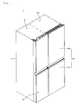
Fig. 1 is a perspective view of a refrigerator according to an embodiment. -
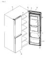
Fig. 2 is a perspective view of the refrigerator with a first door opened according to an embodiment. -
Fig. 3 is a perspective view of the refrigerator with a second door opened according to an embodiment. -
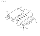
Fig. 4 is an exploded perspective view of an auxiliary shelf according to an embodiment. -
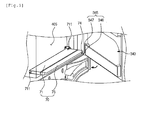
Figs. 5 and6 are views illustrating an operation of the auxiliary shelf according to an opening/closing of the second door. -
Fig. 7 is a view illustrating a state of the auxiliary shelf when the second door is closed. - Hereinafter, exemplary embodiments will be described in detail with reference to the accompanying drawings. The spirit and scope of the present disclosure, however, shall not be construed as being limited to embodiments provided herein. Rather, it will be apparent that other embodiments that fall within the spirit and scope of the present disclosure may easily be derived through adding, modifying, and deleting elements herein.
- For convenience of understanding and description, although a side-by-side type refrigerator is exemplified in the current embodiment, the present disclosure is not limited thereto. For example, the present disclosure may be applied to all types of refrigerators including a door opened or closed by rotation.
-
Fig. 1 is a perspective view of a refrigerator according to an embodiment.Fig. 2 is a perspective view of the refrigerator with a first door opened according to an embodiment.Fig. 3 is a perspective view of the refrigerator with a second door opened according to an embodiment. - Referring to
Figs. 1 to 3 , arefrigerator 1 according to an embodiment may include acabinet 10 defining a storage space anddoors refrigerator 1 may be defined by thecabinet 10 and thedoors - The inside of the
cabinet 10 is partitioned in left and right parts to define afreezing compartment 102 and a refrigeratingcompartment 104, respectively. Also, thedoors freezing compartment door 20 for covering thefreezing compartment 102 and a refrigeratingcompartment door 30 for covering the refrigeratingcompartment 104. - Also, an
accommodation device 40 defining a separate space separated from the inside of the refrigeratingcompartment 104 may be disposed in the refrigeratingcompartment door 30. Thus, when the refrigeratingcompartment door 30 is closed, the inside of the refrigeratingcompartment 104 may be defined as a first storage compartment, and the inside of theaccommodation device 40 may be defined as asecond storage compartment 405. - The refrigerating
compartment door 30 may include afirst door 310 for opening or closing thefirst storage compartment 104 and asecond door 340 for opening or closing thesecond storage compartment 405. - An upper end of the
first door 310 is connected to a top surface of thecabinet 10 by adoor hinge 52. Also, thefirst door 310 may be rotatably coupled to thecabinet 10. Although not shown in detail, a separate hinge (not shown) may be disposed on a lower end of thefirst door 310 so that thefirst door 310 is rotatably mounted. Thus, thefirst door 310 may be rotated to open or close the refrigeratingcompartment 104. That is, thefirst door 310 may be rotated to accommodate foods into the refrigeratingcompartment 104. - Also, an
opening 316 is defined in an upper portion of thefirst door 310. The opening 316 may extend from agrip part 313 up to a position adjacent to the upper end of thefirst door 310. Also, the opening 316 may extend up to positions adjacent to both left and right ends of thefirst door 310. Also, theaccommodation device 40 may be disposed on a back surface of thefirst door 310 corresponding to a rear side of theopening 316. Theaccommodation device 40 has a forwardly opened shape. Thus, an access into theaccommodation device 40 may be enabled through theopening 316. - A
sealer 319 contacting a circumference of a front surface of thecabinet 10 when the first door is closed is disposed on a circumference of the back surface of thefirst door 310. Thesealer 319 may be formed of an electrically deformable material and thus be compressible. Also, a magnet may be disposed within thesealer 319 so that thesealer 319 is closely attached to thecabinet 10. - Also, the
opening 316 through which foods accommodated within theaccommodation device 40 are withdrawable in a state where thefirst door 310 is closed is defined in therefrigerating compartment door 30. Thus, theopening 316 may be opened in a state where thefirst door 310 covers therefrigerating compartment 104 to take the foods in or out of theaccommodation device 40. - The
opening 316 may have a size corresponding to a front surface of theaccommodation device 40. Theopening 316 may be vertically defined over a position of thegrip part 313 of thefirst door 310 and horizontally defined up to a region except for portions of both left and right ends of thefirst door 310. Thus, the home bar according to the current embodiment may have a size and usability surely different from that those of a home bar used in a general refrigerator. - The
grip part 313 is configured to open or close the refrigeratingcompartment door 30. Thegrip part 313 is lengthily disposed in a horizontal direction on a center of the refrigeratingcompartment door 30 corresponding to a boundary between thefirst door 310 and thesecond door 340. Thegrip part 313 may be disposed on a position which can be easily grasped by a user. Also, thegrip part 313 may form a boundary portion of lower ends of theopening 316 and thesecond door 340 to hide an existence of thesecond door 340. - The
grip part 313 may have an inwardly recessed shape. Also, the inside of thegrip part 313 may be a downwardly recessed shape so that the user easily grasps thegrip part 313. Thegrip part 313 may be applied to the freezingcompartment door 20 in the same shape as that of the refrigeratingcompartment door 30. When viewed from a front side, a left end and a right end of thegrip part 313 may have the same height. Thus, although thesecond door 340 is disposed on therefrigerating compartment door 30, when viewed from the front side, the refrigeratingcompartment door 30 and the freezingcompartment door 30 may appear to be uniform. - The
second door 340 is configured to open or close theopening 316. Thesecond door 340 is rotatably mounted on thefirst door 310 by anupper hinge 51. Theupper hinge 51 has a structure in which both ends of theupper hinge 51 are respectively shaft-coupled to a top surface of thefirst door 310 and a top surface of thesecond door 340 so that thesecond door 340 is rotated using the first door as a shaft. - A lower hinge (not shown) is further disposed on a lower end of the
second door 340. The lower hinge is disposed between the lower end of thesecond door 340 and theopening 316 to rotatably support thesecond door 340. Although not shown in detail, the lower hinge has a cam structure or a spring structure. Thus, thesecond door 340 may be more smoothly opened or closed. - Also, the
first door 310 and thesecond door 340 may be independently rotated. Thus, thefirst door 310 and thesecond door 340 may be independently manipulated to selectively open or close therefrigerating compartment 104 and theopening 316. - A front surface of the
second door 340 may be formed of the same material as those of thefirst door 310 and the refrigeratingcompartment door 20 to provide a continuous design or pattern. Also, the front surface of thesecond door 340 may be flush with that of the refrigeratingcompartment door 30 below thesecond door 340 in a state where thesecond door 340 is closed. - Also, the upper end and both left and right ends of the
second door 340 are disposed at the same position as those of the refrigeratingcompartment door 30 in the state where thesecond door 340 is closed. The lower end of thesecond door 340 may extend up to a position corresponding to a region in which thegrip part 313 of the refrigeratingcompartment door 30 is disposed. That is, the lower end of thesecond door 340 may extend up to a position corresponding to a stepped portion of the region in which thegrip part 313 of the freezingcompartment door 20 is disposed. Thus, in the state where thesecond door 340 is closed, thesecond door 340 may be integrated with thefirst door 310. When viewed from the front side, sense of unity may be provided so that connection portions on which thesecond door 340 is disposed are not seen. - Thus, in a state where the
first door 310 and thesecond door 340 are closed, when viewed from the front side, the refrigeratingcompartment door 30 and the freezingcompartment door 20 may be seen in the same shape. A person who had never seen the refrigerator before does not easily recognize thesecond door 340. That is, the person may recognize the first andsecond doors - A
protrusion 342 protruding inward may be disposed on the back surface of thesecond door 340. A portion of the back surface of thesecond door 340 protrudes to form theprotrusion 342. Also, theprotrusion 342 protrudes in a shape corresponding to that of theopening 316. Thus, in the state where thesecond door 340 is closed, theprotrusion 342 is disposed inside theopening 316. Also, theprotrusion 342 may be engaged with theopening 316 to prevent cool air from temporarily leaking. - An
accommodation part 343 for accommodating foods is disposed on theprotrusion 342. Theaccommodation part 343 may be disposed inward, and also, a separate basket may be attached to theaccommodation part 343 to form a pocket shape. - Also, a
gasket 344 is disposed along a circumference of theprotrusion 342. Thegasket 344 may be formed of an elastically deformable material such as rubber or silicon. When thesecond door 340 is closed, thegasket 344 may be closely attached to the front surface of the refrigeratingcompartment door 30. Here, thegasket 344 may be in a pressed state to prevent cool air within theaccommodation device 40 from leaking. - A
second door switch 349 for detecting an opening/closing of thesecond door 340 is disposed on an upper end of the refrigeratingcompartment door 30. Thesecond door switch 349 may be configured to output an alarm signal to the outside when thesecond door 340 is not closed. - Also, a locking unit may be disposed on a side end of the back surface of the
second door 340 away from a rotation shaft of thesecond door 340 and a side end of the refrigeratingcompartment door 30 corresponding to the side end of the back surface of thesecond door 340. The locking unit may maintain a state in which thesecond door 340 is closed. Also, the restraint and release of the locking unit may be selectively switched by a push manipulation to selectively restrain thesecond door 340. - The locking unit may have the same structure as a general push switch. The locking unit may include a locking device mounted on a side of the refrigerating
compartment door 30 and including alatch slot 317 in which alatch hook 341 is inserted and thelatch hook 341 disposed on thesecond door 340. Since the locking unit has a structure which is widely used in a general refrigerator, its detailed description will be omitted. - An
auxiliary shelf 70 may be further disposed on a lower end of theopening 316. Theauxiliary shelf 70 may be rotatably mounted on theopening 316. When thesecond door 340 is closed, theauxiliary shelf 70 may be rotated and folded. Also, when thesecond door 340 is opened, theauxiliary shelf 70 may be rotated and unfolded. Theauxiliary shelf 70 may have a length corresponding to a horizontal width of theopening 316. When theauxiliary shelf 70 is unfolded, theauxiliary shelf 70 may have a width which protrudes forward by a predetermined length from theopening 316 to place foods thereon. - Hereinafter, the auxiliary shelf will be described in detail with reference to the accompanying drawings.
-
Fig. 4 is an exploded perspective view of the auxiliary shelf according to an embodiment.Figs. 5 and6 are views illustrating an operation of the auxiliary shelf according to an opening/closing of the second door.Fig. 7 is a view illustrating a state of the auxiliary shelf when the second door is closed. - Referring to
Figs. 4 to 7 , theauxiliary shelf 70 may include amain plate 71 and asub plate 73. Themain plate 71 may have a length corresponding to a horizontal width of theopening 316. Also, themain plate 71 may have a square plate shape. - A
rotation shaft 711 of themain plate 71 is disposed on each of both left and right surfaces of themain plate 71, respectively. Therotation shaft 711 may be axially moved and supported by anelastic member 712. Thus, therotation shaft 711 may be moved to mount or separate themain plate 71 on/from theopening 316. - A damping
member 713 may be further disposed on each of both sides of themain plate 71 or theopening 316. The dampingmember 713 may be coupled to therotation shaft 711. Alternatively, therotation shaft 711 may constitute a portion of the dampingmember 713. Thus, therotation shaft 711 may be configured to allow theauxiliary shelf 70 to be more smoothly rotated and folded. Also, therotation shaft 711 may restrict the rotation of theauxiliary shelf 70 to prevent theauxiliary shelf 70 from being reversely rotated, i.e., further rotated toward the storage space with respect to a vertical state thereof. - The
sub plate 73 is disposed on a front side of themain plate 71. Thesub plate 73 may have a sized corresponding to a horizontal width of themain plate 71. Also, thesub plate 73 is rotatably connected to themain plate 71 by aconnection member 72. - In more detail, the
main plate 71 and thesub plate 73 are connected to each other by theconnection member 72. Theconnection member 72 may be provided in plurality along a horizontal direction at a predetermined distance. Thus, thesub plate 73 may be rotated in a counterclockwise direction (when viewed inFig. 5 ). Couplingshafts 721 protruding in both left and right directions are disposed on front and rear ends of theconnection member 72. Thecoupling shafts 721 are shaft-coupled to the insides of themain plate 71 and thesub plate 73, respectively. - Also, an
insertion hole 714 is defined in a front end of themain plate 71. A rear end of theconnection member 72 is inserted into theinsertion hole 714. Also, aguide hole 731 having a length greater than that of theconnection member 72 is defined in a rear end of thesub plate 73. Thus, when thesub plate 73 is rotated, thesub plate 73 does not interfere with theconnection member 72. - A plurality of
rollers 732 may be disposed on a bottom surface of thesub plate 73. When thesecond door 340 is closed, therollers 732 contact the back surface of thesecond door 340 to more smoothly rotate theauxiliary shelf 70. - That is, if the
auxiliary shelf 70 is rotated at an angle greater than a preset angle when thesecond door 340 is closed, therollers 732 contact the back surface of thesecond door 340. Here, therollers 732 are disposed at positions contacting thesecond door 340 and rolled along the back surface of thesecond door 340 to rotate theauxiliary shelf 70 in the counterclockwise direction. - The bottom surface of the
sub plate 73 includes ahorizontal part 733 and aninclined part 734. Thehorizontal part 733 is disposed from the rear end of thesub plate 73 up to a predetermined distance. Theinclined part 734 is disposed from a front end of thehorizontal part 733 up to the front end of thesub plate 73. Theinclined part 734 is inclined upward toward a front side. Therollers 732 may be disposed on a boundary between thehorizontal part 733 and theinclined part 734. Thus, when thesecond door 340 is closed, thesecond door 340 and theinclined part 734 may contact each other to allow thesub plate 73 and theauxiliary shelf 70 to be easily rotated. - A
guide roller 732 may be disposed on the front end of thesub plate 73 adjacent to therotation shaft 711 of thesecond door 340. Theguide roller 74 may be disposed on a right side of the front end of thesub plate 73. - A
shelf guide 345 is disposed on the back surface of thesecond door 340 corresponding to theguide roller 74 when thesecond door 340 is closed. Theshelf guide 345 may contact theauxiliary shelf 70 to allow theauxiliary shelf 70 to be rotated and folded when thesecond door 340 is closed. - In detail, the
shelf guide 345 protrudes inclinedly from a lower portion of the back surface of thesecond door 340. Theshelf guide 345 may include a firstinclined part 346 contacting theauxiliary shelf 70 and a secondinclined part 347 for further rotating theauxiliary shelf 70. The firstinclined part 346 further protrudes downward from the front end of thesub plate 73 to inclinedly extend upward. The firstinclined part 346 may further protrude from the secondinclined part 347 and be lowered gradually toward the secondinclined part 347. - Also, the second
inclined part 347 extends upward from an upper end of the firstinclined part 346. Also, the secondinclined part 347 may have an inclination less than that of the firstinclined part 346. When thesecond door 340 is closed, the secondinclined part 347 may contact theauxiliary shelf 70 until theauxiliary shelf 70 is completely vertically disposed. - Hereinafter, an operation of the auxiliary shelf will be described.
- When the
second door 340 is closed, as shown inFig. 7 , theauxiliary shelf 70 is closely attached to the back surface of thesecond door 340 in a state where theauxiliary shelf 70 is folded. Here, theauxiliary shelf 70 is vertically folded. Also, theauxiliary shelf 70 is not rotated in the state where theauxiliary shelf 70 contacts thesecond door 340 even though thefirst door 310 is rotated. - When the
second door 340 is closed, the user releases the restraint of thelatch hook 341 to open thesecond door 340. When the restraint of thelatch hook 341 is released, thesecond door 340 is rotated using theupper hinge 51 and the lower hinge as shafts. - Also, when the
second door 340 is rotated, theauxiliary shelf 70 is rotated by a self-weight in a clockwise direction (when viewed inFig. 5 ). When thesecond door 340 is fully opened, as shown inFig. 5 , theauxiliary shelf 70 is fully unfolded. - Here, the
auxiliary shelf 70 is rotated around therotation shaft 711. Therotation shaft 711 is disposed at a rear side somewhat than a center of theauxiliary shelf 70. Thus, theauxiliary shelf 70 may be rotated and unfolded by the self-weight. As necessary, theauxiliary shelf 70 may be automatically rotated and unfolded by a spring or damp. Also, theauxiliary shelf 70 may be rotated and unfolded by user's manipulation without using a separate component. - When the
second door 340 is fully opened, and theauxiliary shelf 70 is fully unfolded, the user may withdraw foods accommodated in the storage space within theopening 316 and place beverages or cups on theauxiliary shelf 70. - When the foods are completely withdrawn through the
opening 316, thesecond door 340 is closed. When thesecond door 340 is closed at an angel greater than a preset angle to further rotate thesecond door 340 as shown inFig. 5 , the firstinclined part 346 contacts theguide roller 74. Here, the most protruding portion of the firstinclined part 346 is disposed under theguide roller 74, and theguide roller 74 contacts an inclined surface of the firstinclined part 346. - In this state, when the
second door 340 is further rotated and thus closed, theguide roller 74 is moved along the inclined surface of the firstinclined part 346. Then, thesub plate 73 may be smoothly rotated in a counterclockwise direction using theconnection member 72 as a shaft. - In this state, when the
second door 340 is further closed, thesub plate 73 is further rotated. Thus, as shown inFig. 6 , theguide roller 74 passes through the firstinclined part 346 to contact the inclined surface of the secondinclined part 347. - When the
guide roller 74 passes through the secondinclined part 347, thesub plate 73 is not further rotated by interfering with theconnection member 72. Thus, in this position, themain plate 71 is rotated around therotation shaft 711 in the counterclockwise direction, and thus, the wholeauxiliary shelf 70 is rotated. In this state, when thesecond door 340 is further rotated, theauxiliary shelf 70 is further rotated. Here, theroller 732 contacts the back surface of thesecond door 340 to allow theauxiliary shelf 70 to be more smoothly rotated. - When the
second door 340 is fully closed, as shown inFig. 7 , theauxiliary shelf 70 is fully unfolded. Thus, theauxiliary shelf 70 vertically stands up in the state where theauxiliary shelf 70 contacts the back surface of thesecond door 340. - According to the proposed embodiment, the auxiliary shelf may be unfolded by being linked with the open of the second door. Thus, the user may place foods to be accommodated in the accommodation device on the unfolded auxiliary shelf to easily realize the accommodation of the foods.
- Also, the auxiliary shelf may be constituted by the main plate and the sub plate. Thus, the auxiliary shelf may be more smoothly folded or unfolded by being linked with the opening/closing of the second door through the contact of the guide roller and the shelf guide, thereby more improving the convenience of use.
- Although embodiments have been described with reference to a number of illustrative embodiments thereof, it should be understood that numerous other modifications and embodiments can be devised by those skilled in the art that will fall within the spirit and scope of the principles of this disclosure. More particularly, various variations and modifications are possible in the component parts and/or arrangements of the subject combination arrangement within the scope of the disclosure, the drawings and the appended claims. In addition to variations and modifications in the component parts and/or arrangements, alternative uses will also be apparent to those skilled in the art.
Claims (15)
- A refrigerator (1) comprising a cabinet (10) defining a storage space (104), a first door (310) rotatably mounted on the cabinet (10), the first door (310) opening or closing the storage space (104), and an opening (316) passing through the first door (310), characterized in that the refrigerator comprises a second door (340) mounted rotatable in the same direction as the first door (310), the second door (340) opening or closing the opening (316) and an auxiliary shelf (70) of which both sides are shaft-coupled to the opening (316), the auxiliary shelf (70) contacting a back surface of the second door (340) and being folded or unfolded in a direction crossing the rotation direction of the second door (340) when the second door (340) is opened.
- The refrigerator according to claim 1, characterized in that the auxiliary shelf (70) comprises:a main plate (71) rotatably mounted on the opening (316);a sub plate (73) disposed on a front side of the main plate (71) to selectively contact the back surface of the second door (340); anda connection member (72) connecting the main plate (71) to the sub plate (73) to allow the sub plate (73) to be rotated in the same direction as the auxiliary shelf (70).
- The refrigerator according to claim 2, characterized in that a bottom surface of the sub plate (73) comprises:a horizontal part (733) extending horizontally from a rear end of the sub plate (73); andan inclined part (734) inclinedly extending upward from a front end of the horizontal part (733) to contact the second door (340) when the auxiliary shelf (70) is initially rotated.
- The refrigerator according to claim 1, characterized in that a roller (732) contacting the back surface of the second door (340) when the second door (340) is closed to allow the auxiliary shelf (70) to be smoothly rotated is further disposed on a bottom surface of the auxiliary shelf (70).
- The refrigerator according to claim 4, characterized in that the roller (732) is provided in plurality in a horizontal direction at a predetermined distance.
- The refrigerator according to claim 2, characterized in that a shelf guide (345) protruding to contact the auxiliary shelf (70) and having an inclined surface for guiding the rotation of the auxiliary shelf (70) is further disposed on the back surface of the second door (340).
- The refrigerator according to claim 6, characterized in that the shelf guide (345) comprises:a first inclined part (346) protruding from the back surface of the second door (340) corresponding to the auxiliary shelf (70), the first inclined part (346) having an inclined surface inclinedly extending upward; anda second inclined part (347) extending upward from an upper end of the first inclined part (346), the second inclined part (347) having an inclination less than that of the first inclined part (346).
- The refrigerator according to claim 7, characterized in that a protruding end of the first inclined part (346) is disposed below a front end of the auxiliary shelf (70).
- The refrigerator according to claim 6, characterized in that a guide roller (74) contacting the shelf guide (345) when the second door (340) is opened or close is further disposed on a front end of the sub plate (73) corresponding to the shelf guide (345).
- The refrigerator according to claim 9, characterized in that the guide roller (74) contacts the first inclined part (346) in a state where the auxiliary shelf (70) is unfolded.
- The refrigerator according to claim 2, characterized a guide hole (731) through which the connection member (72) passes is defined in the sub plate (73), and
the guide hole (731) has a vertical length greater than that of the connection member (72) to allow the sub plate (73) to be independently rotated with respect to the main plate (71). - The refrigerator according to claim 2, characterized in that front end rear ends of the connection member (72) are rotatably connected to the main plate (71) and the sub plate (73), respectively.
- The refrigerator according to claim 2, characterized in that the connection member (72) is inserted into the main plate (71) and the sub plate (73), and
the main plate (71) and the sub plate (73) are maintained in contact with each other. - The refrigerator according to claim 1, characterized in that an accommodation device (405) defining an accommodation space accessible through the opening (316) is disposed in a back surface of the first door (310).
- The refrigerator according to claim 1, characterized in that a damping member (713) connected to a rotation shaft (711) of the main plate (71) to allow the auxiliary shelf (70) to be smoothly unfolded is further disposed on a side of the main plate (71) or the opening (316).
Priority Applications (1)
| Application Number | Priority Date | Filing Date | Title |
|---|---|---|---|
| EP20157591.7A EP3674640B1 (en) | 2011-11-11 | 2012-11-02 | Refrigerator |
Applications Claiming Priority (1)
| Application Number | Priority Date | Filing Date | Title |
|---|---|---|---|
| KR1020110117326A KR101844072B1 (en) | 2011-11-11 | 2011-11-11 | Refirgerator |
Related Child Applications (2)
| Application Number | Title | Priority Date | Filing Date |
|---|---|---|---|
| EP20157591.7A Division-Into EP3674640B1 (en) | 2011-11-11 | 2012-11-02 | Refrigerator |
| EP20157591.7A Division EP3674640B1 (en) | 2011-11-11 | 2012-11-02 | Refrigerator |
Publications (3)
| Publication Number | Publication Date |
|---|---|
| EP2594879A2 true EP2594879A2 (en) | 2013-05-22 |
| EP2594879A3 EP2594879A3 (en) | 2014-06-04 |
| EP2594879B1 EP2594879B1 (en) | 2020-04-01 |
Family
ID=47221068
Family Applications (2)
| Application Number | Title | Priority Date | Filing Date |
|---|---|---|---|
| EP20157591.7A Active EP3674640B1 (en) | 2011-11-11 | 2012-11-02 | Refrigerator |
| EP12007486.9A Active EP2594879B1 (en) | 2011-11-11 | 2012-11-02 | Refrigerator |
Family Applications Before (1)
| Application Number | Title | Priority Date | Filing Date |
|---|---|---|---|
| EP20157591.7A Active EP3674640B1 (en) | 2011-11-11 | 2012-11-02 | Refrigerator |
Country Status (3)
| Country | Link |
|---|---|
| US (1) | US8851589B2 (en) |
| EP (2) | EP3674640B1 (en) |
| KR (1) | KR101844072B1 (en) |
Cited By (2)
| Publication number | Priority date | Publication date | Assignee | Title |
|---|---|---|---|---|
| EP3070421A1 (en) * | 2015-03-18 | 2016-09-21 | LG Electronics Inc. | Refrigerator |
| CN106679305A (en) * | 2017-01-05 | 2017-05-17 | 合肥华凌股份有限公司 | Rotating type bottle holder structure and refrigerator |
Families Citing this family (12)
| Publication number | Priority date | Publication date | Assignee | Title |
|---|---|---|---|---|
| KR101918296B1 (en) * | 2012-06-21 | 2019-01-29 | 엘지전자 주식회사 | Refirgerator |
| KR102208532B1 (en) * | 2013-12-23 | 2021-01-28 | 엘지전자 주식회사 | Refirgerator |
| KR102234011B1 (en) * | 2014-02-17 | 2021-03-29 | 엘지전자 주식회사 | Refrigerator |
| KR101691260B1 (en) * | 2014-10-17 | 2016-12-29 | 엘지전자 주식회사 | Refrigerator |
| KR101653315B1 (en) * | 2015-03-18 | 2016-09-01 | 엘지전자 주식회사 | Refrigerator |
| KR102098689B1 (en) * | 2015-07-08 | 2020-04-08 | 삼성전자주식회사 | Refrigerator |
| KR102577442B1 (en) * | 2016-06-07 | 2023-09-11 | 엘지전자 주식회사 | Refrigerator and folding guide device therein |
| CN106014120A (en) * | 2016-07-07 | 2016-10-12 | 黄为 | Elastic rainwater utilization greening unit |
| KR102573779B1 (en) | 2018-11-20 | 2023-09-04 | 삼성전자주식회사 | Refrigerator |
| KR20210032812A (en) * | 2019-09-17 | 2021-03-25 | 엘지전자 주식회사 | Refrigerator |
| US11668513B2 (en) | 2020-12-01 | 2023-06-06 | Electrolux Home Products, Inc. | Staged access door for a home appliance |
| US11215391B1 (en) * | 2020-12-01 | 2022-01-04 | Electrolux Home Products, Inc. | Staged access door for a home appliance |
Citations (2)
| Publication number | Priority date | Publication date | Assignee | Title |
|---|---|---|---|---|
| KR19990031102A (en) | 1997-10-08 | 1999-05-06 | 윤종용 | Master Disc Manufacturing Method for Optical Disc Production |
| KR20090020024A (en) | 2007-08-22 | 2009-02-26 | 엘지전자 주식회사 | Refrigerator |
Family Cites Families (30)
| Publication number | Priority date | Publication date | Assignee | Title |
|---|---|---|---|---|
| US1350503A (en) * | 1920-04-12 | 1920-08-24 | Irvine Benjamin | Leaf-supporting mechanism |
| US1670959A (en) * | 1926-10-21 | 1928-05-22 | Garrett Stuart Grayson | Attachment for household refrigerators |
| US2112771A (en) * | 1934-03-30 | 1938-03-29 | Nash Kelvinator Corp | Refrigerating apparatus |
| US2095811A (en) * | 1934-03-30 | 1937-10-12 | Kelvinator Corp | Refrigerating apparatus |
| US2122501A (en) * | 1934-07-28 | 1938-07-05 | Nash Kelvinator Corp | Refrigerating apparatus |
| US2118735A (en) * | 1935-01-15 | 1938-05-24 | Crosley Radio Corp | Refrigerator |
| US2124857A (en) * | 1935-02-15 | 1938-07-26 | Harold F Macgrath | Refrigerator |
| US2381598A (en) * | 1944-03-18 | 1945-08-07 | Philco Corp | Refrigerator cabinet construction |
| US3045746A (en) * | 1958-03-25 | 1962-07-24 | Mac Gregor Comarain Sa | Method and means for mounting and operating hingedly interconnected panel elements for closing hatchways, railway cars and like open spaces |
| JPS5226303Y2 (en) * | 1973-10-02 | 1977-06-15 | ||
| US4087140A (en) * | 1977-04-14 | 1978-05-02 | Whirlpool Corporation | Magnetic latch - movable ice receptacle |
| KR0122137Y1 (en) * | 1993-09-21 | 1998-10-01 | 김광호 | The open and close apparatus of a washing machine's door |
| KR0130587Y1 (en) * | 1995-11-09 | 1998-12-15 | 김광호 | Door of a washing machine |
| US5860717A (en) * | 1996-02-01 | 1999-01-19 | Mizrahi; Shalom | Drawer stop device |
| US6401478B2 (en) * | 2000-04-19 | 2002-06-11 | Whirlpool Corporation | Ice maker with cooperating inner and outer doors |
| US6484529B2 (en) * | 2000-04-19 | 2002-11-26 | Whirlpool Corporation | Cabinet construction for an ice maker or other refrigeration appliance |
| US6779858B2 (en) * | 2002-02-13 | 2004-08-24 | Shalom Mizrahi | Drawer stop device with dual-side mountable roller |
| US7246866B2 (en) * | 2003-04-29 | 2007-07-24 | Shalom Mizrahi | Drawer stop device with dual-side mountable roller |
| KR101024464B1 (en) * | 2003-12-31 | 2011-03-23 | 엘지전자 주식회사 | Home bar of refrigerator |
| KR101036306B1 (en) * | 2004-08-13 | 2011-05-23 | 엘지전자 주식회사 | Home bar structure for refrigerator |
| CN100549591C (en) * | 2005-06-30 | 2009-10-14 | 乐金电子(天津)电器有限公司 | The structure of use in refrigerator family bar |
| KR200459216Y1 (en) * | 2007-08-21 | 2012-03-22 | 삼성전자주식회사 | Refrigerator |
| US8182055B2 (en) * | 2008-04-22 | 2012-05-22 | Samsung Electronics Co., Ltd. | Damping unit and refrigerator having the same |
| EP2159522A1 (en) * | 2008-08-27 | 2010-03-03 | Panasonic Corporation | Refrigerator |
| KR20100122155A (en) * | 2009-05-12 | 2010-11-22 | 엘지전자 주식회사 | Refrigerator |
| KR101307681B1 (en) * | 2009-06-03 | 2013-09-12 | 엘지전자 주식회사 | Refrigerator |
| KR20110017680A (en) * | 2009-08-14 | 2011-02-22 | 엘지전자 주식회사 | Refrigerator |
| CN102116554A (en) | 2010-01-04 | 2011-07-06 | Lg电子株式会社 | Refrigerator |
| KR101923471B1 (en) * | 2011-10-04 | 2018-11-29 | 엘지전자 주식회사 | Refrigerator |
| KR101918296B1 (en) * | 2012-06-21 | 2019-01-29 | 엘지전자 주식회사 | Refirgerator |
-
2011
- 2011-11-11 KR KR1020110117326A patent/KR101844072B1/en active IP Right Grant
-
2012
- 2012-11-02 EP EP20157591.7A patent/EP3674640B1/en active Active
- 2012-11-02 EP EP12007486.9A patent/EP2594879B1/en active Active
- 2012-11-07 US US13/670,996 patent/US8851589B2/en active Active
Patent Citations (2)
| Publication number | Priority date | Publication date | Assignee | Title |
|---|---|---|---|---|
| KR19990031102A (en) | 1997-10-08 | 1999-05-06 | 윤종용 | Master Disc Manufacturing Method for Optical Disc Production |
| KR20090020024A (en) | 2007-08-22 | 2009-02-26 | 엘지전자 주식회사 | Refrigerator |
Cited By (6)
| Publication number | Priority date | Publication date | Assignee | Title |
|---|---|---|---|---|
| EP3070421A1 (en) * | 2015-03-18 | 2016-09-21 | LG Electronics Inc. | Refrigerator |
| CN105987559A (en) * | 2015-03-18 | 2016-10-05 | Lg电子株式会社 | Refrigerator |
| US9879901B2 (en) | 2015-03-18 | 2018-01-30 | Lg Electronics Inc. | Refrigerator |
| CN105987559B (en) * | 2015-03-18 | 2018-07-17 | Lg电子株式会社 | Refrigerator |
| EP3543632A1 (en) * | 2015-03-18 | 2019-09-25 | LG Electronics Inc. | Refrigerator |
| CN106679305A (en) * | 2017-01-05 | 2017-05-17 | 合肥华凌股份有限公司 | Rotating type bottle holder structure and refrigerator |
Also Published As
| Publication number | Publication date |
|---|---|
| EP2594879B1 (en) | 2020-04-01 |
| EP3674640B1 (en) | 2022-10-19 |
| EP3674640A1 (en) | 2020-07-01 |
| US8851589B2 (en) | 2014-10-07 |
| US20130119849A1 (en) | 2013-05-16 |
| KR101844072B1 (en) | 2018-05-15 |
| KR20130052092A (en) | 2013-05-22 |
| EP2594879A3 (en) | 2014-06-04 |
Similar Documents
| Publication | Publication Date | Title |
|---|---|---|
| EP2594879B1 (en) | Refrigerator | |
| US9759477B2 (en) | Refrigerator | |
| EP2677258B1 (en) | Refrigerator | |
| US20150115790A1 (en) | Refrigerator | |
| US20130119845A1 (en) | Refrigerator | |
| EP3207319B1 (en) | Refrigerator | |
| KR101923471B1 (en) | Refrigerator | |
| KR101861368B1 (en) | Refrigerator | |
| KR102227959B1 (en) | Refirgerator | |
| EP2431691A1 (en) | Refrigerator | |
| KR20130053593A (en) | Refrigerator | |
| KR101155206B1 (en) | Drawer type home-bar apparatus for a refrigerator | |
| KR102179342B1 (en) | Refirgerator | |
| KR102093435B1 (en) | Refirgerator | |
| KR20140017190A (en) | Door basket for a refrigerator | |
| KR102111717B1 (en) | Refirgerator | |
| KR102093461B1 (en) | Refirgerator | |
| KR102093448B1 (en) | Refirgerator | |
| KR102093456B1 (en) | Refirgerator | |
| KR20200132793A (en) | Refirgerator | |
| KR102208532B1 (en) | Refirgerator | |
| KR20140113070A (en) | Refrigerator | |
| KR20090083653A (en) | Refrigerator | |
| KR20120039907A (en) | A refrigerator |
Legal Events
| Date | Code | Title | Description |
|---|---|---|---|
| PUAI | Public reference made under article 153(3) epc to a published international application that has entered the european phase |
Free format text: ORIGINAL CODE: 0009012 |
|
| AK | Designated contracting states |
Kind code of ref document: A2 Designated state(s): AL AT BE BG CH CY CZ DE DK EE ES FI FR GB GR HR HU IE IS IT LI LT LU LV MC MK MT NL NO PL PT RO RS SE SI SK SM TR |
|
| AX | Request for extension of the european patent |
Extension state: BA ME |
|
| PUAL | Search report despatched |
Free format text: ORIGINAL CODE: 0009013 |
|
| AK | Designated contracting states |
Kind code of ref document: A3 Designated state(s): AL AT BE BG CH CY CZ DE DK EE ES FI FR GB GR HR HU IE IS IT LI LT LU LV MC MK MT NL NO PL PT RO RS SE SI SK SM TR |
|
| AX | Request for extension of the european patent |
Extension state: BA ME |
|
| RIC1 | Information provided on ipc code assigned before grant |
Ipc: F25D 25/02 20060101AFI20140425BHEP Ipc: F25D 23/02 20060101ALI20140425BHEP |
|
| 17P | Request for examination filed |
Effective date: 20141117 |
|
| RBV | Designated contracting states (corrected) |
Designated state(s): AL AT BE BG CH CY CZ DE DK EE ES FI FR GB GR HR HU IE IS IT LI LT LU LV MC MK MT NL NO PL PT RO RS SE SI SK SM TR |
|
| STAA | Information on the status of an ep patent application or granted ep patent |
Free format text: STATUS: EXAMINATION IS IN PROGRESS |
|
| 17Q | First examination report despatched |
Effective date: 20171103 |
|
| GRAP | Despatch of communication of intention to grant a patent |
Free format text: ORIGINAL CODE: EPIDOSNIGR1 |
|
| STAA | Information on the status of an ep patent application or granted ep patent |
Free format text: STATUS: GRANT OF PATENT IS INTENDED |
|
| INTG | Intention to grant announced |
Effective date: 20191016 |
|
| RAP1 | Party data changed (applicant data changed or rights of an application transferred) |
Owner name: LG ELECTRONICS INC. |
|
| GRAS | Grant fee paid |
Free format text: ORIGINAL CODE: EPIDOSNIGR3 |
|
| GRAA | (expected) grant |
Free format text: ORIGINAL CODE: 0009210 |
|
| STAA | Information on the status of an ep patent application or granted ep patent |
Free format text: STATUS: THE PATENT HAS BEEN GRANTED |
|
| AK | Designated contracting states |
Kind code of ref document: B1 Designated state(s): AL AT BE BG CH CY CZ DE DK EE ES FI FR GB GR HR HU IE IS IT LI LT LU LV MC MK MT NL NO PL PT RO RS SE SI SK SM TR |
|
| REG | Reference to a national code |
Ref country code: GB Ref legal event code: FG4D |
|
| REG | Reference to a national code |
Ref country code: CH Ref legal event code: EP Ref country code: AT Ref legal event code: REF Ref document number: 1251879 Country of ref document: AT Kind code of ref document: T Effective date: 20200415 |
|
| REG | Reference to a national code |
Ref country code: DE Ref legal event code: R096 Ref document number: 602012068849 Country of ref document: DE |
|
| REG | Reference to a national code |
Ref country code: IE Ref legal event code: FG4D |
|
| PG25 | Lapsed in a contracting state [announced via postgrant information from national office to epo] |
Ref country code: BG Free format text: LAPSE BECAUSE OF FAILURE TO SUBMIT A TRANSLATION OF THE DESCRIPTION OR TO PAY THE FEE WITHIN THE PRESCRIBED TIME-LIMIT Effective date: 20200701 |
|
| REG | Reference to a national code |
Ref country code: NL Ref legal event code: MP Effective date: 20200401 |
|
| REG | Reference to a national code |
Ref country code: LT Ref legal event code: MG4D |
|
| PG25 | Lapsed in a contracting state [announced via postgrant information from national office to epo] |
Ref country code: GR Free format text: LAPSE BECAUSE OF FAILURE TO SUBMIT A TRANSLATION OF THE DESCRIPTION OR TO PAY THE FEE WITHIN THE PRESCRIBED TIME-LIMIT Effective date: 20200702 Ref country code: FI Free format text: LAPSE BECAUSE OF FAILURE TO SUBMIT A TRANSLATION OF THE DESCRIPTION OR TO PAY THE FEE WITHIN THE PRESCRIBED TIME-LIMIT Effective date: 20200401 Ref country code: NO Free format text: LAPSE BECAUSE OF FAILURE TO SUBMIT A TRANSLATION OF THE DESCRIPTION OR TO PAY THE FEE WITHIN THE PRESCRIBED TIME-LIMIT Effective date: 20200701 Ref country code: LT Free format text: LAPSE BECAUSE OF FAILURE TO SUBMIT A TRANSLATION OF THE DESCRIPTION OR TO PAY THE FEE WITHIN THE PRESCRIBED TIME-LIMIT Effective date: 20200401 Ref country code: PT Free format text: LAPSE BECAUSE OF FAILURE TO SUBMIT A TRANSLATION OF THE DESCRIPTION OR TO PAY THE FEE WITHIN THE PRESCRIBED TIME-LIMIT Effective date: 20200817 Ref country code: IS Free format text: LAPSE BECAUSE OF FAILURE TO SUBMIT A TRANSLATION OF THE DESCRIPTION OR TO PAY THE FEE WITHIN THE PRESCRIBED TIME-LIMIT Effective date: 20200801 Ref country code: SE Free format text: LAPSE BECAUSE OF FAILURE TO SUBMIT A TRANSLATION OF THE DESCRIPTION OR TO PAY THE FEE WITHIN THE PRESCRIBED TIME-LIMIT Effective date: 20200401 Ref country code: CZ Free format text: LAPSE BECAUSE OF FAILURE TO SUBMIT A TRANSLATION OF THE DESCRIPTION OR TO PAY THE FEE WITHIN THE PRESCRIBED TIME-LIMIT Effective date: 20200401 Ref country code: NL Free format text: LAPSE BECAUSE OF FAILURE TO SUBMIT A TRANSLATION OF THE DESCRIPTION OR TO PAY THE FEE WITHIN THE PRESCRIBED TIME-LIMIT Effective date: 20200401 |
|
| REG | Reference to a national code |
Ref country code: AT Ref legal event code: MK05 Ref document number: 1251879 Country of ref document: AT Kind code of ref document: T Effective date: 20200401 |
|
| PG25 | Lapsed in a contracting state [announced via postgrant information from national office to epo] |
Ref country code: RS Free format text: LAPSE BECAUSE OF FAILURE TO SUBMIT A TRANSLATION OF THE DESCRIPTION OR TO PAY THE FEE WITHIN THE PRESCRIBED TIME-LIMIT Effective date: 20200401 Ref country code: LV Free format text: LAPSE BECAUSE OF FAILURE TO SUBMIT A TRANSLATION OF THE DESCRIPTION OR TO PAY THE FEE WITHIN THE PRESCRIBED TIME-LIMIT Effective date: 20200401 Ref country code: HR Free format text: LAPSE BECAUSE OF FAILURE TO SUBMIT A TRANSLATION OF THE DESCRIPTION OR TO PAY THE FEE WITHIN THE PRESCRIBED TIME-LIMIT Effective date: 20200401 |
|
| PG25 | Lapsed in a contracting state [announced via postgrant information from national office to epo] |
Ref country code: AL Free format text: LAPSE BECAUSE OF FAILURE TO SUBMIT A TRANSLATION OF THE DESCRIPTION OR TO PAY THE FEE WITHIN THE PRESCRIBED TIME-LIMIT Effective date: 20200401 |
|
| REG | Reference to a national code |
Ref country code: DE Ref legal event code: R097 Ref document number: 602012068849 Country of ref document: DE |
|
| PG25 | Lapsed in a contracting state [announced via postgrant information from national office to epo] |
Ref country code: ES Free format text: LAPSE BECAUSE OF FAILURE TO SUBMIT A TRANSLATION OF THE DESCRIPTION OR TO PAY THE FEE WITHIN THE PRESCRIBED TIME-LIMIT Effective date: 20200401 Ref country code: DK Free format text: LAPSE BECAUSE OF FAILURE TO SUBMIT A TRANSLATION OF THE DESCRIPTION OR TO PAY THE FEE WITHIN THE PRESCRIBED TIME-LIMIT Effective date: 20200401 Ref country code: AT Free format text: LAPSE BECAUSE OF FAILURE TO SUBMIT A TRANSLATION OF THE DESCRIPTION OR TO PAY THE FEE WITHIN THE PRESCRIBED TIME-LIMIT Effective date: 20200401 Ref country code: IT Free format text: LAPSE BECAUSE OF FAILURE TO SUBMIT A TRANSLATION OF THE DESCRIPTION OR TO PAY THE FEE WITHIN THE PRESCRIBED TIME-LIMIT Effective date: 20200401 Ref country code: RO Free format text: LAPSE BECAUSE OF FAILURE TO SUBMIT A TRANSLATION OF THE DESCRIPTION OR TO PAY THE FEE WITHIN THE PRESCRIBED TIME-LIMIT Effective date: 20200401 Ref country code: EE Free format text: LAPSE BECAUSE OF FAILURE TO SUBMIT A TRANSLATION OF THE DESCRIPTION OR TO PAY THE FEE WITHIN THE PRESCRIBED TIME-LIMIT Effective date: 20200401 Ref country code: SM Free format text: LAPSE BECAUSE OF FAILURE TO SUBMIT A TRANSLATION OF THE DESCRIPTION OR TO PAY THE FEE WITHIN THE PRESCRIBED TIME-LIMIT Effective date: 20200401 |
|
| PLBE | No opposition filed within time limit |
Free format text: ORIGINAL CODE: 0009261 |
|
| STAA | Information on the status of an ep patent application or granted ep patent |
Free format text: STATUS: NO OPPOSITION FILED WITHIN TIME LIMIT |
|
| PG25 | Lapsed in a contracting state [announced via postgrant information from national office to epo] |
Ref country code: PL Free format text: LAPSE BECAUSE OF FAILURE TO SUBMIT A TRANSLATION OF THE DESCRIPTION OR TO PAY THE FEE WITHIN THE PRESCRIBED TIME-LIMIT Effective date: 20200401 Ref country code: SK Free format text: LAPSE BECAUSE OF FAILURE TO SUBMIT A TRANSLATION OF THE DESCRIPTION OR TO PAY THE FEE WITHIN THE PRESCRIBED TIME-LIMIT Effective date: 20200401 |
|
| 26N | No opposition filed |
Effective date: 20210112 |
|
| PG25 | Lapsed in a contracting state [announced via postgrant information from national office to epo] |
Ref country code: SI Free format text: LAPSE BECAUSE OF FAILURE TO SUBMIT A TRANSLATION OF THE DESCRIPTION OR TO PAY THE FEE WITHIN THE PRESCRIBED TIME-LIMIT Effective date: 20200401 |
|
| PG25 | Lapsed in a contracting state [announced via postgrant information from national office to epo] |
Ref country code: MC Free format text: LAPSE BECAUSE OF FAILURE TO SUBMIT A TRANSLATION OF THE DESCRIPTION OR TO PAY THE FEE WITHIN THE PRESCRIBED TIME-LIMIT Effective date: 20200401 |
|
| REG | Reference to a national code |
Ref country code: CH Ref legal event code: PL |
|
| PG25 | Lapsed in a contracting state [announced via postgrant information from national office to epo] |
Ref country code: LU Free format text: LAPSE BECAUSE OF NON-PAYMENT OF DUE FEES Effective date: 20201102 |
|
| REG | Reference to a national code |
Ref country code: BE Ref legal event code: MM Effective date: 20201130 |
|
| PG25 | Lapsed in a contracting state [announced via postgrant information from national office to epo] |
Ref country code: CH Free format text: LAPSE BECAUSE OF NON-PAYMENT OF DUE FEES Effective date: 20201130 Ref country code: LI Free format text: LAPSE BECAUSE OF NON-PAYMENT OF DUE FEES Effective date: 20201130 |
|
| PG25 | Lapsed in a contracting state [announced via postgrant information from national office to epo] |
Ref country code: IE Free format text: LAPSE BECAUSE OF NON-PAYMENT OF DUE FEES Effective date: 20201102 |
|
| PG25 | Lapsed in a contracting state [announced via postgrant information from national office to epo] |
Ref country code: TR Free format text: LAPSE BECAUSE OF FAILURE TO SUBMIT A TRANSLATION OF THE DESCRIPTION OR TO PAY THE FEE WITHIN THE PRESCRIBED TIME-LIMIT Effective date: 20200401 Ref country code: MT Free format text: LAPSE BECAUSE OF FAILURE TO SUBMIT A TRANSLATION OF THE DESCRIPTION OR TO PAY THE FEE WITHIN THE PRESCRIBED TIME-LIMIT Effective date: 20200401 Ref country code: CY Free format text: LAPSE BECAUSE OF FAILURE TO SUBMIT A TRANSLATION OF THE DESCRIPTION OR TO PAY THE FEE WITHIN THE PRESCRIBED TIME-LIMIT Effective date: 20200401 |
|
| PG25 | Lapsed in a contracting state [announced via postgrant information from national office to epo] |
Ref country code: MK Free format text: LAPSE BECAUSE OF FAILURE TO SUBMIT A TRANSLATION OF THE DESCRIPTION OR TO PAY THE FEE WITHIN THE PRESCRIBED TIME-LIMIT Effective date: 20200401 |
|
| PG25 | Lapsed in a contracting state [announced via postgrant information from national office to epo] |
Ref country code: BE Free format text: LAPSE BECAUSE OF NON-PAYMENT OF DUE FEES Effective date: 20201130 |
|
| PGFP | Annual fee paid to national office [announced via postgrant information from national office to epo] |
Ref country code: GB Payment date: 20231006 Year of fee payment: 12 |
|
| PGFP | Annual fee paid to national office [announced via postgrant information from national office to epo] |
Ref country code: FR Payment date: 20231006 Year of fee payment: 12 Ref country code: DE Payment date: 20231005 Year of fee payment: 12 |