EP2594878A2 - Refrigerator - Google Patents
Refrigerator Download PDFInfo
- Publication number
- EP2594878A2 EP2594878A2 EP12007425.7A EP12007425A EP2594878A2 EP 2594878 A2 EP2594878 A2 EP 2594878A2 EP 12007425 A EP12007425 A EP 12007425A EP 2594878 A2 EP2594878 A2 EP 2594878A2
- Authority
- EP
- European Patent Office
- Prior art keywords
- refrigerator
- drawer
- rail
- compartment
- roller
- Prior art date
- Legal status (The legal status is an assumption and is not a legal conclusion. Google has not performed a legal analysis and makes no representation as to the accuracy of the status listed.)
- Granted
Links
Images


Classifications
-
- F—MECHANICAL ENGINEERING; LIGHTING; HEATING; WEAPONS; BLASTING
- F25—REFRIGERATION OR COOLING; COMBINED HEATING AND REFRIGERATION SYSTEMS; HEAT PUMP SYSTEMS; MANUFACTURE OR STORAGE OF ICE; LIQUEFACTION SOLIDIFICATION OF GASES
- F25D—REFRIGERATORS; COLD ROOMS; ICE-BOXES; COOLING OR FREEZING APPARATUS NOT OTHERWISE PROVIDED FOR
- F25D25/00—Charging, supporting, and discharging the articles to be cooled
-
- F—MECHANICAL ENGINEERING; LIGHTING; HEATING; WEAPONS; BLASTING
- F25—REFRIGERATION OR COOLING; COMBINED HEATING AND REFRIGERATION SYSTEMS; HEAT PUMP SYSTEMS; MANUFACTURE OR STORAGE OF ICE; LIQUEFACTION SOLIDIFICATION OF GASES
- F25D—REFRIGERATORS; COLD ROOMS; ICE-BOXES; COOLING OR FREEZING APPARATUS NOT OTHERWISE PROVIDED FOR
- F25D23/00—General constructional features
-
- F—MECHANICAL ENGINEERING; LIGHTING; HEATING; WEAPONS; BLASTING
- F25—REFRIGERATION OR COOLING; COMBINED HEATING AND REFRIGERATION SYSTEMS; HEAT PUMP SYSTEMS; MANUFACTURE OR STORAGE OF ICE; LIQUEFACTION SOLIDIFICATION OF GASES
- F25D—REFRIGERATORS; COLD ROOMS; ICE-BOXES; COOLING OR FREEZING APPARATUS NOT OTHERWISE PROVIDED FOR
- F25D25/00—Charging, supporting, and discharging the articles to be cooled
- F25D25/02—Charging, supporting, and discharging the articles to be cooled by shelves
- F25D25/024—Slidable shelves
- F25D25/025—Drawers
Definitions
- This relates to a refrigerator, and more particularly, to a refrigerator efficiently using the space of a refrigerating compartment and/or freezing compartment.
- a refrigerator stores items in a frozen or refrigerated state by lowering an internal temperature of a compartment thereof through discharge of cold air generated by a refrigeration cycle including a compressor, a condenser, an expansion valve, and an evaporator.
- a refrigerator may include a freezing compartment for storing items in a frozen state, and a refrigerating compartment for storing items at low temperature.
- a Kimchi refrigerator may store items such as Kimchi or vegetables in a fresh state.
- a refrigerator may include a plurality of doors, at least one of the plurality of doors being connected to a refrigerator body by hinges to open or close a front side of the refrigerator body.
- the refrigerator may include a drawer type door mounted to a front wall of a drawer slidably installed in the refrigerator. Items of various sizes and shapes may be stored in the freezing and refrigerating compartments, which may include a plurality of shelves or racks to vertically partition the storage compartment to receive such items.
- the drawer described above may include mounting structures at opposite lateral sides thereof which may reduce storage space of the drawer.
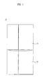
- FIG. 1 is a front view of an exemplary refrigerator according to an embodiment as broadly described herein;
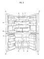
- FIG. 2 is a front view of the refrigerator shown in FIG. 1 with its doors open;
- FIG. 3 is a perspective view of a drawer of the refrigerator, according to an embodiment as broadly described herein;
- FIG. 4 is a side view of the drawer shown in FIG. 3 ;
- FIG. 5 is an exploded perspective view of the drawer shown in FIG. 3 ;
- FIG. 6 is a detail view of a coupled state of first and second rails of the drawer shown in FIGs. 3-5 ;
- FIGs. 7 and 8 illustrate moved states of the drawer shown in FIGs. 3-6 .
- the refrigerator which is designated by reference numeral "10" is applicable not only to a top mount type refrigerator in which the inner space of the refrigerator is vertically partitioned to define a freezing compartment and a refrigerating compartment such that the freezing compartment is arranged above the refrigerating compartment, but also to a side-by-side type refrigerator in which the inner space of the refrigerator is laterally partitioned to define a freezing compartment and a refrigerating compartment such that the freezing compartment and refrigerating compartment are laterally arranged.
- exemplary embodiments will be described in conjunction with a bottom freezer type refrigerator. That is, the inner space of the exemplary refrigerator 10 is vertically partitioned to define a freezing compartment 32 positioned below a refrigerating compartment 22.
- the freezing compartment 32 may be maintained at a sub-zero temperature, and the refrigerating compartment 22 may be maintained at a temperature relatively higher than that of the freezing compartment 32.
- the refrigerator 10 may include a body which defines an outer appearance of the refrigerator 10 while also protecting mechanical devices received therein.
- the body of the refrigerator 10 may include an outer case 12 which defines an outer appearance of the refrigerator 10, and an inner case 14 which defines storage compartments therein, namely, the freezing compartment 32 and the refrigerating compartment 22.
- a certain space may be defined between the outer case 12 and the inner case 14.
- a passage for circulation of cold air may be formed in the space.
- a machinery chamber may be formed in the space between the outer case 12 and the inner case 14 to accommodate a refrigerant cycle device for generating cold air through circulation of a refrigerant.
- a refrigerant cycle device for generating cold air through circulation of a refrigerant.
- the refrigerant cycle device may include, for example, a compressor for compressing a refrigerant, and an evaporator for changing the phase of the refrigerant from liquid to gas, to cause the refrigerant to exchange heat with the outside of the refrigerant cycle device.
- the refrigerator 10 may include a freezing compartment door 30 for opening or closing the freezing compartment 32, and a refrigerating compartment door 20 for opening or closing the refrigerating compartment 22.
- Each of the freezing compartment door 30 and refrigerating compartment door 20 may be pivotally mounted to the body of the refrigerator 10 at one end thereof by hinges.
- Each of the freezing compartment door 30 and refrigerating compartment door 20 may include a plurality of doors. That is, as shown in FIG. 2 , each of the freezing compartment door 30 and refrigerating compartment door 20 may be configured such that it opens forward while being pivotally moved about opposite lateral edges of the refrigerator 10.
- a barrier 16 may be positioned between the freezing compartment 32 and the refrigerating compartment 22, to partition the freezing compartment 32 and refrigerating compartment 22.
- the barrier 16 may be formed at the inner case 14 such that it has a certain thickness.
- the barrier 16 may extend horizontally to vertically partition the freezing compartment 32 and refrigerating compartment 22 such that the freezing compartment 32 and refrigerating compartment 22 are disposed below and above the barrier 16, respectively.
- a partition wall 18 may be positioned in the freezing compartment 32, for example, at a central portion thereof, to partition the freezing compartment 32 into two separate spaces.
- the partition wall 18 may be vertically installed at the inner case 14 such that the freezing compartment 32 is divided into two laterally arranged compartments.
- the freezing compartment door 30 may include two doors for opening or closing respective freezing compartments 32.
- FIGs. 1 and 2 there is no partition wall installed in the refrigerating compartment 22 to laterally partition the refrigerating compartment 22.
- a partition wall may be installed in the refrigerating compartment 22, as in the freezing compartment 32.
- Racks, drawers, baskets, and the like may be disposed in each of the freezing compartment 32 and refrigerating compartment 22, to store various items.
- a drawer 40 may be mounted in the freezing compartment and slidably extracted or retracted. Food and other such items may be stored in the drawer 40.
- a vertically-extending cover may be mounted to a front wall of the drawer 40 to preserve cold air in the freezing compartment 32 even when the freezing compartment door 30 is opened.
- a plurality of drawers 40 may be provided in the freezing compartment 32.
- the drawers 40 may be arranged at opposite sides of the partition wall 18, and stacked vertically.
- a light source 150 to emit light may be installed in the freezing compartment 32 and/or refrigerating compartment 22.
- the light source 150 may operate when the user opens the freezing compartment door 30 or refrigerating compartment door 20.
- the light source 150 may emit light toward the interior of the freezing compartment 32 and/or refrigerating compartment 22.
- FIG. 3 is a perspective view of a coupled state of various elements of a drawer of a refrigerator, in accordance with an embodiment as broadly described herein, and FIG. 4 is a side view of the drawer shown in FIG. 3 .
- the term "storage compartment” apply to both the freezing compartment 32 and the refrigerating compartment 22. That is, the drawer as embodied and broadly described herein may apply not only to the freezing compartment 32, but also to the refrigerating compartment 22.
- the refrigerator as embodied and broadly described herein may include a drawer 100 slidably installed on a bottom surface 14a of the compartment in which it is received.
- mounting of the drawer 100 is not achieved using lateral side mounting structures, but is achieved using a mounting structure installed on the bottom, or installation, surface 14a of the compartment. Accordingly, downward sagging of the drawer 100 may be avoided even when relatively heavy items are stored in the drawer 100.
- the bottom, or installation surface 14a may be, for example, the barrier 16 which partitions the freezing compartment 32 and refrigerating compartment 22.
- the barrier 16 may be a horizontal partition wall which partitions the freezing compartment 32 and refrigerating compartment 22 such that the refrigerating compartment 22 is disposed above the freezing compartment 32.
- the barrier 16 may be a horizontal partition wall, which partitions the freezing compartment 32 and refrigerating compartment 22 such that the freezing compartment 32 is disposed above the refrigerating compartment 22.
- space efficiency may be enhanced by installation of the mounting structure of the drawer 100 at the barrier 16, which otherwise forms a dead space.
- the bottom/installation surface 14a may instead be a lowermost wall of the freezing compartment 32 or refrigerating compartment 22.
- the barrier 16 disposed between the refrigerating compartment 22 and the freezing compartment 32 does not serve as the bottom/installation surface 14a.
- the bottom/installation surface 14a may be a wall defining the bottom of the freezing compartment 32.
- FIG. 5 is an exploded perspective view of the drawer and its movement structure according to an embodiment as broadly described herein. Although the bottom/installation surface is not shown in FIG. 5 , simply for ease of illustration, it may be well understood, referring to FIGs. 3 and 4 , that the bottom/installation surface is disposed below the first rails.
- first rails 120 may be installed on the bottom 14a, or installation surface 14a, and a pair of second rails 110 may be installed on the drawer 100.
- the first rails 120 and second rails 110 may be slidably coupled to each other to allow the drawer 100 to be slidably extracted from or retracted into the storage compartment.
- Each first rail 120 may include a first vertical member 122 extending vertically from the bottom 14a, and a first horizontal member 124 extending horizontally from an end of the first vertical member 122.
- the first horizontal member 124 may extend horizontally from the first vertical member 122 such that the first horizontal member 124 faces the bottom 14a while defining a certain space between the bottom 14a and the first horizontal member 124.
- Each first rail 120 may also include a first roller 126 for slidably supporting a corresponding second rail 110.
- the first roller 126 may be mounted on the first vertical member 122 and rotatable as it contacts the corresponding second rail 110.
- the first roller 126 may be mounted at a horizontal end of the first vertical member 122.
- the first roller 126 may be mounted at a horizontal end of the first vertical member 122 that is near the front side of the storage compartment so that the drawer 100 may be continuously supported by the first roller 126 during extraction thereof from the storage compartment. This may eliminate the need to install a plurality of rollers, which function as the first roller 126, for stable support of the drawer 100.
- Each second rail 110 may include a second vertical member 112 extending vertically from a bottom 101 of the drawer 100, and a second horizontal member 114 extending horizontally from an end of the second vertical member 112.
- the second horizontal member 114 may extend horizontally from the second vertical member 112 such that the second horizontal member 114 faces the bottom 101 of the drawer 100 while defining a certain space between the bottom 101 of the drawer 100 and the second horizontal member 114.
- Each second rail 110 may also include a second roller 116 that is rotatable while contacting the corresponding first rail 120.
- the second roller 116 may be mounted at an end of the second horizontal member 112.
- the second roller 116 be mounted at a portion of the second horizontal member 112 opposite the mounting position of the first roller 126, namely, at a horizontal end of the second horizontal member 112, which is disposed far from the front end of the storage compartment in a retracted state of the drawer 100.
- the drawer 100 may be supported at two points, namely, the first and second rollers 126 and 116, at front and rear ends of the drawer 100 and, as such, the drawer 100 may be more stably supported, without being inclined, when the support points provided by the first and second rollers 126 and 116 are spaced away from each other in this manner.
- a stopper 118 may be provided at each second rail 110 to limit the movement range of the corresponding first roller 126. When the first roller 126 reaches the stopper 118, the drawer 100 may be stopped and restricted from being further forwardly extracted.
- the stopper 118 may have the form of, for example, a protrusion vertically extending from the corresponding second horizontal member 114.
- the stopper 118 may have a gently curved structure extending toward a highest central portion thereof without forming a sharp step. In this case, the drawer 100 may be slowly stopped without being abruptly stopped when the first roller 126 comes into contact with the stopper 118.
- the drawer 100 may also include a handle 102 mounted on a front wall of the drawer 100.
- the handle 102 may be formed with a groove to allow the user to grasp the handle 102, or other arrangement as appropriate.
- the pairs of first and second rails 120 and 110 may be respectively symmetrically arranged at opposite sides of the bottom 101 of the drawer 100. This symmetrical arrangement may stably support the drawer 100 at opposite sides of the bottom 101 of the drawer 100.
- FIG. 6 illustrates a coupled state of the first and second rails 120 and 110 a region where the first roller 126 is disposed.
- the following description will be provided for the rails arranged at one side of the drawer 100.
- the first vertical member 122 and first horizontal member 124 may form a substantially right angle having, for example, an " " shape
- the second vertical member 112 and second horizontal member 114 may form a substantially right angle having, for example, an " " shape. This may allow for engagement between and overlap the first horizontal member 124 and second horizontal member 114 so that, the drawer 100 may be prevented from being upwardly raised.
- the first roller 126 may contact a lower end of the second horizontal member 114, to reduce friction generated when the second horizontal member 114 slides.
- the first roller 126 may also sustain the weight of items stored in the drawer 100 while supporting the drawer 100.
- the installation of the second roller 116 may be similar to that of the first roller 126, except that the second roller 116 is installed at the second horizontal member 114.
- the second roller 116 may be arranged between the first horizontal member 124 and the first vertical member 122.
- the second roller 116 may move along a space defined between the first horizontal member 124 and the first vertical member 122.
- the drawer 100 may be slidably extracted from the storage compartment without being raised at a rear portion thereof.
- the second vertical member 112 may be disposed beneath the first roller 126 and, as such, the rear portion of the drawer 110 may be supported by the second vertical member 112.
- the first roller 126 may partially received in the bottom 14a, or installation surface 14a.
- a part of the structure for moving the drawer 100 may also be received in the bottom 14a.
- the storage space of the drawer 100 may be increased and, as such, the utility of the storage space may be enhanced.
- FIGs. 7 and 8 illustrate moved states of the drawer.
- the drawer 100 has been completely retracted into the storage compartment, and the first roller 126 and second roller 116 are spaced apart from each other by a maximum distance such that they support front and rear portions of the drawer 100, respectively.
- the user may pull the drawer forward to extract the drawer 100 from the storage compartment after grasping the handle 102.
- the second horizontal member 114 may move forward while contacting the first roller 126 at the front end of the storage compartment. Since the first roller 126 rotates, friction generated between the first roller 126 and the second horizontal member 114 may be reduced during movement of the second horizontal member 114. At the rear end of the drawer 100, friction generated between the second roller 116 and the first horizontal member 124 may be reduced while rotating during extraction of the drawer 100.
- the first roller 126 which is installed at the front end of the storage compartment corresponding to the front end of the drawer 100 in a retracted state of the drawer 100
- the second roller 116 which is installed at the rear end of the drawer 100
- the drawer 100 may be smoothly extracted.
- movements of the first and second rollers 126 and 116 may be carried out in the same manner.
- the distance between the first roller 126 and the second roller 116 may be gradually reduced, because the first roller 126 is fixed to the bottom 14a, or installation surface 14a, whereas the second roller 116 moves along with the drawer 100.
- the stopper 118 may be arranged at a position allowing the user to extract the drawer 100 by a sufficient distance.
- the drawer which is installed in the interior of the refrigerator, is not mounted at opposite lateral sides thereof, but is mounted at a bottom side thereof. Accordingly, it is possible to use the dead space typically occupied by installation of mounting structures at opposite sides of the drawer as storage space. In this regard, space efficiency may be enhanced.
- the drawer is supported by a structure installed at the bottom of the drawer, it may be possible to stably support the drawer without downward sinking or sagging thereof even when heavy items are stored in the drawer.
- a refrigerator is provided that is capable of more efficiently using the inner space thereof.
- a refrigerator is provided that is capable of stably supporting a drawer even when heavy articles are stored in the drawer.
- a refrigerator as embodied and broadly described herein may include a first rail installed at a bottom of the storage compartment such that a portion of the first rail is received in the bottom of the storage compartment, and a drawer extractable from and retractable into the storage compartment, wherein the drawer includes a second rail provided at a bottom of the drawer such that the second rail is slidably coupled to the first rail, wherein the first rail includes a first roller for slidably supporting the second rail, and wherein the first roller is partially received in the bottom of the storage compartment.
- the first rail may also include a first vertical member extending vertically from the bottom of the storage compartment, and a first horizontal member extending horizontally from a vertical end of the first vertical member.
- the first roller may be provided at a horizontal end of the first vertical member.
- the second rail may include a stopper for limiting a movement range of the second rail.
- the second rail may include a second vertical member extending vertically from the bottom of the drawer, and a second horizontal member extending horizontally from a vertical end of the second vertical member.
- the second rail may also include a second roller rotatable while contacting the first rail.
- the second roller may be provided at a horizontal end of the second horizontal member.
- the drawer may also include a handle.
- the bottom of the storage compartment may be a barrier for partitioning an interior of the refrigerator into a freezing compartment and a refrigerating compartment.
- any reference in this specification to "one embodiment,” “an embodiment,” “example embodiment,” etc. means that a particular feature, structure, or characteristic described in connection with the embodiment is included in at least one embodiment of the invention.
- the appearances of such phrases in various places in the specification are not necessarily all referring to the same embodiment.
Landscapes
- Engineering & Computer Science (AREA)
- Chemical & Material Sciences (AREA)
- Combustion & Propulsion (AREA)
- Physics & Mathematics (AREA)
- Mechanical Engineering (AREA)
- Thermal Sciences (AREA)
- General Engineering & Computer Science (AREA)
- Refrigerator Housings (AREA)
- Drawers Of Furniture (AREA)
Abstract
Description
- This application claims priority based on the Korean Application No.
10-2011-0120778 filed on November 18, 2011 - This relates to a refrigerator, and more particularly, to a refrigerator efficiently using the space of a refrigerating compartment and/or freezing compartment.
- Generally, a refrigerator stores items in a frozen or refrigerated state by lowering an internal temperature of a compartment thereof through discharge of cold air generated by a refrigeration cycle including a compressor, a condenser, an expansion valve, and an evaporator. Such a refrigerator may include a freezing compartment for storing items in a frozen state, and a refrigerating compartment for storing items at low temperature. A Kimchi refrigerator may store items such as Kimchi or vegetables in a fresh state. A refrigerator may include a plurality of doors, at least one of the plurality of doors being connected to a refrigerator body by hinges to open or close a front side of the refrigerator body. In addition to the hinged door, the refrigerator may include a drawer type door mounted to a front wall of a drawer slidably installed in the refrigerator. Items of various sizes and shapes may be stored in the freezing and refrigerating compartments, which may include a plurality of shelves or racks to vertically partition the storage compartment to receive such items.
- The drawer described above may include mounting structures at opposite lateral sides thereof which may reduce storage space of the drawer.
- The embodiments will be described in detail with reference to the following drawings in which like reference numerals refer to like elements wherein:
-
FIG. 1 is a front view of an exemplary refrigerator according to an embodiment as broadly described herein; -
FIG. 2 is a front view of the refrigerator shown inFIG. 1 with its doors open; -
FIG. 3 is a perspective view of a drawer of the refrigerator, according to an embodiment as broadly described herein; -
FIG. 4 is a side view of the drawer shown inFIG. 3 ; -
FIG. 5 is an exploded perspective view of the drawer shown inFIG. 3 ; -
FIG. 6 is a detail view of a coupled state of first and second rails of the drawer shown inFIGs. 3-5 ; and -
FIGs. 7 and8 illustrate moved states of the drawer shown inFIGs. 3-6 . - Reference will now be made in detail to the various embodiments, examples of which are illustrated in the accompanying drawings.
- In accordance with the refrigerator illustrated in the embodiment shown in
FIGs. 1 and2 , the refrigerator, which is designated by reference numeral "10", is applicable not only to a top mount type refrigerator in which the inner space of the refrigerator is vertically partitioned to define a freezing compartment and a refrigerating compartment such that the freezing compartment is arranged above the refrigerating compartment, but also to a side-by-side type refrigerator in which the inner space of the refrigerator is laterally partitioned to define a freezing compartment and a refrigerating compartment such that the freezing compartment and refrigerating compartment are laterally arranged. Simply for ease of discussion and illustration, exemplary embodiments will be described in conjunction with a bottom freezer type refrigerator. That is, the inner space of theexemplary refrigerator 10 is vertically partitioned to define afreezing compartment 32 positioned below a refrigeratingcompartment 22. - Generally, the
freezing compartment 32 may be maintained at a sub-zero temperature, and the refrigeratingcompartment 22 may be maintained at a temperature relatively higher than that of thefreezing compartment 32. - The
refrigerator 10 may include a body which defines an outer appearance of therefrigerator 10 while also protecting mechanical devices received therein. The body of therefrigerator 10 may include anouter case 12 which defines an outer appearance of therefrigerator 10, and aninner case 14 which defines storage compartments therein, namely, thefreezing compartment 32 and the refrigeratingcompartment 22. A certain space may be defined between theouter case 12 and theinner case 14. A passage for circulation of cold air may be formed in the space. - A machinery chamber may be formed in the space between the
outer case 12 and theinner case 14 to accommodate a refrigerant cycle device for generating cold air through circulation of a refrigerant. Using the refrigerant cycle device, the interior of therefrigerator 10 may be maintained at low temperature to maintain a desired freshness level of items stored in therefrigerator 10. The refrigerant cycle device may include, for example, a compressor for compressing a refrigerant, and an evaporator for changing the phase of the refrigerant from liquid to gas, to cause the refrigerant to exchange heat with the outside of the refrigerant cycle device. - The
refrigerator 10 may include afreezing compartment door 30 for opening or closing thefreezing compartment 32, and a refrigeratingcompartment door 20 for opening or closing the refrigeratingcompartment 22. Each of thefreezing compartment door 30 and refrigeratingcompartment door 20 may be pivotally mounted to the body of therefrigerator 10 at one end thereof by hinges. Each of thefreezing compartment door 30 and refrigeratingcompartment door 20 may include a plurality of doors. That is, as shown inFIG. 2 , each of thefreezing compartment door 30 and refrigeratingcompartment door 20 may be configured such that it opens forward while being pivotally moved about opposite lateral edges of therefrigerator 10. - A
barrier 16 may be positioned between thefreezing compartment 32 and the refrigeratingcompartment 22, to partition thefreezing compartment 32 and refrigeratingcompartment 22. Thebarrier 16 may be formed at theinner case 14 such that it has a certain thickness. Thebarrier 16 may extend horizontally to vertically partition thefreezing compartment 32 and refrigeratingcompartment 22 such that thefreezing compartment 32 and refrigeratingcompartment 22 are disposed below and above thebarrier 16, respectively. - A
partition wall 18 may be positioned in thefreezing compartment 32, for example, at a central portion thereof, to partition thefreezing compartment 32 into two separate spaces. Thepartition wall 18 may be vertically installed at theinner case 14 such that thefreezing compartment 32 is divided into two laterally arranged compartments. In this case, thefreezing compartment door 30 may include two doors for opening or closingrespective freezing compartments 32. - In the embodiment shown in
FIGs. 1 and2 , there is no partition wall installed in the refrigeratingcompartment 22 to laterally partition the refrigeratingcompartment 22. However, a partition wall may be installed in the refrigeratingcompartment 22, as in thefreezing compartment 32. - Racks, drawers, baskets, and the like may be disposed in each of the
freezing compartment 32 and refrigeratingcompartment 22, to store various items. - A
drawer 40 may be mounted in the freezing compartment and slidably extracted or retracted. Food and other such items may be stored in thedrawer 40. A vertically-extending cover may be mounted to a front wall of thedrawer 40 to preserve cold air in thefreezing compartment 32 even when thefreezing compartment door 30 is opened. - A plurality of
drawers 40 may be provided in thefreezing compartment 32. In this case, thedrawers 40 may be arranged at opposite sides of thepartition wall 18, and stacked vertically. - A
light source 150 to emit light may be installed in thefreezing compartment 32 and/or refrigeratingcompartment 22. Thelight source 150 may operate when the user opens thefreezing compartment door 30 or refrigeratingcompartment door 20. Thelight source 150 may emit light toward the interior of thefreezing compartment 32 and/or refrigeratingcompartment 22. -
FIG. 3 is a perspective view of a coupled state of various elements of a drawer of a refrigerator, in accordance with an embodiment as broadly described herein, andFIG. 4 is a side view of the drawer shown inFIG. 3 . - In the following description, the term "storage compartment" apply to both the
freezing compartment 32 and the refrigeratingcompartment 22. That is, the drawer as embodied and broadly described herein may apply not only to thefreezing compartment 32, but also to the refrigeratingcompartment 22. - The refrigerator as embodied and broadly described herein may include a
drawer 100 slidably installed on abottom surface 14a of the compartment in which it is received. In accordance with features of this embodiment, mounting of thedrawer 100 is not achieved using lateral side mounting structures, but is achieved using a mounting structure installed on the bottom, or installation,surface 14a of the compartment. Accordingly, downward sagging of thedrawer 100 may be avoided even when relatively heavy items are stored in thedrawer 100. - The bottom, or
installation surface 14a may be, for example, thebarrier 16 which partitions thefreezing compartment 32 and refrigeratingcompartment 22. Thebarrier 16 may be a horizontal partition wall which partitions thefreezing compartment 32 and refrigeratingcompartment 22 such that the refrigeratingcompartment 22 is disposed above thefreezing compartment 32. Alternatively, thebarrier 16 may be a horizontal partition wall, which partitions thefreezing compartment 32 and refrigeratingcompartment 22 such that thefreezing compartment 32 is disposed above the refrigeratingcompartment 22. In this embodiment, space efficiency may be enhanced by installation of the mounting structure of thedrawer 100 at thebarrier 16, which otherwise forms a dead space. - In alterative embodiments, the bottom/
installation surface 14a may instead be a lowermost wall of the freezingcompartment 32 or refrigeratingcompartment 22. In other words, when therefrigerating compartment 22 is disposed above the freezingcompartment 32, thebarrier 16 disposed between the refrigeratingcompartment 22 and the freezingcompartment 32 does not serve as the bottom/installation surface 14a. In this case, the bottom/installation surface 14a may be a wall defining the bottom of the freezingcompartment 32. - That is, in accordance with this embodiment, there is no drawer mounting structure at side walls of the
drawer 100 and corresponding side walls of the compartment. Instead, for components movably supporting thedrawer 100 are received at the bottom/installation surface 14a to increase storage space. -
FIG. 5 is an exploded perspective view of the drawer and its movement structure according to an embodiment as broadly described herein. Although the bottom/installation surface is not shown inFIG. 5 , simply for ease of illustration, it may be well understood, referring toFIGs. 3 and4 , that the bottom/installation surface is disposed below the first rails. - As shown in
FIG. 5 a pair offirst rails 120 may be installed on the bottom 14a, orinstallation surface 14a, and a pair ofsecond rails 110 may be installed on thedrawer 100. Thefirst rails 120 andsecond rails 110 may be slidably coupled to each other to allow thedrawer 100 to be slidably extracted from or retracted into the storage compartment. - Each
first rail 120 may include a firstvertical member 122 extending vertically from the bottom 14a, and a firsthorizontal member 124 extending horizontally from an end of the firstvertical member 122. The firsthorizontal member 124 may extend horizontally from the firstvertical member 122 such that the firsthorizontal member 124 faces the bottom 14a while defining a certain space between the bottom 14a and the firsthorizontal member 124. - Each
first rail 120 may also include afirst roller 126 for slidably supporting a correspondingsecond rail 110. Thefirst roller 126 may be mounted on the firstvertical member 122 and rotatable as it contacts the correspondingsecond rail 110. - The
first roller 126 may be mounted at a horizontal end of the firstvertical member 122. Thefirst roller 126 may be mounted at a horizontal end of the firstvertical member 122 that is near the front side of the storage compartment so that thedrawer 100 may be continuously supported by thefirst roller 126 during extraction thereof from the storage compartment. This may eliminate the need to install a plurality of rollers, which function as thefirst roller 126, for stable support of thedrawer 100. - Each
second rail 110 may include a secondvertical member 112 extending vertically from abottom 101 of thedrawer 100, and a secondhorizontal member 114 extending horizontally from an end of the secondvertical member 112. The secondhorizontal member 114 may extend horizontally from the secondvertical member 112 such that the secondhorizontal member 114 faces thebottom 101 of thedrawer 100 while defining a certain space between the bottom 101 of thedrawer 100 and the secondhorizontal member 114. - Each
second rail 110 may also include asecond roller 116 that is rotatable while contacting the correspondingfirst rail 120. Thesecond roller 116 may be mounted at an end of the secondhorizontal member 112. - The
second roller 116 be mounted at a portion of the secondhorizontal member 112 opposite the mounting position of thefirst roller 126, namely, at a horizontal end of the secondhorizontal member 112, which is disposed far from the front end of the storage compartment in a retracted state of thedrawer 100. Thus, thedrawer 100 may be supported at two points, namely, the first andsecond rollers drawer 100 and, as such, thedrawer 100 may be more stably supported, without being inclined, when the support points provided by the first andsecond rollers - A
stopper 118 may be provided at eachsecond rail 110 to limit the movement range of the correspondingfirst roller 126. When thefirst roller 126 reaches thestopper 118, thedrawer 100 may be stopped and restricted from being further forwardly extracted. - The
stopper 118 may have the form of, for example, a protrusion vertically extending from the corresponding secondhorizontal member 114. Thestopper 118 may have a gently curved structure extending toward a highest central portion thereof without forming a sharp step. In this case, thedrawer 100 may be slowly stopped without being abruptly stopped when thefirst roller 126 comes into contact with thestopper 118. - The
drawer 100 may also include ahandle 102 mounted on a front wall of thedrawer 100. Thehandle 102 may be formed with a groove to allow the user to grasp thehandle 102, or other arrangement as appropriate. - The pairs of first and
second rails drawer 100. This symmetrical arrangement may stably support thedrawer 100 at opposite sides of the bottom 101 of thedrawer 100. -
FIG. 6 illustrates a coupled state of the first andsecond rails 120 and 110 a region where thefirst roller 126 is disposed. For ease of description, the following description will be provided for the rails arranged at one side of thedrawer 100. - The first
vertical member 122 and firsthorizontal member 124 may form a substantially right angle having, for example, an " " shape, and the secondvertical member 112 and secondhorizontal member 114 may form a substantially right angle having, for example, an " " shape. This may allow for engagement between and overlap the firsthorizontal member 124 and secondhorizontal member 114 so that, thedrawer 100 may be prevented from being upwardly raised. - The
first roller 126 may contact a lower end of the secondhorizontal member 114, to reduce friction generated when the secondhorizontal member 114 slides. Thefirst roller 126 may also sustain the weight of items stored in thedrawer 100 while supporting thedrawer 100. - The installation of the
second roller 116 may be similar to that of thefirst roller 126, except that thesecond roller 116 is installed at the secondhorizontal member 114. Thus, thesecond roller 116 may be arranged between the firsthorizontal member 124 and the firstvertical member 122. Thesecond roller 116 may move along a space defined between the firsthorizontal member 124 and the firstvertical member 122. - Since the
second roller 116 is disposed beneath the firsthorizontal member 124, thedrawer 100 may be slidably extracted from the storage compartment without being raised at a rear portion thereof. Also, the secondvertical member 112 may be disposed beneath thefirst roller 126 and, as such, the rear portion of thedrawer 110 may be supported by the secondvertical member 112. - In certain embodiments, the
first roller 126 may partially received in the bottom 14a, orinstallation surface 14a. In this regard, a part of the structure for moving thedrawer 100 may also be received in the bottom 14a. Thus, the storage space of thedrawer 100 may be increased and, as such, the utility of the storage space may be enhanced. -
FIGs. 7 and8 illustrate moved states of the drawer. InFIG. 7 , thedrawer 100 has been completely retracted into the storage compartment, and thefirst roller 126 andsecond roller 116 are spaced apart from each other by a maximum distance such that they support front and rear portions of thedrawer 100, respectively. In this state, the user may pull the drawer forward to extract thedrawer 100 from the storage compartment after grasping thehandle 102. - During extraction of the
drawer 100, the secondhorizontal member 114 may move forward while contacting thefirst roller 126 at the front end of the storage compartment. Since thefirst roller 126 rotates, friction generated between thefirst roller 126 and the secondhorizontal member 114 may be reduced during movement of the secondhorizontal member 114. At the rear end of thedrawer 100, friction generated between thesecond roller 116 and the firsthorizontal member 124 may be reduced while rotating during extraction of thedrawer 100. - That is, the
first roller 126, which is installed at the front end of the storage compartment corresponding to the front end of thedrawer 100 in a retracted state of thedrawer 100, and thesecond roller 116, which is installed at the rear end of thedrawer 100, may achieve a reduction in the friction generated at the front and rear ends of thedrawer 100. Thus, thedrawer 100 may be smoothly extracted. At the left and right sides of thedrawer 100, movements of the first andsecond rollers - As shown in
FIG. 8 , as thedrawer 100 is extracted from the storage compartment, the distance between thefirst roller 126 and thesecond roller 116 may be gradually reduced, because thefirst roller 126 is fixed to the bottom 14a, orinstallation surface 14a, whereas thesecond roller 116 moves along with thedrawer 100. - When the
first roller 126 comes into contact with thestopper 118 during forward movement of the secondhorizontal member 114, thedrawer 100 may be stopped, as the secondhorizontal member 114 cannot pass beyond thefirst roller 126 due to thestopper 118. Thestopper 118 may be arranged at a position allowing the user to extract thedrawer 100 by a sufficient distance. - In accordance with embodiments as broadly described herein, the drawer, which is installed in the interior of the refrigerator, is not mounted at opposite lateral sides thereof, but is mounted at a bottom side thereof. Accordingly, it is possible to use the dead space typically occupied by installation of mounting structures at opposite sides of the drawer as storage space. In this regard, space efficiency may be enhanced.
- Also, since the drawer is supported by a structure installed at the bottom of the drawer, it may be possible to stably support the drawer without downward sinking or sagging thereof even when heavy items are stored in the drawer.
- A refrigerator is provided that is capable of more efficiently using the inner space thereof.
- A refrigerator is provided that is capable of stably supporting a drawer even when heavy articles are stored in the drawer.
- A refrigerator as embodied and broadly described herein, may include a first rail installed at a bottom of the storage compartment such that a portion of the first rail is received in the bottom of the storage compartment, and a drawer extractable from and retractable into the storage compartment, wherein the drawer includes a second rail provided at a bottom of the drawer such that the second rail is slidably coupled to the first rail, wherein the first rail includes a first roller for slidably supporting the second rail, and wherein the first roller is partially received in the bottom of the storage compartment.
- The first rail may also include a first vertical member extending vertically from the bottom of the storage compartment, and a first horizontal member extending horizontally from a vertical end of the first vertical member.
- The first roller may be provided at a horizontal end of the first vertical member.
- The second rail may include a stopper for limiting a movement range of the second rail.
- The second rail may include a second vertical member extending vertically from the bottom of the drawer, and a second horizontal member extending horizontally from a vertical end of the second vertical member.
- The second rail may also include a second roller rotatable while contacting the first rail.
- The second roller may be provided at a horizontal end of the second horizontal member.
- The drawer may also include a handle.
- The bottom of the storage compartment may be a barrier for partitioning an interior of the refrigerator into a freezing compartment and a refrigerating compartment.
- Any reference in this specification to "one embodiment," "an embodiment," "example embodiment," etc., means that a particular feature, structure, or characteristic described in connection with the embodiment is included in at least one embodiment of the invention. The appearances of such phrases in various places in the specification are not necessarily all referring to the same embodiment. Further, when a particular feature, structure, or characteristic is described in connection with any embodiment, it is submitted that it is within the purview of one skilled in the art to effect such feature, structure, or characteristic in connection with other ones of the embodiments.
- Although embodiments have been described with reference to a number of illustrative embodiments thereof, it should be understood that numerous other modifications and embodiments can be devised by those skilled in the art that will fall within the spirit and scope of the principles of this disclosure. More particularly, various variations and modifications are possible in the component parts and/or arrangements of the subject combination arrangement within the scope of the disclosure, the drawings and the appended claims. In addition to variations and modifications in the component parts and/or arrangements, alternative uses will also be apparent to those skilled in the art.
Claims (13)
- A refrigerator, comprising:a cabinet having a storage compartment formed therein; anda drawer slidably received in the storage compartment;characterized in thatthe refrigerator further comprises:at least one recess formed in a bottom surface of the storage compartment;at least one first rail at least partially received in the at least one recess;at least one second rail provided on a bottom of the drawer such that the at least one second rail is slidably coupled to the at least one first rail; anda first roller provided in the at least one first rail and slidably supporting the at least one second rail, wherein the first roller is at least partially received in the at least one recess formed in the bottom surface of the storage compartment.
- The refrigerator of claim 1, wherein the at least one first rail comprises a first vertical leg extending vertically upward from the at least one recess, and a first horizontal leg extending horizontally from a top end of the first vertical leg.
- The refrigerator of claim 2, wherein the first roller is provided at a bottom end of the first vertical leg.
- The refrigerator of claim 1, wherein the at least one second rail comprises a stopper for limiting a movement range of the at least one second rail.
- The refrigerator of claim 1, wherein the at least one second rail comprises a second vertical leg extending vertically downward from the bottom of the drawer, and a second horizontal leg extending horizontally from a bottom end of the second vertical leg.
- The refrigerator of claim 5, wherein the at least one second rail further comprises a second roller that maintains rolling contact with the at least one first rail.
- The refrigerator of claim 6, wherein the second roller is provided at a distal end of the second horizontal leg.
- The refrigerator of claim 1, wherein the drawer further comprises a handle.
- The refrigerator of claim 1, wherein the bottom surface of the storage compartment is formed by a barrier that extends horizontally across the storage compartment to partition the storage compartment into a freezing compartment and a refrigerating compartment.
- The refrigerator of claim 9, wherein the freezing compartment is disposed below the refrigerating compartment.
- The refrigerator of claim 9, wherein the freezing compartment is disposed above the refrigerating compartment.
- The refrigerator of claim 1, wherein the bottom surface of the storage compartment is a lowermost wall of a freezing compartment or a lowermost wall of a refrigerating compartment formed within the storage compartment.
- The refrigerator of claim 1, wherein the at least one second rail comprises a pair of second rails arranged along opposite end portions of an outer bottom surface of the drawer, and wherein the at least one recess comprises a pair of recesses and the at least one first rail comprises a pair of first rails respectively arranged in the pair of recesses, at positions respectively corresponding to the pair of second rails.
Applications Claiming Priority (1)
| Application Number | Priority Date | Filing Date | Title |
|---|---|---|---|
| KR1020110120778A KR101899808B1 (en) | 2011-11-18 | 2011-11-18 | Refrigerator |
Publications (3)
| Publication Number | Publication Date |
|---|---|
| EP2594878A2 true EP2594878A2 (en) | 2013-05-22 |
| EP2594878A3 EP2594878A3 (en) | 2017-05-31 |
| EP2594878B1 EP2594878B1 (en) | 2018-05-02 |
Family
ID=47221066
Family Applications (1)
| Application Number | Title | Priority Date | Filing Date |
|---|---|---|---|
| EP12007425.7A Active EP2594878B1 (en) | 2011-11-18 | 2012-10-30 | Refrigerator |
Country Status (4)
| Country | Link |
|---|---|
| US (1) | US20130127323A1 (en) |
| EP (1) | EP2594878B1 (en) |
| KR (1) | KR101899808B1 (en) |
| CN (1) | CN103123198A (en) |
Cited By (1)
| Publication number | Priority date | Publication date | Assignee | Title |
|---|---|---|---|---|
| WO2015018688A1 (en) * | 2013-08-09 | 2015-02-12 | BSH Bosch und Siemens Hausgeräte GmbH | Domestic refrigerating device with an internal container and removable guiding rails arranged in the internal container for a shell |
Families Citing this family (9)
| Publication number | Priority date | Publication date | Assignee | Title |
|---|---|---|---|---|
| KR101995427B1 (en) * | 2012-10-29 | 2019-07-02 | 엘지전자 주식회사 | Refrigerator |
| US9039110B2 (en) | 2013-03-15 | 2015-05-26 | Whirlpool Corporation | Under mount roller for crisper system |
| KR102206240B1 (en) * | 2014-02-17 | 2021-01-22 | 엘지전자 주식회사 | Refrigerator |
| KR101646514B1 (en) * | 2014-10-15 | 2016-08-08 | 엘지전자 주식회사 | Refrigerator |
| KR102496340B1 (en) | 2015-11-24 | 2023-02-06 | 삼성전자주식회사 | Refrigerator |
| US9903637B1 (en) | 2017-03-16 | 2018-02-27 | Electrolux Home Products, Inc. | Container system for a cabinet |
| CN108286865B (en) * | 2017-12-08 | 2019-12-06 | 青岛海尔股份有限公司 | Drawer assembly structure and refrigerator with same |
| CN108106314B (en) * | 2017-12-11 | 2020-06-16 | 合肥华凌股份有限公司 | A refrigerator and its drawer |
| US11493268B2 (en) * | 2021-02-11 | 2022-11-08 | Haier Us Appliance Solutions, Inc. | Refrigerator appliance having a weight-detecting drawer assembly |
Family Cites Families (18)
| Publication number | Priority date | Publication date | Assignee | Title |
|---|---|---|---|---|
| US1837293A (en) * | 1929-09-20 | 1931-12-22 | Joseph W Sanford | Refrigerator |
| JP2983447B2 (en) * | 1995-04-27 | 1999-11-29 | 株式会社東芝 | Refrigerator drawer structure |
| JP3419988B2 (en) * | 1996-04-16 | 2003-06-23 | 松下冷機株式会社 | refrigerator |
| JP3784968B2 (en) * | 1998-07-28 | 2006-06-14 | 株式会社東芝 | Storage |
| US6142596A (en) * | 1998-08-20 | 2000-11-07 | Knape & Vogt Manufacturing, Co. | Under mount drawer slide |
| US6481812B1 (en) * | 2000-09-19 | 2002-11-19 | Grass America, Inc. | Undermount drawer guide assembly |
| JP2005265244A (en) * | 2004-03-17 | 2005-09-29 | Matsushita Electric Ind Co Ltd | refrigerator |
| DE102004014464A1 (en) * | 2004-03-24 | 2005-10-13 | Liebherr-Hausgeräte Ochsenhausen GmbH | Fastening arrangement and method for fastening elements to the inner lining of refrigerators and / or freezers and method for producing such a fastening arrangement |
| KR100619732B1 (en) * | 2004-07-29 | 2006-09-08 | 엘지전자 주식회사 | Refrigerator with basket lift |
| DE202004017126U1 (en) * | 2004-11-05 | 2006-03-16 | Liebherr-Hausgeräte Ochsenhausen GmbH | Refrigerator or freezer with support element |
| DE202004017125U1 (en) * | 2004-11-05 | 2006-03-16 | Liebherr-Hausgeräte Ochsenhausen GmbH | Refrigerator or freezer |
| KR101219433B1 (en) * | 2005-01-11 | 2013-01-11 | 삼성전자주식회사 | Refrigerator |
| DE102009000849A1 (en) * | 2009-02-13 | 2010-08-19 | BSH Bosch und Siemens Hausgeräte GmbH | Refrigeration device with at least one refrigerated goods shelf |
| KR101695808B1 (en) * | 2009-07-22 | 2017-01-13 | 엘지전자 주식회사 | A refrigerator |
| DE102010000279A1 (en) * | 2010-02-02 | 2011-08-04 | Paul Hettich GmbH & Co. KG, 32278 | Pull-out guide of a drawer |
| DE102010039651A1 (en) * | 2010-08-23 | 2012-02-23 | BSH Bosch und Siemens Hausgeräte GmbH | Refrigerating appliance with an extendable refrigerated goods container |
| CN102792111B (en) * | 2011-03-02 | 2016-03-02 | 松下电器产业株式会社 | Freezer |
| KR101880098B1 (en) * | 2011-10-13 | 2018-07-23 | 삼성전자주식회사 | Refrigerator |
-
2011
- 2011-11-18 KR KR1020110120778A patent/KR101899808B1/en active Active
-
2012
- 2012-10-30 EP EP12007425.7A patent/EP2594878B1/en active Active
- 2012-11-07 US US13/670,655 patent/US20130127323A1/en not_active Abandoned
- 2012-11-16 CN CN2012104642840A patent/CN103123198A/en active Pending
Non-Patent Citations (1)
| Title |
|---|
| None |
Cited By (1)
| Publication number | Priority date | Publication date | Assignee | Title |
|---|---|---|---|---|
| WO2015018688A1 (en) * | 2013-08-09 | 2015-02-12 | BSH Bosch und Siemens Hausgeräte GmbH | Domestic refrigerating device with an internal container and removable guiding rails arranged in the internal container for a shell |
Also Published As
| Publication number | Publication date |
|---|---|
| CN103123198A (en) | 2013-05-29 |
| EP2594878A3 (en) | 2017-05-31 |
| KR20130055178A (en) | 2013-05-28 |
| EP2594878B1 (en) | 2018-05-02 |
| US20130127323A1 (en) | 2013-05-23 |
| KR101899808B1 (en) | 2018-09-20 |
Similar Documents
| Publication | Publication Date | Title |
|---|---|---|
| EP2594878B1 (en) | Refrigerator | |
| EP2728284B1 (en) | Refrigerator | |
| US8833882B2 (en) | Refrigerator | |
| US10962281B2 (en) | Refrigerator | |
| EP2818814B1 (en) | Refrigerator | |
| KR101351090B1 (en) | Refrigerator | |
| US9115927B2 (en) | Crisper drawers with rollers and ramp | |
| EP2775238B1 (en) | Refrigerator | |
| EP2594877B1 (en) | Refrigerator | |
| KR20100130357A (en) | Refrigerator | |
| EP2725314B1 (en) | Refrigerator | |
| KR20160044294A (en) | Refrigerator | |
| KR20140134865A (en) | Refrigerator | |
| KR101013683B1 (en) | Refrigerator | |
| KR20130094042A (en) | Refrigerator having drawing out type sliding door | |
| KR100782183B1 (en) | Refrigerator Double Drawer | |
| KR20080006268U (en) | Refrigerator | |
| KR101892746B1 (en) | Refrigerator | |
| KR20130129793A (en) | Refrigerator having height adjustable type drawer | |
| KR101096820B1 (en) | Double drawer for refrigerator | |
| KR20060022427A (en) | Refrigerator Double Drawer | |
| KR20080003663A (en) | Refrigerator with variable vegetable box |
Legal Events
| Date | Code | Title | Description |
|---|---|---|---|
| PUAI | Public reference made under article 153(3) epc to a published international application that has entered the european phase |
Free format text: ORIGINAL CODE: 0009012 |
|
| AK | Designated contracting states |
Kind code of ref document: A2 Designated state(s): AL AT BE BG CH CY CZ DE DK EE ES FI FR GB GR HR HU IE IS IT LI LT LU LV MC MK MT NL NO PL PT RO RS SE SI SK SM TR |
|
| AX | Request for extension of the european patent |
Extension state: BA ME |
|
| 17P | Request for examination filed |
Effective date: 20140331 |
|
| RBV | Designated contracting states (corrected) |
Designated state(s): AL AT BE BG CH CY CZ DE DK EE ES FI FR GB GR HR HU IE IS IT LI LT LU LV MC MK MT NL NO PL PT RO RS SE SI SK SM TR |
|
| PUAL | Search report despatched |
Free format text: ORIGINAL CODE: 0009013 |
|
| AK | Designated contracting states |
Kind code of ref document: A3 Designated state(s): AL AT BE BG CH CY CZ DE DK EE ES FI FR GB GR HR HU IE IS IT LI LT LU LV MC MK MT NL NO PL PT RO RS SE SI SK SM TR |
|
| AX | Request for extension of the european patent |
Extension state: BA ME |
|
| RIC1 | Information provided on ipc code assigned before grant |
Ipc: F25D 25/02 20060101AFI20170427BHEP |
|
| GRAP | Despatch of communication of intention to grant a patent |
Free format text: ORIGINAL CODE: EPIDOSNIGR1 |
|
| STAA | Information on the status of an ep patent application or granted ep patent |
Free format text: STATUS: GRANT OF PATENT IS INTENDED |
|
| INTG | Intention to grant announced |
Effective date: 20171121 |
|
| RAP1 | Party data changed (applicant data changed or rights of an application transferred) |
Owner name: LG ELECTRONICS INC. |
|
| GRAS | Grant fee paid |
Free format text: ORIGINAL CODE: EPIDOSNIGR3 |
|
| GRAA | (expected) grant |
Free format text: ORIGINAL CODE: 0009210 |
|
| STAA | Information on the status of an ep patent application or granted ep patent |
Free format text: STATUS: THE PATENT HAS BEEN GRANTED |
|
| AK | Designated contracting states |
Kind code of ref document: B1 Designated state(s): AL AT BE BG CH CY CZ DE DK EE ES FI FR GB GR HR HU IE IS IT LI LT LU LV MC MK MT NL NO PL PT RO RS SE SI SK SM TR |
|
| REG | Reference to a national code |
Ref country code: GB Ref legal event code: FG4D |
|
| REG | Reference to a national code |
Ref country code: CH Ref legal event code: EP Ref country code: AT Ref legal event code: REF Ref document number: 995713 Country of ref document: AT Kind code of ref document: T Effective date: 20180515 |
|
| REG | Reference to a national code |
Ref country code: DE Ref legal event code: R096 Ref document number: 602012045800 Country of ref document: DE Ref country code: IE Ref legal event code: FG4D |
|
| REG | Reference to a national code |
Ref country code: NL Ref legal event code: MP Effective date: 20180502 |
|
| REG | Reference to a national code |
Ref country code: LT Ref legal event code: MG4D |
|
| PG25 | Lapsed in a contracting state [announced via postgrant information from national office to epo] |
Ref country code: BG Free format text: LAPSE BECAUSE OF FAILURE TO SUBMIT A TRANSLATION OF THE DESCRIPTION OR TO PAY THE FEE WITHIN THE PRESCRIBED TIME-LIMIT Effective date: 20180802 Ref country code: NO Free format text: LAPSE BECAUSE OF FAILURE TO SUBMIT A TRANSLATION OF THE DESCRIPTION OR TO PAY THE FEE WITHIN THE PRESCRIBED TIME-LIMIT Effective date: 20180802 Ref country code: FI Free format text: LAPSE BECAUSE OF FAILURE TO SUBMIT A TRANSLATION OF THE DESCRIPTION OR TO PAY THE FEE WITHIN THE PRESCRIBED TIME-LIMIT Effective date: 20180502 Ref country code: SE Free format text: LAPSE BECAUSE OF FAILURE TO SUBMIT A TRANSLATION OF THE DESCRIPTION OR TO PAY THE FEE WITHIN THE PRESCRIBED TIME-LIMIT Effective date: 20180502 Ref country code: LT Free format text: LAPSE BECAUSE OF FAILURE TO SUBMIT A TRANSLATION OF THE DESCRIPTION OR TO PAY THE FEE WITHIN THE PRESCRIBED TIME-LIMIT Effective date: 20180502 Ref country code: ES Free format text: LAPSE BECAUSE OF FAILURE TO SUBMIT A TRANSLATION OF THE DESCRIPTION OR TO PAY THE FEE WITHIN THE PRESCRIBED TIME-LIMIT Effective date: 20180502 |
|
| PG25 | Lapsed in a contracting state [announced via postgrant information from national office to epo] |
Ref country code: HR Free format text: LAPSE BECAUSE OF FAILURE TO SUBMIT A TRANSLATION OF THE DESCRIPTION OR TO PAY THE FEE WITHIN THE PRESCRIBED TIME-LIMIT Effective date: 20180502 Ref country code: RS Free format text: LAPSE BECAUSE OF FAILURE TO SUBMIT A TRANSLATION OF THE DESCRIPTION OR TO PAY THE FEE WITHIN THE PRESCRIBED TIME-LIMIT Effective date: 20180502 Ref country code: NL Free format text: LAPSE BECAUSE OF FAILURE TO SUBMIT A TRANSLATION OF THE DESCRIPTION OR TO PAY THE FEE WITHIN THE PRESCRIBED TIME-LIMIT Effective date: 20180502 Ref country code: LV Free format text: LAPSE BECAUSE OF FAILURE TO SUBMIT A TRANSLATION OF THE DESCRIPTION OR TO PAY THE FEE WITHIN THE PRESCRIBED TIME-LIMIT Effective date: 20180502 Ref country code: GR Free format text: LAPSE BECAUSE OF FAILURE TO SUBMIT A TRANSLATION OF THE DESCRIPTION OR TO PAY THE FEE WITHIN THE PRESCRIBED TIME-LIMIT Effective date: 20180803 |
|
| REG | Reference to a national code |
Ref country code: AT Ref legal event code: MK05 Ref document number: 995713 Country of ref document: AT Kind code of ref document: T Effective date: 20180502 |
|
| PG25 | Lapsed in a contracting state [announced via postgrant information from national office to epo] |
Ref country code: DK Free format text: LAPSE BECAUSE OF FAILURE TO SUBMIT A TRANSLATION OF THE DESCRIPTION OR TO PAY THE FEE WITHIN THE PRESCRIBED TIME-LIMIT Effective date: 20180502 Ref country code: CZ Free format text: LAPSE BECAUSE OF FAILURE TO SUBMIT A TRANSLATION OF THE DESCRIPTION OR TO PAY THE FEE WITHIN THE PRESCRIBED TIME-LIMIT Effective date: 20180502 Ref country code: AT Free format text: LAPSE BECAUSE OF FAILURE TO SUBMIT A TRANSLATION OF THE DESCRIPTION OR TO PAY THE FEE WITHIN THE PRESCRIBED TIME-LIMIT Effective date: 20180502 Ref country code: RO Free format text: LAPSE BECAUSE OF FAILURE TO SUBMIT A TRANSLATION OF THE DESCRIPTION OR TO PAY THE FEE WITHIN THE PRESCRIBED TIME-LIMIT Effective date: 20180502 Ref country code: EE Free format text: LAPSE BECAUSE OF FAILURE TO SUBMIT A TRANSLATION OF THE DESCRIPTION OR TO PAY THE FEE WITHIN THE PRESCRIBED TIME-LIMIT Effective date: 20180502 Ref country code: PL Free format text: LAPSE BECAUSE OF FAILURE TO SUBMIT A TRANSLATION OF THE DESCRIPTION OR TO PAY THE FEE WITHIN THE PRESCRIBED TIME-LIMIT Effective date: 20180502 Ref country code: SK Free format text: LAPSE BECAUSE OF FAILURE TO SUBMIT A TRANSLATION OF THE DESCRIPTION OR TO PAY THE FEE WITHIN THE PRESCRIBED TIME-LIMIT Effective date: 20180502 |
|
| REG | Reference to a national code |
Ref country code: DE Ref legal event code: R097 Ref document number: 602012045800 Country of ref document: DE |
|
| PG25 | Lapsed in a contracting state [announced via postgrant information from national office to epo] |
Ref country code: SM Free format text: LAPSE BECAUSE OF FAILURE TO SUBMIT A TRANSLATION OF THE DESCRIPTION OR TO PAY THE FEE WITHIN THE PRESCRIBED TIME-LIMIT Effective date: 20180502 Ref country code: IT Free format text: LAPSE BECAUSE OF FAILURE TO SUBMIT A TRANSLATION OF THE DESCRIPTION OR TO PAY THE FEE WITHIN THE PRESCRIBED TIME-LIMIT Effective date: 20180502 |
|
| PLBE | No opposition filed within time limit |
Free format text: ORIGINAL CODE: 0009261 |
|
| STAA | Information on the status of an ep patent application or granted ep patent |
Free format text: STATUS: NO OPPOSITION FILED WITHIN TIME LIMIT |
|
| 26N | No opposition filed |
Effective date: 20190205 |
|
| PG25 | Lapsed in a contracting state [announced via postgrant information from national office to epo] |
Ref country code: SI Free format text: LAPSE BECAUSE OF FAILURE TO SUBMIT A TRANSLATION OF THE DESCRIPTION OR TO PAY THE FEE WITHIN THE PRESCRIBED TIME-LIMIT Effective date: 20180502 |
|
| REG | Reference to a national code |
Ref country code: CH Ref legal event code: PL |
|
| GBPC | Gb: european patent ceased through non-payment of renewal fee |
Effective date: 20181030 |
|
| REG | Reference to a national code |
Ref country code: BE Ref legal event code: MM Effective date: 20181031 |
|
| PG25 | Lapsed in a contracting state [announced via postgrant information from national office to epo] |
Ref country code: MC Free format text: LAPSE BECAUSE OF FAILURE TO SUBMIT A TRANSLATION OF THE DESCRIPTION OR TO PAY THE FEE WITHIN THE PRESCRIBED TIME-LIMIT Effective date: 20180502 Ref country code: LU Free format text: LAPSE BECAUSE OF NON-PAYMENT OF DUE FEES Effective date: 20181030 |
|
| REG | Reference to a national code |
Ref country code: IE Ref legal event code: MM4A |
|
| PG25 | Lapsed in a contracting state [announced via postgrant information from national office to epo] |
Ref country code: LI Free format text: LAPSE BECAUSE OF NON-PAYMENT OF DUE FEES Effective date: 20181031 Ref country code: CH Free format text: LAPSE BECAUSE OF NON-PAYMENT OF DUE FEES Effective date: 20181031 Ref country code: FR Free format text: LAPSE BECAUSE OF NON-PAYMENT OF DUE FEES Effective date: 20181031 Ref country code: BE Free format text: LAPSE BECAUSE OF NON-PAYMENT OF DUE FEES Effective date: 20181031 |
|
| PG25 | Lapsed in a contracting state [announced via postgrant information from national office to epo] |
Ref country code: IE Free format text: LAPSE BECAUSE OF NON-PAYMENT OF DUE FEES Effective date: 20181030 Ref country code: GB Free format text: LAPSE BECAUSE OF NON-PAYMENT OF DUE FEES Effective date: 20181030 |
|
| PG25 | Lapsed in a contracting state [announced via postgrant information from national office to epo] |
Ref country code: AL Free format text: LAPSE BECAUSE OF FAILURE TO SUBMIT A TRANSLATION OF THE DESCRIPTION OR TO PAY THE FEE WITHIN THE PRESCRIBED TIME-LIMIT Effective date: 20180502 |
|
| PG25 | Lapsed in a contracting state [announced via postgrant information from national office to epo] |
Ref country code: MT Free format text: LAPSE BECAUSE OF NON-PAYMENT OF DUE FEES Effective date: 20181030 |
|
| PG25 | Lapsed in a contracting state [announced via postgrant information from national office to epo] |
Ref country code: TR Free format text: LAPSE BECAUSE OF FAILURE TO SUBMIT A TRANSLATION OF THE DESCRIPTION OR TO PAY THE FEE WITHIN THE PRESCRIBED TIME-LIMIT Effective date: 20180502 |
|
| PG25 | Lapsed in a contracting state [announced via postgrant information from national office to epo] |
Ref country code: PT Free format text: LAPSE BECAUSE OF FAILURE TO SUBMIT A TRANSLATION OF THE DESCRIPTION OR TO PAY THE FEE WITHIN THE PRESCRIBED TIME-LIMIT Effective date: 20180502 |
|
| PG25 | Lapsed in a contracting state [announced via postgrant information from national office to epo] |
Ref country code: MK Free format text: LAPSE BECAUSE OF NON-PAYMENT OF DUE FEES Effective date: 20180502 Ref country code: CY Free format text: LAPSE BECAUSE OF FAILURE TO SUBMIT A TRANSLATION OF THE DESCRIPTION OR TO PAY THE FEE WITHIN THE PRESCRIBED TIME-LIMIT Effective date: 20180502 Ref country code: HU Free format text: LAPSE BECAUSE OF FAILURE TO SUBMIT A TRANSLATION OF THE DESCRIPTION OR TO PAY THE FEE WITHIN THE PRESCRIBED TIME-LIMIT; INVALID AB INITIO Effective date: 20121030 |
|
| PG25 | Lapsed in a contracting state [announced via postgrant information from national office to epo] |
Ref country code: IS Free format text: LAPSE BECAUSE OF FAILURE TO SUBMIT A TRANSLATION OF THE DESCRIPTION OR TO PAY THE FEE WITHIN THE PRESCRIBED TIME-LIMIT Effective date: 20180902 |
|
| PGFP | Annual fee paid to national office [announced via postgrant information from national office to epo] |
Ref country code: DE Payment date: 20250908 Year of fee payment: 14 |