EP2594798A1 - Vertical shaft pumping system - Google Patents
Vertical shaft pumping system Download PDFInfo
- Publication number
- EP2594798A1 EP2594798A1 EP11189852.4A EP11189852A EP2594798A1 EP 2594798 A1 EP2594798 A1 EP 2594798A1 EP 11189852 A EP11189852 A EP 11189852A EP 2594798 A1 EP2594798 A1 EP 2594798A1
- Authority
- EP
- European Patent Office
- Prior art keywords
- shaft
- impeller
- central hole
- pump
- pump shaft
- Prior art date
- Legal status (The legal status is an assumption and is not a legal conclusion. Google has not performed a legal analysis and makes no representation as to the accuracy of the status listed.)
- Granted
Links
Images


Classifications
-
- F—MECHANICAL ENGINEERING; LIGHTING; HEATING; WEAPONS; BLASTING
- F04—POSITIVE - DISPLACEMENT MACHINES FOR LIQUIDS; PUMPS FOR LIQUIDS OR ELASTIC FLUIDS
- F04C—ROTARY-PISTON, OR OSCILLATING-PISTON, POSITIVE-DISPLACEMENT MACHINES FOR LIQUIDS; ROTARY-PISTON, OR OSCILLATING-PISTON, POSITIVE-DISPLACEMENT PUMPS
- F04C29/00—Component parts, details or accessories of pumps or pumping installations, not provided for in groups F04C18/00 - F04C28/00
- F04C29/02—Lubrication; Lubricant separation
- F04C29/025—Lubrication; Lubricant separation using a lubricant pump
-
- F—MECHANICAL ENGINEERING; LIGHTING; HEATING; WEAPONS; BLASTING
- F04—POSITIVE - DISPLACEMENT MACHINES FOR LIQUIDS; PUMPS FOR LIQUIDS OR ELASTIC FLUIDS
- F04C—ROTARY-PISTON, OR OSCILLATING-PISTON, POSITIVE-DISPLACEMENT MACHINES FOR LIQUIDS; ROTARY-PISTON, OR OSCILLATING-PISTON, POSITIVE-DISPLACEMENT PUMPS
- F04C18/00—Rotary-piston pumps specially adapted for elastic fluids
- F04C18/02—Rotary-piston pumps specially adapted for elastic fluids of arcuate-engagement type, i.e. with circular translatory movement of co-operating members, each member having the same number of teeth or tooth-equivalents
- F04C18/0207—Rotary-piston pumps specially adapted for elastic fluids of arcuate-engagement type, i.e. with circular translatory movement of co-operating members, each member having the same number of teeth or tooth-equivalents both members having co-operating elements in spiral form
- F04C18/0215—Rotary-piston pumps specially adapted for elastic fluids of arcuate-engagement type, i.e. with circular translatory movement of co-operating members, each member having the same number of teeth or tooth-equivalents both members having co-operating elements in spiral form where only one member is moving
-
- F—MECHANICAL ENGINEERING; LIGHTING; HEATING; WEAPONS; BLASTING
- F04—POSITIVE - DISPLACEMENT MACHINES FOR LIQUIDS; PUMPS FOR LIQUIDS OR ELASTIC FLUIDS
- F04C—ROTARY-PISTON, OR OSCILLATING-PISTON, POSITIVE-DISPLACEMENT MACHINES FOR LIQUIDS; ROTARY-PISTON, OR OSCILLATING-PISTON, POSITIVE-DISPLACEMENT PUMPS
- F04C2240/00—Components
- F04C2240/60—Shafts
- F04C2240/603—Shafts with internal channels for fluid distribution, e.g. hollow shaft
-
- F—MECHANICAL ENGINEERING; LIGHTING; HEATING; WEAPONS; BLASTING
- F04—POSITIVE - DISPLACEMENT MACHINES FOR LIQUIDS; PUMPS FOR LIQUIDS OR ELASTIC FLUIDS
- F04C—ROTARY-PISTON, OR OSCILLATING-PISTON, POSITIVE-DISPLACEMENT MACHINES FOR LIQUIDS; ROTARY-PISTON, OR OSCILLATING-PISTON, POSITIVE-DISPLACEMENT PUMPS
- F04C23/00—Combinations of two or more pumps, each being of rotary-piston or oscillating-piston type, specially adapted for elastic fluids; Pumping installations specially adapted for elastic fluids; Multi-stage pumps specially adapted for elastic fluids
- F04C23/008—Hermetic pumps
Definitions
- Vapor cycle refrigeration systems are used to control the temperature of many commercial and household refrigeration systems. They often utilize electric motor driven scroll compressors that require oil lubrication. Vapor cycle scroll compressors (or other vertically mounted rotating machinery) generally rely on lubricating oil distribution by oil entrained in the refrigerant being circulated throughout the system. When more positive pumping is required, it is often accomplished by having the lower end of a vertical rotating shaft extend into a lubricant reservoir. In some applications the vertical shaft can incorporate an eccentric hole along its length to accomplish a pumping action to lift oil from a lower reservoir section into and through the shaft. Oil then egresses the shaft through holes at its upper end to lubricate the elevated elements. Because the shaft is vertical in the system, a reservoir of oil and refrigerant often forms in lower portions of the unit.
- a vertical shaft pumping system includes a hollow shaft with an inner bore, an inlet end and an outlet end, the outlet end with at least one liquid distribution hole. It further includes an impeller positioned at the inlet end of the shaft, with a cylindrical base portion with a lower end, a central hole for drawing fluid into the shaft, and a plurality of teeth extending upwards from the cylindrical base portion and extending radially from the central hole to the outer cylindrical circumference for increasing tractive force of liquid in the shaft when the impeller and shaft are rotating; and a motor for rotating the shaft with the impeller to centrifugally pump a liquid vertically in the shaft from the inlet end to the outlet end.
- FIG. 1 is view of a scroll compressor and showing a cross-sectional view of a vertical shaft pumping system according to the present invention within the scroll compressor.
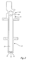
- FIG. 2 is a close-up cross-sectional view of the vertical shaft pumping system of FIG. 1 .
- FIG. 3B is a cross-sectional view of the impeller of FIG. 3A .
- FIG. 3D is a top view of the impeller of FIG. 3A .
- Upper scroll and bearing elements 12 of scroll compressor 10 require lubrication.
- the lubricant contained in lubricant reservoir 18 can be used for this purpose.
- Vertical shaft 20 is positioned so that lower end 22 with impeller 30 sit in lubricant reservoir 18. This enables lubricant to enter vertical shaft through central hole 36 in impeller 30.
- Shaft 20 is attached to motor rotor 14 by a press-fit or other method generally known in the art.
- Motor rotor 14 rotates vertical shaft 20 with impeller 30. This rotation creates a vortex with centrifugal force causing lubricants to travel upward from reservoir 18 through central hole 36 of impeller 30, and through vertical shaft 20 to upper end 24 of shaft 20.
- Lubricants then exit vertical shaft 20 in the radial direction through one or more holes 26 to lubricate upper scroll and bearing elements 12.
- FIG. 2 is a close-up cross-sectional view of the vertical shaft pumping system of FIG. 1 , and includes shaft 20 with lower end 22, upper end 24 with one or more holes 26, inner bore 28 and impeller 30 (with lower surface 34 and central hole 36).
- Impeller 30 is located at lower end 22 of inner bore 28 of shaft 20 and lower surface 34 of impeller 30 generally sits flush with the end of shaft 20.
- Impeller 30 can be integral to shaft 20 or can be pressed, welded, soldered, brazed or bonded into the shaft 20. The outer circumference of impeller 30 is against the inner wall of inner bore 28 of shaft 20 if it is an insert.
- Impeller 30 assists in helping the lubricant travel up vertical shaft 20 by increasing the rotational velocity of the lubricant being vertically pumped up through central hole 36 in impeller 30. This increase in rotational velocity creates a uniform vortex of lubricant through centrifugal force. This uniform vortex is accomplished by increasing the tractive force at the boundary layer between the lubricant and shaft 20 through the shape and positioning of impeller 30.
- FIG. 3A is a perspective view of an impeller according to the present invention.
- FIG. 3B is a cross-sectional view of the impeller of FIG. 3A.
- FIGS. 3C are bottom and top views, respectively, of the impeller of FIG. 3A .
- Impeller 30 includes cylindrical base section 32 with outer circumference 33, lower surface 34, central hole 36, and upper teeth 38 formed by slots 42.
- Upper teeth 38 include angled upper surfaces 40.
- Central hole 36 goes from lower surface 34 through upper surface of pump impeller 30.
- Upper surfaces 40 are angled upward from central hole 36 to outer circumference 33. The angle can be about 50 degrees from vertical, but may be more or less depending on system requirements. Alternatively, in some applications, upper surfaces 40 may not be angled, and upper surfaces 40 and lower surface 34 would be parallel.
- Slots 42 are located radially around pump impeller 30 extending from upper surfaces 40 towards lower surface 34 to form teeth 38 on top of base portion 32. The embodiment shown in FIGS.
- Pump impeller 30 is located at the base of shaft 20 and sits in lubricant reservoir 18 (see FIGS. 1-2 ).
- Lubricant enters shaft 20 through central hole 36.
- Shaft 20 rotates, and impeller 30 with slots 42 and teeth 38 with angled upper surfaces 40 help to increase tractive force at the boundary layer between the lubricant being vertically pumped and shaft 20, thereby increasing the rotational velocity of the lubricant in shaft 20.
- the pumping effectiveness can be further enhanced by roughening the inner surface of the inner bore of the shaft to increase the tractive force. Such a condition will tend to increase the rotating speed of the lubricant film to more closely match that of the shaft. Roughening can be done by adding rifling or superficial surface irregularities, or any other suitable method.
- the vertical pumping system of the current invention uses a pump impeller to accomplish pumping of a liquid using a light-weight uniform hollow shaft.
- the pump impeller includes a central hole which the liquid enters and includes slots and teeth to increase tractive force while rotating. This helps to create a uniform vortex of lubricant with centrifugal action. It can also include angled upper surfaces on the teeth to further increase tractive forces, resulting in increased rotational velocity of the lubricant being pumped in the shaft, therefore further improving pumping. Because it is a passive pumping system (not requiring additional moving pumping elements), reliability and durability are maximized.
- the current invention also has minimal manufacturing costs compared to past systems using shafts with eccentric holes which were difficult and costly to manufacture.
Landscapes
- Engineering & Computer Science (AREA)
- Mechanical Engineering (AREA)
- General Engineering & Computer Science (AREA)
- Structures Of Non-Positive Displacement Pumps (AREA)
Abstract
Description
- Vapor cycle refrigeration systems are used to control the temperature of many commercial and household refrigeration systems. They often utilize electric motor driven scroll compressors that require oil lubrication. Vapor cycle scroll compressors (or other vertically mounted rotating machinery) generally rely on lubricating oil distribution by oil entrained in the refrigerant being circulated throughout the system. When more positive pumping is required, it is often accomplished by having the lower end of a vertical rotating shaft extend into a lubricant reservoir. In some applications the vertical shaft can incorporate an eccentric hole along its length to accomplish a pumping action to lift oil from a lower reservoir section into and through the shaft. Oil then egresses the shaft through holes at its upper end to lubricate the elevated elements. Because the shaft is vertical in the system, a reservoir of oil and refrigerant often forms in lower portions of the unit.
- A vertical shaft pumping system includes a hollow shaft with an inner bore, an inlet end and an outlet end, the outlet end with at least one liquid distribution hole. It further includes an impeller positioned at the inlet end of the shaft, with a cylindrical base portion with a lower end, a central hole for drawing fluid into the shaft, and a plurality of teeth extending upwards from the cylindrical base portion and extending radially from the central hole to the outer cylindrical circumference for increasing tractive force of liquid in the shaft when the impeller and shaft are rotating; and a motor for rotating the shaft with the impeller to centrifugally pump a liquid vertically in the shaft from the inlet end to the outlet end.
-
FIG. 1 is view of a scroll compressor and showing a cross-sectional view of a vertical shaft pumping system according to the present invention within the scroll compressor. -
FIG. 2 is a close-up cross-sectional view of the vertical shaft pumping system ofFIG. 1 . -
FIG. 3A is a perspective view of an impeller according to the present invention. -
FIG. 3B is a cross-sectional view of the impeller ofFIG. 3A . -
FIG. 3C is a bottom view of the impeller ofFIG. 3A . -
FIG. 3D is a top view of the impeller ofFIG. 3A . -
FIG. 1 is view of a scroll compressor and showing a cross-sectional view of a vertical shaft pumping system according to the present invention within the scroll compressor.Scroll compressor 10 includes upper scroll and bearingelements 12,motor rotor 14 andstator 16,lubricant reservoir 18, and vertical shaft 20 (withlower end 22,upper end 24, at least onehole 26 inupper end 24,inner bore 28 andimpeller 30 with central hole 36).Lower end 22 ofvertical shaft 20 extends intolubricant reservoir 18. - Upper scroll and bearing
elements 12 ofscroll compressor 10 require lubrication. The lubricant contained inlubricant reservoir 18 can be used for this purpose.Vertical shaft 20 is positioned so thatlower end 22 withimpeller 30 sit inlubricant reservoir 18. This enables lubricant to enter vertical shaft throughcentral hole 36 inimpeller 30.Shaft 20 is attached tomotor rotor 14 by a press-fit or other method generally known in the art.Motor rotor 14 rotatesvertical shaft 20 withimpeller 30. This rotation creates a vortex with centrifugal force causing lubricants to travel upward fromreservoir 18 throughcentral hole 36 ofimpeller 30, and throughvertical shaft 20 toupper end 24 ofshaft 20. Lubricants then exitvertical shaft 20 in the radial direction through one ormore holes 26 to lubricate upper scroll and bearingelements 12. -
FIG. 2 is a close-up cross-sectional view of the vertical shaft pumping system ofFIG. 1 , and includesshaft 20 withlower end 22,upper end 24 with one ormore holes 26,inner bore 28 and impeller 30 (withlower surface 34 and central hole 36).Impeller 30 is located atlower end 22 ofinner bore 28 ofshaft 20 andlower surface 34 ofimpeller 30 generally sits flush with the end ofshaft 20.Impeller 30 can be integral toshaft 20 or can be pressed, welded, soldered, brazed or bonded into theshaft 20. The outer circumference ofimpeller 30 is against the inner wall ofinner bore 28 ofshaft 20 if it is an insert. - Impeller 30 assists in helping the lubricant travel up
vertical shaft 20 by increasing the rotational velocity of the lubricant being vertically pumped up throughcentral hole 36 inimpeller 30. This increase in rotational velocity creates a uniform vortex of lubricant through centrifugal force. This uniform vortex is accomplished by increasing the tractive force at the boundary layer between the lubricant andshaft 20 through the shape and positioning ofimpeller 30. - For maximum pumping in a vertical pumping system, the lubricant should rotate at the same speed as
shaft 20. However, due to the inertia of the lubricant and the boundary layer at the interface of the lubricant, the lubricant will generally rotate at a speed less thanshaft 20. Past systems incorporated eccentric holes in a vertical shaft along its length to create centrifugal action, causing the liquid to flow up through the shaft based on increasing radial position of the hole centerline. While these eccentric holes did cause the liquid to pump up the vertical shaft, they created inherent unbalance in the rotating assembly. Additionally, shafts with these eccentric holes were difficult to manufacture and control. The current invention provides a vertical pumping system that does not require additional moving parts and allows the use of a uniform hollow shaft by usingimpeller 30 to rotate withshaft 20 and increase tractive force and cause lubricant to pump vertically throughshaft 20. -
FIG. 3A is a perspective view of an impeller according to the present invention.FIG. 3B is a cross-sectional view of the impeller ofFIG. 3A. FIGS. 3C are bottom and top views, respectively, of the impeller ofFIG. 3A . -
Impeller 30 includescylindrical base section 32 withouter circumference 33,lower surface 34,central hole 36, andupper teeth 38 formed byslots 42.Upper teeth 38 include angledupper surfaces 40.Central hole 36 goes fromlower surface 34 through upper surface ofpump impeller 30.Upper surfaces 40 are angled upward fromcentral hole 36 toouter circumference 33. The angle can be about 50 degrees from vertical, but may be more or less depending on system requirements. Alternatively, in some applications,upper surfaces 40 may not be angled, andupper surfaces 40 andlower surface 34 would be parallel.Slots 42 are located radially aroundpump impeller 30 extending fromupper surfaces 40 towardslower surface 34 to formteeth 38 on top ofbase portion 32. The embodiment shown inFIGS. 3A-3B includes fourslots 42 spaced equidistant radially aroundimpeller 30 to form fourteeth 38.Impeller 30 may include more orfewer slots 42 andteeth 38 depending on system requirements. Dimensions ofpump impeller 30, including central hole; outer circumference; cylindrical base section; number, shape and size of teeth; angles of upper surface; etc; may vary depending upon factors such as inner diameter of the pumping shaft, shaft speed of rotation, surface conditions of the inner diameter of pump shaft, the height to which liquid must be pumped in the shaft, the amount of liquid to be pumped up the shaft, properties of the liquid being pumped, depth the shaft extends into the liquid, and depth of liquid below the shaft.Impeller 30 can be made of plastic or any other material compatible with pumping system and liquid to be pumped. -
Pump impeller 30 is located at the base ofshaft 20 and sits in lubricant reservoir 18 (seeFIGS. 1-2 ). Lubricant entersshaft 20 throughcentral hole 36.Shaft 20 rotates, andimpeller 30 withslots 42 andteeth 38 with angledupper surfaces 40 help to increase tractive force at the boundary layer between the lubricant being vertically pumped andshaft 20, thereby increasing the rotational velocity of the lubricant inshaft 20. This creates a uniform vortex of lubricant for more effective and efficient vertical pumping out of a reservoir without requiring additional mechanical parts. The pumping effectiveness can be further enhanced by roughening the inner surface of the inner bore of the shaft to increase the tractive force. Such a condition will tend to increase the rotating speed of the lubricant film to more closely match that of the shaft. Roughening can be done by adding rifling or superficial surface irregularities, or any other suitable method. - In summary, the vertical pumping system of the current invention uses a pump impeller to accomplish pumping of a liquid using a light-weight uniform hollow shaft. The pump impeller includes a central hole which the liquid enters and includes slots and teeth to increase tractive force while rotating. This helps to create a uniform vortex of lubricant with centrifugal action. It can also include angled upper surfaces on the teeth to further increase tractive forces, resulting in increased rotational velocity of the lubricant being pumped in the shaft, therefore further improving pumping. Because it is a passive pumping system (not requiring additional moving pumping elements), reliability and durability are maximized. The current invention also has minimal manufacturing costs compared to past systems using shafts with eccentric holes which were difficult and costly to manufacture.
- While the invention has been discussed in relation to use in a scroll compressor, it can be adapted into other vertically oriented rotating assemblies. Angles and dimensions of pump impeller are shown for example purposes only, and can be varied depending on system requirements.
- While the invention has been described with reference to an exemplary embodiment(s), it will be understood by those skilled in the art that various changes may be made and equivalents may be substituted for elements thereof without departing from the scope of the invention. In addition, many modifications may be made to adapt a particular situation or material to the teachings of the invention without departing from the essential scope thereof. Therefore, it is intended that the invention not be limited to the particular embodiment(s) disclosed, but that the invention will include all embodiments falling within the scope of the appended claims.
Claims (15)
- A pump shaft for centrifugally pumping a liquid comprising:a hollow shaft with an inner bore, an inlet end and an outlet end, the outlet end having at least one liquid distribution hole; andan impeller positioned at the inlet end of the inner bore and having a central hole for drawing fluid into the hollow shaft, a cylindrical outer circumference, a lower surface, an upper surface, and a plurality of slots formed in the upper surface and extending towards the lower surface and/or a plurality of upwardly extending teeth, the slots and/or teeth extending radially from the central hole to the cylindrical outer circumference.
- The pump shaft of claim 1, wherein the upper surface of the impeller is angled in the radial direction.
- The impeller of claim 1 or 2, wherein the upper surface is angled upward from the central hole to the outer circumference.
- The impeller of claim 3, wherein the upper surface is angled upward at about 50 degrees from vertical.
- The impeller of claim 1, 2, 3 or 4, wherein the plurality of teeth are radially oriented and approximately equally spaced.
- The pump shaft of claim 1, wherein the upper surface of the impeller is parallel with the lower surface of the impeller.
- The pump shaft of any preceding claim, wherein the impeller is an integral part of the hollow shaft.
- The pump shaft of any of claims 1 to 6, wherein the impeller is fabricated separately from the hollow shaft and is inserted into it.
- The pump shaft of claim 1, wherein the plurality of slots are pairs of slots which radially mirror each other in the impeller, and /or wherein the impeller includes four slots spaced equidistant around the circumference of the impeller.
- The pump shaft of any preceding claim, wherein the impeller has a greater length from the lower surface to the upper surface at the outer circumference than at the central hole.
- The pump shaft of any preceding claim, wherein the inner bore surface is roughened.
- A vertical shaft pumping system comprising a pump shaft as claimed in any preceding claim, and a motor for rotating the shaft with the impeller to centrifugally pump a liquid vertically in the shaft from the inlet end to the outlet end.
- An impeller for use in a pump shaft as claimed in any of claims 1 to 11, comprising:a cylindrical base portion with an outer circumference adapted to sit against the shaft inner bore so that the impeller rotates when the shaft rotates and a lower end arranged to be located on the inlet end of the shaft;a central hole for drawing fluid into the pump shaft; anda plurality of teeth extending upwards from the cylindrical base portion and extending radially from the central hole to the outer circumference for increasing tractive force of liquid in the pump shaft when the impeller is rotating with the shaft, each of the plurality of teeth having an upper surface.
- A method of operating a vertical shaft pumping system, the method comprising:positioning a vertical shaft with an impeller at a lower end of the shaft so that the lower end of the shaft is immersed in a lubricant reservoir; androtating the shaft so that lubricant in the lubricant reservoir is drawn into the shaft through the impeller and vertically pumped up the shaft through centrifugal action.
- The method of claim 14, wherein the impeller comprises:a cylindrical base portion with an outer circumference that sits against the shaft inner bore so that the impeller rotates when the shaft rotates and a lower end that is located on the inlet end of the shaft;a central hole for drawing fluid into the pump shaft; anda plurality of teeth extending upwards from the cylindrical base portion and extending radially from the central hole to the outer circumference for increasing tractive force of liquid in the pump shaft when the impeller is rotating with the shaft, each of the plurality of teeth with an upper surface.
Priority Applications (1)
| Application Number | Priority Date | Filing Date | Title |
|---|---|---|---|
| EP11189852.4A EP2594798B1 (en) | 2011-11-18 | 2011-11-18 | Vertical shaft pumping system |
Applications Claiming Priority (1)
| Application Number | Priority Date | Filing Date | Title |
|---|---|---|---|
| EP11189852.4A EP2594798B1 (en) | 2011-11-18 | 2011-11-18 | Vertical shaft pumping system |
Publications (2)
| Publication Number | Publication Date |
|---|---|
| EP2594798A1 true EP2594798A1 (en) | 2013-05-22 |
| EP2594798B1 EP2594798B1 (en) | 2017-09-20 |
Family
ID=45062979
Family Applications (1)
| Application Number | Title | Priority Date | Filing Date |
|---|---|---|---|
| EP11189852.4A Active EP2594798B1 (en) | 2011-11-18 | 2011-11-18 | Vertical shaft pumping system |
Country Status (1)
| Country | Link |
|---|---|
| EP (1) | EP2594798B1 (en) |
Citations (3)
| Publication number | Priority date | Publication date | Assignee | Title |
|---|---|---|---|---|
| US3848702A (en) * | 1972-10-02 | 1974-11-19 | Copeland Corp | Lubricating system for vertical machine elements |
| US20110027117A1 (en) * | 2009-07-31 | 2011-02-03 | Fujitsu General Limited | Rotary compressor |
| US20110150690A1 (en) * | 2009-12-17 | 2011-06-23 | Industrial Technology Research Institute | Oil supply structure for refrigerant compressor |
-
2011
- 2011-11-18 EP EP11189852.4A patent/EP2594798B1/en active Active
Patent Citations (3)
| Publication number | Priority date | Publication date | Assignee | Title |
|---|---|---|---|---|
| US3848702A (en) * | 1972-10-02 | 1974-11-19 | Copeland Corp | Lubricating system for vertical machine elements |
| US20110027117A1 (en) * | 2009-07-31 | 2011-02-03 | Fujitsu General Limited | Rotary compressor |
| US20110150690A1 (en) * | 2009-12-17 | 2011-06-23 | Industrial Technology Research Institute | Oil supply structure for refrigerant compressor |
Also Published As
| Publication number | Publication date |
|---|---|
| EP2594798B1 (en) | 2017-09-20 |
Similar Documents
| Publication | Publication Date | Title |
|---|---|---|
| US8435016B2 (en) | Vertical shaft pumping system with lubricant impeller arrangement | |
| US20060013706A1 (en) | Compressor | |
| CN1079028A (en) | The oil pump that is used for variable speed hermetic compressor | |
| US3664461A (en) | Oil pump for a motor compressor | |
| JP5139531B2 (en) | Fixing device for oil pump in refrigeration compressor | |
| CN105508250A (en) | Balancing piece, rotor subassembly and rotary compressor | |
| CN101943156B (en) | Pump oil structure applied to full-closed refrigeration compressor | |
| US4730989A (en) | Rotodynamic pump with spherical bearing | |
| EP2638289B1 (en) | A hermetic compressor the lubrication performance of which is improved | |
| EP2638290B1 (en) | A hermetic compressor comprising an oil sucking member | |
| EP2594798B1 (en) | Vertical shaft pumping system | |
| US5707220A (en) | Centrifugal oil pump for a variable speed hermetic compressor | |
| CN211343340U (en) | Oil circuit structure for rotary machine and scroll compressor with same | |
| JP6967144B2 (en) | Cylindrical symmetric volumetric machine | |
| CN110360104B (en) | Oil circuit structure for rotary machinery and scroll compressor having the same | |
| US9574606B2 (en) | Thrust bearing for HVAC compressor | |
| CN103322396B (en) | Disk centrifuge high-speed bearing lubricating fitting | |
| CN201810523U (en) | Oil pumping structure applied to hermetically sealed compressor | |
| WO2015049192A1 (en) | A compressor with improved lubrication effectiveness | |
| US12549058B2 (en) | Rotary electric machine and oil ring for rotary electric machine | |
| EP3212941B1 (en) | Systems and methods to provide lubricant to a bearing | |
| JPH0652114B2 (en) | Self-lubricating bearing | |
| US20140318900A1 (en) | Pumping system and shaft for oil pumping system for hermetic compressors and compressor comprising the system and/or shaft | |
| CN102439315A (en) | Hermetic compressor having increased lubrication effectiveness | |
| KR102243682B1 (en) | Compressor |
Legal Events
| Date | Code | Title | Description |
|---|---|---|---|
| PUAI | Public reference made under article 153(3) epc to a published international application that has entered the european phase |
Free format text: ORIGINAL CODE: 0009012 |
|
| AK | Designated contracting states |
Kind code of ref document: A1 Designated state(s): AL AT BE BG CH CY CZ DE DK EE ES FI FR GB GR HR HU IE IS IT LI LT LU LV MC MK MT NL NO PL PT RO RS SE SI SK SM TR |
|
| AX | Request for extension of the european patent |
Extension state: BA ME |
|
| 17P | Request for examination filed |
Effective date: 20131122 |
|
| RBV | Designated contracting states (corrected) |
Designated state(s): AL AT BE BG CH CY CZ DE DK EE ES FI FR GB GR HR HU IE IS IT LI LT LU LV MC MK MT NL NO PL PT RO RS SE SI SK SM TR |
|
| GRAP | Despatch of communication of intention to grant a patent |
Free format text: ORIGINAL CODE: EPIDOSNIGR1 |
|
| STAA | Information on the status of an ep patent application or granted ep patent |
Free format text: STATUS: GRANT OF PATENT IS INTENDED |
|
| INTG | Intention to grant announced |
Effective date: 20170703 |
|
| GRAS | Grant fee paid |
Free format text: ORIGINAL CODE: EPIDOSNIGR3 |
|
| GRAA | (expected) grant |
Free format text: ORIGINAL CODE: 0009210 |
|
| STAA | Information on the status of an ep patent application or granted ep patent |
Free format text: STATUS: THE PATENT HAS BEEN GRANTED |
|
| AK | Designated contracting states |
Kind code of ref document: B1 Designated state(s): AL AT BE BG CH CY CZ DE DK EE ES FI FR GB GR HR HU IE IS IT LI LT LU LV MC MK MT NL NO PL PT RO RS SE SI SK SM TR |
|
| REG | Reference to a national code |
Ref country code: GB Ref legal event code: FG4D |
|
| REG | Reference to a national code |
Ref country code: CH Ref legal event code: EP |
|
| REG | Reference to a national code |
Ref country code: AT Ref legal event code: REF Ref document number: 930383 Country of ref document: AT Kind code of ref document: T Effective date: 20171015 |
|
| REG | Reference to a national code |
Ref country code: IE Ref legal event code: FG4D |
|
| REG | Reference to a national code |
Ref country code: FR Ref legal event code: PLFP Year of fee payment: 7 |
|
| REG | Reference to a national code |
Ref country code: DE Ref legal event code: R096 Ref document number: 602011041676 Country of ref document: DE |
|
| REG | Reference to a national code |
Ref country code: NL Ref legal event code: MP Effective date: 20170920 |
|
| PG25 | Lapsed in a contracting state [announced via postgrant information from national office to epo] |
Ref country code: NO Free format text: LAPSE BECAUSE OF FAILURE TO SUBMIT A TRANSLATION OF THE DESCRIPTION OR TO PAY THE FEE WITHIN THE PRESCRIBED TIME-LIMIT Effective date: 20171220 Ref country code: LT Free format text: LAPSE BECAUSE OF FAILURE TO SUBMIT A TRANSLATION OF THE DESCRIPTION OR TO PAY THE FEE WITHIN THE PRESCRIBED TIME-LIMIT Effective date: 20170920 Ref country code: SE Free format text: LAPSE BECAUSE OF FAILURE TO SUBMIT A TRANSLATION OF THE DESCRIPTION OR TO PAY THE FEE WITHIN THE PRESCRIBED TIME-LIMIT Effective date: 20170920 Ref country code: FI Free format text: LAPSE BECAUSE OF FAILURE TO SUBMIT A TRANSLATION OF THE DESCRIPTION OR TO PAY THE FEE WITHIN THE PRESCRIBED TIME-LIMIT Effective date: 20170920 Ref country code: HR Free format text: LAPSE BECAUSE OF FAILURE TO SUBMIT A TRANSLATION OF THE DESCRIPTION OR TO PAY THE FEE WITHIN THE PRESCRIBED TIME-LIMIT Effective date: 20170920 |
|
| REG | Reference to a national code |
Ref country code: LT Ref legal event code: MG4D |
|
| REG | Reference to a national code |
Ref country code: AT Ref legal event code: MK05 Ref document number: 930383 Country of ref document: AT Kind code of ref document: T Effective date: 20170920 |
|
| PG25 | Lapsed in a contracting state [announced via postgrant information from national office to epo] |
Ref country code: GR Free format text: LAPSE BECAUSE OF FAILURE TO SUBMIT A TRANSLATION OF THE DESCRIPTION OR TO PAY THE FEE WITHIN THE PRESCRIBED TIME-LIMIT Effective date: 20171221 Ref country code: RS Free format text: LAPSE BECAUSE OF FAILURE TO SUBMIT A TRANSLATION OF THE DESCRIPTION OR TO PAY THE FEE WITHIN THE PRESCRIBED TIME-LIMIT Effective date: 20170920 Ref country code: BG Free format text: LAPSE BECAUSE OF FAILURE TO SUBMIT A TRANSLATION OF THE DESCRIPTION OR TO PAY THE FEE WITHIN THE PRESCRIBED TIME-LIMIT Effective date: 20171220 Ref country code: LV Free format text: LAPSE BECAUSE OF FAILURE TO SUBMIT A TRANSLATION OF THE DESCRIPTION OR TO PAY THE FEE WITHIN THE PRESCRIBED TIME-LIMIT Effective date: 20170920 |
|
| PG25 | Lapsed in a contracting state [announced via postgrant information from national office to epo] |
Ref country code: NL Free format text: LAPSE BECAUSE OF FAILURE TO SUBMIT A TRANSLATION OF THE DESCRIPTION OR TO PAY THE FEE WITHIN THE PRESCRIBED TIME-LIMIT Effective date: 20170920 |
|
| PG25 | Lapsed in a contracting state [announced via postgrant information from national office to epo] |
Ref country code: RO Free format text: LAPSE BECAUSE OF FAILURE TO SUBMIT A TRANSLATION OF THE DESCRIPTION OR TO PAY THE FEE WITHIN THE PRESCRIBED TIME-LIMIT Effective date: 20170920 Ref country code: ES Free format text: LAPSE BECAUSE OF FAILURE TO SUBMIT A TRANSLATION OF THE DESCRIPTION OR TO PAY THE FEE WITHIN THE PRESCRIBED TIME-LIMIT Effective date: 20170920 Ref country code: CZ Free format text: LAPSE BECAUSE OF FAILURE TO SUBMIT A TRANSLATION OF THE DESCRIPTION OR TO PAY THE FEE WITHIN THE PRESCRIBED TIME-LIMIT Effective date: 20170920 Ref country code: PL Free format text: LAPSE BECAUSE OF FAILURE TO SUBMIT A TRANSLATION OF THE DESCRIPTION OR TO PAY THE FEE WITHIN THE PRESCRIBED TIME-LIMIT Effective date: 20170920 |
|
| PG25 | Lapsed in a contracting state [announced via postgrant information from national office to epo] |
Ref country code: EE Free format text: LAPSE BECAUSE OF FAILURE TO SUBMIT A TRANSLATION OF THE DESCRIPTION OR TO PAY THE FEE WITHIN THE PRESCRIBED TIME-LIMIT Effective date: 20170920 Ref country code: AT Free format text: LAPSE BECAUSE OF FAILURE TO SUBMIT A TRANSLATION OF THE DESCRIPTION OR TO PAY THE FEE WITHIN THE PRESCRIBED TIME-LIMIT Effective date: 20170920 Ref country code: IS Free format text: LAPSE BECAUSE OF FAILURE TO SUBMIT A TRANSLATION OF THE DESCRIPTION OR TO PAY THE FEE WITHIN THE PRESCRIBED TIME-LIMIT Effective date: 20180120 Ref country code: SM Free format text: LAPSE BECAUSE OF FAILURE TO SUBMIT A TRANSLATION OF THE DESCRIPTION OR TO PAY THE FEE WITHIN THE PRESCRIBED TIME-LIMIT Effective date: 20170920 Ref country code: IT Free format text: LAPSE BECAUSE OF FAILURE TO SUBMIT A TRANSLATION OF THE DESCRIPTION OR TO PAY THE FEE WITHIN THE PRESCRIBED TIME-LIMIT Effective date: 20170920 Ref country code: SK Free format text: LAPSE BECAUSE OF FAILURE TO SUBMIT A TRANSLATION OF THE DESCRIPTION OR TO PAY THE FEE WITHIN THE PRESCRIBED TIME-LIMIT Effective date: 20170920 |
|
| REG | Reference to a national code |
Ref country code: DE Ref legal event code: R097 Ref document number: 602011041676 Country of ref document: DE |
|
| PG25 | Lapsed in a contracting state [announced via postgrant information from national office to epo] |
Ref country code: MC Free format text: LAPSE BECAUSE OF FAILURE TO SUBMIT A TRANSLATION OF THE DESCRIPTION OR TO PAY THE FEE WITHIN THE PRESCRIBED TIME-LIMIT Effective date: 20170920 |
|
| PLBE | No opposition filed within time limit |
Free format text: ORIGINAL CODE: 0009261 |
|
| STAA | Information on the status of an ep patent application or granted ep patent |
Free format text: STATUS: NO OPPOSITION FILED WITHIN TIME LIMIT |
|
| PG25 | Lapsed in a contracting state [announced via postgrant information from national office to epo] |
Ref country code: LI Free format text: LAPSE BECAUSE OF NON-PAYMENT OF DUE FEES Effective date: 20171130 Ref country code: CH Free format text: LAPSE BECAUSE OF NON-PAYMENT OF DUE FEES Effective date: 20171130 Ref country code: DK Free format text: LAPSE BECAUSE OF FAILURE TO SUBMIT A TRANSLATION OF THE DESCRIPTION OR TO PAY THE FEE WITHIN THE PRESCRIBED TIME-LIMIT Effective date: 20170920 |
|
| 26N | No opposition filed |
Effective date: 20180621 |
|
| PG25 | Lapsed in a contracting state [announced via postgrant information from national office to epo] |
Ref country code: LU Free format text: LAPSE BECAUSE OF NON-PAYMENT OF DUE FEES Effective date: 20171118 |
|
| REG | Reference to a national code |
Ref country code: BE Ref legal event code: MM Effective date: 20171130 |
|
| REG | Reference to a national code |
Ref country code: IE Ref legal event code: MM4A |
|
| PG25 | Lapsed in a contracting state [announced via postgrant information from national office to epo] |
Ref country code: MT Free format text: LAPSE BECAUSE OF NON-PAYMENT OF DUE FEES Effective date: 20171118 |
|
| REG | Reference to a national code |
Ref country code: FR Ref legal event code: PLFP Year of fee payment: 8 |
|
| PG25 | Lapsed in a contracting state [announced via postgrant information from national office to epo] |
Ref country code: IE Free format text: LAPSE BECAUSE OF NON-PAYMENT OF DUE FEES Effective date: 20171118 |
|
| PG25 | Lapsed in a contracting state [announced via postgrant information from national office to epo] |
Ref country code: SI Free format text: LAPSE BECAUSE OF FAILURE TO SUBMIT A TRANSLATION OF THE DESCRIPTION OR TO PAY THE FEE WITHIN THE PRESCRIBED TIME-LIMIT Effective date: 20170920 Ref country code: BE Free format text: LAPSE BECAUSE OF NON-PAYMENT OF DUE FEES Effective date: 20171130 |
|
| PG25 | Lapsed in a contracting state [announced via postgrant information from national office to epo] |
Ref country code: HU Free format text: LAPSE BECAUSE OF FAILURE TO SUBMIT A TRANSLATION OF THE DESCRIPTION OR TO PAY THE FEE WITHIN THE PRESCRIBED TIME-LIMIT; INVALID AB INITIO Effective date: 20111118 |
|
| PG25 | Lapsed in a contracting state [announced via postgrant information from national office to epo] |
Ref country code: CY Free format text: LAPSE BECAUSE OF NON-PAYMENT OF DUE FEES Effective date: 20170920 |
|
| PG25 | Lapsed in a contracting state [announced via postgrant information from national office to epo] |
Ref country code: MK Free format text: LAPSE BECAUSE OF FAILURE TO SUBMIT A TRANSLATION OF THE DESCRIPTION OR TO PAY THE FEE WITHIN THE PRESCRIBED TIME-LIMIT Effective date: 20170920 |
|
| PG25 | Lapsed in a contracting state [announced via postgrant information from national office to epo] |
Ref country code: TR Free format text: LAPSE BECAUSE OF FAILURE TO SUBMIT A TRANSLATION OF THE DESCRIPTION OR TO PAY THE FEE WITHIN THE PRESCRIBED TIME-LIMIT Effective date: 20170920 |
|
| PG25 | Lapsed in a contracting state [announced via postgrant information from national office to epo] |
Ref country code: PT Free format text: LAPSE BECAUSE OF FAILURE TO SUBMIT A TRANSLATION OF THE DESCRIPTION OR TO PAY THE FEE WITHIN THE PRESCRIBED TIME-LIMIT Effective date: 20170920 |
|
| PG25 | Lapsed in a contracting state [announced via postgrant information from national office to epo] |
Ref country code: AL Free format text: LAPSE BECAUSE OF FAILURE TO SUBMIT A TRANSLATION OF THE DESCRIPTION OR TO PAY THE FEE WITHIN THE PRESCRIBED TIME-LIMIT Effective date: 20170920 |
|
| P01 | Opt-out of the competence of the unified patent court (upc) registered |
Effective date: 20230522 |
|
| PGFP | Annual fee paid to national office [announced via postgrant information from national office to epo] |
Ref country code: DE Payment date: 20251022 Year of fee payment: 15 |
|
| PGFP | Annual fee paid to national office [announced via postgrant information from national office to epo] |
Ref country code: GB Payment date: 20251023 Year of fee payment: 15 |
|
| PGFP | Annual fee paid to national office [announced via postgrant information from national office to epo] |
Ref country code: FR Payment date: 20251022 Year of fee payment: 15 |