EP2594797A2 - Compressor for vehicle - Google Patents
Compressor for vehicle Download PDFInfo
- Publication number
- EP2594797A2 EP2594797A2 EP20120192338 EP12192338A EP2594797A2 EP 2594797 A2 EP2594797 A2 EP 2594797A2 EP 20120192338 EP20120192338 EP 20120192338 EP 12192338 A EP12192338 A EP 12192338A EP 2594797 A2 EP2594797 A2 EP 2594797A2
- Authority
- EP
- European Patent Office
- Prior art keywords
- bearing
- rotary shaft
- shaft
- coil spring
- compressor
- Prior art date
- Legal status (The legal status is an assumption and is not a legal conclusion. Google has not performed a legal analysis and makes no representation as to the accuracy of the status listed.)
- Granted
Links
Images
Classifications
-
- F—MECHANICAL ENGINEERING; LIGHTING; HEATING; WEAPONS; BLASTING
- F04—POSITIVE - DISPLACEMENT MACHINES FOR LIQUIDS; PUMPS FOR LIQUIDS OR ELASTIC FLUIDS
- F04C—ROTARY-PISTON, OR OSCILLATING-PISTON, POSITIVE-DISPLACEMENT MACHINES FOR LIQUIDS; ROTARY-PISTON, OR OSCILLATING-PISTON, POSITIVE-DISPLACEMENT PUMPS
- F04C18/00—Rotary-piston pumps specially adapted for elastic fluids
- F04C18/02—Rotary-piston pumps specially adapted for elastic fluids of arcuate-engagement type, i.e. with circular translatory movement of co-operating members, each member having the same number of teeth or tooth-equivalents
-
- F—MECHANICAL ENGINEERING; LIGHTING; HEATING; WEAPONS; BLASTING
- F04—POSITIVE - DISPLACEMENT MACHINES FOR LIQUIDS; PUMPS FOR LIQUIDS OR ELASTIC FLUIDS
- F04C—ROTARY-PISTON, OR OSCILLATING-PISTON, POSITIVE-DISPLACEMENT MACHINES FOR LIQUIDS; ROTARY-PISTON, OR OSCILLATING-PISTON, POSITIVE-DISPLACEMENT PUMPS
- F04C23/00—Combinations of two or more pumps, each being of rotary-piston or oscillating-piston type, specially adapted for elastic fluids; Pumping installations specially adapted for elastic fluids; Multi-stage pumps specially adapted for elastic fluids
- F04C23/008—Hermetic pumps
-
- F—MECHANICAL ENGINEERING; LIGHTING; HEATING; WEAPONS; BLASTING
- F04—POSITIVE - DISPLACEMENT MACHINES FOR LIQUIDS; PUMPS FOR LIQUIDS OR ELASTIC FLUIDS
- F04C—ROTARY-PISTON, OR OSCILLATING-PISTON, POSITIVE-DISPLACEMENT MACHINES FOR LIQUIDS; ROTARY-PISTON, OR OSCILLATING-PISTON, POSITIVE-DISPLACEMENT PUMPS
- F04C18/00—Rotary-piston pumps specially adapted for elastic fluids
- F04C18/02—Rotary-piston pumps specially adapted for elastic fluids of arcuate-engagement type, i.e. with circular translatory movement of co-operating members, each member having the same number of teeth or tooth-equivalents
- F04C18/0207—Rotary-piston pumps specially adapted for elastic fluids of arcuate-engagement type, i.e. with circular translatory movement of co-operating members, each member having the same number of teeth or tooth-equivalents both members having co-operating elements in spiral form
- F04C18/0215—Rotary-piston pumps specially adapted for elastic fluids of arcuate-engagement type, i.e. with circular translatory movement of co-operating members, each member having the same number of teeth or tooth-equivalents both members having co-operating elements in spiral form where only one member is moving
-
- F—MECHANICAL ENGINEERING; LIGHTING; HEATING; WEAPONS; BLASTING
- F04—POSITIVE - DISPLACEMENT MACHINES FOR LIQUIDS; PUMPS FOR LIQUIDS OR ELASTIC FLUIDS
- F04C—ROTARY-PISTON, OR OSCILLATING-PISTON, POSITIVE-DISPLACEMENT MACHINES FOR LIQUIDS; ROTARY-PISTON, OR OSCILLATING-PISTON, POSITIVE-DISPLACEMENT PUMPS
- F04C2240/00—Components
- F04C2240/50—Bearings
- F04C2240/52—Bearings for assemblies with supports on both sides
-
- F—MECHANICAL ENGINEERING; LIGHTING; HEATING; WEAPONS; BLASTING
- F04—POSITIVE - DISPLACEMENT MACHINES FOR LIQUIDS; PUMPS FOR LIQUIDS OR ELASTIC FLUIDS
- F04C—ROTARY-PISTON, OR OSCILLATING-PISTON, POSITIVE-DISPLACEMENT MACHINES FOR LIQUIDS; ROTARY-PISTON, OR OSCILLATING-PISTON, POSITIVE-DISPLACEMENT PUMPS
- F04C2240/00—Components
- F04C2240/60—Shafts
-
- F—MECHANICAL ENGINEERING; LIGHTING; HEATING; WEAPONS; BLASTING
- F04—POSITIVE - DISPLACEMENT MACHINES FOR LIQUIDS; PUMPS FOR LIQUIDS OR ELASTIC FLUIDS
- F04C—ROTARY-PISTON, OR OSCILLATING-PISTON, POSITIVE-DISPLACEMENT MACHINES FOR LIQUIDS; ROTARY-PISTON, OR OSCILLATING-PISTON, POSITIVE-DISPLACEMENT PUMPS
- F04C2270/00—Control; Monitoring or safety arrangements
- F04C2270/12—Vibration
-
- F—MECHANICAL ENGINEERING; LIGHTING; HEATING; WEAPONS; BLASTING
- F04—POSITIVE - DISPLACEMENT MACHINES FOR LIQUIDS; PUMPS FOR LIQUIDS OR ELASTIC FLUIDS
- F04C—ROTARY-PISTON, OR OSCILLATING-PISTON, POSITIVE-DISPLACEMENT MACHINES FOR LIQUIDS; ROTARY-PISTON, OR OSCILLATING-PISTON, POSITIVE-DISPLACEMENT PUMPS
- F04C29/00—Component parts, details or accessories of pumps or pumping installations, not provided for in groups F04C18/00 - F04C28/00
- F04C29/06—Silencing
Definitions
- the present invention relates to a compressor for vehicle comprising a compression portion driven by rotating a rotary shaft.
- the scroll compressor has a fixed scroll and a movable scroll.
- the fixed scroll and the movable scroll mesh each other.
- one end of the rotary shaft is connected to the movable scroll.
- refrigerant is compressed by rotating the movable scroll around the fixed scroll.
- both end portions of the rotary shaft are rotatably supported by a bearing in the housing.
- a stress in the compression portion for example compression reaction force
- a vibration is transferred along the rotary shaft direction. If the vibration is in resonance with a vehicle side vibration, the produced noise becomes bigger.
- the Japanese Unexamined Patent Application Publication No. 3-149381 discloses a technology to reduce the noise.
- a main bearing (not shown) is supported in a main bearing member (not shown) formed in a closed container 90 (housing).
- a sub bearing 92 is supported in a sub bearing portion 91.
- crankshaft 93 rotary shaft
- the crankshaft 93 is integrally rotatably connected to a rotor 94 of a motor.
- crankshaft 93 is formed slimmer than a connection portion connected to the rotor 94.
- a stepped portion 93A is formed in the crankshaft 93 with a different diameter of the crankshaft 93.
- Awave-shaped washer 95 is located between the stepped portion 93A and the end face of an inner race 92A of the sub bearing 92.
- the wave-shaped washer 95 By the wave-shaped washer 95, an elastic force is provided toward the direction of the crankshaft 93.
- the elastic force of the wave-shaped washer 95 performs as a preload to the inner race 92A. Therefore, the vibration of the crankshaft 93 is reduced by the preload of the wave-shaped washer 95. As a result, a noise caused by resonance is reduced.
- Japanese Unexamined Patent Application Publication No. 3-149381 leaves room for a further improvement to reduce common vibrations by reducing the vibration of the crankshaft 93 by the wave-shaped washer 95.
- the compressor for vehicle of the invention provides a feature by which the vibration toward the direction of the rotary shaft is suppressed and vibration in accordance with the vehicle side vibration source is controllable to reduce resonance.
- a compressor for vehicle includes a compression portion driven by a rotary shaft in a housing.
- the compression portion is located in the housing.
- a rotary shaft is connected with the compression portion at one end.
- a motor drives the compression portion through the rotary shaft.
- a first shaft portion and a second shaft portion are formed at both ends of the rotary shaft.
- the first shaft portion is formed between the compression portion and the motor, and is supported by a first bearing.
- the second shaft portion is formed between the motor and the housing, and is supported by a second bearing.
- a coil spring is installed between either one of the first bearing or the second bearing and either one of the rotary shaft or the housing opposing one of the bearings in the axial direction of the rotary shaft.
- the advantage is that a preload is provided to the rotary shaft through either the first bearing or the second bearing, and the rotary shaft remains preloaded in the axial direction by the coil spring. Therefore, even if a vibration occurred in the compression portion and is transferred in the axial direction along the rotary shaft, the vibration of the rotary shaft is reduced by the load of the coil spring. Additionally, the controllable range of the amount of expansion and contraction of the coil spring or the amount of spring load is bigger. By controlling the range of the amount of expansion and contraction of the coil spring or the amount of spring load, even if the rotary shaft vibrates in the axial direction, a peak of frequency can be shifted. When the peak is displaced from a peak of frequency of the vehicle side vibration, common vibrations are controlled and resonance is avoided.
- the coil spring may be wound around the second shaft portion.
- the rotary shaft may form a spring supporting portion and the diameter of which may be greater than that of the second shaft portion.
- the second bearing may include an inner race.
- the coil spring may be installed between the inner race of the second bearing and the spring support portion of the rotary shaft.
- the second shaft portion may be relatively movable against the inner race of the second bearing.
- the advantage is that the vibration of the rotary shaft and common vibrations are controllable.
- the housing may form a spring supporting portion.
- the second bearing may include an outer race.
- the coil spring may be installed between the spring supporting portion of the housing and an outer race of the second bearing.
- the outer race of the second bearing is relatively movable with respect to the spring supporting portion of the housing in the axial direction.
- the advantage is that the vibration of the rotary shaft and common vibrations are controllable.
- a protruding portion may be formed between one of the bearings and the spring support portion.
- the protruding portion may engage with the coil spring.
- the advantage is that the coil spring is prevented from dropping out from the rotary shaft by being engaged with the protruding portion at one end of the coil spring. Therefore, during assembly of the scroll compressor, when the rotary shaft with the coil spring is moved, the coil spring is prevented from dropping out from the rotary shaft.
- the coil spring may be installed in a compressed state.
- the advantage is that the preload is provided to the rotary shaft through either the first bearing or the second bearing by the return power from the compressed state of the coil spring, and the rotary shaft remains loaded.
- the compression portion may be a scroll-type.
- the advantage is that the vibration of a shaft of the scroll-type compression portion is controllable steadily.
- a bearing support may be formed in the housing.
- the second bearing may be supported by being installed in the bearing support.
- the advantage is that the vibration of the rotary shaft steadily is controllable.
- a housing 11 of a scroll compressor 10 has a first housing member 11Awhich is formed cylindrical with a bottom plate, and a second housing member 11B which is formed cylindrical with a lid.
- the first and second housing member 11A, 11B are fixed, for example, by bolts.
- the scroll compressor 10 is installed in a vehicle.
- a suction port 14 for sucking fluid (refrigerant) compressed in the scroll compressor 10 is formed in the first housing member 11A.
- a rotary shaft 15 is located inside the first housing member 11A. One end portion of the rotary shaft 15 is rotatably supported by a first bearing 16. The other end portion of the rotary shaft 15 is rotatably supported by a second bearing 17.
- a rotor 20 in which a magnet is buried is integrally rotatably connected to the rotary shaft 15.
- a stator 21 is fixed surrounding the rotor 20 in an inner peripheral surface of the first housing member 11A.
- an electric motor 23 has the rotary shaft 15, the rotor 20, and the stator 21.
- a partition 25 which forms one part of the housing 11 is fixedly installed in the first housing 11A.
- a motor accommodation chamber 24 is defined in the housing 11 by the partition 25.
- the first bearing 16 which supports one end portion of the rotary shaft 15 is supported in an inner peripheral surface of the partition 25 (housing 11).
- a seal member 22 is installed in an inner periphery surface of the partition 25. The seal member 22 seals a space between outer periphery surface of the rotary shaft 15 and inner periphery surface of the partition 25.
- an eccentric shaft H is supported at the position that deviated from a central axis L as the center of the rotary shaft 15.
- a bush 26 which is formed cylindrical with a lid is rotatably supported in the eccentric shaft H.
- a movable scroll 27 is rotatably supported at one end of the rotary shaft 15.
- the movable scroll 27 has a discoidal movable side end wall 27A, a movable spiral wrap 27B which projects from the movable side end wall 27A to the second housing member 11B, and a cylindrical supporting tube portion 27C which projects from the movable side end wall 27A to the partition 25.
- a third bearing 29 is supported in the supporting tube portion 27C.
- the bush 26 is rotatably supported in the third bearing 29. The bush 26 revolves together with the eccentric shaft H around the center axis L by turning the rotary shaft 15.
- a plurality of rotation blocking element 42 (only one element is shown in Fig.1 ) are inserted and are fixed in the partition 25 which faces the movable side end wall 27A of the movable scroll 27.
- a revolution position restricting hole 41 in which the rotation blocking element 42 is inserted is formed in the movable side end wall 27A.
- the fixed scroll 31 is formed so as to face the movable scroll 27 at the side of the partition 25 where the end face of the second housing member 11B is located.
- the fixed scroll 31 has a integrally discoid fixed side end wall 31A and a fixed spiral wrap 31B which projects from the fixed side end wall 31A to the movable scroll 27.
- the movable spiral wrap 27B of the movable scroll 27 and the fixed spiral wrap 31B of the fixed scroll 31 mesh each other.
- a compression chamber 33 as a capacity changeable operating chamber is laid out between the movable scroll 27 and the fixed scroll 31.
- the movable scroll 27 is provided between the partition 25 and the fixed scroll 31.
- a back pressure chamber 32 is laid out between the movable side end wall 27A of the movable scroll 27 and an inner periphery of the partition 25.
- a high-pressure gas is sucked in the back pressure chamber 32.
- the movable scroll 27 is pushed to the fixed scroll 31 along the axial direction of the rotary shaft 15 by the high-pressure gas.
- the back pressure chamber 32 is hermetically sealed by the seal member 22.
- a suction chamber 35 for taking a refrigerant into a compression chamber 33 is laid out between an external wall 31D of the fixed scroll 31 and the outer periphery of the movable spiral wrap 27B of the movable scroll 27.
- a discharge chamber 34 is laid out between the fixed side end wall 31A of the fixed scroll 31 and the second housing member 11B. Additionally, in the fixed scroll 31, a discharge hole 31C connecting the compression chamber 33 and the discharge chamber 34 is formed at the middle of the fixed side end wall 31A.
- a discharge valve 40 which forms a reed valve for gating a discharge hole 31C is laid out at the end face of the fixed side end wall 31A near the discharge chamber 34.
- a discharge port 11C is formed in the second housing member 11B, connecting the discharge port 11C to the suction port 14 by an external refrigerant circuit (unshown).
- a first shaft portion 15A is defined as the supporting portion of the eccentric shaft H.
- a holding portion 15B is defined as the portion to which the rotor 20 of the electric motor 23 is fixed.
- the holding portion 15B is formed with the same diameter as the first shaft portion 15A.
- a locking portion 15C is defined as the portion having a diameter greater than that of the holding portion 15B.
- the locking portion 15C is located near the first shaft portion 15A at the rotary shaft 15. The rotor 20 is prevented from pulling out toward the direction of the first shaft portion 15A by the locking portion 15C.
- a spring supporting portion 15D is formed with a taper shape at the second bearing 17 side.
- the diameter of the taper becomes smaller from the holding portion 15B to the second bearing 17.
- a second shaft portion 15F is defined as the portion having a diameter smaller than that of the spring supporting portion 15D.
- the second shaft portion 15F is supported by the second bearing 17.
- the second bearing 17 is supported by a cylindrical bearing support 11 F which is vertically arranged at the middle of the bottom of the first housing member 11A.
- the first shaft portion 15A of the rotary shaft 15 is rotatably supported by the first bearing 16.
- the first shaft portion 15A is formed between the compression portion and the electric motor 23.
- the second shaft portion 15F is rotatably supported by the second bearing 17.
- the second shaft portion 15F is formed between the electric motor 23 and the first housing 11A.
- the first bearing 16 includes a first inner race 16Awhich integrally rotates with the first shaft portion 15A, a first outer race 16B which is fixedly pressed into the partition 25, and rolling elements 16C which are arranged between the first inner race 16A and the first outer race 16B.
- the second bearing 17 includes a second inner race 17A in which the second shaft portion 15F is inserted, a second outer race 17B which is inserted into the bearing support 11 F, and rolling elements 17C which are arranged between the second inner race 17A and the second outer race 17B.
- the first bearing 16 is supported by the partition 25, in the state that the first outer race 16B moves rarely to the axial direction of the rotary shaft 15 and that the first inner race 16A has a certain space for moving together with the rotary shaft 15 in the axial direction of the rotary shaft 15.
- the second bearing 17 is supported by the bearing support 11 F wherein the second outer race 17B and the second inner race 17A have respectively a space for moving in the axial direction of the rotary shaft 15. Therefore, the rotary shaft 15 is supported by the second bearing 17 wherein the second shaft portion 15F is relatively movable with respect to the second inner race 17A in the axial direction.
- the rotary shaft 15 has a movable distance in the housing 11. The movable distance means that the first inner race 16A and the second inner race 17A are slidable relatively through the rolling element 16C, 17C against the first outer race 16B and the second outer race 17B into the direction of the rotary shaft 15.
- a protruding portion 15G which has a diameter a little larger as that of the second shaft portion 15F is formed in a circumferential direction around the whole second shaft portion 15F at a side near the spring supporting portion 15D of the second shaft portion 15F between the spring supporting portion 15D and the second bearing 17.
- a coil spring 18 is wound around in the second shaft portion 15F.
- the coil spring 18 is installed between the spring supporting portion 15D which faces to the axial direction of the rotary shaft 15 and the second inner race 17A in a compressed state.
- One end of the coil spring 18 is provided between the spring supporting portion 15D and the protruding portion 15G.
- the coil spring 18 is supported in contact with the spring supporting portion 15D.
- the other end of the coil spring 18 is supported in contact with the second inner race 17A.
- the second inner race 17A is pressed toward the bearing support 11 F by the return force of the coil spring 18 which is in a compressed state.
- a preload is provided to the coil spring 18.
- the rotary shaft 15 is pressed into the direction of the rotary shaft 15 by the preload.
- the preload is arbitrarily changeable by controlling the spring load or the amount of compression (the amount of expansion and contraction) of the coil spring 18.
- the scroll compressor 10 according to the embodiment offers the following advantages.
- the coil spring 18 is installed at one end of the rotary shaft 15. For this reason, when the coil spring 18 also rotates with the rotary shaft 15, the refrigerant gas around the coil spring 18 is agitated by the rotation of the coil spring 18. Therefore, for instance, when an inverter for controlling the electric motor 23 is located near the coil spring 18 in the scroll compressor 10, the inverter is cooled by the agitation of the refrigerant gas by the coil spring 18.
- the invention may be modified as follows.
- the coil spring 18 may be installed between the inner race 16A of the first bearing 16 and a spring supporting portion formed at the rotary shaft 15 or the partition 25.
- the coil spring 18 is located between the spring supporting portion 15D of the rotary shaft 15 and the second inner race 17A of the second bearing 17 in the embodiment.
- the invention is not limited to this structure.
- the coil spring 18 is located in the space formed by the second outer race 17B and an inner periphery of the bearing support 11F.
- the second inner race 17A is fixed integrally with the second shaft portion 15F, and the second outer race 17B is relatively movable with respect to the bearing support 11 F in the axial direction.
- the first housing member 11A opposing the second bearing 17 forms the spring supporting portion.
- the vibration to the axial direction of the rotary shaft 15 is controlled by the compress of the coil spring 18 through the second outer race 17B.
- the compressed coil spring 18 is installed between the second bearing 17 and the spring supporting portion 15D which faces the second bearing 17 in the axial direction of the rotary shaft 15 in the embodiment.
- the coil spring 18 may be arranged between the first bearing 16 and the partition 25 which faces the first bearing 16 in the axial direction of the rotary shaft 15,for instance.
- the compressed coil spring 18 is installed between the second bearing 17 and the spring supporting portion 15D which faces the second bearing 17 in the axial direction of the rotary shaft 15 in the embodiment. But the invention is not limited to this structure. An uncompressed coil spring 18 may be installed. The coil spring may be arranged between the first bearing 16 and the partition 25 which faces the first bearing 16 in the axial direction of the rotary shaft 15.
- the protruding portion 15G formed in the rotary shaft 15 may be dispensable.
- a compressor for vehicle is described as the scroll compressor applying supporting structure of the rotary shaft 15 shown in the embodiment.
- the compressor for vehicle which shows vibrations in the axial direction of the rotary shaft 15 is not limited to a scroll compressor.
- the compressor type may be a piston type or a vane type and the like.
- the compressor driven by the electric motor 23 is described as the compressor for vehicle having a supporting structure of the rotary shaft 15 described in the embodiment.
- the compressor may not be driven by an electric motor 23 but may be driven directly by a drive source of an engine and the like.
- the engine is described as the vehicle side vibration source in the embodiment.
- the vehicle side vibration source is not limited to this.
- a compression portion is rotatably connected with one end portion of a rotating shaft.
- a first shaft portion formed at one end portion of the rotating shaft is supported through a first bearing by a partition.
- a second shaft portion formed at the other end portion of the rotating shaft is supported through a second bearing by a cylindrical shaft support.
- a coil spring is interposed between a second inner race of a second bearing and a spring receiving portion of the rotating shaft which faces the second inner race in the shaft direction of the rotating shaft. The structure reduces vibration toward the shaft length direction of the rotating shaft and minimizes common vibrations together with vehicle side vibrations.
Landscapes
- Engineering & Computer Science (AREA)
- Mechanical Engineering (AREA)
- General Engineering & Computer Science (AREA)
- Applications Or Details Of Rotary Compressors (AREA)
- Rotary Pumps (AREA)
- Compressor (AREA)
- Support Of The Bearing (AREA)
Abstract
Description
- The present invention relates to a compressor for vehicle comprising a compression portion driven by rotating a rotary shaft.
- One kind of the compressor for vehicle is a scroll compressor, for example. The scroll compressor has a fixed scroll and a movable scroll. The fixed scroll and the movable scroll mesh each other. In the compressor, one end of the rotary shaft is connected to the movable scroll. In the compression portion, by turning the rotary shaft, refrigerant is compressed by rotating the movable scroll around the fixed scroll. In addition, both end portions of the rotary shaft are rotatably supported by a bearing in the housing.
- In case of such the scroll compressors, when a stress in the compression portion, for example compression reaction force, occurs in the rotary shaft direction, a vibration is transferred along the rotary shaft direction. If the vibration is in resonance with a vehicle side vibration, the produced noise becomes bigger. The Japanese Unexamined Patent Application Publication No.
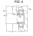
3-149381 Fig. 4 , a main bearing (not shown) is supported in a main bearing member (not shown) formed in a closed container 90 (housing). A sub bearing 92 is supported in asub bearing portion 91. One end portion of a main shaft (not shown) in a crankshaft 93 (rotary shaft) is rotatably supported, and the other end portion of the main shaft is rotatably supported by the sub bearing 92. Thecrankshaft 93 is integrally rotatably connected to arotor 94 of a motor. - Additionally, the other portion of the
crankshaft 93 is formed slimmer than a connection portion connected to therotor 94. Astepped portion 93A is formed in thecrankshaft 93 with a different diameter of thecrankshaft 93. Awave-shaped washer 95 is located between thestepped portion 93A and the end face of aninner race 92A of the sub bearing 92. - By the wave-shaped washer 95, an elastic force is provided toward the direction of the
crankshaft 93. The elastic force of the wave-shaped washer 95 performs as a preload to theinner race 92A. Therefore, the vibration of thecrankshaft 93 is reduced by the preload of the wave-shaped washer 95. As a result, a noise caused by resonance is reduced. - However, the Japanese Unexamined Patent Application Publication No.
3-149381 crankshaft 93 by the wave-shaped washer 95. - The compressor for vehicle of the invention provides a feature by which the vibration toward the direction of the rotary shaft is suppressed and vibration in accordance with the vehicle side vibration source is controllable to reduce resonance.
- The object is solved by the features of claim 1.
- In accordance with the present invention, a compressor for vehicle includes a compression portion driven by a rotary shaft in a housing. The compression portion is located in the housing. A rotary shaft is connected with the compression portion at one end. A motor drives the compression portion through the rotary shaft. A first shaft portion and a second shaft portion are formed at both ends of the rotary shaft. The first shaft portion is formed between the compression portion and the motor, and is supported by a first bearing. The second shaft portion is formed between the motor and the housing, and is supported by a second bearing. A coil spring is installed between either one of the first bearing or the second bearing and either one of the rotary shaft or the housing opposing one of the bearings in the axial direction of the rotary shaft.
- The advantage is that a preload is provided to the rotary shaft through either the first bearing or the second bearing, and the rotary shaft remains preloaded in the axial direction by the coil spring. Therefore, even if a vibration occurred in the compression portion and is transferred in the axial direction along the rotary shaft, the vibration of the rotary shaft is reduced by the load of the coil spring. Additionally, the controllable range of the amount of expansion and contraction of the coil spring or the amount of spring load is bigger. By controlling the range of the amount of expansion and contraction of the coil spring or the amount of spring load, even if the rotary shaft vibrates in the axial direction, a peak of frequency can be shifted. When the peak is displaced from a peak of frequency of the vehicle side vibration, common vibrations are controlled and resonance is avoided.
- In accordance with the present invention, the coil spring may be wound around the second shaft portion. The rotary shaft may form a spring supporting portion and the diameter of which may be greater than that of the second shaft portion. The second bearing may include an inner race. The coil spring may be installed between the inner race of the second bearing and the spring support portion of the rotary shaft. The second shaft portion may be relatively movable against the inner race of the second bearing.
- The advantage is that the vibration of the rotary shaft and common vibrations are controllable.
- In accordance with the present invention, the housing may form a spring supporting portion. The second bearing may include an outer race. The coil spring may be installed between the spring supporting portion of the housing and an outer race of the second bearing. The outer race of the second bearing is relatively movable with respect to the spring supporting portion of the housing in the axial direction.
- The advantage is that the vibration of the rotary shaft and common vibrations are controllable.
- In accordance with the present invention, a protruding portion may be formed between one of the bearings and the spring support portion. The protruding portion may engage with the coil spring.
- The advantage is that the coil spring is prevented from dropping out from the rotary shaft by being engaged with the protruding portion at one end of the coil spring. Therefore, during assembly of the scroll compressor, when the rotary shaft with the coil spring is moved, the coil spring is prevented from dropping out from the rotary shaft.
- In accordance with the present invention, the coil spring may be installed in a compressed state.
- The advantage is that the preload is provided to the rotary shaft through either the first bearing or the second bearing by the return power from the compressed state of the coil spring, and the rotary shaft remains loaded.
- In accordance with the present invention, the compression portion may be a scroll-type.
- The advantage is that the vibration of a shaft of the scroll-type compression portion is controllable steadily.
- In accordance with the present invention, a bearing support may be formed in the housing. The second bearing may be supported by being installed in the bearing support.
- The advantage is that the vibration of the rotary shaft steadily is controllable.
- Other aspects and advantages of the invention become apparent from the following description, taken in conjunction with the accompanying drawings, illustrating the principles of the invention by way of example.
- The invention, together with the objects and advantages thereof, may best be understood by reference to the following description of the presently preferred embodiments together with the accompanying drawings in which:
-
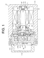
Fig. 1 is a sectional view of a scroll compressor according to an embodiment of the present invention; -
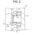
Fig. 2 is an enlarged fragmentary sectional view of a supporting structure of a rotary shaft; -
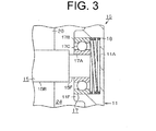
Fig. 3 is an enlarged fragmentary sectional view of a supporting structure of a rotary shaft according to an another embodiment; and -
Fig. 4 is an enlarged fragmentary sectional view according to a prior art. - The following describes an embodiment of the scroll compressor according to the compressor for vehicle of the present invention with reference to
Figs. 1 and2 . - Referring to
Fig. 1 , ahousing 11 of ascroll compressor 10 has a first housing member 11Awhich is formed cylindrical with a bottom plate, and asecond housing member 11B which is formed cylindrical with a lid. The first andsecond housing member scroll compressor 10 is installed in a vehicle. - A
suction port 14 for sucking fluid (refrigerant) compressed in thescroll compressor 10 is formed in thefirst housing member 11A. Arotary shaft 15 is located inside thefirst housing member 11A. One end portion of therotary shaft 15 is rotatably supported by afirst bearing 16. The other end portion of therotary shaft 15 is rotatably supported by asecond bearing 17. Arotor 20 in which a magnet is buried is integrally rotatably connected to therotary shaft 15. Astator 21 is fixed surrounding therotor 20 in an inner peripheral surface of thefirst housing member 11A. In the embodiment, anelectric motor 23 has therotary shaft 15, therotor 20, and thestator 21. - A
partition 25 which forms one part of thehousing 11 is fixedly installed in thefirst housing 11A. Amotor accommodation chamber 24 is defined in thehousing 11 by thepartition 25. Thefirst bearing 16 which supports one end portion of therotary shaft 15 is supported in an inner peripheral surface of the partition 25 (housing 11). Aseal member 22 is installed in an inner periphery surface of thepartition 25. Theseal member 22 seals a space between outer periphery surface of therotary shaft 15 and inner periphery surface of thepartition 25. - At one end portion of the
rotary shaft 15, an eccentric shaft H is supported at the position that deviated from a central axis L as the center of therotary shaft 15. Abush 26 which is formed cylindrical with a lid is rotatably supported in the eccentric shaft H. Amovable scroll 27 is rotatably supported at one end of therotary shaft 15. - The
movable scroll 27 has a discoidal movableside end wall 27A, amovable spiral wrap 27B which projects from the movableside end wall 27A to thesecond housing member 11B, and a cylindrical supportingtube portion 27C which projects from the movableside end wall 27A to thepartition 25. Athird bearing 29 is supported in the supportingtube portion 27C. Thebush 26 is rotatably supported in thethird bearing 29. Thebush 26 revolves together with the eccentric shaft H around the center axis L by turning therotary shaft 15. - A plurality of rotation blocking element 42 (only one element is shown in
Fig.1 ) are inserted and are fixed in thepartition 25 which faces the movableside end wall 27A of themovable scroll 27. A revolutionposition restricting hole 41 in which therotation blocking element 42 is inserted is formed in the movableside end wall 27A. The fixedscroll 31 is formed so as to face themovable scroll 27 at the side of thepartition 25 where the end face of thesecond housing member 11B is located. The fixedscroll 31 has a integrally discoid fixedside end wall 31A and a fixedspiral wrap 31B which projects from the fixedside end wall 31A to themovable scroll 27. Themovable spiral wrap 27B of themovable scroll 27 and the fixedspiral wrap 31B of the fixedscroll 31 mesh each other. Acompression chamber 33 as a capacity changeable operating chamber is laid out between themovable scroll 27 and the fixedscroll 31. - The
movable scroll 27 is provided between thepartition 25 and the fixedscroll 31. Aback pressure chamber 32 is laid out between the movableside end wall 27A of themovable scroll 27 and an inner periphery of thepartition 25. A high-pressure gas is sucked in theback pressure chamber 32. Themovable scroll 27 is pushed to the fixedscroll 31 along the axial direction of therotary shaft 15 by the high-pressure gas. Theback pressure chamber 32 is hermetically sealed by theseal member 22. - A
suction chamber 35 for taking a refrigerant into acompression chamber 33 is laid out between anexternal wall 31D of the fixedscroll 31 and the outer periphery of themovable spiral wrap 27B of themovable scroll 27. Adischarge chamber 34 is laid out between the fixedside end wall 31A of the fixedscroll 31 and thesecond housing member 11B. Additionally, in the fixedscroll 31, adischarge hole 31C connecting thecompression chamber 33 and thedischarge chamber 34 is formed at the middle of the fixedside end wall 31A. - A
discharge valve 40 which forms a reed valve for gating adischarge hole 31C is laid out at the end face of the fixedside end wall 31A near thedischarge chamber 34. Adischarge port 11C is formed in thesecond housing member 11B, connecting thedischarge port 11C to thesuction port 14 by an external refrigerant circuit (unshown). - When the
rotary shaft 15 is rotated by electrical power to theelectric motor 23, thebush 26 revolves around the central axis L of therotary shaft 15 through the eccentric shaft H. At this time, a line contact portion between themovable spiral wrap 27B and fixedspiral wrap 31B moves to the central position along the periphery surface of the fixedspiral wrap 31B. Then the capacity of thecompression chamber 33 decreases. The refrigerant taken from thesuction chamber 35 to thecompression chamber 33 is compressed. The refrigerant compressed in thecompression chamber 33 is discharged from thedischarge hole 31C through adischarge valve 40 to thedischarge chamber 34. A rotation of themovable scroll 27 is inhibited by therotation blocking element 42. In the embodiment, a scroll-type compression portion is formed by themovable scroll 27 and fixedscroll 31. - Next, the supporting structure of the
rotary shaft 15 is described. - With regard to the
rotary shaft 15, theshaft 15 is inserted into thepartition 25. Afirst shaft portion 15A is defined as the supporting portion of the eccentric shaft H. With regard to therotary shaft 15, a holdingportion 15B is defined as the portion to which therotor 20 of theelectric motor 23 is fixed. The holdingportion 15B is formed with the same diameter as thefirst shaft portion 15A. With regard to therotary shaft 15, a lockingportion 15C is defined as the portion having a diameter greater than that of the holdingportion 15B. The lockingportion 15C is located near thefirst shaft portion 15A at therotary shaft 15. Therotor 20 is prevented from pulling out toward the direction of thefirst shaft portion 15A by the lockingportion 15C. - With regard to the
rotary shaft 15, aspring supporting portion 15D is formed with a taper shape at thesecond bearing 17 side. The diameter of the taper becomes smaller from the holdingportion 15B to thesecond bearing 17. With regard to therotary shaft 15, asecond shaft portion 15F is defined as the portion having a diameter smaller than that of thespring supporting portion 15D. Thesecond shaft portion 15F is supported by thesecond bearing 17. Thesecond bearing 17 is supported by acylindrical bearing support 11 F which is vertically arranged at the middle of the bottom of thefirst housing member 11A. - The
first shaft portion 15A of therotary shaft 15 is rotatably supported by thefirst bearing 16. Thefirst shaft portion 15A is formed between the compression portion and theelectric motor 23. Thesecond shaft portion 15F is rotatably supported by thesecond bearing 17. Thesecond shaft portion 15F is formed between theelectric motor 23 and thefirst housing 11A. Thefirst bearing 16 includes a first inner race 16Awhich integrally rotates with thefirst shaft portion 15A, a firstouter race 16B which is fixedly pressed into thepartition 25, and rolling elements 16C which are arranged between the firstinner race 16A and the firstouter race 16B. Thesecond bearing 17 includes a secondinner race 17A in which thesecond shaft portion 15F is inserted, a secondouter race 17B which is inserted into the bearingsupport 11 F, and rollingelements 17C which are arranged between the secondinner race 17A and the secondouter race 17B. - The
first bearing 16 is supported by thepartition 25, in the state that the firstouter race 16B moves rarely to the axial direction of therotary shaft 15 and that the firstinner race 16A has a certain space for moving together with therotary shaft 15 in the axial direction of therotary shaft 15. Thesecond bearing 17 is supported by the bearingsupport 11 F wherein the secondouter race 17B and the secondinner race 17A have respectively a space for moving in the axial direction of therotary shaft 15. Therefore, therotary shaft 15 is supported by thesecond bearing 17 wherein thesecond shaft portion 15F is relatively movable with respect to the secondinner race 17A in the axial direction. Therotary shaft 15 has a movable distance in thehousing 11. The movable distance means that the firstinner race 16A and the secondinner race 17A are slidable relatively through the rollingelement 16C, 17C against the firstouter race 16B and the secondouter race 17B into the direction of therotary shaft 15. - As shown in
Fig.2 , a protrudingportion 15G which has a diameter a little larger as that of thesecond shaft portion 15F is formed in a circumferential direction around the wholesecond shaft portion 15F at a side near thespring supporting portion 15D of thesecond shaft portion 15F between thespring supporting portion 15D and thesecond bearing 17. Acoil spring 18 is wound around in thesecond shaft portion 15F. Thecoil spring 18 is installed between thespring supporting portion 15D which faces to the axial direction of therotary shaft 15 and the secondinner race 17A in a compressed state. One end of thecoil spring 18 is provided between thespring supporting portion 15D and the protrudingportion 15G. Thecoil spring 18 is supported in contact with thespring supporting portion 15D. The other end of thecoil spring 18 is supported in contact with the secondinner race 17A. - The second
inner race 17A is pressed toward the bearingsupport 11 F by the return force of thecoil spring 18 which is in a compressed state. A preload is provided to thecoil spring 18. Therotary shaft 15 is pressed into the direction of therotary shaft 15 by the preload. The preload is arbitrarily changeable by controlling the spring load or the amount of compression (the amount of expansion and contraction) of thecoil spring 18. - Then, the following will explain the operation of the
scroll compressor 10. - When the
rotary shaft 15 is rotated by electric power to theelectric motor 23 and themovable scroll 27 rotates around the fixedscroll 31, a refrigerant is compressed in the compression portion. Then, a vibration caused by the compression transfers to the axial direction along therotary shaft 15. At this time, a preload is provided to therotary shaft 15 by thecoil spring 18, and therotary shaft 15 remains preloaded. For this reason, the vibration of therotary shaft 15 toward the axial direction by the vibration from the compression portion is suppressed. Additionally, it is possible to shift the peak of frequency of therotary shaft 15 from the peak of frequency of the vehicle side vibration source (an engine, for instance) by reducing the preload which thecoil spring 18 provides. - The
scroll compressor 10 according to the embodiment offers the following advantages. - (1) With regard to the
scroll compressor 10 in which both ends of therotary shaft 15 are supported by thefirst bearing 16 and thesecond bearing 17, thecompressed coil spring 18 is installed between thespring supporting portion 15D in therotary shaft 15 and the secondinner race 17A of thesecond bearing 17. Additionally, the preload is provided to therotary shaft 15 by the return force when returning from the compressed condition of thecoil spring 18, and therotary shaft 15 remains tensioned. Therefore, even if a vibration by compression of the refrigerant in the compression portion is transfered in the axial direction of therotary shaft 15, the vibration of therotary shaft 15 is suppressed by the tension of thecoil spring 18. - (2) When the compressing force of the
coil spring 18 or the amount of spring load is increased, the preload provided to therotary shaft 15 becomes bigger. It becomes more difficult to slide therotary shaft 15 into the axial direction. In an opposite manner, when the compress amount of thecoil spring 18 or the amount of spring load is decreased, the preload provided to therotary shaft 15 becomes smaller, and it becomes easier to slide therotary shaft 15 into the axial direction. Additionally, by reducing the compressing force of thecoil spring 18 or the amount of spring load, it is possible to shift the peak of frequency when therotary shaft 15 is vibrated. Therefore, the controllable region of the preload is shiftable by applying thecoil spring 18. Additionally, the peak of frequency is shiftable when therotary shaft 15 vibrates from the peak of frequency of the vehicle side vibration source, and common vibrations are controllable and resonance is avoided. - (3) The
rotary shaft 15 is supported by thefirst bearing 16 and thesecond bearing 17. With regard to assembling, however, thesecond shaft portion 15F of therotary shaft 15 is respectively movably installed against the second bearing 17 (the secondinner race 17A). Thecoil spring 18 compresses the secondinner race 17A against the bearingsupport 11 so that a backlash of the secondinner race 17A is reduced. - (4) With regard to the
rotary shaft 15, the protrudingportion 15G is formed near thespring supporting portion 15D which abuts against one end of thecoil spring 18. For this reason, if thecoil spring 18 is extended in the axial direction of therotary shaft 15 which is positioned in the vertical direction during assembling in the condition that thecoil spring 18 is assembled to therotary shaft 15, thecoil spring 18 is prevented from falling from therotary shaft 15 by being held at one end between the protrudingportion 15G and one end of thecoil spring 18. Therefore, on assembling thescroll compressor 10, when therotary shaft 15 on which thecoil spring 18 is assembled is transported, thecoil spring 18 is prevented from falling from therotary shaft 15, and the work efficiency is improved. - The
coil spring 18 is installed at one end of therotary shaft 15. For this reason, when thecoil spring 18 also rotates with therotary shaft 15, the refrigerant gas around thecoil spring 18 is agitated by the rotation of thecoil spring 18. Therefore, for instance, when an inverter for controlling theelectric motor 23 is located near thecoil spring 18 in thescroll compressor 10, the inverter is cooled by the agitation of the refrigerant gas by thecoil spring 18. - (6) In the
scroll compressor 10 which has the compression portion of the scroll-type, the vibration by the compression in the compression portion is easily transferred to therotary shaft 15 through the fixedscroll 31 or thethird bearing 29 or the like. Therefore, the vibration of therotary shaft 15 is controlled by installing thecoil spring 18 to therotary shaft 15 of thescroll compressor 10. Consequently, resonance is reduced. - (7) The
first bearing 16 is press-fitted in thepartition 25. Thesecond bearing 17 is inserted and supported by the bearingsupport 11 F. Therefore, therotary shaft 15 is relatively movable with respect to the secondinner race 17A in the axial direction with being supported by thesecond bearing 17. For this reason, therotary shaft 15 is movable into the axial direction. The vibration of therotary shaft 15 is controlled by the compressing force of thecoil spring 18. - The invention may be modified as follows.
- The
coil spring 18 may be installed between theinner race 16A of thefirst bearing 16 and a spring supporting portion formed at therotary shaft 15 or thepartition 25. - The
coil spring 18 is located between thespring supporting portion 15D of therotary shaft 15 and the secondinner race 17A of thesecond bearing 17 in the embodiment. But the invention is not limited to this structure. Referring toFig.3 , thecoil spring 18 is located in the space formed by the secondouter race 17B and an inner periphery of thebearing support 11F. In this case, the secondinner race 17A is fixed integrally with thesecond shaft portion 15F, and the secondouter race 17B is relatively movable with respect to thebearing support 11 F in the axial direction. Thefirst housing member 11A opposing thesecond bearing 17 forms the spring supporting portion. In such a structure also, when therotary shaft 15 vibrates, the vibration to the axial direction of therotary shaft 15 is controlled by the compress of thecoil spring 18 through the secondouter race 17B. - The
compressed coil spring 18 is installed between thesecond bearing 17 and thespring supporting portion 15D which faces thesecond bearing 17 in the axial direction of therotary shaft 15 in the embodiment. But the invention is not limited to this structure. Thecoil spring 18 may be arranged between thefirst bearing 16 and thepartition 25 which faces thefirst bearing 16 in the axial direction of therotary shaft 15,for instance. - The
compressed coil spring 18 is installed between thesecond bearing 17 and thespring supporting portion 15D which faces thesecond bearing 17 in the axial direction of therotary shaft 15 in the embodiment. But the invention is not limited to this structure. Anuncompressed coil spring 18 may be installed. The coil spring may be arranged between thefirst bearing 16 and thepartition 25 which faces thefirst bearing 16 in the axial direction of therotary shaft 15. - The protruding
portion 15G formed in therotary shaft 15 may be dispensable. - A compressor for vehicle is described as the scroll compressor applying supporting structure of the
rotary shaft 15 shown in the embodiment. The compressor for vehicle which shows vibrations in the axial direction of therotary shaft 15 is not limited to a scroll compressor. The compressor type may be a piston type or a vane type and the like. - The compressor driven by the
electric motor 23 is described as the compressor for vehicle having a supporting structure of therotary shaft 15 described in the embodiment. However the compressor may not be driven by anelectric motor 23 but may be driven directly by a drive source of an engine and the like. - The engine is described as the vehicle side vibration source in the embodiment. However, the vehicle side vibration source is not limited to this.
- With regard to a scroll compressor, a compression portion is rotatably connected with one end portion of a rotating shaft. A first shaft portion formed at one end portion of the rotating shaft is supported through a first bearing by a partition. A second shaft portion formed at the other end portion of the rotating shaft is supported through a second bearing by a cylindrical shaft support. A coil spring is interposed between a second inner race of a second bearing and a spring receiving portion of the rotating shaft which faces the second inner race in the shaft direction of the rotating shaft. The structure reduces vibration toward the shaft length direction of the rotating shaft and minimizes common vibrations together with vehicle side vibrations.
Claims (7)
- A compressor (10) for vehicle including a housing (11),
characterized by
a compression portion located in the housing (11),
a rotary shaft (15) connected with the compression portion at one end,
a motor (23) driving the compression portion through the rotary shaft (15),
a first shaft portion (15A) and a second shaft portion (15F) formed at both ends of the rotary shaft (15),
wherein the first shaft portion (15A) is formed between the compression portion and the motor (23), and is supported by a first bearing (16),
wherein the second shaft portion (15F) is formed between the motor (23) and the housing (11), and is supported by a second bearing (17),
wherein a coil spring (18) is installed between either one of the first bearing (16) or the second bearing (17) and either one of the rotary shaft (15) or the housing (11) opposing one of the bearings (16, 17) in the axial direction of the rotary shaft (15). - The compressor (10) for vehicle according to claim 1, characterized in that,
the coil spring (18) is wound around the second shaft portion (15F),
wherein the rotary shaft (15) forms a spring supporting portion (15D) and the diameter of which is greater than that of the second shaft portion (15F),
wherein the second bearing (17) includes an inner race (17A),
wherein the coil spring (18) is installed between the inner race (17A) of the second bearing (17) and the spring support portion (15D) of the rotary shaft (15),
wherein the second shaft portion (15F) is relatively movable with respect to the inner race (17A) of the second bearing (17) in the axial direction. - The compressor (10) for vehicle according to claim 1, characterized in that
wherein the housing (11) forms a spring supporting portion,
wherein the second bearing (17) includes an outer race (17B),
wherein the coil spring (18) is installed between the spring supporting portion of the housing (11) and an outer race (17B) of the second bearing (17), wherein the outer race (17B) of the second bearing (17) is relatively movable with respect to the spring supporting portion of the housing (11) in the axial direction. - The compressor (10) for vehicle according to claim 2 or 3, characterized in that a protruding portion (15G) is formed between one of the bearings (16, 17) and the spring support portion (11, 15D),
wherein the protruding portion (15G) engages with the coil spring (18). - The compressor (10) for vehicle according to claims 1 through 4, characterized in that the coil spring (18) is installed in a compressed state.
- The compressor (10) for vehicle according to claims 1 through 5, characterized in that the compression portion is a scroll-type.
- The compressor (10) for vehicle according to claims 1 through 6, characterized in that a bearing support (11F) is formed in the housing (11),
wherein the second bearing (17) is supported by being installed in the bearing support (11 F).
Applications Claiming Priority (1)
| Application Number | Priority Date | Filing Date | Title |
|---|---|---|---|
| JP2011252814A JP5578159B2 (en) | 2011-11-18 | 2011-11-18 | Compressor for vehicle |
Publications (3)
| Publication Number | Publication Date |
|---|---|
| EP2594797A2 true EP2594797A2 (en) | 2013-05-22 |
| EP2594797A3 EP2594797A3 (en) | 2016-04-27 |
| EP2594797B1 EP2594797B1 (en) | 2017-06-07 |
Family
ID=47227556
Family Applications (1)
| Application Number | Title | Priority Date | Filing Date |
|---|---|---|---|
| EP12192338.7A Active EP2594797B1 (en) | 2011-11-18 | 2012-11-13 | Compressor for vehicle |
Country Status (5)
| Country | Link |
|---|---|
| US (1) | US9206804B2 (en) |
| EP (1) | EP2594797B1 (en) |
| JP (1) | JP5578159B2 (en) |
| KR (1) | KR101420524B1 (en) |
| CN (1) | CN103122854B (en) |
Cited By (7)
| Publication number | Priority date | Publication date | Assignee | Title |
|---|---|---|---|---|
| GB2522521A (en) * | 2013-12-11 | 2015-07-29 | Agilent Technologies Inc | Scroll pump having axial compliance system including a flexure |
| CN104806526A (en) * | 2015-04-01 | 2015-07-29 | 广东美芝制冷设备有限公司 | Rotating compressor |
| GB2523537A (en) * | 2013-12-11 | 2015-09-02 | Agilent Technologies Inc | Scroll pump having axially compliant spring element |
| CN109642571A (en) * | 2016-08-19 | 2019-04-16 | 三菱重工制冷空调系统株式会社 | Dual rotary Scrawl compressor |
| GB2520777B (en) * | 2013-12-02 | 2020-04-15 | Agilent Technologies Inc | Scroll vacuum pump having external axial adjustment mechanism |
| WO2020217066A1 (en) * | 2019-04-26 | 2020-10-29 | Edwards Limited | Scroll pump crank sleeve |
| WO2025062113A1 (en) * | 2023-09-19 | 2025-03-27 | Edwards Limited | Scroll pump |
Families Citing this family (11)
| Publication number | Priority date | Publication date | Assignee | Title |
|---|---|---|---|---|
| US9605674B2 (en) * | 2013-12-26 | 2017-03-28 | Agilent Technologies, Inc. | Vacuum scroll pump having pressure-balanced orbiting plate scroll |
| CN105443377A (en) * | 2014-06-10 | 2016-03-30 | 丹佛斯(天津)有限公司 | Scroll compressor |
| JP2017180415A (en) * | 2016-03-31 | 2017-10-05 | 株式会社豊田自動織機 | Vane type compressor |
| CN106704187A (en) * | 2017-01-24 | 2017-05-24 | 广东美芝制冷设备有限公司 | Horizontal rotary compressor and vehicle |
| JP2018135855A (en) * | 2017-02-23 | 2018-08-30 | アネスト岩田株式会社 | Scroll fluid machine and manufacturing method of the same |
| JP6961413B2 (en) | 2017-07-24 | 2021-11-05 | サンデン・オートモーティブコンポーネント株式会社 | Scroll type fluid machine |
| JP2019023439A (en) * | 2017-07-24 | 2019-02-14 | サンデン・オートモーティブコンポーネント株式会社 | Scroll Type Fluid Machine |
| JP2019210815A (en) * | 2018-05-31 | 2019-12-12 | サンデン・オートモーティブコンポーネント株式会社 | Electric scroll compressor |
| CN114320900B (en) * | 2020-09-30 | 2025-10-10 | 安徽威灵汽车部件有限公司 | Compressors, air conditioning equipment and vehicles |
| DE102021110892B3 (en) * | 2021-04-28 | 2022-09-01 | Schaeffler Technologies AG & Co. KG | Electric motor driven hydraulic pump actuator |
| US12392344B2 (en) | 2021-12-24 | 2025-08-19 | Hanon Systems | Electric compressor |
Citations (1)
| Publication number | Priority date | Publication date | Assignee | Title |
|---|---|---|---|---|
| JPH03149381A (en) | 1989-11-02 | 1991-06-25 | Matsushita Electric Ind Co Ltd | Scroll compressor |
Family Cites Families (30)
| Publication number | Priority date | Publication date | Assignee | Title |
|---|---|---|---|---|
| JPS57197755U (en) * | 1981-06-10 | 1982-12-15 | ||
| JPS62150094A (en) * | 1985-12-25 | 1987-07-04 | Hitachi Ltd | Lightweight oilless vacuum pump |
| JP2730625B2 (en) | 1986-05-30 | 1998-03-25 | 松下電器産業株式会社 | Scroll compressor |
| DE3818556A1 (en) | 1988-06-01 | 1989-12-07 | Pfeiffer Vakuumtechnik | MAGNETIC BEARING FOR A FAST ROTATING VACUUM PUMP |
| US4946353A (en) * | 1989-07-03 | 1990-08-07 | Carrier Corporation | External stator rolling rotor scroll compressor |
| JP2679480B2 (en) | 1991-11-12 | 1997-11-19 | 松下電器産業株式会社 | Scroll compressor |
| JP3379156B2 (en) | 1993-07-09 | 2003-02-17 | 松下電器産業株式会社 | Hermetic compressor |
| JPH07279841A (en) * | 1994-04-12 | 1995-10-27 | Toyota Autom Loom Works Ltd | Vibration control structure in swash type compressor |
| US5489198A (en) | 1994-04-21 | 1996-02-06 | Copeland Corporation | Scroll machine sound attenuation |
| JPH08121353A (en) * | 1994-10-26 | 1996-05-14 | Nippon Piston Ring Co Ltd | Rotary vane type pump |
| US5593294A (en) * | 1995-03-03 | 1997-01-14 | Copeland Corporation | Scroll machine with reverse rotation protection |
| JPH094696A (en) * | 1995-06-19 | 1997-01-07 | Yuji Kase | Limited slip differential gear |
| JPH09119386A (en) * | 1995-10-26 | 1997-05-06 | Mitsubishi Electric Corp | Scroll compressor |
| JPH11332165A (en) | 1998-05-15 | 1999-11-30 | Asmo Co Ltd | Bearing structure for motor |
| JP2000097168A (en) * | 1998-09-21 | 2000-04-04 | Sanyo Electric Co Ltd | Oilless scroll fluid machine |
| JP3614694B2 (en) * | 1999-01-22 | 2005-01-26 | 松下電器産業株式会社 | Method and apparatus for applying pressure to both-end bearing structure of direct drive shaft of motor and hermetic compressor using them |
| JP2001263236A (en) * | 2000-03-21 | 2001-09-26 | Sanyo Electric Co Ltd | Refrigerant compressor |
| JP2002257057A (en) | 2001-02-28 | 2002-09-11 | Tokico Ltd | Scroll type fluid machine |
| JP2003202018A (en) | 2001-10-22 | 2003-07-18 | Nsk Ltd | Rolling bearing device |
| JP2003227476A (en) * | 2002-02-05 | 2003-08-15 | Matsushita Electric Ind Co Ltd | Air supply device |
| JP4130113B2 (en) | 2002-10-07 | 2008-08-06 | 株式会社デンソー | Scroll compressor |
| DE602004026307D1 (en) * | 2003-06-17 | 2010-05-12 | Panasonic Corp | AIR SUPPLY DEVICE |
| JP2005240747A (en) | 2004-02-27 | 2005-09-08 | Matsushita Electric Ind Co Ltd | Vane rotary vacuum pump |
| CN100462559C (en) * | 2004-06-28 | 2009-02-18 | 松下电器产业株式会社 | air pump |
| BE1016733A3 (en) | 2005-08-25 | 2007-05-08 | Atlas Copco Airpower Nv | IMPROVED LOW PRESSURE SCREW COMPRESSOR. |
| KR20070067310A (en) * | 2005-12-23 | 2007-06-28 | 엘지전자 주식회사 | Noise Reduction Structure of Scroll Compressor |
| JP2008008166A (en) * | 2006-06-28 | 2008-01-17 | Matsushita Electric Ind Co Ltd | Scroll type fluid machine |
| JP2010159740A (en) * | 2008-12-11 | 2010-07-22 | Toyota Industries Corp | Rotating vacuum pump |
| KR20110101495A (en) * | 2010-03-08 | 2011-09-16 | 엘지전자 주식회사 | Compressor and Refrigerating Equipment |
| GB2481839B (en) * | 2010-07-08 | 2017-03-22 | Edwards Ltd | An axially flexible pump bearing carrier |
-
2011
- 2011-11-18 JP JP2011252814A patent/JP5578159B2/en active Active
-
2012
- 2012-11-13 EP EP12192338.7A patent/EP2594797B1/en active Active
- 2012-11-16 KR KR20120130571A patent/KR101420524B1/en active Active
- 2012-11-16 CN CN201210466582.3A patent/CN103122854B/en active Active
- 2012-11-16 US US13/679,326 patent/US9206804B2/en active Active
Patent Citations (1)
| Publication number | Priority date | Publication date | Assignee | Title |
|---|---|---|---|---|
| JPH03149381A (en) | 1989-11-02 | 1991-06-25 | Matsushita Electric Ind Co Ltd | Scroll compressor |
Cited By (11)
| Publication number | Priority date | Publication date | Assignee | Title |
|---|---|---|---|---|
| GB2520777B (en) * | 2013-12-02 | 2020-04-15 | Agilent Technologies Inc | Scroll vacuum pump having external axial adjustment mechanism |
| GB2522521A (en) * | 2013-12-11 | 2015-07-29 | Agilent Technologies Inc | Scroll pump having axial compliance system including a flexure |
| GB2523537A (en) * | 2013-12-11 | 2015-09-02 | Agilent Technologies Inc | Scroll pump having axially compliant spring element |
| US9360013B2 (en) | 2013-12-11 | 2016-06-07 | Agilent Technologies, Inc. | Scroll pump having axially compliant spring element |
| US9429020B2 (en) | 2013-12-11 | 2016-08-30 | Agilent Technologies, Inc. | Scroll pump having axially compliant spring element |
| GB2522521B (en) * | 2013-12-11 | 2020-04-15 | Agilent Technologies Inc | Scroll pump having axial compliance system including a flexure |
| CN104806526A (en) * | 2015-04-01 | 2015-07-29 | 广东美芝制冷设备有限公司 | Rotating compressor |
| CN104806526B (en) * | 2015-04-01 | 2017-03-01 | 广东美芝制冷设备有限公司 | rotary compressor |
| CN109642571A (en) * | 2016-08-19 | 2019-04-16 | 三菱重工制冷空调系统株式会社 | Dual rotary Scrawl compressor |
| WO2020217066A1 (en) * | 2019-04-26 | 2020-10-29 | Edwards Limited | Scroll pump crank sleeve |
| WO2025062113A1 (en) * | 2023-09-19 | 2025-03-27 | Edwards Limited | Scroll pump |
Also Published As
| Publication number | Publication date |
|---|---|
| EP2594797B1 (en) | 2017-06-07 |
| KR20130055545A (en) | 2013-05-28 |
| CN103122854B (en) | 2015-12-23 |
| JP2013108390A (en) | 2013-06-06 |
| US9206804B2 (en) | 2015-12-08 |
| US20130129551A1 (en) | 2013-05-23 |
| EP2594797A3 (en) | 2016-04-27 |
| KR101420524B1 (en) | 2014-07-16 |
| CN103122854A (en) | 2013-05-29 |
| JP5578159B2 (en) | 2014-08-27 |
Similar Documents
| Publication | Publication Date | Title |
|---|---|---|
| US9206804B2 (en) | Compressor for vehicle with reduced vibrations | |
| US12031441B2 (en) | Multi-bearing scroll compressor to enhance load management | |
| US6746217B2 (en) | Reciprocating compressor | |
| US7384250B2 (en) | Oil discharge preventing apparatus of scroll compressor | |
| US9145890B2 (en) | Rotary compressor with dual eccentric portion | |
| US9879678B2 (en) | Scroll compressor | |
| US11710992B2 (en) | Motor and compressor including the same | |
| US8029254B2 (en) | Scroll-type fluid machine having a back-pressure chamber | |
| EP2090780B1 (en) | Compressor | |
| EP2376782B1 (en) | Reciprocating compressor and refrigerating machine having the same | |
| US20130121864A1 (en) | Scroll compressor | |
| US8734142B2 (en) | Rotation preventing member of a scroll compressor | |
| CN101529098A (en) | Rotary compressor and refrigeration cycle device | |
| KR20040007673A (en) | Enclosed type compressor | |
| EP3315774A1 (en) | Hermetic electric compressor | |
| CN111734628B (en) | Scroll compressor having a discharge port | |
| KR101711540B1 (en) | Hermetic compressor | |
| JP2024545670A (en) | Electric Compressor | |
| KR101677624B1 (en) | Hermetic compressor | |
| KR20230098433A (en) | Electric compressor | |
| CN120359687A (en) | Motor, compressor and apparatus | |
| JP2020007928A (en) | Scroll compressor | |
| KR101557505B1 (en) | compressor | |
| KR100498365B1 (en) | Structure of stator in rotary compressor | |
| JP2026001142A5 (en) |
Legal Events
| Date | Code | Title | Description |
|---|---|---|---|
| PUAI | Public reference made under article 153(3) epc to a published international application that has entered the european phase |
Free format text: ORIGINAL CODE: 0009012 |
|
| 17P | Request for examination filed |
Effective date: 20121113 |
|
| AK | Designated contracting states |
Kind code of ref document: A2 Designated state(s): AL AT BE BG CH CY CZ DE DK EE ES FI FR GB GR HR HU IE IS IT LI LT LU LV MC MK MT NL NO PL PT RO RS SE SI SK SM TR |
|
| AX | Request for extension of the european patent |
Extension state: BA ME |
|
| PUAL | Search report despatched |
Free format text: ORIGINAL CODE: 0009013 |
|
| AK | Designated contracting states |
Kind code of ref document: A3 Designated state(s): AL AT BE BG CH CY CZ DE DK EE ES FI FR GB GR HR HU IE IS IT LI LT LU LV MC MK MT NL NO PL PT RO RS SE SI SK SM TR |
|
| AX | Request for extension of the european patent |
Extension state: BA ME |
|
| RIC1 | Information provided on ipc code assigned before grant |
Ipc: F04C 18/02 20060101AFI20160318BHEP |
|
| GRAP | Despatch of communication of intention to grant a patent |
Free format text: ORIGINAL CODE: EPIDOSNIGR1 |
|
| STAA | Information on the status of an ep patent application or granted ep patent |
Free format text: STATUS: GRANT OF PATENT IS INTENDED |
|
| INTG | Intention to grant announced |
Effective date: 20161216 |
|
| GRAS | Grant fee paid |
Free format text: ORIGINAL CODE: EPIDOSNIGR3 |
|
| GRAA | (expected) grant |
Free format text: ORIGINAL CODE: 0009210 |
|
| STAA | Information on the status of an ep patent application or granted ep patent |
Free format text: STATUS: THE PATENT HAS BEEN GRANTED |
|
| AK | Designated contracting states |
Kind code of ref document: B1 Designated state(s): AL AT BE BG CH CY CZ DE DK EE ES FI FR GB GR HR HU IE IS IT LI LT LU LV MC MK MT NL NO PL PT RO RS SE SI SK SM TR |
|
| REG | Reference to a national code |
Ref country code: GB Ref legal event code: FG4D |
|
| GRAA | (expected) grant |
Free format text: ORIGINAL CODE: 0009210 |
|
| REG | Reference to a national code |
Ref country code: CH Ref legal event code: EP Ref country code: AT Ref legal event code: REF Ref document number: 899447 Country of ref document: AT Kind code of ref document: T Effective date: 20170615 |
|
| REG | Reference to a national code |
Ref country code: IE Ref legal event code: FG4D |
|
| REG | Reference to a national code |
Ref country code: DE Ref legal event code: R096 Ref document number: 602012033174 Country of ref document: DE |
|
| REG | Reference to a national code |
Ref country code: NL Ref legal event code: MP Effective date: 20170607 |
|
| REG | Reference to a national code |
Ref country code: LT Ref legal event code: MG4D |
|
| PG25 | Lapsed in a contracting state [announced via postgrant information from national office to epo] |
Ref country code: HR Free format text: LAPSE BECAUSE OF FAILURE TO SUBMIT A TRANSLATION OF THE DESCRIPTION OR TO PAY THE FEE WITHIN THE PRESCRIBED TIME-LIMIT Effective date: 20170607 Ref country code: ES Free format text: LAPSE BECAUSE OF FAILURE TO SUBMIT A TRANSLATION OF THE DESCRIPTION OR TO PAY THE FEE WITHIN THE PRESCRIBED TIME-LIMIT Effective date: 20170607 Ref country code: FI Free format text: LAPSE BECAUSE OF FAILURE TO SUBMIT A TRANSLATION OF THE DESCRIPTION OR TO PAY THE FEE WITHIN THE PRESCRIBED TIME-LIMIT Effective date: 20170607 Ref country code: LT Free format text: LAPSE BECAUSE OF FAILURE TO SUBMIT A TRANSLATION OF THE DESCRIPTION OR TO PAY THE FEE WITHIN THE PRESCRIBED TIME-LIMIT Effective date: 20170607 Ref country code: GR Free format text: LAPSE BECAUSE OF FAILURE TO SUBMIT A TRANSLATION OF THE DESCRIPTION OR TO PAY THE FEE WITHIN THE PRESCRIBED TIME-LIMIT Effective date: 20170908 Ref country code: NO Free format text: LAPSE BECAUSE OF FAILURE TO SUBMIT A TRANSLATION OF THE DESCRIPTION OR TO PAY THE FEE WITHIN THE PRESCRIBED TIME-LIMIT Effective date: 20170907 |
|
| REG | Reference to a national code |
Ref country code: AT Ref legal event code: MK05 Ref document number: 899447 Country of ref document: AT Kind code of ref document: T Effective date: 20170607 |
|
| PG25 | Lapsed in a contracting state [announced via postgrant information from national office to epo] |
Ref country code: LV Free format text: LAPSE BECAUSE OF FAILURE TO SUBMIT A TRANSLATION OF THE DESCRIPTION OR TO PAY THE FEE WITHIN THE PRESCRIBED TIME-LIMIT Effective date: 20170607 Ref country code: SE Free format text: LAPSE BECAUSE OF FAILURE TO SUBMIT A TRANSLATION OF THE DESCRIPTION OR TO PAY THE FEE WITHIN THE PRESCRIBED TIME-LIMIT Effective date: 20170607 Ref country code: RS Free format text: LAPSE BECAUSE OF FAILURE TO SUBMIT A TRANSLATION OF THE DESCRIPTION OR TO PAY THE FEE WITHIN THE PRESCRIBED TIME-LIMIT Effective date: 20170607 Ref country code: NL Free format text: LAPSE BECAUSE OF FAILURE TO SUBMIT A TRANSLATION OF THE DESCRIPTION OR TO PAY THE FEE WITHIN THE PRESCRIBED TIME-LIMIT Effective date: 20170607 Ref country code: BG Free format text: LAPSE BECAUSE OF FAILURE TO SUBMIT A TRANSLATION OF THE DESCRIPTION OR TO PAY THE FEE WITHIN THE PRESCRIBED TIME-LIMIT Effective date: 20170907 |
|
| PG25 | Lapsed in a contracting state [announced via postgrant information from national office to epo] |
Ref country code: CZ Free format text: LAPSE BECAUSE OF FAILURE TO SUBMIT A TRANSLATION OF THE DESCRIPTION OR TO PAY THE FEE WITHIN THE PRESCRIBED TIME-LIMIT Effective date: 20170607 Ref country code: SK Free format text: LAPSE BECAUSE OF FAILURE TO SUBMIT A TRANSLATION OF THE DESCRIPTION OR TO PAY THE FEE WITHIN THE PRESCRIBED TIME-LIMIT Effective date: 20170607 Ref country code: RO Free format text: LAPSE BECAUSE OF FAILURE TO SUBMIT A TRANSLATION OF THE DESCRIPTION OR TO PAY THE FEE WITHIN THE PRESCRIBED TIME-LIMIT Effective date: 20170607 Ref country code: EE Free format text: LAPSE BECAUSE OF FAILURE TO SUBMIT A TRANSLATION OF THE DESCRIPTION OR TO PAY THE FEE WITHIN THE PRESCRIBED TIME-LIMIT Effective date: 20170607 Ref country code: AT Free format text: LAPSE BECAUSE OF FAILURE TO SUBMIT A TRANSLATION OF THE DESCRIPTION OR TO PAY THE FEE WITHIN THE PRESCRIBED TIME-LIMIT Effective date: 20170607 |
|
| PG25 | Lapsed in a contracting state [announced via postgrant information from national office to epo] |
Ref country code: IS Free format text: LAPSE BECAUSE OF FAILURE TO SUBMIT A TRANSLATION OF THE DESCRIPTION OR TO PAY THE FEE WITHIN THE PRESCRIBED TIME-LIMIT Effective date: 20171007 Ref country code: IT Free format text: LAPSE BECAUSE OF FAILURE TO SUBMIT A TRANSLATION OF THE DESCRIPTION OR TO PAY THE FEE WITHIN THE PRESCRIBED TIME-LIMIT Effective date: 20170607 Ref country code: SM Free format text: LAPSE BECAUSE OF FAILURE TO SUBMIT A TRANSLATION OF THE DESCRIPTION OR TO PAY THE FEE WITHIN THE PRESCRIBED TIME-LIMIT Effective date: 20170607 Ref country code: PL Free format text: LAPSE BECAUSE OF FAILURE TO SUBMIT A TRANSLATION OF THE DESCRIPTION OR TO PAY THE FEE WITHIN THE PRESCRIBED TIME-LIMIT Effective date: 20170607 |
|
| REG | Reference to a national code |
Ref country code: DE Ref legal event code: R097 Ref document number: 602012033174 Country of ref document: DE |
|
| PLBE | No opposition filed within time limit |
Free format text: ORIGINAL CODE: 0009261 |
|
| STAA | Information on the status of an ep patent application or granted ep patent |
Free format text: STATUS: NO OPPOSITION FILED WITHIN TIME LIMIT |
|
| PG25 | Lapsed in a contracting state [announced via postgrant information from national office to epo] |
Ref country code: DK Free format text: LAPSE BECAUSE OF FAILURE TO SUBMIT A TRANSLATION OF THE DESCRIPTION OR TO PAY THE FEE WITHIN THE PRESCRIBED TIME-LIMIT Effective date: 20170607 |
|
| 26N | No opposition filed |
Effective date: 20180308 |
|
| PG25 | Lapsed in a contracting state [announced via postgrant information from national office to epo] |
Ref country code: SI Free format text: LAPSE BECAUSE OF FAILURE TO SUBMIT A TRANSLATION OF THE DESCRIPTION OR TO PAY THE FEE WITHIN THE PRESCRIBED TIME-LIMIT Effective date: 20170607 |
|
| PG25 | Lapsed in a contracting state [announced via postgrant information from national office to epo] |
Ref country code: MC Free format text: LAPSE BECAUSE OF FAILURE TO SUBMIT A TRANSLATION OF THE DESCRIPTION OR TO PAY THE FEE WITHIN THE PRESCRIBED TIME-LIMIT Effective date: 20170607 |
|
| GBPC | Gb: european patent ceased through non-payment of renewal fee |
Effective date: 20171113 |
|
| PG25 | Lapsed in a contracting state [announced via postgrant information from national office to epo] |
Ref country code: CH Free format text: LAPSE BECAUSE OF NON-PAYMENT OF DUE FEES Effective date: 20171130 Ref country code: LI Free format text: LAPSE BECAUSE OF NON-PAYMENT OF DUE FEES Effective date: 20171130 |
|
| PG25 | Lapsed in a contracting state [announced via postgrant information from national office to epo] |
Ref country code: LU Free format text: LAPSE BECAUSE OF NON-PAYMENT OF DUE FEES Effective date: 20171113 |
|
| REG | Reference to a national code |
Ref country code: FR Ref legal event code: ST Effective date: 20180731 Ref country code: BE Ref legal event code: MM Effective date: 20171130 |
|
| REG | Reference to a national code |
Ref country code: IE Ref legal event code: MM4A |
|
| PG25 | Lapsed in a contracting state [announced via postgrant information from national office to epo] |
Ref country code: MT Free format text: LAPSE BECAUSE OF NON-PAYMENT OF DUE FEES Effective date: 20171113 |
|
| PG25 | Lapsed in a contracting state [announced via postgrant information from national office to epo] |
Ref country code: FR Free format text: LAPSE BECAUSE OF NON-PAYMENT OF DUE FEES Effective date: 20171130 Ref country code: IE Free format text: LAPSE BECAUSE OF NON-PAYMENT OF DUE FEES Effective date: 20171113 |
|
| PG25 | Lapsed in a contracting state [announced via postgrant information from national office to epo] |
Ref country code: BE Free format text: LAPSE BECAUSE OF NON-PAYMENT OF DUE FEES Effective date: 20171130 Ref country code: GB Free format text: LAPSE BECAUSE OF NON-PAYMENT OF DUE FEES Effective date: 20171113 |
|
| PG25 | Lapsed in a contracting state [announced via postgrant information from national office to epo] |
Ref country code: HU Free format text: LAPSE BECAUSE OF FAILURE TO SUBMIT A TRANSLATION OF THE DESCRIPTION OR TO PAY THE FEE WITHIN THE PRESCRIBED TIME-LIMIT; INVALID AB INITIO Effective date: 20121113 |
|
| PG25 | Lapsed in a contracting state [announced via postgrant information from national office to epo] |
Ref country code: CY Free format text: LAPSE BECAUSE OF NON-PAYMENT OF DUE FEES Effective date: 20170607 |
|
| PG25 | Lapsed in a contracting state [announced via postgrant information from national office to epo] |
Ref country code: MK Free format text: LAPSE BECAUSE OF FAILURE TO SUBMIT A TRANSLATION OF THE DESCRIPTION OR TO PAY THE FEE WITHIN THE PRESCRIBED TIME-LIMIT Effective date: 20170607 |
|
| PG25 | Lapsed in a contracting state [announced via postgrant information from national office to epo] |
Ref country code: TR Free format text: LAPSE BECAUSE OF FAILURE TO SUBMIT A TRANSLATION OF THE DESCRIPTION OR TO PAY THE FEE WITHIN THE PRESCRIBED TIME-LIMIT Effective date: 20170607 |
|
| PG25 | Lapsed in a contracting state [announced via postgrant information from national office to epo] |
Ref country code: PT Free format text: LAPSE BECAUSE OF FAILURE TO SUBMIT A TRANSLATION OF THE DESCRIPTION OR TO PAY THE FEE WITHIN THE PRESCRIBED TIME-LIMIT Effective date: 20170607 |
|
| PG25 | Lapsed in a contracting state [announced via postgrant information from national office to epo] |
Ref country code: AL Free format text: LAPSE BECAUSE OF FAILURE TO SUBMIT A TRANSLATION OF THE DESCRIPTION OR TO PAY THE FEE WITHIN THE PRESCRIBED TIME-LIMIT Effective date: 20170607 |
|
| P01 | Opt-out of the competence of the unified patent court (upc) registered |
Effective date: 20230519 |
|
| PGFP | Annual fee paid to national office [announced via postgrant information from national office to epo] |
Ref country code: DE Payment date: 20250930 Year of fee payment: 14 |