EP2594791A1 - Rotor-blade attachment method for renewable energy power generation device - Google Patents
Rotor-blade attachment method for renewable energy power generation device Download PDFInfo
- Publication number
- EP2594791A1 EP2594791A1 EP11817197.4A EP11817197A EP2594791A1 EP 2594791 A1 EP2594791 A1 EP 2594791A1 EP 11817197 A EP11817197 A EP 11817197A EP 2594791 A1 EP2594791 A1 EP 2594791A1
- Authority
- EP
- European Patent Office
- Prior art keywords
- blade
- hub
- attaching part
- generating apparatus
- power generating
- Prior art date
- Legal status (The legal status is an assumption and is not a legal conclusion. Google has not performed a legal analysis and makes no representation as to the accuracy of the status listed.)
- Granted
Links
Images

Classifications
-
- F—MECHANICAL ENGINEERING; LIGHTING; HEATING; WEAPONS; BLASTING
- F03—MACHINES OR ENGINES FOR LIQUIDS; WIND, SPRING, OR WEIGHT MOTORS; PRODUCING MECHANICAL POWER OR A REACTIVE PROPULSIVE THRUST, NOT OTHERWISE PROVIDED FOR
- F03B—MACHINES OR ENGINES FOR LIQUIDS
- F03B3/00—Machines or engines of reaction type; Parts or details peculiar thereto
- F03B3/04—Machines or engines of reaction type; Parts or details peculiar thereto with substantially axial flow throughout rotors, e.g. propeller turbines
- F03B3/06—Machines or engines of reaction type; Parts or details peculiar thereto with substantially axial flow throughout rotors, e.g. propeller turbines with adjustable blades, e.g. Kaplan turbines
-
- F—MECHANICAL ENGINEERING; LIGHTING; HEATING; WEAPONS; BLASTING
- F03—MACHINES OR ENGINES FOR LIQUIDS; WIND, SPRING, OR WEIGHT MOTORS; PRODUCING MECHANICAL POWER OR A REACTIVE PROPULSIVE THRUST, NOT OTHERWISE PROVIDED FOR
- F03B—MACHINES OR ENGINES FOR LIQUIDS
- F03B13/00—Adaptations of machines or engines for special use; Combinations of machines or engines with driving or driven apparatus; Power stations or aggregates
- F03B13/12—Adaptations of machines or engines for special use; Combinations of machines or engines with driving or driven apparatus; Power stations or aggregates characterised by using wave or tide energy
- F03B13/26—Adaptations of machines or engines for special use; Combinations of machines or engines with driving or driven apparatus; Power stations or aggregates characterised by using wave or tide energy using tide energy
- F03B13/264—Adaptations of machines or engines for special use; Combinations of machines or engines with driving or driven apparatus; Power stations or aggregates characterised by using wave or tide energy using tide energy using the horizontal flow of water resulting from tide movement
-
- F—MECHANICAL ENGINEERING; LIGHTING; HEATING; WEAPONS; BLASTING
- F03—MACHINES OR ENGINES FOR LIQUIDS; WIND, SPRING, OR WEIGHT MOTORS; PRODUCING MECHANICAL POWER OR A REACTIVE PROPULSIVE THRUST, NOT OTHERWISE PROVIDED FOR
- F03B—MACHINES OR ENGINES FOR LIQUIDS
- F03B17/00—Other machines or engines
- F03B17/06—Other machines or engines using liquid flow with predominantly kinetic energy conversion, e.g. of swinging-flap type, "run-of-river", "ultra-low head"
- F03B17/061—Other machines or engines using liquid flow with predominantly kinetic energy conversion, e.g. of swinging-flap type, "run-of-river", "ultra-low head" with rotation axis substantially in flow direction
-
- F—MECHANICAL ENGINEERING; LIGHTING; HEATING; WEAPONS; BLASTING
- F03—MACHINES OR ENGINES FOR LIQUIDS; WIND, SPRING, OR WEIGHT MOTORS; PRODUCING MECHANICAL POWER OR A REACTIVE PROPULSIVE THRUST, NOT OTHERWISE PROVIDED FOR
- F03D—WIND MOTORS
- F03D1/00—Wind motors with rotation axis substantially parallel to the air flow entering the rotor
- F03D1/06—Rotors
- F03D1/065—Rotors characterised by their construction elements
- F03D1/0658—Arrangements for fixing wind-engaging parts to a hub
-
- F—MECHANICAL ENGINEERING; LIGHTING; HEATING; WEAPONS; BLASTING
- F03—MACHINES OR ENGINES FOR LIQUIDS; WIND, SPRING, OR WEIGHT MOTORS; PRODUCING MECHANICAL POWER OR A REACTIVE PROPULSIVE THRUST, NOT OTHERWISE PROVIDED FOR
- F03D—WIND MOTORS
- F03D13/00—Assembly, mounting or commissioning of wind motors; Arrangements specially adapted for transporting wind motor components
- F03D13/10—Assembly of wind motors; Arrangements for erecting wind motors
-
- F—MECHANICAL ENGINEERING; LIGHTING; HEATING; WEAPONS; BLASTING
- F05—INDEXING SCHEMES RELATING TO ENGINES OR PUMPS IN VARIOUS SUBCLASSES OF CLASSES F01-F04
- F05B—INDEXING SCHEME RELATING TO WIND, SPRING, WEIGHT, INERTIA OR LIKE MOTORS, TO MACHINES OR ENGINES FOR LIQUIDS COVERED BY SUBCLASSES F03B, F03D AND F03G
- F05B2230/00—Manufacture
- F05B2230/60—Assembly methods
- F05B2230/604—Assembly methods using positioning or alignment devices for aligning or centering, e.g. pins
-
- F—MECHANICAL ENGINEERING; LIGHTING; HEATING; WEAPONS; BLASTING
- F05—INDEXING SCHEMES RELATING TO ENGINES OR PUMPS IN VARIOUS SUBCLASSES OF CLASSES F01-F04
- F05B—INDEXING SCHEME RELATING TO WIND, SPRING, WEIGHT, INERTIA OR LIKE MOTORS, TO MACHINES OR ENGINES FOR LIQUIDS COVERED BY SUBCLASSES F03B, F03D AND F03G
- F05B2230/00—Manufacture
- F05B2230/60—Assembly methods
- F05B2230/61—Assembly methods using auxiliary equipment for lifting or holding
-
- F—MECHANICAL ENGINEERING; LIGHTING; HEATING; WEAPONS; BLASTING
- F05—INDEXING SCHEMES RELATING TO ENGINES OR PUMPS IN VARIOUS SUBCLASSES OF CLASSES F01-F04
- F05B—INDEXING SCHEME RELATING TO WIND, SPRING, WEIGHT, INERTIA OR LIKE MOTORS, TO MACHINES OR ENGINES FOR LIQUIDS COVERED BY SUBCLASSES F03B, F03D AND F03G
- F05B2260/00—Function
- F05B2260/40—Transmission of power
- F05B2260/406—Transmission of power through hydraulic systems
-
- Y—GENERAL TAGGING OF NEW TECHNOLOGICAL DEVELOPMENTS; GENERAL TAGGING OF CROSS-SECTIONAL TECHNOLOGIES SPANNING OVER SEVERAL SECTIONS OF THE IPC; TECHNICAL SUBJECTS COVERED BY FORMER USPC CROSS-REFERENCE ART COLLECTIONS [XRACs] AND DIGESTS
- Y02—TECHNOLOGIES OR APPLICATIONS FOR MITIGATION OR ADAPTATION AGAINST CLIMATE CHANGE
- Y02E—REDUCTION OF GREENHOUSE GAS [GHG] EMISSIONS, RELATED TO ENERGY GENERATION, TRANSMISSION OR DISTRIBUTION
- Y02E10/00—Energy generation through renewable energy sources
- Y02E10/20—Hydro energy
-
- Y—GENERAL TAGGING OF NEW TECHNOLOGICAL DEVELOPMENTS; GENERAL TAGGING OF CROSS-SECTIONAL TECHNOLOGIES SPANNING OVER SEVERAL SECTIONS OF THE IPC; TECHNICAL SUBJECTS COVERED BY FORMER USPC CROSS-REFERENCE ART COLLECTIONS [XRACs] AND DIGESTS
- Y02—TECHNOLOGIES OR APPLICATIONS FOR MITIGATION OR ADAPTATION AGAINST CLIMATE CHANGE
- Y02E—REDUCTION OF GREENHOUSE GAS [GHG] EMISSIONS, RELATED TO ENERGY GENERATION, TRANSMISSION OR DISTRIBUTION
- Y02E10/00—Energy generation through renewable energy sources
- Y02E10/30—Energy from the sea, e.g. using wave energy or salinity gradient
-
- Y—GENERAL TAGGING OF NEW TECHNOLOGICAL DEVELOPMENTS; GENERAL TAGGING OF CROSS-SECTIONAL TECHNOLOGIES SPANNING OVER SEVERAL SECTIONS OF THE IPC; TECHNICAL SUBJECTS COVERED BY FORMER USPC CROSS-REFERENCE ART COLLECTIONS [XRACs] AND DIGESTS
- Y02—TECHNOLOGIES OR APPLICATIONS FOR MITIGATION OR ADAPTATION AGAINST CLIMATE CHANGE
- Y02E—REDUCTION OF GREENHOUSE GAS [GHG] EMISSIONS, RELATED TO ENERGY GENERATION, TRANSMISSION OR DISTRIBUTION
- Y02E10/00—Energy generation through renewable energy sources
- Y02E10/70—Wind energy
- Y02E10/72—Wind turbines with rotation axis in wind direction
-
- Y—GENERAL TAGGING OF NEW TECHNOLOGICAL DEVELOPMENTS; GENERAL TAGGING OF CROSS-SECTIONAL TECHNOLOGIES SPANNING OVER SEVERAL SECTIONS OF THE IPC; TECHNICAL SUBJECTS COVERED BY FORMER USPC CROSS-REFERENCE ART COLLECTIONS [XRACs] AND DIGESTS
- Y02—TECHNOLOGIES OR APPLICATIONS FOR MITIGATION OR ADAPTATION AGAINST CLIMATE CHANGE
- Y02P—CLIMATE CHANGE MITIGATION TECHNOLOGIES IN THE PRODUCTION OR PROCESSING OF GOODS
- Y02P70/00—Climate change mitigation technologies in the production process for final industrial or consumer products
- Y02P70/50—Manufacturing or production processes characterised by the final manufactured product
-
- Y—GENERAL TAGGING OF NEW TECHNOLOGICAL DEVELOPMENTS; GENERAL TAGGING OF CROSS-SECTIONAL TECHNOLOGIES SPANNING OVER SEVERAL SECTIONS OF THE IPC; TECHNICAL SUBJECTS COVERED BY FORMER USPC CROSS-REFERENCE ART COLLECTIONS [XRACs] AND DIGESTS
- Y10—TECHNICAL SUBJECTS COVERED BY FORMER USPC
- Y10T—TECHNICAL SUBJECTS COVERED BY FORMER US CLASSIFICATION
- Y10T29/00—Metal working
- Y10T29/49—Method of mechanical manufacture
- Y10T29/49316—Impeller making
Definitions
- the present invention relates to a blade attaching method a power generating apparatus of renewable energy type, which transmits rotation energy of a blade rotated by renewable energy to a generator to generate power.
- the power generating apparatus of renewable energy type generates power from renewable energy such as wind, tidal current, ocean current and river current and, the power generating apparatus of renewable energy type, for instance, includes a wind turbine generator, a tidal generator, an ocean current generator, a river current generator or the like.
- a power generating apparatus of renewable energy type such as a wind turbine generator utilizing wind power and renewable energy type turbine generator such as a tidal current generator utilizing tidal.
- a motion energy of the wind, the tidal current, the ocean current or the river current rotates the blade and the rotation energy is inputted to the generator via the hub and the main shaft to generate power into electric power by the generator.
- the wind turbine generator is provided with a tower, a nacelle installed atop the tower, a main shaft rotatably attached to the nacelle, a hub connected to the main shaft, blades attached radially to the hub.
- the rotation energy of the blade rotated by the wind power is inputted to the generator via the hub and the main shaft to generate electrical power.
- the wind turbine generator is further provided with a pitch angle control mechanism for controlling the pitch angle of the blade to efficiently extract the wind power energy.
- the pitch angle control mechanism is also used to reduce the torque of the rotor by changing the pitch angle of the blade toward a feathering position to feather the wind when the load acting on the wind turbine generator increases rapidly.
- the blade when attaching the blade, first the blade is lifted to a height of the nacelle and then a blade root part of the blade and a blade attaching part of the hub are fastened together, thereby attaching the blade to the hub.
- the blade may be attached to the hub before mounting the hub to the nacelle.
- Patent Literature 1 is a blade attaching method in which the blade is maintained horizontally when the blade is lifted to the hub. According to the method, an orientation of the blade is maintained substantially the same by use of control wires connecting the blade to a winch.
- Patent Literature 2 is another blade attaching method in which the blade is clamped horizontally by a clamping device and lifted to the hub and then the blade is attached to the hub.
- Patent Literature 3 is yet another blade attaching method in which, when the blade is attached to the hub, the pitch angle of the blade is adjusted. According to this method, the blade is held by a holding device including a frame and a seat. The orientation of the blade is adjusted by rotating the holding device in a direction of the pitch angle.
- a power generating apparatus of renewable energy type has blades whose pitch angle is adjustable.
- a connection part of the blade side and the connection part of the hub side must be matched. Therefore, in the conventional blade attaching method disclosed in Patent Literature 1 and 2, while maintaining its orientation, the blade is lifted and then attached to the hub so that the connection part on the blade side matches the connection part on the hub side.
- the holding device with the blade held therein is rotated in the direction of the pitch angle to adjust the orientation of the blade.
- changing the orientation of the blade in midair is extremely difficult and it requires a high level of skill to properly adjust the orientation of the blade.
- an object of the present invention is to provide a blade attaching method for a power generating apparatus of renewable energy type, which is capable of attaching the blade to the hub easily without using a large-scale equipment for attaching the blade.
- the present invention provides a blade attaching method for a power generating apparatus of renewable energy type which includes a blade, a hub having a blade attaching part to which the blade is attached and a bearing which supports the blade attaching part rotatably, a generator to which a torque is inputted from a side of a rotor including the blade and the hub, and a pitch drive mechanism which adjusts a pitch angle of the blade by rotating the blade attaching part and the method may include, but is not limited to, the steps of:
- the blade attaching part is rotated to the set angular position by the pitch drive mechanism in such a state that the blade is held and then the blade is fixed to the hub.
- the pitch drive mechanism in such a state that the blade is held and then the blade is fixed to the hub.
- the blade attaching part of the hub may be formed with a first fastening member, and the blade root part of the blade is formed with a second fastening member to be fitted to the first fastening membert, in the rotating step, the blade attaching part may be rotated to a position where the first fastening member matches the second fastening member, and in the fixing step, the blade may be fixed to the hub by means of the first fastening member and the second fastening member.
- the blade attaching part of the hub is rotated to the position where the first fastening member formed on the blade attaching part of the hub matches the second fastening member formed on the blade root part of the blade.
- the first and second fastening members are simply fastened together, thereby fixing the blade to the hub appropriately with absolutely no pitch angle adjustment performed on the blade side.
- the fitting of the fastening members includes screwing the fastening members together.
- the blade in the holding step, the blade may be held in such a state that the blade is suspended using a rope attached to the blade so that a longitudinal direction of the blade coincides with a horizontal or vertical direction. In this manner, in the holding step, the blade is held in such a state that the blade is suspended using the rope so that the longitudinal direction of the blade coincides with the horizontal or vertical direction.
- the blade attaching part of the hub in the rotation direction of the rotor to the position of the blade root part of the blade.
- the rope is preferably a fiber rope.
- ropes made from synthetic fiber such as nylon and polyester may be used as the fiber rope. In this manner, using of the fiber rope as the rope lowers the cost of the device for lifting the blade and also facilitates transferring of the device.
- the pitch drive mechanism may include, but is not limited to, an electric motor which rotates the blade attaching part and a power source which supplies power to the electric motor, and the blade attaching method may also include the step of starting to supply the power to the electric motor, before the rotating step.
- the power generating apparatus of renewable energy type is normally in a shutdown state and thus the power supply is stopped as well.
- the power is supplied to the electric motor in the step of starting to supply the power, so as to rotate the blade attaching part smoothly.
- the electric motor may be installed permanently in the power generating apparatus of renewable energy type or may be installed temporary when attaching the blade.
- the power generating apparatus of renewable energy type may include a plurality of the blades, a plurality of the electric motors may be provided for the plurality of the blades, respectively, a control panel including a plurality of control circuits which control the plurality of the electric motors, respectively, and the blade attaching method may further include the step of:
- the pitch drive mechanism may include, but is not limited to:
- the above power generating apparatus of renewable energy type may include a plurality of the blades, the hydraulic motor and the valve may be provided for each of the blades, a control panel including a plurality of control circuits may be provided, each of the control circuits controlling an opening of the valve, and the blade attaching method may further include the step of:
- an accumulator may be connected to the hydraulic line, the accumulator storing the operating oil having been pressurized by the hydraulic pump, the blade attaching method may further include the step of:
- the above power generating apparatus of renewable energy type may be a wind turbine generator in which the rotor is rotated by the wind in a form of the renewable energy and the torque is inputted from the rotor side to the generator to generate power in the generator.
- the blade attaching part on the hub side is rotated to the set angular position using the pitch drive mechanism and then fixed to the hub.
- the blade attaching part on the hub side is rotated to the set angular position using the pitch drive mechanism and then fixed to the hub.
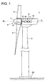
- FIG.1 shows an overall structure of the wind turbine generator in relation to the embodiment of the present invention.
- the wind turbine generator mainly includes a tower 2, a nacelle 3 mounted atop the tower 2, a rotor 4 rotated upon receiving the wind, a transmission increasing the rotation speed of the rotor 4 and a generator 12 generating electric power.
- the tower 2 is installed upright on a base 2A on the ground or offshore.
- the tower 2 extends vertically from a base part on the base side to a top part.
- the nacelle is supported rotatably.
- the rotor 4 is formed by the blade 5, the hub 6 to which the blade is attached and a main shaft 6 connected to the hub 6.
- the blade 5 is attached to the hub 6 rotatably in the direction of the pitch angle.
- FIG.1 shows the example with three blades. However, this is not limitative and it may be two blades or more than three blades.
- the hub 6 is attached to the nacelle 3.
- a plurality of the blades 5 are attached to the hub 6 radially around a rotation axis line, RL.
- a head capsule 7 is provided around the hub 6 to cover the hub 6. The head capsule 7 covers the hub 6 and rotates with the blade 5 and the hub 6 around the rotation axis line RL as a center axis.
- the main shaft 8 is arranged inside the nacelle 3 which is supported rotatably by the tower 2. Further, the main shaft 8 is supported on the nacelle side rotatably via a main shaft bearing. With the above structure, the wind acting on the blade 5 rotates the entire rotor 4. The rotation of the main shaft 8 is increased in the transmission 9 and the increased rotation speed is inputted to the generator 12 to generate electric power in the generator 12.
- the transmission 9 may be a mechanical transmission (gear type) or a hydraulic transmission.
- the mechanical transmission is illustrated in FIG.1 .
- the mechanical transmission 9 includes a step-up gear 10 for increasing the rotation speed of the main shaft 8.
- the transmission 9 may include a transmission mechanism 11 for transmitting a damping torque, such as a clutch, a torque converter and a continuously variable transmission (CVT).
- the hydraulic transmission (not shown) includes a hydraulic pump driven by the rotation of the main shaft 8, a hydraulic motor coupled to the generator 12 and a high pressure oil line and a low pressure oil line that are provided between the hydraulic pump and the hydraulic motor.
- a blade attaching method for the wind turbine generator in relation to the embodiment of the present invention is explained.
- the blades 5 are attached one by one to the hub 6 mounted to the nacelle 3.
- bolts 52 may be fitted to the blade root part 51 of the blade 5 beforehand as a preparation step.
- the bolts 52 are screwed into bolt holes 62 of a blade attaching part 61 of the hub 6 and used to fix the blade 5 to the hub 6.
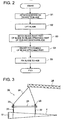
- FIG.3 is a schematic view showing the blade 5 in a suspended state.
- the suspension device 20 is preferably provided with ropes 22, 24 attached to the blade 5.
- the rope 22, 24, a fiber rope is preferably used as it is cheap to lower the cost of the suspension device 20 and is easy to transfer.
- a synthetic fiber rope made of nylon, polyester or the like is preferable.
- fiber ropes 22 are attached to two points of the blade 5 with a distance from each other in the longitudinal direction of the blade 5. These ropes 22 are then attached to a suspension jig 21 of a rod shape.
- the suspension jib 21 has a pair of shackles 23 at its both ends and another pair of fiber ropes 24 are attached to the shackles 23.
- the blade 5 is lifted by a crane 28 using the fiber ropes 24 so that the longitudinal direction of the blade 5 substantially coincides with the horizontal direction.
- the fiber ropes 24 may be suspended from the crane 28 at one suspension point as shown in FIG.3 , or at two suspension points. This, however, does not limit the invention.
- the blade 5 is lifted in such a state that the longitudinal direction of the blade 5 is maintained horizontally.
- this is not limitative and the blade 5 may be lifted in such a state that the longitudinal direction of the blade 5 is maintained vertically.
- a step S2 the blade 5 is lifted to a height of the hub 6 while being suspended.
- the blade attaching part 61 of the hub 6 (see FIG.5 ) and the blade root part 51 of the blade 5 (see FIG.4 ) are brought to face each other and the blade 5 is maintained there.
- the blade attaching part 61 of the hub 6 and the blade root part 51 of the blade 5 may be brought to a facing position by rotating the hub 6 around the rotation axis line, RL (see FIG.1 ) by means of the rotor drive mechanism (not shown).
- the pitch drive mechanism adjusts the pitch angle of the blade 5 by rotating the blade attaching part 61 of the hub 6.
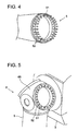
- the blade root part 51 of the blade 5 is provided with a plurality of bolts 52 (a second fastening member) circumferentially around a blade axis line.
- the blade attaching part 61 of the hub 6 is formed with a plurality of bolt holes 62 (a first fastening member) circumferentially around a center of a blade attaching plane. The first fastening member and the second fastening member are formed to fit into each other.
- the blade attaching part 61 is rotated by the pitch drive mechanism to a position where the bolt holes 62 of the blade attaching member 61 match the bolts 52 of the blade 5.
- the first fastening member is the bolt holes 62 and the second fastening member is the bolts 52.
- the first fastening member may be bolts while the second fastening member is bolt holes or any combination of the fastening members.
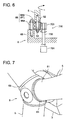
- FIG.6 one example of a sliding structure of the blade attaching part of the pitch drive mechanism and the blade attaching part is explained.
- a power system of the pitch drive mechanism is partially shown and a control system of the pitch drive mechanism is not shown. These systems are later described in details in reference to FIG.8 and FIG.9 .
- the blade attaching part 61 is attached rotatably to a hub body 65.
- the hub 6 is provided with the hub body 65 coupled to the blades 5, the blade attaching part 61 to which the blades 5 are attached and a bearing 66 which supports the blade attaching part 61 rotatably to the hub body 65.
- the bearing 66 is provided between the hub body 65 and the blade attaching part 61 and is formed by an outer ring 66A and an inner ring 66B.
- the outer ring is fixed to the hub body 65 and the inner ring 66B is fixed to the blade attaching part 61.
- the inner ring 66B constitutes the blade attaching part 61.
- a ball bearing is installed between the outer ring 66A and the outer ring 66B to reduce sliding resistance.
- the inner ring 66B is formed with internal teeth on an inner periphery.
- the pitch drive mechanism fundamentally adjusts the pitch angle of the blade 5 attached to the blade attaching part 61 by rotating the blade attaching part 61 of the hub 6. However, in the embodiment, the pitch drive mechanism rotates the blade attaching part 61 without the blade 5 attached thereto so as to adjust the pitch angle.
- FIG.6 shows a power system 700 of the pitch drive mechanism 700.
- the pitch drive mechanism 700 mainly includes a pinion gear 703, a shaft 705 and a motor 701.
- the motor 701 is fixed to the hub side.
- the pinion gear 703 is formed on the outer periphery with external teeth to mesh with internal teeth of the inner ring 66B.
- the pitch drive mechanism rotates in synchronization. This causes the external teeth of the pinion gear 703 to mesh with the internal teeth of the inner ring 66B, thereby rotating the inner ring 66B. In this manner, the pitch angle of the blade attaching part 61 is adjusted.
- a plurality of the power systems 700 may be provided along the inner periphery of the inner ring 66B.
- the pitch drive mechanism rotates the blade attaching part 61 by means of the gear meshing with the blade attaching part 61.
- the pitch drive mechanism may have any structure as long as it is capable of rotating the blade attaching part 61 directly or indirectly.
- a step S5 the bolts 52 of the blade root part 51 of the blade 5 are screwed into the bolt holes 62 of the blade attaching part of the hub 6 to fix the blade 5 to the hub 6.
- the bolts 52 are inserted through the bolt holes 62 and nuts are screwed to tips of the bolts 52 to fasten the bolts 52 and the bolt holes 62 together.
- the blade 5 is fixed to the hub 6 as shown in FIG.7 .
- the rotor 4 is rotated and then a second blade is attached.
- the second blade can be attached to the hub 6 by conducting the steps S1 to S5 described above. By repeating the steps S1 to S5 as many times as the number of the blades 5, all the blades 5 can be attached to the hub 6.
- the blade 5 is held in the step S3, the blade attaching part 61 on the hub side is rotated to the set angular position by the pitch drive mechanism in the step S4, and then the blade 5 is fixed to the hub 6 in the step S5.
- the pitch drive mechanism in the step S4 the pitch drive mechanism in the step S4
- the blade 5 is fixed to the hub 6 in the step S5.
- the blade 5 can be attached to the hub 6 without changing the orientation of the hub 5 by rotating the blade attaching part 61 on the hub side using the pitch drive mechanism.
- the blade attaching part 61 of the hub 6 is rotated to a position where the bolt holes 62 (the first fastening member) formed on the blade attaching part 61 of the hub 6 match the bolts 52 (the second fastening member) formed in the blade root part 51 of the blade 5.
- the bolt holes 62 of the blade attaching part 61 and the bolts 52 of the blade 5 are simply fastened together, thereby fixing the blade 5 to the hub 6 appropriately with absolutely no pitch angle adjustment performed on the blade side.
- the blade 5 is held in such a state that the blade 5 is suspended using the rope attached to the blade 5 so that the longitudinal direction of the blade 5 coincides with the horizontal or vertical direction.
- the position of the blade attaching part 61 in the rotation direction of the rotor 4 can be easily matched to the position of the blade root part 51 of the blade 5.
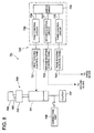
- FIG.8 shows a structure of the power system and the control system of the pitch drive mechanism in the case of using the electric motor.
- a pitch drive mechanism 7A includes the power system 700 using the electric motor 701 and the control system 720 which controls the power system 700.
- the power system 700 is provided in the hub 6 or the nacelle 3, and includes the electric motor 701, a reducer 702 and a pinion gear 703.
- the power is supplied from a grid power source 706 during the operation of the wind turbine generator 1 and, when the wind turbine generator 1 is stopped and the blade 5 is being attached, the power is supplied from a temporary power source 707.
- the temporary power source 707 may be installed temporary installed at the time of attaching the blade 5, or may be installed permanently.
- the electric motor 701 is powered by the power supplied from the temporary power source 707.
- the rotation of the electric motor 701 is reduced by the reducer 702 and then transmitted to the pinion gear via the shaft 705.
- the external teeth formed on the outer periphery of the pinion gear 703 mesh with the internal teeth of the inner ring 66B shown in FIG.6 , thereby rotating the blade attaching part 61 of the hub 6.
- the control system 720 includes a first existing control panel 721, a second existing control panel 722, a third existing control panel 723 and a temporary control panel 725.
- the first, second and third existing control panels 721, 722, 723 are arranged in the nacelle 3 or the hub 6.
- the first existing control panel 721 mainly controls the pitch angle of the first blade during the normal operation of the wind turbine generator 1. More specifically, the first existing control panel 721 controls the pitch angle of the first blade to extract the wind power energy efficiently and also controls the pitch angle of the first blade toward the feathering position to reduce the torque of the rotor by feathering the wind when the load on the wind turbine generator 1 increases rapidly.
- the second existing control panel 722 mainly controls the pitch angle of the second blade during the normal operation of the wind turbine generator 1.
- the third existing control panel 723 mainly controls the pitch angle of the third blade during the normal operation of the wind turbine generator 1.
- the second and third existing control panels 722, 723 have substantially the same configuration as the first existing control panels 721 and thus are not explained further in details.
- the temporary control panel 725 is arranged in the nacelle 3 or the hub 6.
- the temporary control panel 725 may be installed temporary installed during attaching of the blade 5 while the wind turbine generator 1 is stopped, or may be installed permanently.
- This temporary control panel 725 includes a first control circuit 726, a second control circuit 727, a third control circuit 728 and a switching circuit 729.
- the wind turbine generator 1 used in the embodiment includes three blades 5 and hence, there are the first to third existing control panels and the first to third control panels. However, the number of the existing control panels and control circuits is determined depending on the number of the blades.
- the first control circuit 726 mainly controls the pitch angle of the blade attaching part corresponding to the first blade when attaching of the blade 5 while the wind turbine generator 1 is stopped. More specifically, when attaching the first blade to the hub 6, the first control circuit controls the electric motor 702 to rotate the blade attaching part 61 by a set angle.
- the second control circuit 727 mainly controls the pitch angle of the blade attaching part corresponding to the second blade when attaching of the blade 5 while the wind turbine generator 1 is stopped.
- the third control circuit 728 mainly controls the pitch angle of the blade attaching part corresponding to the third blade when attaching of the blade 5 while the wind turbine generator 1 is stopped.
- the second and third existing control circuits 727, 728 have substantially the same configuration as the first existing control panels 726 and thus are not explained further in details.
- the switching circuit 729 switches to a corresponding one of the control circuits which corresponds to the electric motor for the blade to be attached.
- the method of attaching the blade 5 also includes the following steps before the step S4 of rotating the blade attaching part as described in FIG.2 . Those steps are the step of starting to supply the power to the electric motor 701 from the temporary power source 707 and the step of selecting, by use of the switching circuit 729, a corresponding control circuit of the first to third control circuits which corresponds to the blade 5 which is to be attached. Then, the blade attaching part 61 is rotated by controlling the electric motor 701 using the selected control circuit.
- the power is supplied to the electric motor for rotating the blade attaching part in the step of starting to supply the power before the step S4 of rotating the blade attaching part 61.
- the blade attaching part is rotated smoothly.
- the control circuits are sequentially switched by selecting a corresponding control circuit which corresponds to the electric motor 701 for the blade attaching part 61 to be rotated.
- FIG.9 shows a structure of the power system and the control system of the pitch drive mechanism in the case of using a hydraulic motor.
- a pitch drive mechanism 7B includes the power system 700 used during the normal operation of the wind turbine generator 1, another power system 710 used during attaching of the blade 5, and the control system 730 which controls the power systems 700, 710.
- the power system 700 is used during the normal operation of the wind turbine generator 1 and adjusts the pitch angle of the blade 5 using the electric motor 701.
- the power system 700 includes the electric motor 701, the reducer 702 and the pinion gear 703.
- the power is supplied from the grid power source to the electric motor 701 to actuate the electric motor 701.
- the rotation of the electric motor 701 is reduced by the reducer 702 and then transmitted to the pinion gear 703 via the shaft 705.
- the external teeth formed on the outer periphery of the pinion gear 703 mesh with the internal teeth of the inner ring 66B shown in FIG.6 , thereby rotating the blade attaching part 61 of the hub 6.
- the blade attached to the blade attaching part 61 rotates.
- the power system 710 is used during attaching of the blade 5, and adjusts the pitch angle of the blade attaching part 61 of the hub 6 by the use of the hydraulic motor 711.
- the power system 710 mainly includes the hydraulic motor 711, a hydraulic pump 712, a hydraulic line 713 and electromagnetic valves 715, 716.
- the hydraulic motor 711 rotates the shaft 708 by supplying the operating oil having been pressurized in the hydraulic pump 712.
- the rotation of the shaft 708 is inputted to the reducer 702 via a connection part 706 to reduce the rotation speed and then transmitted to the pinion gear 703 via the shaft 705.
- a clutch 707 is provided between the hydraulic motor 711 and the connection part 706. During the normal operation of the wind turbine generator 1, the clutch 707 is released to disconnect the hydraulic motor 711 from the reducer 702.
- the hydraulic line 713 includes a low pressure oil line 713A and a high pressure oil line 713B.
- the low pressure oil line 713A is provided between an outlet side of the hydraulic motor 711 and an inlet side of the hydraulic pump 712 to allow the low pressure operating oil (hereinafter, low pressure oil) having been discharged from the hydraulic motor 711 to flow therein.
- the high pressure oil line 713B is provided between an outlet side of the hydraulic pump 712 and an inlet side of the hydraulic motor 711 to allow the high pressure operating oil (hereinafter, high pressure oil) having been pressurized in the hydraulic pump 712 to flow therein.
- the electromagnetic valve 715 is provided in the low pressure oil line 713A and the electromagnetic valve 716 is provided in the high pressure oil line 713B to adjust the flow of the operating oil in each line.
- the hydraulic line 713 may include a branch line 713C which is connected to the high pressure oil line 713B.
- a high pressure accumulator 718 is provided to store the high pressure oil.
- an electromagnetic valve 719 is provided to adjust the flow of the operating oil.
- a low pressure accumulator 717 may be provided to store the low pressure oil.
- the control system 730 includes a first existing control panel 731, a second existing control panel 732, a third existing control panel 733 and a temporary control panel 735.
- the first, second and third existing control panels 731, 732, 733 are arranged in the nacelle 3 or the hub 6.
- the first existing control panel 731 mainly controls the pitch angle of the first blade during the normal operation of the wind turbine generator 1. More specifically, the first existing control panel 731 controls the pitch angle of the first blade to extract the wind power energy efficiently and also controls the pitch angle of the first blade toward the feathering position to reduce the torque of the rotor by feathering the wind when the load on the wind turbine generator 1 increases rapidly.
- the second existing control panel 732 mainly controls the pitch angle of the second blade during the normal operation of the wind turbine generator 1.
- the third existing control panel 733 mainly controls the pitch angle of the third blade during the normal operation of the wind turbine generator 1.
- the second and third existing control panels 732, 733 have substantially the same configuration as the first existing control panels 731 and thus are not explained further in details.
- the temporary control panel 735 is arranged in the nacelle 3 or the hub 6.
- the temporary control panel 735 may be installed temporary installed during attaching of the blade 5 while the wind turbine generator 1 is stopped, or may be installed permanently.
- This temporary control panel 725 includes a first control circuit 736, a second control circuit 737, a third control circuit 738 and a switching circuit 739.
- the wind turbine generator 1 used in the embodiment includes three blades 5 and hence, there are the first to third existing control panels and the first to third control panels. However, the number of the existing control panels and control circuits is determined depending on the number of the blades.
- the first control circuit 736 mainly controls the pitch angle of the blade attaching part corresponding to the first blade when attaching of the blade 5 while the wind turbine generator 1 is stopped. More specifically, when attaching the first blade to the hub 6, the electromagnetic valves 715, 716 are opened to actuate the hydraulic motor 711 and then the blade attaching part 61 is rotated by the set angle.
- the second control circuit 737 mainly controls the pitch angle of the blade attaching part corresponding to the second blade when attaching of the blade 5 while the wind turbine generator 1 is stopped.
- the third control circuit 738 mainly controls the pitch angle of the blade attaching part corresponding to the third blade when attaching of the blade 5 while the wind turbine generator 1 is stopped.
- the second and third existing control circuits 737, 738 have substantially the same configuration as the first existing control panels 736 and thus are not explained further in details.
- the switching circuit 739 switches to a corresponding one of the control circuits which corresponds to the electromagnetic valves 715, 716 of the hydraulic circuit for the blade to be attached.
- the method of attaching the blade 5 also includes the following step before the step S4 of rotating the blade attaching part as described in FIG.2 .
- the step is the step of selecting a corresponding one using the switching circuit 739 from the first to third control circuits, which corresponds to the blade which is to be attached. Using the selected control circuit, the electromagnetic valves 715, 716 are controlled to open so as to activate the hydraulic pump 711, thereby rotating the blade attaching part 61.
- a corresponding control circuit which corresponds to the electromagnetic valves 715, 716 of the blade attaching part 716 which is to be rotated, is selected and switched to in a sequential manner.
- t is possible to perform the blade attaching operation continuously.
- the blade attaching method may also include the step of storing high pressure operating oil having been pressurized by the hydraulic pump 712 in the high pressure accumulator 718, the hydraulic pump 712 being driven by power supplied from the grid side during operation of the wind turbine generator 1.
- the high pressure oil stored in the high pressure accumulator 718 is supplied to the hydraulic motor 711.
- the pitch drive mechanism 7B can be still activated while minimizing the power used for attaching the blade 5 while the wind turbine generator 1 is stopped.
- the blade attaching part 61 on the hub side is rotated to the set angular position using the pitch drive mechanism 7A, 7B and then fixed to the hub 6.
- the pitch drive mechanism 7A, 7B is rotated to the set angular position using the pitch drive mechanism 7A, 7B and then fixed to the hub 6.
- the blade 5 can be attached to the hub 6 without changing the orientation, by rotating the blade attaching part 61 on the hub side using the pitch drive mechanism 7A, 7B.
- the wind turbine generator 1 is described as one particular example of the power generating apparatus of renewable energy type.
- the present invention is also applicable to other types of power generating apparatuses of renewable energy type.
- the present invention is applicable to a power generating apparatus which generates power from tidal current, ocean current or river current and whose tower extends vertically downward in the ocean or water from the base part to the tip part of the tower and whose main shaft rotates upon receiving tidal current, ocean current or river current on the blade.
Landscapes
- Engineering & Computer Science (AREA)
- Chemical & Material Sciences (AREA)
- Combustion & Propulsion (AREA)
- Mechanical Engineering (AREA)
- General Engineering & Computer Science (AREA)
- Life Sciences & Earth Sciences (AREA)
- Sustainable Development (AREA)
- Sustainable Energy (AREA)
- General Life Sciences & Earth Sciences (AREA)
- Oceanography (AREA)
- Power Engineering (AREA)
- Wind Motors (AREA)
Abstract
Description
- The present invention relates to a blade attaching method a power generating apparatus of renewable energy type, which transmits rotation energy of a blade rotated by renewable energy to a generator to generate power. The power generating apparatus of renewable energy type generates power from renewable energy such as wind, tidal current, ocean current and river current and, the power generating apparatus of renewable energy type, for instance, includes a wind turbine generator, a tidal generator, an ocean current generator, a river current generator or the like.
- In recent years, from a perspective of preserving the environment, it is becoming popular to use a power generating apparatus of renewable energy type such as a wind turbine generator utilizing wind power and renewable energy type turbine generator such as a tidal current generator utilizing tidal. In the power generating apparatus of renewable energy type, a motion energy of the wind, the tidal current, the ocean current or the river current rotates the blade and the rotation energy is inputted to the generator via the hub and the main shaft to generate power into electric power by the generator.
- For instance, the wind turbine generator is provided with a tower, a nacelle installed atop the tower, a main shaft rotatably attached to the nacelle, a hub connected to the main shaft, blades attached radially to the hub. In this wind turbine generator, the rotation energy of the blade rotated by the wind power is inputted to the generator via the hub and the main shaft to generate electrical power. Further, the wind turbine generator is further provided with a pitch angle control mechanism for controlling the pitch angle of the blade to efficiently extract the wind power energy. The pitch angle control mechanism is also used to reduce the torque of the rotor by changing the pitch angle of the blade toward a feathering position to feather the wind when the load acting on the wind turbine generator increases rapidly.
- In such wind turbine generator, when attaching the blade, first the blade is lifted to a height of the nacelle and then a blade root part of the blade and a blade attaching part of the hub are fastened together, thereby attaching the blade to the hub. In such a case that there is enough flat land around the location of the wind turbine generator, the blade may be attached to the hub before mounting the hub to the nacelle.
- As related technique, disclosed in
Patent Literature 1 is a blade attaching method in which the blade is maintained horizontally when the blade is lifted to the hub. According to the method, an orientation of the blade is maintained substantially the same by use of control wires connecting the blade to a winch. Further, disclosed inPatent Literature 2 is another blade attaching method in which the blade is clamped horizontally by a clamping device and lifted to the hub and then the blade is attached to the hub. Further, disclosed inPatent Literature 3 is yet another blade attaching method in which, when the blade is attached to the hub, the pitch angle of the blade is adjusted. According to this method, the blade is held by a holding device including a frame and a seat. The orientation of the blade is adjusted by rotating the holding device in a direction of the pitch angle. -
- [PTL 1]
-
EP1925582A - [PTL 2]
-
EP1507975A - [PTL 3]
-
EP2084098A - As described above, a power generating apparatus of renewable energy type has blades whose pitch angle is adjustable. Thus, when attaching the blade, a connection part of the blade side and the connection part of the hub side must be matched.
Therefore, in the conventional blade attaching method disclosed inPatent Literature
In the method disclosed inPatent Literature 3, the holding device with the blade held therein is rotated in the direction of the pitch angle to adjust the orientation of the blade. However, changing the orientation of the blade in midair is extremely difficult and it requires a high level of skill to properly adjust the orientation of the blade. - In view of the issues above, it is an object of the present invention is to provide a blade attaching method for a power generating apparatus of renewable energy type, which is capable of attaching the blade to the hub easily without using a large-scale equipment for attaching the blade.
- The present invention provides a blade attaching method for a power generating apparatus of renewable energy type which includes a blade, a hub having a blade attaching part to which the blade is attached and a bearing which supports the blade attaching part rotatably, a generator to which a torque is inputted from a side of a rotor including the blade and the hub, and a pitch drive mechanism which adjusts a pitch angle of the blade by rotating the blade attaching part and the method may include, but is not limited to, the steps of:
- holding the blade in such a manner that the blade attaching part of the hub faces a blade root part of the blade;
- rotating the blade attaching part to a set angular position by the pitch drive mechanism in such a state that the blade is held; and
- after rotating the blade attaching part to the set angular position, fixing the blade to the hub.
- According to the blade attaching method for the power generating apparatus of renewable energy type, the blade attaching part is rotated to the set angular position by the pitch drive mechanism in such a state that the blade is held and then the blade is fixed to the hub. Thus, it is no longer needed to adjust the orientation of the blade to match the blade attaching part on the hub side and the blade can be attached to the hub easily without a large-scale equipment for attaching the blade. Further, in the case of lifting the blade to the hub, even when the orientation of the blade changes due to a strong wind or the like, the blade can be attached to the hub without changing its orientation by rotating the blade attaching part on the hub side using the pitch drive mechanism. Further, in the process of facing the blade attaching part of the hub to the blade root part of the blade, the hub may be already attached to the nacelle or may be still placed on the ground and not attached to the nacelle yet.
- In the above blade attaching method for the power generating apparatus of renewable energy type,
the blade attaching part of the hub may be formed with a first fastening member, and the blade root part of the blade is formed with a second fastening member to be fitted to the first fastening membert,
in the rotating step, the blade attaching part may be rotated to a position where the first fastening member matches the second fastening member, and
in the fixing step, the blade may be fixed to the hub by means of the first fastening member and the second fastening member. - In this manner, in the step of rotating the blade attaching part, the blade attaching part of the hub is rotated to the position where the first fastening member formed on the blade attaching part of the hub matches the second fastening member formed on the blade root part of the blade. Thus, in the step of fixing the blade to the hub, the first and second fastening members are simply fastened together, thereby fixing the blade to the hub appropriately with absolutely no pitch angle adjustment performed on the blade side. The fitting of the fastening members includes screwing the fastening members together.
- In the above blade attaching method for the power generating apparatus of renewable energy type,
in the holding step, the blade may be held in such a state that the blade is suspended using a rope attached to the blade so that a longitudinal direction of the blade coincides with a horizontal or vertical direction.
In this manner, in the holding step, the blade is held in such a state that the blade is suspended using the rope so that the longitudinal direction of the blade coincides with the horizontal or vertical direction. Thus, it is easy to match the position of the blade attaching part of the hub in the rotation direction of the rotor to the position of the blade root part of the blade. - In such case, the rope is preferably a fiber rope.
Herein, ropes made from synthetic fiber such as nylon and polyester may be used as the fiber rope.
In this manner, using of the fiber rope as the rope lowers the cost of the device for lifting the blade and also facilitates transferring of the device. - In the above blade attaching method for the power generating apparatus of renewable energy type,
the pitch drive mechanism may include, but is not limited to, an electric motor which rotates the blade attaching part and a power source which supplies power to the electric motor, and
the blade attaching method may also include the step of starting to supply the power to the electric motor, before the rotating step.
In this manner, by driving the pitch drive mechanism using the electric motor, the maintainability of the wind turbine generator is improved.
Further, when attaching the blade, the power generating apparatus of renewable energy type is normally in a shutdown state and thus the power supply is stopped as well. Thus, before the step of rotating the blade attaching part, the power is supplied to the electric motor in the step of starting to supply the power, so as to rotate the blade attaching part smoothly. The electric motor may be installed permanently in the power generating apparatus of renewable energy type or may be installed temporary when attaching the blade. - In such case, the power generating apparatus of renewable energy type may include a plurality of the blades,
a plurality of the electric motors may be provided for the plurality of the blades, respectively,
a control panel including a plurality of control circuits which control the plurality of the electric motors, respectively, and
the blade attaching method may further include the step of: - before the rotating step, selecting a corresponding one of the control circuits which corresponds to the electric motor for the blade attaching part which is to be rotated.
- In the above blade attaching method for the power generating apparatus,
the pitch drive mechanism may include, but is not limited to: - a hydraulic motor which rotates the blade attaching part;
- a hydraulic pump which pressurizes operating oil to be supplied to the hydraulic motor;
- a hydraulic line through which the operating oil circulates between the hydraulic motor and the hydraulic pump; and
- a valve which is provided in the hydraulic line and which controls supply of the operating oil to the hydraulic motor, and
- before the rotating step, the method my further include the step of:
- starting the supply of the operating oil to the hydraulic motor by opening the valve.
- In such case, the above power generating apparatus of renewable energy type may include a plurality of the blades,
the hydraulic motor and the valve may be provided for each of the blades,
a control panel including a plurality of control circuits may be provided, each of the control circuits controlling an opening of the valve, and
the blade attaching method may further include the step of: - before the rotating step, selecting a corresponding one of the control circuits which corresponds to the valve for the blade attaching part which is to be rotated.
- Further, in the above case, in the above power generating apparatus of renewable energy type,
an accumulator may be connected to the hydraulic line, the accumulator storing the operating oil having been pressurized by the hydraulic pump,
the blade attaching method may further include the step of: - before the holding step, storing high pressure operating oil having been pressurized by the hydraulic pump in the accumulator, the hydraulic pump being driven by power supplied from a grid side during operation of the power generating apparatus of renewable energy type, and
- in the rotating step, the high pressure operating oil stored in the accumulator may be supplied to the hydraulic motor.
- Furthermore, the above power generating apparatus of renewable energy type may be a wind turbine generator in which the rotor is rotated by the wind in a form of the renewable energy and the torque is inputted from the rotor side to the generator to generate power in the generator.
- According to the present invention, in such a state that the blade is held, the blade attaching part on the hub side is rotated to the set angular position using the pitch drive mechanism and then fixed to the hub. Thus, it is no longer needed to adjust the orientation of the blade to match the blade attaching part on the hub side and the blade can be attached to the hub easily without a large-scale equipment for attaching the blade. Further, in the case of lifting the blade to the hub, even when the orientation of the blade changes due to a strong wind or the like, the blade can be attached to the hub without changing its orientation, by rotating the blade attaching part on the hub side using the pitch drive mechanism.
-
- [
FIG.1] FIG.1 shows an overall structure of a wind turbine generator in relation to an embodiment of the present invention. - [
FIG.2] FIG.2 is a flow chart showing a blade attaching method for the wind turbine generator in relation to an embodiment of the present invention. - [
FIG.3] FIG.3 is a schematic view showing a blade in a lifted state. - [
FIG.4] FIG.4 is an oblique perspective view of a blade root part of the blade. - [
FIG.5] FIG.5 is an oblique perspective view of a hub. - [
FIG.6] FIG.6 is a schematic view showing an example of a sliding structure of a pitch drive mechanism and a blade attaching part. - [
FIG.7] FIG.7 is an oblique perspective view of the blade fixed to the hub. - [
FIG.8] FIG.8 shows a structure of a power system and a control system of the pitch drive mechanism in the case of using an electric motor. - [
FIG.9] FIG.9 shows a structure of the power system and the control system of the pitch drive mechanism in the case of using a hydraulic motor. - A preferred embodiment of the present invention will now be described in detail with reference to the accompanying drawings. It is intended, however, that unless particularly specified, dimensions, materials, shape, its relative positions and the like shall be interpreted as illustrative only and not limitative of the scope of the present invention.
- In an embodiment of the present invention, a wind turbine generator is used as an example of the power generating apparatus of renewable energy type.
FIG.1 shows an overall structure of the wind turbine generator in relation to the embodiment of the present invention.
As shown inFIG.1 , the wind turbine generator mainly includes atower 2, anacelle 3 mounted atop thetower 2, arotor 4 rotated upon receiving the wind, a transmission increasing the rotation speed of therotor 4 and agenerator 12 generating electric power. - The
tower 2 is installed upright on abase 2A on the ground or offshore. Thetower 2 extends vertically from a base part on the base side to a top part. At the top part of thetower 2, the nacelle is supported rotatably. - The
rotor 4 is formed by theblade 5, thehub 6 to which the blade is attached and amain shaft 6 connected to thehub 6.
Theblade 5 is attached to thehub 6 rotatably in the direction of the pitch angle.FIG.1 shows the example with three blades. However, this is not limitative and it may be two blades or more than three blades.
Thehub 6 is attached to thenacelle 3. A plurality of theblades 5 are attached to thehub 6 radially around a rotation axis line, RL. Ahead capsule 7 is provided around thehub 6 to cover thehub 6.
Thehead capsule 7 covers thehub 6 and rotates with theblade 5 and thehub 6 around the rotation axis line RL as a center axis. - The
main shaft 8 is arranged inside thenacelle 3 which is supported rotatably by thetower 2. Further, themain shaft 8 is supported on the nacelle side rotatably via a main shaft bearing.
With the above structure, the wind acting on theblade 5 rotates theentire rotor 4. The rotation of themain shaft 8 is increased in thetransmission 9 and the increased rotation speed is inputted to thegenerator 12 to generate electric power in thegenerator 12. - The
transmission 9 may be a mechanical transmission (gear type) or a hydraulic transmission. As an example, the mechanical transmission is illustrated inFIG.1 . More specifically, themechanical transmission 9 includes a step-upgear 10 for increasing the rotation speed of themain shaft 8. Further, thetransmission 9 may include atransmission mechanism 11 for transmitting a damping torque, such as a clutch, a torque converter and a continuously variable transmission (CVT). In contrast, the hydraulic transmission (not shown) includes a hydraulic pump driven by the rotation of themain shaft 8, a hydraulic motor coupled to thegenerator 12 and a high pressure oil line and a low pressure oil line that are provided between the hydraulic pump and the hydraulic motor. - In reference to the flow chart of
FIG.2 , a blade attaching method for the wind turbine generator in relation to the embodiment of the present invention is explained. In the method described here, theblades 5 are attached one by one to thehub 6 mounted to thenacelle 3.
In this method, as shown inFIG.4 ,bolts 52 may be fitted to theblade root part 51 of theblade 5 beforehand as a preparation step. Thebolts 52 are screwed into bolt holes 62 of ablade attaching part 61 of thehub 6 and used to fix theblade 5 to thehub 6. - First, in a step S1, a
suspension device 20 is attached to theblade 5.FIG.3 is a schematic view showing theblade 5 in a suspended state. As shown inFIG.3 , thesuspension device 20 is preferably provided withropes blade 5. As therope suspension device 20 and is easy to transfer. Particularly, from a perspective of strength, a synthetic fiber rope made of nylon, polyester or the like is preferable. - More specifically,
fiber ropes 22 are attached to two points of theblade 5 with a distance from each other in the longitudinal direction of theblade 5. Theseropes 22 are then attached to asuspension jig 21 of a rod shape. Thesuspension jib 21 has a pair ofshackles 23 at its both ends and another pair offiber ropes 24 are attached to theshackles 23. Then, theblade 5 is lifted by acrane 28 using thefiber ropes 24 so that the longitudinal direction of theblade 5 substantially coincides with the horizontal direction. In this process, thefiber ropes 24 may be suspended from thecrane 28 at one suspension point as shown inFIG.3 , or at two suspension points. This, however, does not limit the invention. In the example shown inFIG.3 , theblade 5 is lifted in such a state that the longitudinal direction of theblade 5 is maintained horizontally. However, this is not limitative and theblade 5 may be lifted in such a state that the longitudinal direction of theblade 5 is maintained vertically. - In a step S2, the
blade 5 is lifted to a height of thehub 6 while being suspended.
Next, in a step S3, theblade attaching part 61 of the hub 6 (seeFIG.5 ) and theblade root part 51 of the blade 5 (seeFIG.4 ) are brought to face each other and theblade 5 is maintained there. In this process, theblade attaching part 61 of thehub 6 and theblade root part 51 of theblade 5 may be brought to a facing position by rotating thehub 6 around the rotation axis line, RL (seeFIG.1 ) by means of the rotor drive mechanism (not shown). - Next, in a step S4, the pitch drive mechanism adjusts the pitch angle of the
blade 5 by rotating theblade attaching part 61 of thehub 6.
As shown inFIG.4 , theblade root part 51 of theblade 5 is provided with a plurality of bolts 52 (a second fastening member) circumferentially around a blade axis line. In a manner similar to this, as shown inFIG.5 , theblade attaching part 61 of thehub 6 is formed with a plurality of bolt holes 62 (a first fastening member) circumferentially around a center of a blade attaching plane. The first fastening member and the second fastening member are formed to fit into each other. Therefore, in the step S4, theblade attaching part 61 is rotated by the pitch drive mechanism to a position where the bolt holes 62 of theblade attaching member 61 match thebolts 52 of theblade 5. In the examples shown inFIG.4 and FIG.5 , the first fastening member is the bolt holes 62 and the second fastening member is thebolts 52. However, this is not limitative and the first fastening member may be bolts while the second fastening member is bolt holes or any combination of the fastening members. - In reference to
FIG.6 , one example of a sliding structure of the blade attaching part of the pitch drive mechanism and the blade attaching part is explained. InFIG.6 , a power system of the pitch drive mechanism is partially shown and a control system of the pitch drive mechanism is not shown. These systems are later described in details in reference toFIG.8 andFIG.9 .
As shown inFIG.6 , theblade attaching part 61 is attached rotatably to ahub body 65. Thehub 6 is provided with thehub body 65 coupled to theblades 5, theblade attaching part 61 to which theblades 5 are attached and abearing 66 which supports theblade attaching part 61 rotatably to thehub body 65.
Thebearing 66 is provided between thehub body 65 and theblade attaching part 61 and is formed by anouter ring 66A and aninner ring 66B. The outer ring is fixed to thehub body 65 and theinner ring 66B is fixed to theblade attaching part 61. In the embodiment, theinner ring 66B constitutes theblade attaching part 61. Between theouter ring 66A and theouter ring 66B, a ball bearing is installed to reduce sliding resistance. Further, theinner ring 66B is formed with internal teeth on an inner periphery. - The pitch drive mechanism fundamentally adjusts the pitch angle of the
blade 5 attached to theblade attaching part 61 by rotating theblade attaching part 61 of thehub 6. However, in the embodiment, the pitch drive mechanism rotates theblade attaching part 61 without theblade 5 attached thereto so as to adjust the pitch angle.FIG.6 shows apower system 700 of thepitch drive mechanism 700. Thepitch drive mechanism 700 mainly includes apinion gear 703, ashaft 705 and amotor 701. Themotor 701 is fixed to the hub side. Thepinion gear 703 is formed on the outer periphery with external teeth to mesh with internal teeth of theinner ring 66B. In thepower system 700 of the pitch drive mechanism, when theshaft 705 is rotated by themotor 701, thepinion gear 703 coupled to theshaft 705 rotates in synchronization. This causes the external teeth of thepinion gear 703 to mesh with the internal teeth of theinner ring 66B, thereby rotating theinner ring 66B. In this manner, the pitch angle of theblade attaching part 61 is adjusted. A plurality of thepower systems 700 may be provided along the inner periphery of theinner ring 66B.
In the above description, the pitch drive mechanism rotates theblade attaching part 61 by means of the gear meshing with theblade attaching part 61. The pitch drive mechanism may have any structure as long as it is capable of rotating theblade attaching part 61 directly or indirectly. - Then, in a step S5, the
bolts 52 of theblade root part 51 of theblade 5 are screwed into the bolt holes 62 of the blade attaching part of thehub 6 to fix theblade 5 to thehub 6. In this process, preferably, thebolts 52 are inserted through the bolt holes 62 and nuts are screwed to tips of thebolts 52 to fasten thebolts 52 and the bolt holes 62 together. In this manner, theblade 5 is fixed to thehub 6 as shown inFIG.7 .
In such a case that a plurality ofblades 5 are provided, after a first blade is attached to thehub 6, therotor 4 is rotated and then a second blade is attached. As for the second blade, the second blade can be attached to thehub 6 by conducting the steps S1 to S5 described above. By repeating the steps S1 to S5 as many times as the number of theblades 5, all theblades 5 can be attached to thehub 6. - In this manner, the
blade 5 is held in the step S3, theblade attaching part 61 on the hub side is rotated to the set angular position by the pitch drive mechanism in the step S4, and then theblade 5 is fixed to thehub 6 in the step S5. Thus, it is no longer necessary to adjust the orientation of theblade 5 to match theblade attaching part 61 on the hub side or to provide a large-scale device for attaching the blade, and it is now possible to attach theblade 5 to thehub 6 easily. In such a case that theblade 5 is lifted and attached to thehub 8, even when the orientation of theblade 5 is changed due to a strong wind or the like, theblade 5 can be attached to thehub 6 without changing the orientation of thehub 5 by rotating theblade attaching part 61 on the hub side using the pitch drive mechanism. - Further, in the step S4 of rotating the
blade attaching part 61, theblade attaching part 61 of thehub 6 is rotated to a position where the bolt holes 62 (the first fastening member) formed on theblade attaching part 61 of thehub 6 match the bolts 52 (the second fastening member) formed in theblade root part 51 of theblade 5. Thus, in the step S5 of fixing theblade 5 to thehub 6, the bolt holes 62 of theblade attaching part 61 and thebolts 52 of theblade 5 are simply fastened together, thereby fixing theblade 5 to thehub 6 appropriately with absolutely no pitch angle adjustment performed on the blade side. - Furthermore, in the step S3 of holding the
blade 5, theblade 5 is held in such a state that theblade 5 is suspended using the rope attached to theblade 5 so that the longitudinal direction of theblade 5 coincides with the horizontal or vertical direction. Thus, the position of theblade attaching part 61 in the rotation direction of therotor 4 can be easily matched to the position of theblade root part 51 of theblade 5. - In reference to
FIG.8 andFIG.9 , the power system and the control system of the pitch drive mechanism is explained below. -
FIG.8 shows a structure of the power system and the control system of the pitch drive mechanism in the case of using the electric motor.
As shown inFIG.8 , apitch drive mechanism 7A includes thepower system 700 using theelectric motor 701 and thecontrol system 720 which controls thepower system 700. - The
power system 700 is provided in thehub 6 or thenacelle 3, and includes theelectric motor 701, areducer 702 and apinion gear 703. To theelectric motor 701, the power is supplied from agrid power source 706 during the operation of thewind turbine generator 1 and, when thewind turbine generator 1 is stopped and theblade 5 is being attached, the power is supplied from atemporary power source 707. Thetemporary power source 707 may be installed temporary installed at the time of attaching theblade 5, or may be installed permanently.
When theblade 5 is attached to thehub 6, theelectric motor 701 is powered by the power supplied from thetemporary power source 707. The rotation of theelectric motor 701 is reduced by thereducer 702 and then transmitted to the pinion gear via theshaft 705. Then, the external teeth formed on the outer periphery of thepinion gear 703 mesh with the internal teeth of theinner ring 66B shown inFIG.6 , thereby rotating theblade attaching part 61 of thehub 6. - The
control system 720 includes a first existingcontrol panel 721, a second existingcontrol panel 722, a third existingcontrol panel 723 and atemporary control panel 725.
The first, second and third existingcontrol panels nacelle 3 or thehub 6.
The first existingcontrol panel 721 mainly controls the pitch angle of the first blade during the normal operation of thewind turbine generator 1. More specifically, the first existingcontrol panel 721 controls the pitch angle of the first blade to extract the wind power energy efficiently and also controls the pitch angle of the first blade toward the feathering position to reduce the torque of the rotor by feathering the wind when the load on thewind turbine generator 1 increases rapidly. - The second existing
control panel 722 mainly controls the pitch angle of the second blade during the normal operation of thewind turbine generator 1.
The third existingcontrol panel 723 mainly controls the pitch angle of the third blade during the normal operation of thewind turbine generator 1.
The second and third existingcontrol panels control panels 721 and thus are not explained further in details. - The
temporary control panel 725 is arranged in thenacelle 3 or thehub 6. Thetemporary control panel 725 may be installed temporary installed during attaching of theblade 5 while thewind turbine generator 1 is stopped, or may be installed permanently. Thistemporary control panel 725 includes afirst control circuit 726, asecond control circuit 727, athird control circuit 728 and aswitching circuit 729.
As one example, thewind turbine generator 1 used in the embodiment includes threeblades 5 and hence, there are the first to third existing control panels and the first to third control panels. However, the number of the existing control panels and control circuits is determined depending on the number of the blades. - The
first control circuit 726 mainly controls the pitch angle of the blade attaching part corresponding to the first blade when attaching of theblade 5 while thewind turbine generator 1 is stopped. More specifically, when attaching the first blade to thehub 6, the first control circuit controls theelectric motor 702 to rotate theblade attaching part 61 by a set angle.
Thesecond control circuit 727 mainly controls the pitch angle of the blade attaching part corresponding to the second blade when attaching of theblade 5 while thewind turbine generator 1 is stopped
Thethird control circuit 728 mainly controls the pitch angle of the blade attaching part corresponding to the third blade when attaching of theblade 5 while thewind turbine generator 1 is stopped.
The second and third existingcontrol circuits control panels 726 and thus are not explained further in details.
Theswitching circuit 729 switches to a corresponding one of the control circuits which corresponds to the electric motor for the blade to be attached. - In the
wind turbine generator 1 having thepower system 700 and thecontrol system 720 described above, the method of attaching theblade 5 also includes the following steps before the step S4 of rotating the blade attaching part as described inFIG.2 . Those steps are the step of starting to supply the power to theelectric motor 701 from thetemporary power source 707 and the step of selecting, by use of theswitching circuit 729, a corresponding control circuit of the first to third control circuits which corresponds to theblade 5 which is to be attached. Then, theblade attaching part 61 is rotated by controlling theelectric motor 701 using the selected control circuit. - In this manner, the power is supplied to the electric motor for rotating the blade attaching part in the step of starting to supply the power before the step S4 of rotating the
blade attaching part 61. Thus, the blade attaching part is rotated smoothly. Further, the control circuits are sequentially switched by selecting a corresponding control circuit which corresponds to theelectric motor 701 for theblade attaching part 61 to be rotated. Thus, it is possible to conduct the blade attaching process in a continuous manner. -
FIG.9 shows a structure of the power system and the control system of the pitch drive mechanism in the case of using a hydraulic motor.
As shown inFIG.9 , apitch drive mechanism 7B includes thepower system 700 used during the normal operation of thewind turbine generator 1, anotherpower system 710 used during attaching of theblade 5, and thecontrol system 730 which controls thepower systems - The
power system 700 is used during the normal operation of thewind turbine generator 1 and adjusts the pitch angle of theblade 5 using theelectric motor 701. Thepower system 700 includes theelectric motor 701, thereducer 702 and thepinion gear 703. The power is supplied from the grid power source to theelectric motor 701 to actuate theelectric motor 701. The rotation of theelectric motor 701 is reduced by thereducer 702 and then transmitted to thepinion gear 703 via theshaft 705. Then, the external teeth formed on the outer periphery of thepinion gear 703 mesh with the internal teeth of theinner ring 66B shown inFIG.6 , thereby rotating theblade attaching part 61 of thehub 6. In response to the rotation of theblade attaching part 61, the blade attached to theblade attaching part 61 rotates. - The
power system 710 is used during attaching of theblade 5, and adjusts the pitch angle of theblade attaching part 61 of thehub 6 by the use of thehydraulic motor 711. Thepower system 710 mainly includes thehydraulic motor 711, ahydraulic pump 712, ahydraulic line 713 andelectromagnetic valves
Thehydraulic motor 711 rotates theshaft 708 by supplying the operating oil having been pressurized in thehydraulic pump 712. The rotation of theshaft 708 is inputted to thereducer 702 via aconnection part 706 to reduce the rotation speed and then transmitted to thepinion gear 703 via theshaft 705. Then, the external teeth formed on the outer periphery of thepinion gear 703 mesh with the internal teeth of theinner ring 66B shown inFIG.6 , thereby rotating theblade attaching part 61 of thehub 6. Further, a clutch During the normal operation of thewind turbine generator 1, a clutch 707 is provided between thehydraulic motor 711 and theconnection part 706. During the normal operation of thewind turbine generator 1, the clutch 707 is released to disconnect thehydraulic motor 711 from thereducer 702. - The
hydraulic line 713 includes a lowpressure oil line 713A and a highpressure oil line 713B. The lowpressure oil line 713A is provided between an outlet side of thehydraulic motor 711 and an inlet side of thehydraulic pump 712 to allow the low pressure operating oil (hereinafter, low pressure oil) having been discharged from thehydraulic motor 711 to flow therein. The highpressure oil line 713B is provided between an outlet side of thehydraulic pump 712 and an inlet side of thehydraulic motor 711 to allow the high pressure operating oil (hereinafter, high pressure oil) having been pressurized in thehydraulic pump 712 to flow therein. Further, theelectromagnetic valve 715 is provided in the lowpressure oil line 713A and theelectromagnetic valve 716 is provided in the highpressure oil line 713B to adjust the flow of the operating oil in each line.
Thehydraulic line 713 may include abranch line 713C which is connected to the highpressure oil line 713B. In thebranch line 713C, preferably ahigh pressure accumulator 718 is provided to store the high pressure oil. In thebranch line 713C, anelectromagnetic valve 719 is provided to adjust the flow of the operating oil.
Furthermore, in the lowpressure oil line 713A, alow pressure accumulator 717 may be provided to store the low pressure oil. - The
control system 730 includes a first existingcontrol panel 731, a second existingcontrol panel 732, a third existingcontrol panel 733 and atemporary control panel 735.
The first, second and third existingcontrol panels nacelle 3 or thehub 6.
The first existingcontrol panel 731 mainly controls the pitch angle of the first blade during the normal operation of thewind turbine generator 1. More specifically, the first existingcontrol panel 731 controls the pitch angle of the first blade to extract the wind power energy efficiently and also controls the pitch angle of the first blade toward the feathering position to reduce the torque of the rotor by feathering the wind when the load on thewind turbine generator 1 increases rapidly. - The second existing
control panel 732 mainly controls the pitch angle of the second blade during the normal operation of thewind turbine generator 1.
The third existingcontrol panel 733 mainly controls the pitch angle of the third blade during the normal operation of thewind turbine generator 1.
The second and third existingcontrol panels control panels 731 and thus are not explained further in details. - The
temporary control panel 735 is arranged in thenacelle 3 or thehub 6. Thetemporary control panel 735 may be installed temporary installed during attaching of theblade 5 while thewind turbine generator 1 is stopped, or may be installed permanently. Thistemporary control panel 725 includes afirst control circuit 736, asecond control circuit 737, athird control circuit 738 and aswitching circuit 739.
As one example, thewind turbine generator 1 used in the embodiment includes threeblades 5 and hence, there are the first to third existing control panels and the first to third control panels. However, the number of the existing control panels and control circuits is determined depending on the number of the blades. - The
first control circuit 736 mainly controls the pitch angle of the blade attaching part corresponding to the first blade when attaching of theblade 5 while thewind turbine generator 1 is stopped. More specifically, when attaching the first blade to thehub 6, theelectromagnetic valves hydraulic motor 711 and then theblade attaching part 61 is rotated by the set angle.
Thesecond control circuit 737 mainly controls the pitch angle of the blade attaching part corresponding to the second blade when attaching of theblade 5 while thewind turbine generator 1 is stopped
Thethird control circuit 738 mainly controls the pitch angle of the blade attaching part corresponding to the third blade when attaching of theblade 5 while thewind turbine generator 1 is stopped.
The second and third existingcontrol circuits control panels 736 and thus are not explained further in details.
Theswitching circuit 739 switches to a corresponding one of the control circuits which corresponds to theelectromagnetic valves - In the
wind turbine generator 1 having thepower system 710 and thecontrol system 730 described above, the method of attaching theblade 5 also includes the following step before the step S4 of rotating the blade attaching part as described inFIG.2 . The step is the step of selecting a corresponding one using theswitching circuit 739 from the first to third control circuits, which corresponds to the blade which is to be attached. Using the selected control circuit, theelectromagnetic valves hydraulic pump 711, thereby rotating theblade attaching part 61.
In this manner, before the step S4 of attaching theblade attaching part 61, a corresponding control circuit which corresponds to theelectromagnetic valves blade attaching part 716 which is to be rotated, is selected and switched to in a sequential manner. Thus, t is possible to perform the blade attaching operation continuously. - Before the step S3 of holding the
blade 5, the blade attaching method may also include the step of storing high pressure operating oil having been pressurized by thehydraulic pump 712 in thehigh pressure accumulator 718, thehydraulic pump 712 being driven by power supplied from the grid side during operation of thewind turbine generator 1. In the step S4 of rotating theblade attaching part 61, the high pressure oil stored in thehigh pressure accumulator 718 is supplied to thehydraulic motor 711. By this, thepitch drive mechanism 7B can be still activated while minimizing the power used for attaching theblade 5 while thewind turbine generator 1 is stopped. - As described above, according to the blade attaching method for the power generating apparatus of the above embodiments, in such a state that the
blade 5 is held, theblade attaching part 61 on the hub side is rotated to the set angular position using thepitch drive mechanism hub 6. Thus, it is no longer needed to adjust the orientation of theblade 5 to match theblade attaching part 61 on the hub side and theblade 5 can be attached to thehub 6 easily without a large-scale equipment for attaching the blade. Further, in the case of lifting theblade 5 to thehub 6, even when the orientation of theblade 5 changes due to a strong wind or the like, theblade 5 can be attached to thehub 6 without changing the orientation, by rotating theblade attaching part 61 on the hub side using thepitch drive mechanism - While the present invention has been described with reference to exemplary embodiments, it is obvious to those skilled in the art that various changes may be made without departing from the scope of the invention.
For instance, in the above embodiments, described is the case in which theblades 5 are attached one by one to thehub 6 attached to thenacelle 3. However, this is not limitative and more than oneblade 5 may be attached to thehub 6 at the same time or theblade 5 may be attached to thehub 6 which is placed on the ground before being attached to thenacelle 3. - Further, in the above embodiments, the
wind turbine generator 1 is described as one particular example of the power generating apparatus of renewable energy type. However, the present invention is also applicable to other types of power generating apparatuses of renewable energy type.
For instance, the present invention is applicable to a power generating apparatus which generates power from tidal current, ocean current or river current and whose tower extends vertically downward in the ocean or water from the base part to the tip part of the tower and whose main shaft rotates upon receiving tidal current, ocean current or river current on the blade. -
1 WIND TURBINE GENERATOR 2 TOWER 3 NACELLE 4 ROTOR 5 BLADE 6 HUB 7A, 7B PITCH DRIVE MECHANISM 51 BLADE ROOT PART 52 BOLT 61 BLADE ATTACHING PART 62 BOLT HOLES 65 HUB BODY 66 BEARING 66A INNER RING 66B OUTER RING 700, 710 POWER SYSTEM 701 ELECTRIC MOTOR 702 REDUCER 703 PINION GEAR 706 CONNECTION PART 707 CLUTCH 711 HYDRAULIC MOTOR 712 HYDRAULIC PUMP 713 HYDRAULIC LINE 713A LOW PRESSURE OIL LINE 713B HIGH PRESSURE OIL LINE 713C BRANCH LKINE 715, 716, 719 ELECTROMAGNETIC VALVE 717 LOW PRESSURE ACCUMULATOR 718 HIGH PRESSURE ACCUMULATOR 720, 730 CONTROL SYSTEM 721, 731 FIRST EXISTING CONTROL PANEL 722, 732 SECOND EXISTING CONTROL PANEL 723, 733 THRID EXISTING CONTROL PANEL 725, 735 TEMPORARY CONTROL PANEL 726, 736 FIRST CONTROL CIRCUIT 727, 737 SECOND CONTROL CIRCUIT 728, 738 THIRD CONTROL CIRCUIT 729, 739 SWITCH CIRCUIT S1 ATTACH SUSPENSION DEVICE TO BLADE S2 LIFT BLADE S3 MATCH BLADE ROOT PART OF BLADE TO BLADE ATTACHING PART OF HUB AND MAINTAIN BLADE S4 ADJUST PITCH ANGLE OF BLADE ATTACHING PART S5 FIX BLADE TO HUB
Claims (10)
- A blade attaching method for a power generating apparatus of renewable energy type which comprises a blade, a hub having a blade attaching part to which the blade is attached and a bearing which supports the blade attaching part rotatably, a generator to which a torque is inputted from a side of a rotor including the blade and the hub, and a pitch drive mechanism which adjusts a pitch angle of the blade by rotating the blade attaching part, the method comprising the steps of:holding the blade in such a manner that the blade attaching part of the hub faces a blade root part of the blade;rotating the blade attaching part to a set angular position by the pitch drive mechanism in such a state that the blade is held; andafter rotating the blade attaching part to the set angular position, fixing the blade to the hub.
- The blade attaching method for the power generating apparatus of renewable energy type according to claim 1,
wherein the blade attaching part of the hub is formed with a first fastening member, and the blade root part of the blade is formed with a second fastening member to be fitted to the first fastening membert,
wherein, in the rotating step, the blade attaching part is rotated to a position where the first fastening member matches the second fastening member, and
wherein, in the fixing step, the blade is fixed to the hub by means of the first fastening member and the second fastening member. - The blade attaching method for the power generating apparatus of renewable energy type according to claim 1,
wherein, in the holding step, the blade is held in such a state that the blade is suspended using a rope attached to the blade so that a longitudinal direction of the blade coincides with a horizontal or vertical direction. - The blade attaching method for the power generating apparatus of renewable energy type according to claim 3,
wherein the rope is a fiber rope. - The blade attaching method for the power generating apparatus of renewable energy type according to claim 1,
wherein the pitch drive mechanism comprises an electric motor which rotates the blade attaching part and a power source which supplies power to the electric motor, and
wherein, the method further comprises the step of:
before the rotating step, starting to supply the power to the electric motor. - The blade attaching method for the power generating apparatus according to claim 5,
wherein the power generating apparatus of renewable energy type comprises a plurality of the blades,
wherein a plurality of the electric motors are provided for the plurality of the blades, respectively,
wherein a control panel including a plurality of control circuits which control the plurality of the electric motors, respectively, and
wherein the method further comprises the step of:
before the rotating step, selecting a corresponding one of the control circuits which corresponds to the electric motor for the blade attaching part which is to be rotated. - The blade attaching method for the power generating apparatus according to claim 1,
wherein the pitch drive mechanism comprises:a hydraulic motor which rotates the blade attaching part;a hydraulic pump which pressurizes operating oil to be supplied to the hydraulic motor;a hydraulic line through which the operating oil circulates between the hydraulic motor and the hydraulic pump; anda valve which is provided in the hydraulic line and which controls supply of the operating oil to the hydraulic motor, andwherein, before the rotating step, the method further comprises the step of:starting the supply of the operating oil to the hydraulic motor by opening the valve. - The blade attaching method for the power generating apparatus according to claim 7,
wherein the power generating apparatus of renewable energy type comprises a plurality of the blades,
wherein the hydraulic motor and the valve is provided for each of the blades, wherein a control panel including a plurality of control circuits is provided, each of the control circuits controlling an opening of the valve, and
wherein the method further comprises the step of:before the rotating step, selecting a corresponding one of the control circuits
which corresponds to the valve for the blade attaching part which is to be rotated. - The blade attaching method for the power generating apparatus according to claim 7,
wherein, an accumulator is connected to the hydraulic line, the accumulator storing the operating oil having been pressurized by the hydraulic pump,
wherein the method further comprises the step of:before the holding step, storing high pressure operating oil having been pressurized by the hydraulic pump in the accumulator, the hydraulic pump being driven by power supplied from a grid side during operation of the power generating apparatus of renewable energy type, andwherein, in the rotating step, the high pressure operating oil stored in the accumulator is supplied to the hydraulic motor. - The blade attaching method for the power generating apparatus according to claim 1,
wherein the power generating apparatus of renewable energy type is a wind turbine generator in which the rotor is rotated by the wind in a form of the renewable energy and the torque is inputted from the rotor side to the generator to generate power in the generator.
Applications Claiming Priority (1)
| Application Number | Priority Date | Filing Date | Title |
|---|---|---|---|
| PCT/JP2011/071675 WO2013042250A1 (en) | 2011-09-22 | 2011-09-22 | Rotor-blade attachment method for renewable energy power generation device |
Publications (3)
| Publication Number | Publication Date |
|---|---|
| EP2594791A1 true EP2594791A1 (en) | 2013-05-22 |
| EP2594791A4 EP2594791A4 (en) | 2014-06-25 |
| EP2594791B1 EP2594791B1 (en) | 2015-07-08 |
Family
ID=47909636
Family Applications (1)
| Application Number | Title | Priority Date | Filing Date |
|---|---|---|---|
| EP11817197.4A Not-in-force EP2594791B1 (en) | 2011-09-22 | 2011-09-22 | Rotor-blade attachment method for renewable energy power generation device |
Country Status (4)
| Country | Link |
|---|---|
| US (1) | US10294912B2 (en) |
| EP (1) | EP2594791B1 (en) |
| JP (1) | JP5575224B2 (en) |
| WO (1) | WO2013042250A1 (en) |
Cited By (3)
| Publication number | Priority date | Publication date | Assignee | Title |
|---|---|---|---|---|
| CN107701376A (en) * | 2017-10-17 | 2018-02-16 | 西南交通大学 | Blower fan single blade installs pitch adjusting method |
| CN108953048A (en) * | 2018-07-25 | 2018-12-07 | 国电联合动力技术有限公司 | A kind of marine tidal-current energy generator group and its positive and negative rotation switching detection method |
| CN117401467A (en) * | 2023-12-13 | 2024-01-16 | 武汉理工大学三亚科教创新园 | A loading and unloading platform for marine transportation projects |
Families Citing this family (16)
| Publication number | Priority date | Publication date | Assignee | Title |
|---|---|---|---|---|
| GB0916189D0 (en) * | 2009-09-15 | 2009-10-28 | Ricardo Uk Ltd | Bearing for wind turbine |
| DK2653716T3 (en) * | 2012-04-16 | 2015-11-23 | Siemens Ag | Installing / removing a hub on / from a nacelle of a wind turbine using a wing pitch angle adjustment device of the hub to orient the hub |
| US10113530B2 (en) | 2014-02-20 | 2018-10-30 | General Electric Company | Methods and systems for removing and/or installing wind turbine rotor blades |
| US9638163B2 (en) | 2014-02-20 | 2017-05-02 | General Electric Company | Methods and systems for removing and/or installing wind turbine rotor blades |
| EP2918969B1 (en) * | 2014-03-12 | 2018-10-24 | Siemens Aktiengesellschaft | Arrangement and method to align two components of a wind turbine |
| US9651021B2 (en) | 2014-09-09 | 2017-05-16 | General Electric Company | System and method for removing and/or installing a rotor blade of a wind turbine |
| EP3001030B1 (en) * | 2014-09-26 | 2018-12-19 | GE Renewable Technologies Wind B.V. | Installing blades in a wind turbine and wind turbine lifting systems |
| US9821417B2 (en) | 2015-05-07 | 2017-11-21 | General Electric Company | System and method for replacing a pitch bearing |
| US9890022B2 (en) | 2015-05-07 | 2018-02-13 | General Electric Company | Method for suspending a rotor blade from a hub of a wind turbine |
| US10066601B2 (en) | 2015-10-22 | 2018-09-04 | General Electric Company | System and method for manufacturing wind turbine rotor blades for simplified installation and removal |
| US10508645B2 (en) | 2017-07-17 | 2019-12-17 | General Electric Company | System and method for suspending a rotor blade of a wind turbine uptower |
| DE102018127710A1 (en) * | 2018-11-07 | 2020-05-07 | Schaeffler Technologies AG & Co. KG | Electric drive unit and drive arrangement for an electric drive unit |
| DE102020002452B3 (en) * | 2020-04-23 | 2021-08-12 | Siemens Gamesa Renewable Energy Service Gmbh | Pitch drive for a rotor blade of a wind turbine and method for operating a pitch drive |
| CN112010169B (en) * | 2020-08-26 | 2023-03-03 | 江苏金风科技有限公司 | Blade hoisting tooling and its hydraulic system |
| PL4056844T3 (en) * | 2021-03-12 | 2026-03-16 | General Electric Renovables España S.L. | METHOD OF DETERMINING THE ANGLE REFERENCE POINT FOR THE ANGLE CONTROL SYSTEM |
| EP4509711A1 (en) * | 2023-08-14 | 2025-02-19 | Nordex Energy Spain, S.A.U. | Method for transporting a rotor blade, transport system and transport arrangement |
Family Cites Families (11)
| Publication number | Priority date | Publication date | Assignee | Title |
|---|---|---|---|---|
| ES2257558T3 (en) | 2002-05-27 | 2006-08-01 | Vestas Wind Systems A/S | METHODS OF HANDLING OF WIND TURBINES AND ASSEMBLY OF SUCH SHOES IN A WIND TURBINE, SYSTEM AND AGARITY UNIT TO HANDLE A WIND TURBINE SHOVEL. |
| DE10303555B4 (en) * | 2003-01-29 | 2007-01-25 | Aloys Wobben | Method for craneless mounting of a rotor blade of a wind energy plant |
| CA2520168C (en) * | 2003-04-15 | 2009-08-11 | Vestas Wind Systems A/S | Method of servicing the outer components of a wind turbine such as the wind turbine blades and the tower with a work platform and work platform |
| ATE471909T1 (en) | 2006-11-23 | 2010-07-15 | Siemens Ag | METHOD AND DEVICE FOR MOUNTING WIND TURBINE BLADES |
| EP1925582B1 (en) | 2006-11-23 | 2010-06-23 | Siemens Aktiengesellschaft | Method and a device for mounting of wind turbine blades |
| CN101631954B (en) * | 2007-01-24 | 2012-10-03 | 维斯塔斯风力系统有限公司 | Method for moving a wind turbine component such as a wind turbine hub from a transport position to an assembly position in or on a nacelle, main shaft or hub, handling device, wind turbine hub and use thereof |
| ES2563930T5 (en) * | 2007-06-15 | 2019-09-27 | Siemens Ag | Method for mounting at least two components of a wind turbine and use of a handling device |
| JP5330945B2 (en) * | 2008-10-29 | 2013-10-30 | 三菱重工業株式会社 | Hydraulic system and wind power generator equipped with the same |
| US8092171B2 (en) * | 2009-09-30 | 2012-01-10 | General Electric Company | Systems and methods for assembling a pitch assembly for use in a wind turbine |
| US8118552B2 (en) * | 2009-10-06 | 2012-02-21 | General Electric Company | Apparatus and method for manipulating a component of a wind turbine |
| US20110206510A1 (en) * | 2010-12-20 | 2011-08-25 | Reinhard Langen | Modular rotor blade and method for mounting a wind turbine |
-
2011
- 2011-09-22 WO PCT/JP2011/071675 patent/WO2013042250A1/en not_active Ceased
- 2011-09-22 JP JP2012507509A patent/JP5575224B2/en not_active Expired - Fee Related
- 2011-09-22 EP EP11817197.4A patent/EP2594791B1/en not_active Not-in-force
-
2012
- 2012-02-14 US US13/372,698 patent/US10294912B2/en not_active Expired - Fee Related
Cited By (4)
| Publication number | Priority date | Publication date | Assignee | Title |
|---|---|---|---|---|
| CN107701376A (en) * | 2017-10-17 | 2018-02-16 | 西南交通大学 | Blower fan single blade installs pitch adjusting method |
| CN108953048A (en) * | 2018-07-25 | 2018-12-07 | 国电联合动力技术有限公司 | A kind of marine tidal-current energy generator group and its positive and negative rotation switching detection method |
| CN117401467A (en) * | 2023-12-13 | 2024-01-16 | 武汉理工大学三亚科教创新园 | A loading and unloading platform for marine transportation projects |
| CN117401467B (en) * | 2023-12-13 | 2024-03-26 | 武汉理工大学三亚科教创新园 | Loading and unloading platform for ocean transportation engineering |
Also Published As
| Publication number | Publication date |
|---|---|
| JPWO2013042250A1 (en) | 2015-03-26 |
| EP2594791B1 (en) | 2015-07-08 |
| WO2013042250A1 (en) | 2013-03-28 |
| JP5575224B2 (en) | 2014-08-20 |
| EP2594791A4 (en) | 2014-06-25 |
| US20130074335A1 (en) | 2013-03-28 |
| US10294912B2 (en) | 2019-05-21 |
Similar Documents
| Publication | Publication Date | Title |
|---|---|---|
| EP2594791B1 (en) | Rotor-blade attachment method for renewable energy power generation device | |
| US10054106B2 (en) | Counterweight systems for a wind turbine and methods | |
| US9651020B2 (en) | Portable crane for use in wind turbines | |
| EP2924284B1 (en) | Counterweighting a wind turbine hub | |
| CN110902556B (en) | A kind of lifting device capable of adjusting the aerial posture of wind turbine blades and its blade assembly and disassembly method | |
| JP2005504228A (en) | Wind power generator | |
| EP3263888B1 (en) | Method of handling a wind turbine rotor blade pitch bearing unit | |
| EP2433001A2 (en) | A hub for a wind turbine | |
| AU2003276272A1 (en) | Method for mounting a rotor blade of a wind energy installation without using a crane | |
| CA3027388A1 (en) | Hoisting accessories for wind turbines, kits and methods | |
| US9909558B2 (en) | Installing blades in a wind turbine and wind turbine lifting systems | |
| US9303620B2 (en) | Installation/dismounting of a hub to/from a nacelle of a wind turbine by using a blade pitch angle adjustment device of the hub for orientating the hub | |
| ES2913836T3 (en) | System and method for removing or installing with rope a main shaft of a wind turbine | |
| EP3719310B1 (en) | Rotor turning device for a wind turbine rotor | |
| US10801473B2 (en) | Hub crane assembly for a wind turbine | |
| KR102051561B1 (en) | Rotor rotation device of wind turbine for assembling blade | |
| JP4547039B1 (en) | Installation method of rotor blade for wind power generation | |
| EP2927480B1 (en) | Wind turbine rotor rotation | |
| EP2927479B1 (en) | Wind turbine rotor rotation | |
| US12497951B2 (en) | Cabins and methods for wind turbine maintenance | |
| WO2025247493A1 (en) | Methods for installing wind turbine blades | |
| CN106438203A (en) | Wind power generation device |
Legal Events
| Date | Code | Title | Description |
|---|---|---|---|
| PUAI | Public reference made under article 153(3) epc to a published international application that has entered the european phase |
Free format text: ORIGINAL CODE: 0009012 |
|
| 17P | Request for examination filed |
Effective date: 20120217 |
|
| AK | Designated contracting states |
Kind code of ref document: A1 Designated state(s): AL AT BE BG CH CY CZ DE DK EE ES FI FR GB GR HR HU IE IS IT LI LT LU LV MC MK MT NL NO PL PT RO RS SE SI SK SM TR |
|
| REG | Reference to a national code |
Ref country code: DE Ref legal event code: R079 Ref document number: 602011017785 Country of ref document: DE Free format text: PREVIOUS MAIN CLASS: F03D0011000000 Ipc: F03D0001060000 |
|
| A4 | Supplementary search report drawn up and despatched |
Effective date: 20140522 |
|
| RIC1 | Information provided on ipc code assigned before grant |
Ipc: F03B 3/06 20060101ALI20140516BHEP Ipc: F03D 1/00 20060101ALI20140516BHEP Ipc: F03D 1/06 20060101AFI20140516BHEP |
|
| DAX | Request for extension of the european patent (deleted) | ||
| GRAP | Despatch of communication of intention to grant a patent |
Free format text: ORIGINAL CODE: EPIDOSNIGR1 |
|
| INTG | Intention to grant announced |
Effective date: 20150424 |
|
| GRAS | Grant fee paid |
Free format text: ORIGINAL CODE: EPIDOSNIGR3 |
|
| GRAA | (expected) grant |
Free format text: ORIGINAL CODE: 0009210 |
|
| AK | Designated contracting states |
Kind code of ref document: B1 Designated state(s): AL AT BE BG CH CY CZ DE DK EE ES FI FR GB GR HR HU IE IS IT LI LT LU LV MC MK MT NL NO PL PT RO RS SE SI SK SM TR |
|
| REG | Reference to a national code |
Ref country code: GB Ref legal event code: FG4D |
|
| REG | Reference to a national code |
Ref country code: AT Ref legal event code: REF Ref document number: 735622 Country of ref document: AT Kind code of ref document: T Effective date: 20150715 Ref country code: CH Ref legal event code: EP |
|
| REG | Reference to a national code |
Ref country code: IE Ref legal event code: FG4D |
|
| REG | Reference to a national code |
Ref country code: DE Ref legal event code: R096 Ref document number: 602011017785 Country of ref document: DE |
|
| REG | Reference to a national code |
Ref country code: AT Ref legal event code: MK05 Ref document number: 735622 Country of ref document: AT Kind code of ref document: T Effective date: 20150708 |
|
| REG | Reference to a national code |
Ref country code: NL Ref legal event code: MP Effective date: 20150708 |
|
| REG | Reference to a national code |
Ref country code: LT Ref legal event code: MG4D |
|
| PG25 | Lapsed in a contracting state [announced via postgrant information from national office to epo] |
Ref country code: FI Free format text: LAPSE BECAUSE OF FAILURE TO SUBMIT A TRANSLATION OF THE DESCRIPTION OR TO PAY THE FEE WITHIN THE PRESCRIBED TIME-LIMIT Effective date: 20150708 Ref country code: LV Free format text: LAPSE BECAUSE OF FAILURE TO SUBMIT A TRANSLATION OF THE DESCRIPTION OR TO PAY THE FEE WITHIN THE PRESCRIBED TIME-LIMIT Effective date: 20150708 Ref country code: GR Free format text: LAPSE BECAUSE OF FAILURE TO SUBMIT A TRANSLATION OF THE DESCRIPTION OR TO PAY THE FEE WITHIN THE PRESCRIBED TIME-LIMIT Effective date: 20151009 Ref country code: LT Free format text: LAPSE BECAUSE OF FAILURE TO SUBMIT A TRANSLATION OF THE DESCRIPTION OR TO PAY THE FEE WITHIN THE PRESCRIBED TIME-LIMIT Effective date: 20150708 Ref country code: NO Free format text: LAPSE BECAUSE OF FAILURE TO SUBMIT A TRANSLATION OF THE DESCRIPTION OR TO PAY THE FEE WITHIN THE PRESCRIBED TIME-LIMIT Effective date: 20151008 |
|
| PG25 | Lapsed in a contracting state [announced via postgrant information from national office to epo] |
Ref country code: RS Free format text: LAPSE BECAUSE OF FAILURE TO SUBMIT A TRANSLATION OF THE DESCRIPTION OR TO PAY THE FEE WITHIN THE PRESCRIBED TIME-LIMIT Effective date: 20150708 Ref country code: ES Free format text: LAPSE BECAUSE OF FAILURE TO SUBMIT A TRANSLATION OF THE DESCRIPTION OR TO PAY THE FEE WITHIN THE PRESCRIBED TIME-LIMIT Effective date: 20150708 Ref country code: HR Free format text: LAPSE BECAUSE OF FAILURE TO SUBMIT A TRANSLATION OF THE DESCRIPTION OR TO PAY THE FEE WITHIN THE PRESCRIBED TIME-LIMIT Effective date: 20150708 Ref country code: AT Free format text: LAPSE BECAUSE OF FAILURE TO SUBMIT A TRANSLATION OF THE DESCRIPTION OR TO PAY THE FEE WITHIN THE PRESCRIBED TIME-LIMIT Effective date: 20150708 Ref country code: PL Free format text: LAPSE BECAUSE OF FAILURE TO SUBMIT A TRANSLATION OF THE DESCRIPTION OR TO PAY THE FEE WITHIN THE PRESCRIBED TIME-LIMIT Effective date: 20150708 Ref country code: SE Free format text: LAPSE BECAUSE OF FAILURE TO SUBMIT A TRANSLATION OF THE DESCRIPTION OR TO PAY THE FEE WITHIN THE PRESCRIBED TIME-LIMIT Effective date: 20150708 Ref country code: IS Free format text: LAPSE BECAUSE OF FAILURE TO SUBMIT A TRANSLATION OF THE DESCRIPTION OR TO PAY THE FEE WITHIN THE PRESCRIBED TIME-LIMIT Effective date: 20151108 Ref country code: PT Free format text: LAPSE BECAUSE OF FAILURE TO SUBMIT A TRANSLATION OF THE DESCRIPTION OR TO PAY THE FEE WITHIN THE PRESCRIBED TIME-LIMIT Effective date: 20151109 |
|
| REG | Reference to a national code |
Ref country code: DE Ref legal event code: R097 Ref document number: 602011017785 Country of ref document: DE |
|
| PG25 | Lapsed in a contracting state [announced via postgrant information from national office to epo] |
Ref country code: CZ Free format text: LAPSE BECAUSE OF FAILURE TO SUBMIT A TRANSLATION OF THE DESCRIPTION OR TO PAY THE FEE WITHIN THE PRESCRIBED TIME-LIMIT Effective date: 20150708 Ref country code: LU Free format text: LAPSE BECAUSE OF FAILURE TO SUBMIT A TRANSLATION OF THE DESCRIPTION OR TO PAY THE FEE WITHIN THE PRESCRIBED TIME-LIMIT Effective date: 20150922 Ref country code: SK Free format text: LAPSE BECAUSE OF FAILURE TO SUBMIT A TRANSLATION OF THE DESCRIPTION OR TO PAY THE FEE WITHIN THE PRESCRIBED TIME-LIMIT Effective date: 20150708 Ref country code: EE Free format text: LAPSE BECAUSE OF FAILURE TO SUBMIT A TRANSLATION OF THE DESCRIPTION OR TO PAY THE FEE WITHIN THE PRESCRIBED TIME-LIMIT Effective date: 20150708 Ref country code: MC Free format text: LAPSE BECAUSE OF FAILURE TO SUBMIT A TRANSLATION OF THE DESCRIPTION OR TO PAY THE FEE WITHIN THE PRESCRIBED TIME-LIMIT Effective date: 20150708 Ref country code: DK Free format text: LAPSE BECAUSE OF FAILURE TO SUBMIT A TRANSLATION OF THE DESCRIPTION OR TO PAY THE FEE WITHIN THE PRESCRIBED TIME-LIMIT Effective date: 20150708 Ref country code: IT Free format text: LAPSE BECAUSE OF FAILURE TO SUBMIT A TRANSLATION OF THE DESCRIPTION OR TO PAY THE FEE WITHIN THE PRESCRIBED TIME-LIMIT Effective date: 20150708 |
|
| REG | Reference to a national code |
Ref country code: CH Ref legal event code: PL |
|
| PLBE | No opposition filed within time limit |
Free format text: ORIGINAL CODE: 0009261 |
|
| STAA | Information on the status of an ep patent application or granted ep patent |
Free format text: STATUS: NO OPPOSITION FILED WITHIN TIME LIMIT |
|
| PG25 | Lapsed in a contracting state [announced via postgrant information from national office to epo] |
Ref country code: RO Free format text: LAPSE BECAUSE OF FAILURE TO SUBMIT A TRANSLATION OF THE DESCRIPTION OR TO PAY THE FEE WITHIN THE PRESCRIBED TIME-LIMIT Effective date: 20150708 |
|
| 26N | No opposition filed |
Effective date: 20160411 |
|
| REG | Reference to a national code |
Ref country code: IE Ref legal event code: MM4A |
|
| PG25 | Lapsed in a contracting state [announced via postgrant information from national office to epo] |
Ref country code: IE Free format text: LAPSE BECAUSE OF NON-PAYMENT OF DUE FEES Effective date: 20150922 Ref country code: CH Free format text: LAPSE BECAUSE OF NON-PAYMENT OF DUE FEES Effective date: 20150930 Ref country code: LI Free format text: LAPSE BECAUSE OF NON-PAYMENT OF DUE FEES Effective date: 20150930 |
|
| REG | Reference to a national code |
Ref country code: FR Ref legal event code: PLFP Year of fee payment: 6 |
|
| PG25 | Lapsed in a contracting state [announced via postgrant information from national office to epo] |
Ref country code: SI Free format text: LAPSE BECAUSE OF FAILURE TO SUBMIT A TRANSLATION OF THE DESCRIPTION OR TO PAY THE FEE WITHIN THE PRESCRIBED TIME-LIMIT Effective date: 20150708 |
|
| PG25 | Lapsed in a contracting state [announced via postgrant information from national office to epo] |
Ref country code: BE Free format text: LAPSE BECAUSE OF FAILURE TO SUBMIT A TRANSLATION OF THE DESCRIPTION OR TO PAY THE FEE WITHIN THE PRESCRIBED TIME-LIMIT Effective date: 20150708 |
|
| PG25 | Lapsed in a contracting state [announced via postgrant information from national office to epo] |
Ref country code: MT Free format text: LAPSE BECAUSE OF FAILURE TO SUBMIT A TRANSLATION OF THE DESCRIPTION OR TO PAY THE FEE WITHIN THE PRESCRIBED TIME-LIMIT Effective date: 20150708 |
|
| PG25 | Lapsed in a contracting state [announced via postgrant information from national office to epo] |
Ref country code: HU Free format text: LAPSE BECAUSE OF FAILURE TO SUBMIT A TRANSLATION OF THE DESCRIPTION OR TO PAY THE FEE WITHIN THE PRESCRIBED TIME-LIMIT; INVALID AB INITIO Effective date: 20110922 Ref country code: SM Free format text: LAPSE BECAUSE OF FAILURE TO SUBMIT A TRANSLATION OF THE DESCRIPTION OR TO PAY THE FEE WITHIN THE PRESCRIBED TIME-LIMIT Effective date: 20150708 Ref country code: BG Free format text: LAPSE BECAUSE OF FAILURE TO SUBMIT A TRANSLATION OF THE DESCRIPTION OR TO PAY THE FEE WITHIN THE PRESCRIBED TIME-LIMIT Effective date: 20150708 |
|
| PG25 | Lapsed in a contracting state [announced via postgrant information from national office to epo] |
Ref country code: CY Free format text: LAPSE BECAUSE OF FAILURE TO SUBMIT A TRANSLATION OF THE DESCRIPTION OR TO PAY THE FEE WITHIN THE PRESCRIBED TIME-LIMIT Effective date: 20150708 Ref country code: NL Free format text: LAPSE BECAUSE OF FAILURE TO SUBMIT A TRANSLATION OF THE DESCRIPTION OR TO PAY THE FEE WITHIN THE PRESCRIBED TIME-LIMIT Effective date: 20150708 |
|
| REG | Reference to a national code |
Ref country code: FR Ref legal event code: PLFP Year of fee payment: 7 |
|
| PG25 | Lapsed in a contracting state [announced via postgrant information from national office to epo] |
Ref country code: TR Free format text: LAPSE BECAUSE OF FAILURE TO SUBMIT A TRANSLATION OF THE DESCRIPTION OR TO PAY THE FEE WITHIN THE PRESCRIBED TIME-LIMIT Effective date: 20150708 |
|
| PG25 | Lapsed in a contracting state [announced via postgrant information from national office to epo] |
Ref country code: MK Free format text: LAPSE BECAUSE OF FAILURE TO SUBMIT A TRANSLATION OF THE DESCRIPTION OR TO PAY THE FEE WITHIN THE PRESCRIBED TIME-LIMIT Effective date: 20150708 |
|
| REG | Reference to a national code |
Ref country code: FR Ref legal event code: PLFP Year of fee payment: 8 |
|
| PG25 | Lapsed in a contracting state [announced via postgrant information from national office to epo] |
Ref country code: AL Free format text: LAPSE BECAUSE OF FAILURE TO SUBMIT A TRANSLATION OF THE DESCRIPTION OR TO PAY THE FEE WITHIN THE PRESCRIBED TIME-LIMIT Effective date: 20150708 |
|
| PGFP | Annual fee paid to national office [announced via postgrant information from national office to epo] |
Ref country code: FR Payment date: 20210812 Year of fee payment: 11 |
|
| PGFP | Annual fee paid to national office [announced via postgrant information from national office to epo] |
Ref country code: GB Payment date: 20210811 Year of fee payment: 11 Ref country code: DE Payment date: 20210810 Year of fee payment: 11 |
|
| REG | Reference to a national code |
Ref country code: DE Ref legal event code: R082 Ref document number: 602011017785 Country of ref document: DE Representative=s name: CBDL PATENTANWAELTE GBR, DE |
|
| REG | Reference to a national code |
Ref country code: DE Ref legal event code: R119 Ref document number: 602011017785 Country of ref document: DE |
|
| GBPC | Gb: european patent ceased through non-payment of renewal fee |
Effective date: 20220922 |
|
| PG25 | Lapsed in a contracting state [announced via postgrant information from national office to epo] |
Ref country code: FR Free format text: LAPSE BECAUSE OF NON-PAYMENT OF DUE FEES Effective date: 20220930 Ref country code: DE Free format text: LAPSE BECAUSE OF NON-PAYMENT OF DUE FEES Effective date: 20230401 |
|
| PG25 | Lapsed in a contracting state [announced via postgrant information from national office to epo] |
Ref country code: GB Free format text: LAPSE BECAUSE OF NON-PAYMENT OF DUE FEES Effective date: 20220922 |