EP2594740A2 - Tragflügel und Verfahren zu seiner Herstellung - Google Patents
Tragflügel und Verfahren zu seiner Herstellung Download PDFInfo
- Publication number
- EP2594740A2 EP2594740A2 EP12190285.2A EP12190285A EP2594740A2 EP 2594740 A2 EP2594740 A2 EP 2594740A2 EP 12190285 A EP12190285 A EP 12190285A EP 2594740 A2 EP2594740 A2 EP 2594740A2
- Authority
- EP
- European Patent Office
- Prior art keywords
- passage
- airfoil
- flow
- flow paths
- accordance
- Prior art date
- Legal status (The legal status is an assumption and is not a legal conclusion. Google has not performed a legal analysis and makes no representation as to the accuracy of the status listed.)
- Withdrawn
Links
- 238000004519 manufacturing process Methods 0.000 title claims description 8
- 238000001816 cooling Methods 0.000 claims abstract description 68
- 230000001154 acute effect Effects 0.000 claims abstract description 50
- 238000000034 method Methods 0.000 claims description 28
- 238000002485 combustion reaction Methods 0.000 claims description 15
- 239000007789 gas Substances 0.000 description 20
- 239000000567 combustion gas Substances 0.000 description 10
- 239000002184 metal Substances 0.000 description 4
- 239000000446 fuel Substances 0.000 description 3
- 230000008901 benefit Effects 0.000 description 2
- 238000007599 discharging Methods 0.000 description 2
- 230000003071 parasitic effect Effects 0.000 description 2
- 230000006978 adaptation Effects 0.000 description 1
- 230000003247 decreasing effect Effects 0.000 description 1
- 230000006872 improvement Effects 0.000 description 1
- 230000004048 modification Effects 0.000 description 1
- 238000012986 modification Methods 0.000 description 1
- 230000008569 process Effects 0.000 description 1
- 230000009467 reduction Effects 0.000 description 1
- 238000000926 separation method Methods 0.000 description 1
- 230000007480 spreading Effects 0.000 description 1
- 230000008646 thermal stress Effects 0.000 description 1
Images


Classifications
-
- F—MECHANICAL ENGINEERING; LIGHTING; HEATING; WEAPONS; BLASTING
- F01—MACHINES OR ENGINES IN GENERAL; ENGINE PLANTS IN GENERAL; STEAM ENGINES
- F01D—NON-POSITIVE DISPLACEMENT MACHINES OR ENGINES, e.g. STEAM TURBINES
- F01D5/00—Blades; Blade-carrying members; Heating, heat-insulating, cooling or antivibration means on the blades or the members
- F01D5/12—Blades
- F01D5/14—Form or construction
- F01D5/18—Hollow blades, i.e. blades with cooling or heating channels or cavities; Heating, heat-insulating or cooling means on blades
- F01D5/186—Film cooling
-
- B—PERFORMING OPERATIONS; TRANSPORTING
- B24—GRINDING; POLISHING
- B24B—MACHINES, DEVICES, OR PROCESSES FOR GRINDING OR POLISHING; DRESSING OR CONDITIONING OF ABRADING SURFACES; FEEDING OF GRINDING, POLISHING, OR LAPPING AGENTS
- B24B55/00—Safety devices for grinding or polishing machines; Accessories fitted to grinding or polishing machines for keeping tools or parts of the machine in good working condition
- B24B55/02—Equipment for cooling the grinding surfaces, e.g. devices for feeding coolant
-
- F—MECHANICAL ENGINEERING; LIGHTING; HEATING; WEAPONS; BLASTING
- F01—MACHINES OR ENGINES IN GENERAL; ENGINE PLANTS IN GENERAL; STEAM ENGINES
- F01D—NON-POSITIVE DISPLACEMENT MACHINES OR ENGINES, e.g. STEAM TURBINES
- F01D5/00—Blades; Blade-carrying members; Heating, heat-insulating, cooling or antivibration means on the blades or the members
- F01D5/12—Blades
- F01D5/14—Form or construction
- F01D5/18—Hollow blades, i.e. blades with cooling or heating channels or cavities; Heating, heat-insulating or cooling means on blades
- F01D5/187—Convection cooling
-
- Y—GENERAL TAGGING OF NEW TECHNOLOGICAL DEVELOPMENTS; GENERAL TAGGING OF CROSS-SECTIONAL TECHNOLOGIES SPANNING OVER SEVERAL SECTIONS OF THE IPC; TECHNICAL SUBJECTS COVERED BY FORMER USPC CROSS-REFERENCE ART COLLECTIONS [XRACs] AND DIGESTS
- Y10—TECHNICAL SUBJECTS COVERED BY FORMER USPC
- Y10T—TECHNICAL SUBJECTS COVERED BY FORMER US CLASSIFICATION
- Y10T29/00—Metal working
- Y10T29/49—Method of mechanical manufacture
- Y10T29/49316—Impeller making
- Y10T29/49336—Blade making
- Y10T29/49339—Hollow blade
- Y10T29/49341—Hollow blade with cooling passage
Definitions
- the field of this disclosure relates generally to airfoils and, more particularly, to a gas turbine engine airfoil and a method of fabricating the same.
- Most known gas turbine engines have a compressor system, a combustion system, and a turbine system.
- compressed air from the compressor system is directed into the combustion system, and the compressed air is mixed with fuel and ignited in the combustion system to generate a flow of combustion gases.
- the flow of combustion gases is directed into the turbine system, which includes at least one stage having an annular stator followed by an annular rotor.
- the stator has a row of stator airfoils (i.e., stator vanes), and the rotor has a row of rotor airfoils (i.e., rotor blades).
- stator airfoils i.e., stator vanes
- rotor has a row of rotor airfoils (i.e., rotor blades).
- an airfoil in one aspect, includes a leading edge, a trailing edge, and a pair of sides extending from the leading edge to the trailing edge.
- the airfoil also includes an internal cooling flow passage defined between the sides, wherein the passage has a passage axis along which cooling air is to flow.
- the airfoil further includes a plurality of flow paths extending through at least one of the sides such that the flow paths are configured to discharge cooling air from the passage, wherein each of the flow paths has a broken flow path axis oriented to intersect the passage axis at an acute angle.
- a method of fabricating an airfoil includes forming a leading edge, a trailing edge, and a pair of sides extending from the leading edge to the trailing edge.
- the method also includes forming an internal cooling flow passage between the sides, wherein the passage has a passage axis along which cooling air is to flow.
- the method further includes forming a plurality of flow paths extending through at least one of the sides such that the flow paths are configured to discharge cooling air from the passage, wherein each of the flow paths has a broken flow path axis oriented to intersect the passage axis at an acute angle.
- a gas turbine engine in another aspect, includes a combustion system and a turbine system downstream of the combustion system.
- the turbine system includes an airfoil having a leading edge, a trailing edge, a pair of sides extending from the leading edge to the trailing edge, and an internal cooling flow passage defined between the sides, wherein the passage has a passage axis along which cooling air is to flow.
- the airfoil also has a plurality of flow paths extending through at least one of the sides such that the flow paths are configured to discharge cooling air from the passage, wherein each of the flow paths has a broken flow path axis oriented to intersect the passage axis at an acute angle.
- airfoil and a method of fabricating the same by way of example and not by way of limitation.
- the description should clearly enable one of ordinary skill in the art to make and use the airfoil, and the description sets forth several embodiments, adaptations, variations, alternatives, and uses of the airfoil, including what is presently believed to be the best mode thereof.
- the airfoil is described herein as being applied to a preferred embodiment, namely a turbine system of a gas turbine engine. However, it is contemplated that the airfoil and the method of fabricating the same have general applications in a broad range of systems and/or a variety of other commercial, industrial, and/or consumer applications.
- Figure 1 is a schematic illustration of an exemplary gas turbine engine 100 including a fan system 102, a compressor system 104, a combustion system 106, a high pressure turbine system 108, a low pressure turbine system 110, and an exhaust system 112.
- air flows through fan system 102 and is supplied to compressor system 104.
- the compressed air is delivered from compressor system 104 to combustion system 106, where it is mixed with fuel and ignited to produce combustion gases.
- the combustion gases flow from combustion system 106 through turbine systems 108, 110 and exit gas turbine engine 100 via exhaust system 112.
- gas turbine engine 100 may include any suitable number of fan systems, compressor systems, combustion systems, turbine systems, and/or exhaust systems arranged in any suitable manner.
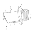
- FIGS 2 and 3 are perspective and top views, respectively, of an exemplary rotor blade 200 of high pressure turbine system 108.
- rotor blade 200 includes a platform segment 202 and an airfoil 204 integrally formed with, and extending from, platform segment 202.
- airfoil 204 may be configured for use as a stator vane of high pressure turbine system 108.
- airfoil 204 may be configured for use in any suitable system of gas turbine engine 100 (e.g., low pressure turbine system 110).
- airfoil 204 extends in span from a platform segment 202 of rotor blade 200 to a blade tip 206 of rotor blade 200.
- Airfoil 204 includes a first contoured sidewall 208 and a second contoured sidewall 210 that converge at a leading edge 212 and an opposite trailing edge 214.
- First contoured sidewall 208 is convex and defines a suction side of airfoil 204
- second contoured sidewall 210 is concave and defines a pressure side of airfoil 204.
- airfoil 204 has a generally spanwise configuration 218 of cooling apertures on second contoured sidewall 210 proximate to trailing edge 214.
- sidewalls 208, 210 may have any suitable contours
- configuration 218 of cooling apertures may have any suitable orientation and location on airfoil 204.
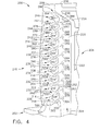
- FIG 4 is a sectional view of airfoil 204 taken along line 4-4 of Figure 3 .
- airfoil 204 has an internal cooling flow passage 220 disposed between first and second sidewalls 208, 210, and passage 220 has a passage axis 222 (i.e., a centerline axis) oriented in a generally spanwise direction such that passage 220 is in flow communication with configuration 218 of cooling apertures, as described in more detail below.
- passage axis 222 i.e., a centerline axis
- Configuration 218 of cooling apertures includes an inner boundary 224, an outer boundary 226, and a plurality of spaced-apart guide fingers that are integrally formed with first contoured sidewall 208 and second contoured sidewall 210, namely a first guide finger 228, a second guide finger 230, a third guide finger 232, a fourth guide finger 234, a fifth guide finger 236, a sixth guide finger 238, a seventh guide finger 240, an eighth guide finger 242, a ninth guide finger 244, and a tenth guide finger 246.
- Each guide finger 228, 230, 232, 234, 236, 238, 240, 242, 244, 246 has an inner contour 248 and an outer contour 250 joined together at, and extending between, a base surface 252 and a finger tip 254.
- base surfaces 252 are oriented to be substantially parallel to passage axis 222.
- base surfaces 252 may have any suitable orientation that facilitates enabling airfoil 204 to function as described herein.
- airfoil 204 may have any suitable number of guide fingers.
- the term “inner” refers to being located closer to platform segment 202 than to blade tip 206 along the span of airfoil 204, and the term “outer” refers to being located closer to blade tip 206 than to platform segment 202 along the span of airfoil 204.
- the term “inwardly facing” refers to facing toward platform segment 202 rather than facing toward blade tip 206, and the term “outwardly facing” refers to facing toward blade tip 206 rather than facing toward platform segment 202.
- a first flow path 256 is defined between inner boundary 224 and inner contour 248 of first guide finger 228 along a first flow path axis 258 (i.e., a centerline axis);
- a second flow path 260 is defined between outer contour 250 of first guide finger 228 and inner contour 248 of second guide finger 230 along a second flow path axis 262 (i.e., a centerline axis);
- a third flow path 264 is defined between outer contour 250 of second guide finger 230 and inner contour 248 of third guide finger 232 along a third flow path axis 266 (i.e., a centerline axis);
- a fourth flow path 268 is defined between outer contour 250 of third guide finger 232 and inner contour 248 of fourth guide finger 234 along a fourth flow path axis 270 (i.e., a centerline axis);
- a fifth flow path 272 is defined between outer contour 250 of fourth guide finger 234 and inner contour 248 of fifth guide finger 236 along
- First flow path 256 includes a first channel segment 300 and a first delta segment 302, and first channel segment 300 is contoured such that first flow path axis 258 intersects passage axis 222 at a first inwardly facing acute angle 304 and intersects trailing edge 214 at a first substantially right angle 306.
- Second flow path 260 includes a second channel segment 308 and a second delta segment 310, and second channel segment 308 is contoured such that second flow path axis 262 intersects passage axis 222 at a second inwardly facing acute angle 312 and intersects trailing edge 214 at a second substantially right angle 314.
- Third flow path 264 includes a third channel segment 316 and a third delta segment 318, and third channel segment 316 is contoured such that third flow path axis 266 intersects passage axis 222 at a third inwardly facing acute angle 320 and intersects trailing edge 214 at a third substantially right angle 322.
- Fourth flow path 268 includes a fourth channel segment 324 and a fourth delta segment 326, and fourth channel segment 324 is contoured such that fourth flow path axis 270 intersects passage axis 222 at a fourth inwardly facing acute angle 328 and intersects trailing edge 214 at a fourth substantially right angle 330.
- Fifth flow path 272 includes a fifth channel segment 332 and a fifth delta segment 334, and fifth channel segment 332 is contoured such that fifth flow path axis 274 intersects passage axis 222 at a fifth inwardly facing acute angle 336 and intersects trailing edge 214 at a fifth substantially right angle 338.
- sixth flow path 276 includes a sixth channel segment 340 and a sixth delta segment 342, and sixth channel segment 340 is contoured such that sixth flow path axis 278 intersects passage axis 222 at a sixth inwardly facing acute angle 344 and intersects trailing edge 214 at a sixth substantially right angle 346.
- Seventh flow path 280 includes a seventh channel segment 348 and a seventh delta segment 350, and seventh channel segment 348 is contoured such that seventh flow path axis 282 intersects passage axis 222 at a seventh inwardly facing acute angle 352 and intersects trailing edge 214 at a seventh substantially right angle 354.
- Eighth flow path 284 includes an eighth channel segment 356 and an eighth delta segment 358, and eighth channel segment 356 is contoured such that eighth flow path axis 286 intersects passage axis 222 at an eighth inwardly facing acute angle 360 and intersects trailing edge 214 at an eighth substantially right angle 362.
- Ninth flow path 288 includes a ninth channel segment 364 and a ninth delta segment 366, and ninth channel segment 364 is contoured such that ninth flow path axis 290 intersects passage axis 222 at a ninth inwardly facing acute angle 368 and intersects trailing edge 214 at a ninth substantially right angle 370.
- each axis 258, 262, 266, 270, 274, 278, 282, 286, 290 is broken (e.g., is angled or changes direction) at an intermediate segment of its respective flow path 256, 260, 264, 268, 272, 276, 280, 284, 288.
- flow paths 256, 260, 264, 268, 272, 276, 280, 284, 288 receive cooling air in a first direction that is acute relative to passage axis 222 and discharge the cooling air in a second direction that is different than the first direction and is substantially perpendicular to trailing edge 214.
- each channel segment 300, 308, 316, 324, 332, 340, 348, 356, 364 is generally L-shaped. In other embodiments, channel segments 300, 308, 316, 324, 332, 340, 348, 356, 364 may have any suitable shapes that enable flow paths 256, 260, 264, 268, 272, 276, 280, 284, 288 to receive and discharge cooling air as described herein.
- tenth flow path 292 includes a tenth channel segment 372 and a tenth delta segment 374, and tenth channel segment 372 is contoured such that tenth flow path axis 294 intersects passage axis 222 and trailing edge 214 at tenth substantially right angles 376, 378.
- eleventh flow path 296 includes an eleventh channel segment 382 and an eleventh delta segment 384, and eleventh channel segment 382 is contoured such that eleventh flow path axis 298 intersects passage axis 222 at an eleventh outwardly facing acute angle 386.
- a flow 394 of cooling air is directed through passage 220 along passage axis 222 and is discharged from passage 220 via flow paths 256, 260, 264, 268, 272, 276, 280, 284, 288, 292, 296.
- flow paths 256, 260, 264, 268, 272, 276, 280, 284, 288 have flow path axes 258, 262, 266, 270, 274, 278, 282, 286, 290 that are oriented at inwardly facing acute angles 304, 312, 320, 328, 336, 344, 352, 360, 368, the flow 394 of cooling air in passage 220 slows upon entry into flow paths 256, 260, 264, 268, 272, 276, 280, 284, 288.
- channel segments 300, 308, 316, 324, 332, 340, 348, 356, 364 relative to passage axis 222 create more tortuous paths for the cooling air and, therefore, facilitate slowing the cooling air upon entry into flow paths 256, 260, 264, 268, 272, 276, 280, 284, 288 from passage 220, thereby reducing the rate at which the cooling air is discharged from flow paths 256, 260, 264, 268, 272, 276, 280, 284, 288.
- cooling air enters tenth flow path 292 at a higher rate than the rate at which cooling air enters flow paths 256, 260, 264, 268, 272, 276, 280, 284, 288.
- eleventh flow path axis 298 intersects passage axis 222 at eleventh outwardly facing acute angle 386, cooling air enters eleventh flow path 296 at a higher rate than the rate at which cooling air enters tenth flow path 292.
- delta segments 302, 310, 318, 326, 334, 342, 350, 358, 366, 374, 384 facilitate spreading the cooling air exiting channel segments 300, 308, 316, 324, 332, 340, 348, 356, 364, 372, 382 such that cooling air is discharged from configuration 218 along the entirety of trailing edge 214 to facilitate cooling airfoil 204 at trailing edge 214.
- configuration 218 of cooling apertures is a configuration of trailing edge cooling apertures in the exemplary embodiment, the methods and systems described herein would be useful with respect to any suitable configuration of cooling apertures located in any suitable segment of gas turbine engine 100.
- the methods and systems described herein facilitate providing an improved turbine airfoil trailing edge cooling slot geometry for discharging cooling air from an airfoil.
- the methods and systems described herein further facilitate providing cooling flow slots that facilitate reducing parasitic airfoil cooling flow and/or providing enhanced durability of the airfoil with reduced trailing edge metal temperature and thermal gradient.
- the methods and systems described herein also facilitate reducing cooling slot effective flow and maintaining high slot film cooling effectiveness as a result of flow separation at the slot inlet due to the slot inlet angle.
- the methods and systems described herein further facilitate providing a desirable slot flow exit angle orientation being aligned with the mainstream hot gas flow along the airfoil chord, thereby maintaining high film cooling effectiveness downstream of the slot breakout on the airfoil.
- the methods and systems described herein therefore facilitate a net result of obtaining lower airfoil metal temperatures with a lower cooling flow discharge rate.
- the methods and systems described herein facilitate providing a cooling slot configuration that enables a reduction in land size and metal temperature, which is desirable for advanced engines operating at significantly higher turbine inlet temperatures where the land temperatures become limiting.
- the methods and systems described herein further facilitate providing a cooling advantage through the subsequent increase in slot area and reduced land area.
- the methods and systems described herein can therefore be used for achieving a specific fuel consumption (SFC) benefit by reducing parasitic cooling flow level at a given airfoil durability or can be used for increasing airfoil durability while maintaining a given SFC level.
- SFC specific fuel consumption
Landscapes
- Engineering & Computer Science (AREA)
- Mechanical Engineering (AREA)
- General Engineering & Computer Science (AREA)
- Turbine Rotor Nozzle Sealing (AREA)
Applications Claiming Priority (1)
| Application Number | Priority Date | Filing Date | Title |
|---|---|---|---|
| US13/285,783 US8790084B2 (en) | 2011-10-31 | 2011-10-31 | Airfoil and method of fabricating the same |
Publications (2)
| Publication Number | Publication Date |
|---|---|
| EP2594740A2 true EP2594740A2 (de) | 2013-05-22 |
| EP2594740A3 EP2594740A3 (de) | 2018-05-23 |
Family
ID=47073359
Family Applications (1)
| Application Number | Title | Priority Date | Filing Date |
|---|---|---|---|
| EP12190285.2A Withdrawn EP2594740A3 (de) | 2011-10-31 | 2012-10-26 | Tragflügel und Verfahren zu seiner Herstellung |
Country Status (6)
| Country | Link |
|---|---|
| US (1) | US8790084B2 (de) |
| EP (1) | EP2594740A3 (de) |
| JP (1) | JP2013096408A (de) |
| CN (1) | CN103089325B (de) |
| BR (1) | BR102012027855A2 (de) |
| CA (1) | CA2793459A1 (de) |
Families Citing this family (5)
| Publication number | Priority date | Publication date | Assignee | Title |
|---|---|---|---|---|
| US10301954B2 (en) | 2016-01-08 | 2019-05-28 | General Electric Company | Turbine airfoil trailing edge cooling passage |
| US20170306775A1 (en) * | 2016-04-21 | 2017-10-26 | General Electric Company | Article, component, and method of making a component |
| CN111022127B (zh) * | 2019-11-29 | 2021-12-03 | 大连理工大学 | 一种涡轮叶片尾缘曲线式排气劈缝结构 |
| US20220307381A1 (en) * | 2021-03-24 | 2022-09-29 | General Electric Company | Component assembly for a combustion section of a gas turbine engine |
| US12162109B2 (en) * | 2022-05-27 | 2024-12-10 | General Electric Company | System and method for contouring edges of airfoils |
Family Cites Families (21)
| Publication number | Priority date | Publication date | Assignee | Title |
|---|---|---|---|---|
| US3017159A (en) * | 1956-11-23 | 1962-01-16 | Curtiss Wright Corp | Hollow blade construction |
| US3628885A (en) * | 1969-10-01 | 1971-12-21 | Gen Electric | Fluid-cooled airfoil |
| FR2476207A1 (fr) * | 1980-02-19 | 1981-08-21 | Snecma | Perfectionnement aux aubes de turbines refroidies |
| US5243759A (en) * | 1991-10-07 | 1993-09-14 | United Technologies Corporation | Method of casting to control the cooling air flow rate of the airfoil trailing edge |
| US5503529A (en) * | 1994-12-08 | 1996-04-02 | General Electric Company | Turbine blade having angled ejection slot |
| JP3786458B2 (ja) * | 1996-01-19 | 2006-06-14 | 株式会社東芝 | 軸流タービン翼 |
| US5772397A (en) * | 1996-05-08 | 1998-06-30 | Alliedsignal Inc. | Gas turbine airfoil with aft internal cooling |
| SE512384C2 (sv) * | 1998-05-25 | 2000-03-06 | Abb Ab | Komponent för en gasturbin |
| US6164913A (en) | 1999-07-26 | 2000-12-26 | General Electric Company | Dust resistant airfoil cooling |
| US6257831B1 (en) * | 1999-10-22 | 2001-07-10 | Pratt & Whitney Canada Corp. | Cast airfoil structure with openings which do not require plugging |
| US6270317B1 (en) | 1999-12-18 | 2001-08-07 | General Electric Company | Turbine nozzle with sloped film cooling |
| US6602047B1 (en) | 2002-02-28 | 2003-08-05 | General Electric Company | Methods and apparatus for cooling gas turbine nozzles |
| US6746209B2 (en) | 2002-05-31 | 2004-06-08 | General Electric Company | Methods and apparatus for cooling gas turbine engine nozzle assemblies |
| SE526847C2 (sv) * | 2004-02-27 | 2005-11-08 | Demag Delaval Ind Turbomachine | En komponent som innefattar en ledskena eller ett rotorblad för en gasturbin |
| US20050235492A1 (en) * | 2004-04-22 | 2005-10-27 | Arness Brian P | Turbine airfoil trailing edge repair and methods therefor |
| US7210906B2 (en) * | 2004-08-10 | 2007-05-01 | Pratt & Whitney Canada Corp. | Internally cooled gas turbine airfoil and method |
| US7156619B2 (en) * | 2004-12-21 | 2007-01-02 | Pratt & Whitney Canada Corp. | Internally cooled gas turbine airfoil and method |
| US7806650B2 (en) | 2006-08-29 | 2010-10-05 | General Electric Company | Method and apparatus for fabricating a nozzle segment for use with turbine engines |
| US20080152475A1 (en) | 2006-12-21 | 2008-06-26 | Jack Raul Zausner | Method for preventing backflow and forming a cooling layer in an airfoil |
| US20090003987A1 (en) | 2006-12-21 | 2009-01-01 | Jack Raul Zausner | Airfoil with improved cooling slot arrangement |
| US7837437B2 (en) | 2007-03-07 | 2010-11-23 | General Electric Company | Turbine nozzle segment and repair method |
-
2011
- 2011-10-31 US US13/285,783 patent/US8790084B2/en active Active
-
2012
- 2012-10-23 JP JP2012233354A patent/JP2013096408A/ja active Pending
- 2012-10-25 CA CA2793459A patent/CA2793459A1/en not_active Abandoned
- 2012-10-26 EP EP12190285.2A patent/EP2594740A3/de not_active Withdrawn
- 2012-10-30 BR BR102012027855A patent/BR102012027855A2/pt not_active IP Right Cessation
- 2012-10-31 CN CN201210426157.1A patent/CN103089325B/zh active Active
Non-Patent Citations (1)
| Title |
|---|
| None |
Also Published As
| Publication number | Publication date |
|---|---|
| CN103089325B (zh) | 2016-01-20 |
| US8790084B2 (en) | 2014-07-29 |
| CN103089325A (zh) | 2013-05-08 |
| BR102012027855A2 (pt) | 2015-09-15 |
| CA2793459A1 (en) | 2013-04-30 |
| EP2594740A3 (de) | 2018-05-23 |
| JP2013096408A (ja) | 2013-05-20 |
| US20130108469A1 (en) | 2013-05-02 |
Similar Documents
| Publication | Publication Date | Title |
|---|---|---|
| US8043063B2 (en) | Intentionally mistuned integrally bladed rotor | |
| US10415392B2 (en) | End wall configuration for gas turbine engine | |
| EP2825748B1 (de) | Kühlkanal für ein gasturbinentriebwerk und gasturbinentriebwerk | |
| US8439643B2 (en) | Biformal platform turbine blade | |
| US9279329B2 (en) | Transonic blade | |
| US8985940B2 (en) | Turbine cooling apparatus | |
| EP1273758B1 (de) | Verfahren und Vorrichtung zur Filmkühlung eines Schaufelblatts | |
| EP2586983A2 (de) | Bauteil einer Gasturbine und Verfahren zu ihrer Herstellung | |
| US10648342B2 (en) | Engine component with cooling hole | |
| EP3156596A1 (de) | Turbinenschaufel | |
| EP2900918A2 (de) | Stirnwandkonturierung | |
| CN106884683B (zh) | 利用薄膜冷却的发动机构件 | |
| EP2900919B1 (de) | Wandkonturierung | |
| US8790084B2 (en) | Airfoil and method of fabricating the same | |
| US10830060B2 (en) | Engine component with flow enhancer | |
| CN107762566A (zh) | 带有多孔末梢的用于涡轮发动机的翼型件 | |
| US10107107B2 (en) | Gas turbine engine component with discharge slot having oval geometry | |
| CN107762564A (zh) | 带有多孔肋部的用于涡轮发动机的翼型件 | |
| EP3184736A1 (de) | Angewinkeltes wärmetransfergestell | |
| CN109083687B (zh) | 最小化横穿冷却孔的横流的方法和用于涡轮发动机的部件 |
Legal Events
| Date | Code | Title | Description |
|---|---|---|---|
| PUAI | Public reference made under article 153(3) epc to a published international application that has entered the european phase |
Free format text: ORIGINAL CODE: 0009012 |
|
| AK | Designated contracting states |
Kind code of ref document: A2 Designated state(s): AL AT BE BG CH CY CZ DE DK EE ES FI FR GB GR HR HU IE IS IT LI LT LU LV MC MK MT NL NO PL PT RO RS SE SI SK SM TR |
|
| AX | Request for extension of the european patent |
Extension state: BA ME |
|
| PUAL | Search report despatched |
Free format text: ORIGINAL CODE: 0009013 |
|
| AK | Designated contracting states |
Kind code of ref document: A3 Designated state(s): AL AT BE BG CH CY CZ DE DK EE ES FI FR GB GR HR HU IE IS IT LI LT LU LV MC MK MT NL NO PL PT RO RS SE SI SK SM TR |
|
| AX | Request for extension of the european patent |
Extension state: BA ME |
|
| RIC1 | Information provided on ipc code assigned before grant |
Ipc: B24B 55/02 20060101ALI20180413BHEP Ipc: F01D 5/18 20060101AFI20180413BHEP |
|
| STAA | Information on the status of an ep patent application or granted ep patent |
Free format text: STATUS: THE APPLICATION IS DEEMED TO BE WITHDRAWN |
|
| 18D | Application deemed to be withdrawn |
Effective date: 20180501 |