EP2594708A2 - Head piece for a ground anchor - Google Patents
Head piece for a ground anchor Download PDFInfo
- Publication number
- EP2594708A2 EP2594708A2 EP12192619.0A EP12192619A EP2594708A2 EP 2594708 A2 EP2594708 A2 EP 2594708A2 EP 12192619 A EP12192619 A EP 12192619A EP 2594708 A2 EP2594708 A2 EP 2594708A2
- Authority
- EP
- European Patent Office
- Prior art keywords
- stabilizing device
- load element
- ground anchor
- sleeve
- plate member
- Prior art date
- Legal status (The legal status is an assumption and is not a legal conclusion. Google has not performed a legal analysis and makes no representation as to the accuracy of the status listed.)
- Granted
Links
- 230000000087 stabilizing effect Effects 0.000 claims abstract description 72
- 239000000463 material Substances 0.000 claims abstract description 7
- 230000000295 complement effect Effects 0.000 claims abstract description 4
- 230000008878 coupling Effects 0.000 claims description 10
- 238000010168 coupling process Methods 0.000 claims description 10
- 238000005859 coupling reaction Methods 0.000 claims description 10
- 238000000034 method Methods 0.000 claims description 8
- 238000009434 installation Methods 0.000 claims description 4
- 238000005452 bending Methods 0.000 description 4
- 230000009286 beneficial effect Effects 0.000 description 3
- 229910000831 Steel Inorganic materials 0.000 description 1
- 238000010420 art technique Methods 0.000 description 1
- 230000006835 compression Effects 0.000 description 1
- 238000007906 compression Methods 0.000 description 1
- 239000010959 steel Substances 0.000 description 1
Images

Classifications
-
- E—FIXED CONSTRUCTIONS
- E02—HYDRAULIC ENGINEERING; FOUNDATIONS; SOIL SHIFTING
- E02D—FOUNDATIONS; EXCAVATIONS; EMBANKMENTS; UNDERGROUND OR UNDERWATER STRUCTURES
- E02D5/00—Bulkheads, piles, or other structural elements specially adapted to foundation engineering
- E02D5/74—Means for anchoring structural elements or bulkheads
- E02D5/80—Ground anchors
-
- E—FIXED CONSTRUCTIONS
- E02—HYDRAULIC ENGINEERING; FOUNDATIONS; SOIL SHIFTING
- E02D—FOUNDATIONS; EXCAVATIONS; EMBANKMENTS; UNDERGROUND OR UNDERWATER STRUCTURES
- E02D5/00—Bulkheads, piles, or other structural elements specially adapted to foundation engineering
- E02D5/74—Means for anchoring structural elements or bulkheads
- E02D5/80—Ground anchors
- E02D5/803—Ground anchors with pivotable anchoring members
-
- E—FIXED CONSTRUCTIONS
- E04—BUILDING
- E04H—BUILDINGS OR LIKE STRUCTURES FOR PARTICULAR PURPOSES; SWIMMING OR SPLASH BATHS OR POOLS; MASTS; FENCING; TENTS OR CANOPIES, IN GENERAL
- E04H12/00—Towers; Masts or poles; Chimney stacks; Water-towers; Methods of erecting such structures
- E04H12/22—Sockets or holders for poles or posts
- E04H12/2207—Sockets or holders for poles or posts not used
- E04H12/2215—Sockets or holders for poles or posts not used driven into the ground
Definitions
- the present invention relates to a stabilizing device for a load element of a ground anchor.
- Such stabilizing device is known from DE1928145 of Dahl, Gunnar .
- This publication discloses a stabilizing device.
- the stabilizing device is not robust in use.
- the stabilizing device is prone to bending outwards of plate material specifically when driving the device into the ground and during use when the device is subjected to severe lateral loads caused by canting of the load element, in this case a pipe.
- the invention further relates to an assembly of a ground anchor having a load element and a stabilizing device.
- the invention further relates to a method for installation of an assembly of a ground anchor having a load element and a stabilizing device.
- the invention aims to at least partly solve a problem associated with a known stabilizing device for a load element of a ground anchor.
- Another object of the invention is to improve stabilizing device for a load element of a ground anchor.
- another object of the invention is to provide a stabilizing device for a load element of a ground anchor, wherein the stabilizing device has an improved strength.
- Yet another object of the invention is to provide an alternative stabilizing device for a load element of a ground anchor.
- a stabilizing device for a load element of a ground anchor consisting of two plate members, wherein the plate members have a generally L-shape and are complementary and do form a generally cross shape when coupled together and when coupled together form a feed through sleeve for leading the load element there through, wherein each plate member comprises at least one recess surrounded by plate material, which at least one recess of each plate member receives a central feed through sleeve forming plate member portion when the plate members are coupled together for forming the generally cross shaped stabilizing device.
- the stabilizing device is more robust in connection with driving of the stabilizing device into the ground.
- a stabilizing device for a load element of a ground anchor specifically stabilizes the load element with respect to lateral loads such that the load element maintains its position when subjected to lateral loads.
- a load element may be an elongate tension member like a cable or a compression member like a rod or a pile depending on the type of ground anchor. Such an elongate load element couples the ground anchor with the load to be anchored. The elongate load element, when not stabilized, easily cuts through the ground when subjected to lateral loads and thus may leave its intended position, which is undesirable.
- the two plate members are similar, preferably identical. This makes the stabilizing more efficient in use and during transportation.
- the feed through sleeve is arranged centrally with respect to the stabilizing device.
- each plate member comprises a plurality of recesses, in a specific embodiment two recesses. This makes the stabilizing device even more robust because loads are better distributed along the height of the plate members.
- this is realized with an assembly of a ground anchor having a load element and a stabilizing device according to the invention, wherein the load element is fed through the central feed through sleeve.
- the load element is coupled with the stabilizing device in a slideable manner.
- the assembly comprises coupling means for fixedly coupling the load element with the stabilizing device once the earth anchor and the stabilizing device have taken their desired position.
- the coupling means are provided with the upper and/or lower side of the stabilizing device for fixedly coupling the load element with the stabilizing device at the upper and/or lower side of the stabilizing device.
- the ground anchor is a pivoting anchor.
- a pivoting ground anchor it is even more beneficial to be coupled with the stabilizing device in a slideable manner because the load element needs to be taken in to deploy or set the pivoting anchor.
- the ground anchor is a pivoting ground anchor, and the method further comprises the step;
- the invention further relates to a device comprising one or more of the characterising features described in the description and/or shown in the attached drawings.
- the invention further relates to a method comprising one or more of the characterising features described in the description and/or shown in the attached drawings.
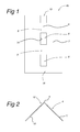
- a plate member 4b of the stabilizing device 1 is shown.
- a plate member 4b is made of steel by cutting and bending. Any other suitable material for such a plate member is conceivable.
- the plate member has a height of 400 cm and a thickness of about 4 cm.
- the plate member 4 is bend along a, here central, bending line 9 which gives the plate member 4 a L-shape.
- the plate member 4 has two legs 10, 11 which legs are mutually arranged transversely. In this case the two legs 10, 11 have similar length of about 180 cm. These legs 10, 11 in use extend in the ground for accommodating side loads to the stabilizing device 1. It will be clear that the plate member 4b may have other dimensions.
- the stabilizing device 1 for a load element 2 of a ground anchor 3 consists of two plate members 4a, 4b.
- the plate members 4a and 4b are complementary for coupling the two plate members 4a, 4b together at their respective bending lines 9.
- the two plate members 44a, 4b are identical.
- they form a generally cross shape.
- a feed through sleeve 5 is formed for leading a load element 2 there through.
- the feed through sleeve is defined by the bend sections 12 of the two respective plate members 4a, 4b, specifically by the inside of the two respective bend sections 12.
- each respective plate member 4a, 4b comprises two recesses 6 surrounded by plate material 7. Another number of such recesses 6 is conceivable.
- each respective plate member 4a, 4b has a cut-away 15 which receives an opposite bend portion 16 when the two plate members 4a, 4b are coupled together.
- the recess 6 is defined by a recess outline 14.
- the recess is outline 14 is continuous, in other words uninterrupted.
- the recess outline 14 has a rectangular shape.
- each respective plate member 4a, 4b receives a respective central feed through sleeve forming plate member portion 8.
- one plate member 4b is positioned as shown in fig. 1 .
- the other plate member 4a is turned upside down with respect to the one plate member 4b of fig. 1 .
- the two plate members 4a, 4b are then coupled at their respective bend sections 9 such that all the respective central feed through sleeve forming plate member portion 8 of one plate member 4a, extend past the other plate member 4b.
- the two plate members 4a, 4b then do form in conjunction the sleeve 5.
- the feed through sleeve 5 is arranged centrally with respect to the stabilizing device 1.
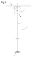
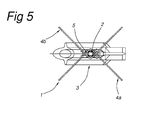
- Fig 4 and 5 show an assembly 17 of the stabilizing device 1 and a ground anchor 3.
- the load element 3 of the ground anchor 3 is fed through the central feed through sleeve 5 of the stabilizing device 1.
- the load element 2 s coupled with the stabilizing device 1 in a slideable manner.
- the load element 2 may be provided with threading (not shown) for enabling use of a nut or the like for forming a stop for the stabilizing device 1.
- the stabilizing device 1 is particularly useful in the assembly 17 with a pivoting ground anchor 3.
- the ground anchor 3 with a load element 2 is applied in the ground below the ground level 13 in a manner known per se at a depth of for instance a few meters.
- the stabilizing device 1 is slid around the load element 2 wherein the load element 2 is fed into the sleeve 5 along the entire height of the stabilizing device 1.
- the stabilizing device 1 is driven in the ground while sliding the stabilizing device 1 with respect to the load element 2.
- the stabilizing device 1 is driven in the ground in a manner known per se, like hammering.
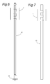
- the stabilizing device 1 of the invention is also beneficial in an assembly shown in fig. 6 with a ground anchor 19 which can take up both tensile and compressive forces.
- the load element, here a rod 18 is also able to take up both tensile and compressive forces.
- the stabilizing device 1 of the invention is also beneficial in an assembly shown in fig. 7 with a pile 20 for use as foundation.
Landscapes
- Engineering & Computer Science (AREA)
- Structural Engineering (AREA)
- Civil Engineering (AREA)
- Life Sciences & Earth Sciences (AREA)
- General Life Sciences & Earth Sciences (AREA)
- Mining & Mineral Resources (AREA)
- Paleontology (AREA)
- General Engineering & Computer Science (AREA)
- Architecture (AREA)
- Piles And Underground Anchors (AREA)
Abstract
Description
- The present invention relates to a stabilizing device for a load element of a ground anchor.
- Such stabilizing device is known from
DE1928145 of Dahl, Gunnar . This publication discloses a stabilizing device. However the device is not robust in use. The stabilizing device is prone to bending outwards of plate material specifically when driving the device into the ground and during use when the device is subjected to severe lateral loads caused by canting of the load element, in this case a pipe. - The invention further relates to an assembly of a ground anchor having a load element and a stabilizing device.
- The invention further relates to a method for installation of an assembly of a ground anchor having a load element and a stabilizing device.
- The invention aims to at least partly solve a problem associated with a known stabilizing device for a load element of a ground anchor.
- Another object of the invention is to improve stabilizing device for a load element of a ground anchor.
- Still, another object of the invention is to provide a stabilizing device for a load element of a ground anchor, wherein the stabilizing device has an improved strength.
- Yet another object of the invention is to provide an alternative stabilizing device for a load element of a ground anchor.
- According to a first aspect of the invention this is realized with a stabilizing device for a load element of a ground anchor, the device consisting of two plate members, wherein the plate members have a generally L-shape and are complementary and do form a generally cross shape when coupled together and when coupled together form a feed through sleeve for leading the load element there through, wherein each plate member comprises at least one recess surrounded by plate material, which at least one recess of each plate member receives a central feed through sleeve forming plate member portion when the plate members are coupled together for forming the generally cross shaped stabilizing device.
- This provides the possibility of forming the sleeve by recesses surrounded by plate material that gives a much better performance under side loads when the load element is canted. In addition, the stabilizing device is more robust in connection with driving of the stabilizing device into the ground.
- A stabilizing device for a load element of a ground anchor, specifically stabilizes the load element with respect to lateral loads such that the load element maintains its position when subjected to lateral loads. A load element may be an elongate tension member like a cable or a compression member like a rod or a pile depending on the type of ground anchor. Such an elongate load element couples the ground anchor with the load to be anchored. The elongate load element, when not stabilized, easily cuts through the ground when subjected to lateral loads and thus may leave its intended position, which is undesirable.
- In an embodiment of the invention, the two plate members are similar, preferably identical. This makes the stabilizing more efficient in use and during transportation.
- In an embodiment of the invention, the feed through sleeve is arranged centrally with respect to the stabilizing device.
- In an embodiment of the invention, each plate member comprises a plurality of recesses, in a specific embodiment two recesses. This makes the stabilizing device even more robust because loads are better distributed along the height of the plate members.
- According to a further aspect of the invention this is realized with an assembly of a ground anchor having a load element and a stabilizing device according to the invention, wherein the load element is fed through the central feed through sleeve.
- In an embodiment of the assembly, the load element is coupled with the stabilizing device in a slideable manner.
- In an embodiment the assembly comprises coupling means for fixedly coupling the load element with the stabilizing device once the earth anchor and the stabilizing device have taken their desired position.
- In an embodiment of the assembly, the coupling means are provided with the upper and/or lower side of the stabilizing device for fixedly coupling the load element with the stabilizing device at the upper and/or lower side of the stabilizing device.
- In an embodiment of the assembly, the ground anchor is a pivoting anchor. For a pivoting ground anchor it is even more beneficial to be coupled with the stabilizing device in a slideable manner because the load element needs to be taken in to deploy or set the pivoting anchor.
- According to an even further aspect of the invention this is realized with a method for installation of an assembly of a ground anchor having a load element and a stabilizing device according to the invention, comprising the steps;
- placing a ground anchor with a load element,
- sliding a stabilizing device according to a preceding claim around the load element for accommodating the load element at least partly in the feed through sleeve,
- driving the stabilizing device in the ground while sliding the stabilizing device with respect to the load element,
- In an embodiment of the method the ground anchor is a pivoting ground anchor, and the method further comprises the step;
- taking in the load element through the feed through sleeve for pivoting the ground anchor.
- The invention further relates to a device comprising one or more of the characterising features described in the description and/or shown in the attached drawings.
- The invention further relates to a method comprising one or more of the characterising features described in the description and/or shown in the attached drawings.
- The various aspects discussed in this patent can be combined in order to provide additional advantageous advantages.
- The invention will be further elucidated referring to an preferred embodiment shown in the drawing wherein shown in:
- Fig. 1
- in side view a plate member of the stabilizing device;
- fig. 2
- a top view of the plate member of
fig. 1 ; - fig. 3
- a perspective view of the stabilizing device;
- fig 4
- an assembly of the stabilizing device and a ground anchor;
- fig. 5
- a top view of the assembly of
fig. 3 ; - fig 6
- an assembly of the stabilizing device and another type of ground anchor; and
- fig. 7
- an assembly of the stabilizing device and a pile.
- The invention will now be described referring to all
figures 1-5 . InFig. 1 aplate member 4b of the stabilizingdevice 1 is shown. In general such aplate member 4b is made of steel by cutting and bending. Any other suitable material for such a plate member is conceivable. The plate member has a height of 400 cm and a thickness of about 4 cm. The plate member 4 is bend along a, here central, bendingline 9 which gives theplate member 4 a L-shape. The plate member 4 has twolegs legs legs device 1. It will be clear that theplate member 4b may have other dimensions. - The stabilizing
device 1 for aload element 2 of aground anchor 3 consists of twoplate members plate members plate members respective bending lines 9. In this case the twoplate members 44a, 4b are identical. When the twoplate members - In addition, when the two
plate members sleeve 5 is formed for leading aload element 2 there through. The feed through sleeve is defined by thebend sections 12 of the tworespective plate members respective bend sections 12. - Here, each
respective plate member 4a, 4bcomprises tworecesses 6 surrounded byplate material 7. Another number ofsuch recesses 6 is conceivable. In addition, eachrespective plate member opposite bend portion 16 when the twoplate members recess 6 is defined by arecess outline 14. The recess isoutline 14 is continuous, in other words uninterrupted. Here, therecess outline 14 has a rectangular shape. - When the two
plate members device 1, here all the recesses of eachrespective plate member plate member portion 8. For coupling the twoplate members plate member 4b is positioned as shown infig. 1 . Theother plate member 4a is turned upside down with respect to the oneplate member 4b offig. 1 . The twoplate members respective bend sections 9 such that all the respective central feed through sleeve formingplate member portion 8 of oneplate member 4a, extend past theother plate member 4b. The twoplate members sleeve 5. Here, the feed throughsleeve 5 is arranged centrally with respect to the stabilizingdevice 1. -
Fig 4 and5 show anassembly 17 of the stabilizingdevice 1 and aground anchor 3. Theload element 3 of theground anchor 3 is fed through the central feed throughsleeve 5 of the stabilizingdevice 1. The load element 2 s coupled with the stabilizingdevice 1 in a slideable manner. Theload element 2 may be provided with threading (not shown) for enabling use of a nut or the like for forming a stop for the stabilizingdevice 1. - The stabilizing
device 1 is particularly useful in theassembly 17 with a pivotingground anchor 3. - In use, during installation of the
assembly 17, the following steps are taken; - Firstly the
ground anchor 3 with aload element 2 is applied in the ground below theground level 13 in a manner known per se at a depth of for instance a few meters. - Then the stabilizing
device 1 is slid around theload element 2 wherein theload element 2 is fed into thesleeve 5 along the entire height of the stabilizingdevice 1. - Subsequently, the stabilizing
device 1 is driven in the ground while sliding the stabilizingdevice 1 with respect to theload element 2. The stabilizingdevice 1 is driven in the ground in a manner known per se, like hammering. - When the
ground anchor 3 is a pivotingground anchor 3, in use of the assembly the following step will additionally be taken; - Taking in, that is sliding, the
load element 2 through the feed throughsleeve 5 for pivoting theground anchor 3 in a manner known per se. - The stabilizing
device 1 of the invention is also beneficial in an assembly shown infig. 6 with aground anchor 19 which can take up both tensile and compressive forces. The load element, here arod 18 is also able to take up both tensile and compressive forces. - The stabilizing
device 1 of the invention is also beneficial in an assembly shown infig. 7 with apile 20 for use as foundation. - It will also be obvious after the above description and drawings are included to illustrate some embodiments of the invention, and not to limit the scope of protection. Starting from this disclosure, many more embodiments will be evident to a skilled person which are within the scope of protection and the essence of this invention and which are obvious combinations of prior art techniques and the disclosure of this patent.
Claims (12)
- Stabilizing device (1) for a load element (2) of a ground anchor (3), the device consisting of two plate members (4a, 4b), wherein the plate members have a generally L-shape and are complementary and do form a generally cross shape when coupled together and when coupled together form a feed through sleeve (5) for leading the load element there through, wherein each plate member comprises at least one recess (6) surrounded by plate material (7), which at least one recess of each plate member receives a central feed through sleeve forming plate member portion (8) when the plate members are coupled together for forming the generally cross shaped stabilizing device (1).
- Stabilizing device according to claim 1, wherein the two plate members are similar, preferably identical.
- Stabilizing device according to a preceding claim, wherein the feed through sleeve (5) is arranged centrally with respect to the stabilizing device.
- Stabilizing device according to a preceding claim, wherein each plate member comprises two recesses.
- Stabilizing device according to a preceding claim, wherein each plate member comprises a plurality of recesses.
- Assembly of a ground anchor having a load element and a stabilizing device according to a preceding claim, wherein the load element is fed through the central feed through sleeve.
- Assembly according to claim 6, wherein the load element is coupled with the stabilizing device in a slideable manner.
- Assembly according to a preceding claim 6-7, comprising coupling means for fixedly coupling the load element with the stabilizing device once the earth anchor and the stabilizing device have taken their desired position.
- Assembly according to claim 8 wherein the coupling means are provided with the upper and/or lower side of the stabilizing device for fixedly coupling the load element with the stabilizing device at the upper and/or lower side of the stabilizing device.
- Assembly according to a preceding claim 6-9, wherein the ground anchor is a pivoting anchor.
- Method for installation of an assembly according to a preceding claim, comprising the steps;- placing a ground anchor with a load element,- sliding a stabilizing device according to a preceding claim around the load element for accommodating the load element at least partly in the feed through sleeve,- driving the stabilizing device in the ground while sliding the stabilizing device with respect to the load element,
- Method according to claim 11, wherein the ground anchor is a pivoting ground anchor, and the method further comprises the step;- taking in the load element through the feed through sleeve for pivoting the ground anchor.
Applications Claiming Priority (2)
| Application Number | Priority Date | Filing Date | Title |
|---|---|---|---|
| US201161559222P | 2011-11-14 | 2011-11-14 | |
| NL2007782A NL2007782C2 (en) | 2011-11-14 | 2011-11-14 | Head piece for a ground anchor. |
Publications (3)
| Publication Number | Publication Date |
|---|---|
| EP2594708A2 true EP2594708A2 (en) | 2013-05-22 |
| EP2594708A3 EP2594708A3 (en) | 2018-02-14 |
| EP2594708B1 EP2594708B1 (en) | 2019-03-13 |
Family
ID=47278656
Family Applications (1)
| Application Number | Title | Priority Date | Filing Date |
|---|---|---|---|
| EP12192619.0A Not-in-force EP2594708B1 (en) | 2011-11-14 | 2012-11-14 | Head piece for a ground anchor |
Country Status (4)
| Country | Link |
|---|---|
| US (1) | US20130121772A1 (en) |
| EP (1) | EP2594708B1 (en) |
| ES (1) | ES2726973T3 (en) |
| NL (1) | NL2007782C2 (en) |
Families Citing this family (5)
| Publication number | Priority date | Publication date | Assignee | Title |
|---|---|---|---|---|
| CA3044662A1 (en) * | 2016-11-29 | 2018-06-07 | Hubbell Incorporated | Supports for helical piles and anchors |
| CA3198410A1 (en) | 2020-10-09 | 2022-04-14 | Hubbell Incorporated | Supports for helical piles |
| USD974150S1 (en) * | 2021-04-06 | 2023-01-03 | Tsan-Jee Chen | Anchor head |
| USD974152S1 (en) * | 2021-06-30 | 2023-01-03 | Tsan-Jee Chen | Anchor head |
| US20250243661A1 (en) * | 2024-01-26 | 2025-07-31 | Charles J. Mackarvich | Building stabilization system |
Citations (1)
| Publication number | Priority date | Publication date | Assignee | Title |
|---|---|---|---|---|
| DE1928145A1 (en) | 1968-06-05 | 1970-01-15 | Gunnar Dahl | Stabilizing device for pipes deposited in the ground |
Family Cites Families (5)
| Publication number | Priority date | Publication date | Assignee | Title |
|---|---|---|---|---|
| BE756888A (en) * | 1970-07-03 | 1971-03-30 | Vallourec Lorraine Escaut | SPOUT FOR STAKES OR PILES |
| US3727357A (en) * | 1971-06-07 | 1973-04-17 | Sears Roebuck & Co | Anchor means for tubular post |
| FR2277190A1 (en) * | 1974-07-04 | 1976-01-30 | Bo Michel | Anchor for sea-bed stabilising sheet - has shaft with two bottom plates pivoting outwards to prevent withdrawal |
| FR2422793A1 (en) * | 1978-04-10 | 1979-11-09 | Moraly Paul | ANCHOR INTENDED FOR FIXING IN THE GROUND POSTS OR STAKES AND DEVICE SERVING THE PRESSURE OF THIS ANCHOR |
| US7165915B2 (en) * | 2004-04-27 | 2007-01-23 | Queen Frankie A R | High capacity low profile slab foundation stabilizing apparatus |
-
2011
- 2011-11-14 NL NL2007782A patent/NL2007782C2/en not_active IP Right Cessation
-
2012
- 2012-11-14 US US13/676,276 patent/US20130121772A1/en not_active Abandoned
- 2012-11-14 EP EP12192619.0A patent/EP2594708B1/en not_active Not-in-force
- 2012-11-14 ES ES12192619T patent/ES2726973T3/en active Active
Patent Citations (1)
| Publication number | Priority date | Publication date | Assignee | Title |
|---|---|---|---|---|
| DE1928145A1 (en) | 1968-06-05 | 1970-01-15 | Gunnar Dahl | Stabilizing device for pipes deposited in the ground |
Also Published As
| Publication number | Publication date |
|---|---|
| EP2594708B1 (en) | 2019-03-13 |
| NL2007782C2 (en) | 2013-05-16 |
| EP2594708A3 (en) | 2018-02-14 |
| US20130121772A1 (en) | 2013-05-16 |
| ES2726973T3 (en) | 2019-10-11 |
Similar Documents
| Publication | Publication Date | Title |
|---|---|---|
| EP2594708B1 (en) | Head piece for a ground anchor | |
| US8584413B1 (en) | Easily connectable anchor and pillblock replacement for an embedded wooden post | |
| AU2013227435B2 (en) | Anti-spalling edging | |
| US8353133B2 (en) | Anchor for handling construction elements comprising fixed divergent arms | |
| MX2012002781A (en) | Lifting anchor for a concrete slab. | |
| CN201172916Y (en) | Reinforcement trough split head of concrete products for reinforced concrete slab | |
| KR20150029917A (en) | Corrugated steel reinforced concrete composite structures | |
| US9109340B1 (en) | Pile-supported cable-reinforced building | |
| CN202401478U (en) | Anti-floating anchor bolt bundle | |
| US9212504B1 (en) | Fence post system, construction, and method | |
| CN201843391U (en) | Mesh sheet type fence | |
| CN105460169A (en) | Light-weight angle-adjustable tension anchor | |
| KR101013028B1 (en) | Tofu reinforcement for concrete piles | |
| RU142535U1 (en) | SCREW PILES | |
| WO2011132894A3 (en) | Pile head reinforcement assembly of steel pipe pile | |
| CN201747056U (en) | Supporting structure for casting concrete ring beam | |
| AU2014242367B2 (en) | Pile axial capacity enhancer | |
| RU144966U1 (en) | SCREW PILES | |
| CN203821384U (en) | H-shaped pile with steel strands | |
| US20160347584A1 (en) | Lifting anchor with enhanced loadbearing features | |
| KR20220166602A (en) | An utility pole reinforcement assembly | |
| KR100960610B1 (en) | Reinforcing structure of head part in steel pipe pile for dispersing external force | |
| CN201665870U (en) | Soil cement multi-way anchor pile of a deep foundation pit support | |
| WO2008020342A2 (en) | Foundation piling base and method of underpinning therefor | |
| CN105256827A (en) | Building structure of underground space |
Legal Events
| Date | Code | Title | Description |
|---|---|---|---|
| PUAI | Public reference made under article 153(3) epc to a published international application that has entered the european phase |
Free format text: ORIGINAL CODE: 0009012 |
|
| AK | Designated contracting states |
Kind code of ref document: A2 Designated state(s): AL AT BE BG CH CY CZ DE DK EE ES FI FR GB GR HR HU IE IS IT LI LT LU LV MC MK MT NL NO PL PT RO RS SE SI SK SM TR |
|
| AX | Request for extension of the european patent |
Extension state: BA ME |
|
| PUAL | Search report despatched |
Free format text: ORIGINAL CODE: 0009013 |
|
| AK | Designated contracting states |
Kind code of ref document: A3 Designated state(s): AL AT BE BG CH CY CZ DE DK EE ES FI FR GB GR HR HU IE IS IT LI LT LU LV MC MK MT NL NO PL PT RO RS SE SI SK SM TR |
|
| AX | Request for extension of the european patent |
Extension state: BA ME |
|
| RIC1 | Information provided on ipc code assigned before grant |
Ipc: E02D 5/80 20060101ALI20180108BHEP Ipc: E04H 12/22 20060101AFI20180108BHEP |
|
| STAA | Information on the status of an ep patent application or granted ep patent |
Free format text: STATUS: REQUEST FOR EXAMINATION WAS MADE |
|
| 17P | Request for examination filed |
Effective date: 20180723 |
|
| RBV | Designated contracting states (corrected) |
Designated state(s): AL AT BE BG CH CY CZ DE DK EE ES FI FR GB GR HR HU IE IS IT LI LT LU LV MC MK MT NL NO PL PT RO RS SE SI SK SM TR |
|
| GRAP | Despatch of communication of intention to grant a patent |
Free format text: ORIGINAL CODE: EPIDOSNIGR1 |
|
| STAA | Information on the status of an ep patent application or granted ep patent |
Free format text: STATUS: GRANT OF PATENT IS INTENDED |
|
| RIC1 | Information provided on ipc code assigned before grant |
Ipc: E02D 5/80 20060101ALI20180829BHEP Ipc: E04H 12/22 20060101AFI20180829BHEP |
|
| INTG | Intention to grant announced |
Effective date: 20180927 |
|
| GRAS | Grant fee paid |
Free format text: ORIGINAL CODE: EPIDOSNIGR3 |
|
| GRAA | (expected) grant |
Free format text: ORIGINAL CODE: 0009210 |
|
| STAA | Information on the status of an ep patent application or granted ep patent |
Free format text: STATUS: THE PATENT HAS BEEN GRANTED |
|
| AK | Designated contracting states |
Kind code of ref document: B1 Designated state(s): AL AT BE BG CH CY CZ DE DK EE ES FI FR GB GR HR HU IE IS IT LI LT LU LV MC MK MT NL NO PL PT RO RS SE SI SK SM TR |
|
| REG | Reference to a national code |
Ref country code: GB Ref legal event code: FG4D |
|
| REG | Reference to a national code |
Ref country code: CH Ref legal event code: EP Ref country code: AT Ref legal event code: REF Ref document number: 1107865 Country of ref document: AT Kind code of ref document: T Effective date: 20190315 |
|
| REG | Reference to a national code |
Ref country code: IE Ref legal event code: FG4D |
|
| REG | Reference to a national code |
Ref country code: DE Ref legal event code: R096 Ref document number: 602012057690 Country of ref document: DE |
|
| REG | Reference to a national code |
Ref country code: NL Ref legal event code: FP |
|
| REG | Reference to a national code |
Ref country code: LT Ref legal event code: MG4D |
|
| PG25 | Lapsed in a contracting state [announced via postgrant information from national office to epo] |
Ref country code: LT Free format text: LAPSE BECAUSE OF FAILURE TO SUBMIT A TRANSLATION OF THE DESCRIPTION OR TO PAY THE FEE WITHIN THE PRESCRIBED TIME-LIMIT Effective date: 20190313 Ref country code: NO Free format text: LAPSE BECAUSE OF FAILURE TO SUBMIT A TRANSLATION OF THE DESCRIPTION OR TO PAY THE FEE WITHIN THE PRESCRIBED TIME-LIMIT Effective date: 20190613 Ref country code: SE Free format text: LAPSE BECAUSE OF FAILURE TO SUBMIT A TRANSLATION OF THE DESCRIPTION OR TO PAY THE FEE WITHIN THE PRESCRIBED TIME-LIMIT Effective date: 20190313 Ref country code: FI Free format text: LAPSE BECAUSE OF FAILURE TO SUBMIT A TRANSLATION OF THE DESCRIPTION OR TO PAY THE FEE WITHIN THE PRESCRIBED TIME-LIMIT Effective date: 20190313 |
|
| PG25 | Lapsed in a contracting state [announced via postgrant information from national office to epo] |
Ref country code: HR Free format text: LAPSE BECAUSE OF FAILURE TO SUBMIT A TRANSLATION OF THE DESCRIPTION OR TO PAY THE FEE WITHIN THE PRESCRIBED TIME-LIMIT Effective date: 20190313 Ref country code: GR Free format text: LAPSE BECAUSE OF FAILURE TO SUBMIT A TRANSLATION OF THE DESCRIPTION OR TO PAY THE FEE WITHIN THE PRESCRIBED TIME-LIMIT Effective date: 20190614 Ref country code: LV Free format text: LAPSE BECAUSE OF FAILURE TO SUBMIT A TRANSLATION OF THE DESCRIPTION OR TO PAY THE FEE WITHIN THE PRESCRIBED TIME-LIMIT Effective date: 20190313 Ref country code: BG Free format text: LAPSE BECAUSE OF FAILURE TO SUBMIT A TRANSLATION OF THE DESCRIPTION OR TO PAY THE FEE WITHIN THE PRESCRIBED TIME-LIMIT Effective date: 20190613 Ref country code: RS Free format text: LAPSE BECAUSE OF FAILURE TO SUBMIT A TRANSLATION OF THE DESCRIPTION OR TO PAY THE FEE WITHIN THE PRESCRIBED TIME-LIMIT Effective date: 20190313 |
|
| REG | Reference to a national code |
Ref country code: AT Ref legal event code: MK05 Ref document number: 1107865 Country of ref document: AT Kind code of ref document: T Effective date: 20190313 |
|
| REG | Reference to a national code |
Ref country code: ES Ref legal event code: FG2A Ref document number: 2726973 Country of ref document: ES Kind code of ref document: T3 Effective date: 20191011 |
|
| PG25 | Lapsed in a contracting state [announced via postgrant information from national office to epo] |
Ref country code: SK Free format text: LAPSE BECAUSE OF FAILURE TO SUBMIT A TRANSLATION OF THE DESCRIPTION OR TO PAY THE FEE WITHIN THE PRESCRIBED TIME-LIMIT Effective date: 20190313 Ref country code: PT Free format text: LAPSE BECAUSE OF FAILURE TO SUBMIT A TRANSLATION OF THE DESCRIPTION OR TO PAY THE FEE WITHIN THE PRESCRIBED TIME-LIMIT Effective date: 20190713 Ref country code: AL Free format text: LAPSE BECAUSE OF FAILURE TO SUBMIT A TRANSLATION OF THE DESCRIPTION OR TO PAY THE FEE WITHIN THE PRESCRIBED TIME-LIMIT Effective date: 20190313 Ref country code: CZ Free format text: LAPSE BECAUSE OF FAILURE TO SUBMIT A TRANSLATION OF THE DESCRIPTION OR TO PAY THE FEE WITHIN THE PRESCRIBED TIME-LIMIT Effective date: 20190313 Ref country code: RO Free format text: LAPSE BECAUSE OF FAILURE TO SUBMIT A TRANSLATION OF THE DESCRIPTION OR TO PAY THE FEE WITHIN THE PRESCRIBED TIME-LIMIT Effective date: 20190313 Ref country code: EE Free format text: LAPSE BECAUSE OF FAILURE TO SUBMIT A TRANSLATION OF THE DESCRIPTION OR TO PAY THE FEE WITHIN THE PRESCRIBED TIME-LIMIT Effective date: 20190313 |
|
| PG25 | Lapsed in a contracting state [announced via postgrant information from national office to epo] |
Ref country code: PL Free format text: LAPSE BECAUSE OF FAILURE TO SUBMIT A TRANSLATION OF THE DESCRIPTION OR TO PAY THE FEE WITHIN THE PRESCRIBED TIME-LIMIT Effective date: 20190313 Ref country code: SM Free format text: LAPSE BECAUSE OF FAILURE TO SUBMIT A TRANSLATION OF THE DESCRIPTION OR TO PAY THE FEE WITHIN THE PRESCRIBED TIME-LIMIT Effective date: 20190313 |
|
| REG | Reference to a national code |
Ref country code: DE Ref legal event code: R097 Ref document number: 602012057690 Country of ref document: DE |
|
| PG25 | Lapsed in a contracting state [announced via postgrant information from national office to epo] |
Ref country code: IS Free format text: LAPSE BECAUSE OF FAILURE TO SUBMIT A TRANSLATION OF THE DESCRIPTION OR TO PAY THE FEE WITHIN THE PRESCRIBED TIME-LIMIT Effective date: 20190713 Ref country code: AT Free format text: LAPSE BECAUSE OF FAILURE TO SUBMIT A TRANSLATION OF THE DESCRIPTION OR TO PAY THE FEE WITHIN THE PRESCRIBED TIME-LIMIT Effective date: 20190313 |
|
| PLBE | No opposition filed within time limit |
Free format text: ORIGINAL CODE: 0009261 |
|
| STAA | Information on the status of an ep patent application or granted ep patent |
Free format text: STATUS: NO OPPOSITION FILED WITHIN TIME LIMIT |
|
| PG25 | Lapsed in a contracting state [announced via postgrant information from national office to epo] |
Ref country code: DK Free format text: LAPSE BECAUSE OF FAILURE TO SUBMIT A TRANSLATION OF THE DESCRIPTION OR TO PAY THE FEE WITHIN THE PRESCRIBED TIME-LIMIT Effective date: 20190313 |
|
| 26N | No opposition filed |
Effective date: 20191216 |
|
| PG25 | Lapsed in a contracting state [announced via postgrant information from national office to epo] |
Ref country code: SI Free format text: LAPSE BECAUSE OF FAILURE TO SUBMIT A TRANSLATION OF THE DESCRIPTION OR TO PAY THE FEE WITHIN THE PRESCRIBED TIME-LIMIT Effective date: 20190313 |
|
| PGFP | Annual fee paid to national office [announced via postgrant information from national office to epo] |
Ref country code: IT Payment date: 20191122 Year of fee payment: 8 Ref country code: ES Payment date: 20191219 Year of fee payment: 8 |
|
| PG25 | Lapsed in a contracting state [announced via postgrant information from national office to epo] |
Ref country code: TR Free format text: LAPSE BECAUSE OF FAILURE TO SUBMIT A TRANSLATION OF THE DESCRIPTION OR TO PAY THE FEE WITHIN THE PRESCRIBED TIME-LIMIT Effective date: 20190313 |
|
| REG | Reference to a national code |
Ref country code: CH Ref legal event code: PL |
|
| PG25 | Lapsed in a contracting state [announced via postgrant information from national office to epo] |
Ref country code: MC Free format text: LAPSE BECAUSE OF FAILURE TO SUBMIT A TRANSLATION OF THE DESCRIPTION OR TO PAY THE FEE WITHIN THE PRESCRIBED TIME-LIMIT Effective date: 20190313 Ref country code: LU Free format text: LAPSE BECAUSE OF NON-PAYMENT OF DUE FEES Effective date: 20191114 Ref country code: LI Free format text: LAPSE BECAUSE OF NON-PAYMENT OF DUE FEES Effective date: 20191130 Ref country code: CH Free format text: LAPSE BECAUSE OF NON-PAYMENT OF DUE FEES Effective date: 20191130 |
|
| GBPC | Gb: european patent ceased through non-payment of renewal fee |
Effective date: 20191114 |
|
| PG25 | Lapsed in a contracting state [announced via postgrant information from national office to epo] |
Ref country code: IE Free format text: LAPSE BECAUSE OF NON-PAYMENT OF DUE FEES Effective date: 20191114 Ref country code: GB Free format text: LAPSE BECAUSE OF NON-PAYMENT OF DUE FEES Effective date: 20191114 |
|
| PGFP | Annual fee paid to national office [announced via postgrant information from national office to epo] |
Ref country code: FR Payment date: 20201126 Year of fee payment: 9 Ref country code: DE Payment date: 20201130 Year of fee payment: 9 |
|
| PGFP | Annual fee paid to national office [announced via postgrant information from national office to epo] |
Ref country code: BE Payment date: 20201126 Year of fee payment: 9 |
|
| PG25 | Lapsed in a contracting state [announced via postgrant information from national office to epo] |
Ref country code: CY Free format text: LAPSE BECAUSE OF FAILURE TO SUBMIT A TRANSLATION OF THE DESCRIPTION OR TO PAY THE FEE WITHIN THE PRESCRIBED TIME-LIMIT Effective date: 20190313 |
|
| PG25 | Lapsed in a contracting state [announced via postgrant information from national office to epo] |
Ref country code: HU Free format text: LAPSE BECAUSE OF FAILURE TO SUBMIT A TRANSLATION OF THE DESCRIPTION OR TO PAY THE FEE WITHIN THE PRESCRIBED TIME-LIMIT; INVALID AB INITIO Effective date: 20121114 Ref country code: MT Free format text: LAPSE BECAUSE OF FAILURE TO SUBMIT A TRANSLATION OF THE DESCRIPTION OR TO PAY THE FEE WITHIN THE PRESCRIBED TIME-LIMIT Effective date: 20190313 |
|
| PG25 | Lapsed in a contracting state [announced via postgrant information from national office to epo] |
Ref country code: IT Free format text: LAPSE BECAUSE OF NON-PAYMENT OF DUE FEES Effective date: 20201114 |
|
| REG | Reference to a national code |
Ref country code: ES Ref legal event code: FD2A Effective date: 20220202 |
|
| PG25 | Lapsed in a contracting state [announced via postgrant information from national office to epo] |
Ref country code: ES Free format text: LAPSE BECAUSE OF NON-PAYMENT OF DUE FEES Effective date: 20201115 |
|
| REG | Reference to a national code |
Ref country code: DE Ref legal event code: R119 Ref document number: 602012057690 Country of ref document: DE |
|
| PG25 | Lapsed in a contracting state [announced via postgrant information from national office to epo] |
Ref country code: MK Free format text: LAPSE BECAUSE OF FAILURE TO SUBMIT A TRANSLATION OF THE DESCRIPTION OR TO PAY THE FEE WITHIN THE PRESCRIBED TIME-LIMIT Effective date: 20190313 |
|
| PG25 | Lapsed in a contracting state [announced via postgrant information from national office to epo] |
Ref country code: BE Free format text: LAPSE BECAUSE OF NON-PAYMENT OF DUE FEES Effective date: 20211130 |
|
| REG | Reference to a national code |
Ref country code: BE Ref legal event code: MM Effective date: 20211130 |
|
| PG25 | Lapsed in a contracting state [announced via postgrant information from national office to epo] |
Ref country code: DE Free format text: LAPSE BECAUSE OF NON-PAYMENT OF DUE FEES Effective date: 20220601 |
|
| PGFP | Annual fee paid to national office [announced via postgrant information from national office to epo] |
Ref country code: NL Payment date: 20220909 Year of fee payment: 11 |
|
| PG25 | Lapsed in a contracting state [announced via postgrant information from national office to epo] |
Ref country code: FR Free format text: LAPSE BECAUSE OF NON-PAYMENT OF DUE FEES Effective date: 20211130 |
|
| P01 | Opt-out of the competence of the unified patent court (upc) registered |
Effective date: 20230524 |
|
| REG | Reference to a national code |
Ref country code: NL Ref legal event code: MM Effective date: 20231201 |
|
| PG25 | Lapsed in a contracting state [announced via postgrant information from national office to epo] |
Ref country code: NL Free format text: LAPSE BECAUSE OF NON-PAYMENT OF DUE FEES Effective date: 20231201 |
|
| PG25 | Lapsed in a contracting state [announced via postgrant information from national office to epo] |
Ref country code: NL Free format text: LAPSE BECAUSE OF NON-PAYMENT OF DUE FEES Effective date: 20231201 |