EP2594514A2 - Document conveying device and image forming apparatus including the same - Google Patents
Document conveying device and image forming apparatus including the same Download PDFInfo
- Publication number
- EP2594514A2 EP2594514A2 EP12189708.6A EP12189708A EP2594514A2 EP 2594514 A2 EP2594514 A2 EP 2594514A2 EP 12189708 A EP12189708 A EP 12189708A EP 2594514 A2 EP2594514 A2 EP 2594514A2
- Authority
- EP
- European Patent Office
- Prior art keywords
- document
- stopper
- feeding unit
- feeding
- conveying device
- Prior art date
- Legal status (The legal status is an assumption and is not a legal conclusion. Google has not performed a legal analysis and makes no representation as to the accuracy of the status listed.)
- Granted
Links
- 230000002093 peripheral effect Effects 0.000 claims description 4
- 238000000034 method Methods 0.000 description 19
- 239000011521 glass Substances 0.000 description 17
- 238000000926 separation method Methods 0.000 description 12
- 230000007246 mechanism Effects 0.000 description 5
- 238000001514 detection method Methods 0.000 description 3
- 210000000078 claw Anatomy 0.000 description 2
- 238000006073 displacement reaction Methods 0.000 description 2
- 230000003287 optical effect Effects 0.000 description 2
- 230000007257 malfunction Effects 0.000 description 1
- 230000003068 static effect Effects 0.000 description 1
- 229920003002 synthetic resin Polymers 0.000 description 1
- 239000000057 synthetic resin Substances 0.000 description 1
- 238000011144 upstream manufacturing Methods 0.000 description 1
Images


Classifications
-
- B—PERFORMING OPERATIONS; TRANSPORTING
- B65—CONVEYING; PACKING; STORING; HANDLING THIN OR FILAMENTARY MATERIAL
- B65H—HANDLING THIN OR FILAMENTARY MATERIAL, e.g. SHEETS, WEBS, CABLES
- B65H3/00—Separating articles from piles
- B65H3/02—Separating articles from piles using friction forces between articles and separator
- B65H3/06—Rollers or like rotary separators
- B65H3/0684—Rollers or like rotary separators on moving support, e.g. pivoting, for bringing the roller or like rotary separator into contact with the pile
-
- B—PERFORMING OPERATIONS; TRANSPORTING
- B65—CONVEYING; PACKING; STORING; HANDLING THIN OR FILAMENTARY MATERIAL
- B65H—HANDLING THIN OR FILAMENTARY MATERIAL, e.g. SHEETS, WEBS, CABLES
- B65H3/00—Separating articles from piles
- B65H3/34—Article-retaining devices controlling the release of the articles to the separators
-
- B—PERFORMING OPERATIONS; TRANSPORTING
- B65—CONVEYING; PACKING; STORING; HANDLING THIN OR FILAMENTARY MATERIAL
- B65H—HANDLING THIN OR FILAMENTARY MATERIAL, e.g. SHEETS, WEBS, CABLES
- B65H2301/00—Handling processes for sheets or webs
- B65H2301/40—Type of handling process
- B65H2301/42—Piling, depiling, handling piles
- B65H2301/422—Handling piles, sets or stacks of articles
- B65H2301/4222—Squaring-up piles
-
- B—PERFORMING OPERATIONS; TRANSPORTING
- B65—CONVEYING; PACKING; STORING; HANDLING THIN OR FILAMENTARY MATERIAL
- B65H—HANDLING THIN OR FILAMENTARY MATERIAL, e.g. SHEETS, WEBS, CABLES
- B65H2801/00—Application field
- B65H2801/03—Image reproduction devices
- B65H2801/06—Office-type machines, e.g. photocopiers
-
- B—PERFORMING OPERATIONS; TRANSPORTING
- B65—CONVEYING; PACKING; STORING; HANDLING THIN OR FILAMENTARY MATERIAL
- B65H—HANDLING THIN OR FILAMENTARY MATERIAL, e.g. SHEETS, WEBS, CABLES
- B65H2801/00—Application field
- B65H2801/39—Scanning
Definitions
- the present disclosure relates to a document conveying device that is mounted in an image forming apparatus such as a digital copy machine, a laser printer, or the like and feeds a document sheet one by one separately from a stack of document sheets, and to an image forming apparatus including the same.
- an image forming apparatus such as a digital copy machine, a laser printer, or the like
- Conventional image reading devices that are mounted in copy machines and so on utilizing the electrophotographic process may include a document conveying device (automatic document feeder) that sequentially feeds a document in sheet form onto a document placing table in order for it to be read and removes it from the document placing table after it has been read.
- An image reading device of this type is capable of performing the following two reading methods. One is a sheet-through method in which, with a document presser closed, a document sheet is read while being automatically conveyed by a document conveying device, and the other is a document stationary method in which, upon every completion of reading, the document presser is opened and closed in order for a document sheet on the document placing table (contact glass) to be replaced one by one.
- a document reading operation is performed with an optical system in the image reading device held at a predetermined image reading position without performing a scanning movement
- a reading operation is performed while the optical system performs a scanning movement.
- a pickup roller supported in a feeding unit is brought in press-contact with an uppermost surface of a stack of document sheets stacked on a document stacking tray, and the document sheet is conveyed in that state.
- a predetermined butting member provided in the feeding unit, and the tip ends of the stack of document sheets are thereby aligned with each other.
- the stopper is configured to be changeable between an opposedly fixed state where it is fixed so as to be opposed to a stack of document sheets on the document stacking tray and a fixing released state where it is swung so that the opposedly fixed state is released to allow passage of document sheets therethrough.
- the stopper For aligning tip ends of a stack of document sheets on the document stacking tray with each other, the stopper is set to be in the opposedly fixed state, while for feeding a document sheet one by one from the stack of document sheets by driving the feeding unit including the pickup roller and a feeding roller, the stopper is set to be in the fixing released state.
- an automatic paper sheet feeding device that includes a stopper having a stopper piece that, from a support shaft supported in a support body (feeding unit) in which a pickup roller is supported, extends downward to become opposed to tip ends of paper sheets on a feeding tray and an engagement piece that is provided to protrude upward from the support shaft, and in which a restriction surface that restricts swinging of the stopper, which has been set to be in the opposedly fixed state, by being engaged with the engagement piece is provided on a main body side of the device.
- the engagement piece of the stopper and the restriction surface provided on the main body side of the device interfere with each other and thus can prevent the stopper from being brought into the fixing released state.
- members to be driven including the feeding unit are each connected to the motor via a clutch.
- the feeding unit since the feeding unit is not always connected to be driven, there has been the following problem. That is, when, in setting a stack of document sheets, a user forcibly pushes in the stack of document sheets toward the stopper, a load in a document feeding direction is applied to the stopper, so that a force in a downward direction is exerted on the feeding unit in which the stopper is supported. As a result, the feeding unit might be displaced downward below a standby position thereof, causing the stopper, which has been set to be in the opposedly fixed state, to be brought into the fixing released state. Because of this, tip ends of the stack of document sheets accidentally reach as far as the vicinity of a nip portion (document separation portion) of a feeding roller pair, leading to the occurrence of double feeding or skew feeding of document sheets.
- a document conveying device includes a document stacking tray, a feeding unit, a stopper, and a restriction surface. On the document stacking tray, a plurality of document sheets are stacked.
- the feeding unit has a unit frame body that is swingably supported, at an end portion thereof on a downstream side in a document conveying direction, on a first swinging fulcrum on a main body side of the document conveying device, and a pickup roller that is rotatably supported on a swingable end side of the unit frame body.
- the feeding unit is disposed selectively at a paper feeding position where the pickup roller is brought in press-contact with an upper surface of a stack of document sheets stacked on the document stacking tray or at a retracted position where the upper surface of the stack of document sheets and the pickup roller are separated by a predetermined distance from each other.
- the stopper is swingably supported on a second swinging fulcrum provided on the swingable end side of the unit frame body, and has a document restriction portion that extends from the second swinging fulcrum to become opposed to tip ends of the stack of document sheets stacked on the document stacking tray and an engagement piece that is provided to protrude from the second swinging fulcrum in the opposite direction to the document restriction portion.
- the restriction surface is provided on the main body side of the document conveying device and extends downward from a position coinciding with a first trajectory, along which the engagement piece moves as the stopper is swung about the second swinging fulcrum, toward the inner side of the first trajectory.
- the engagement piece is engaged with the restriction surface, so that the document restriction portion is brought into a position opposed to the tip ends of the stack of document sheets, and thus an opposedly fixed state is brought about where swinging of the stopper is restricted.
- the engagement between the engagement piece and the restriction surface is released, and thus a fixing released state is brought about where the swinging of the stopper is allowed.
- the restriction surface extends downward from a position coinciding with a second trajectory, along which the engagement piece moves as the feeding unit is swung about the first swinging fulcrum, toward the inner side of the second trajectory.
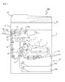
- Fig. 1 is a schematic structural view of an image forming apparatus 100 in which a document conveying device27 of the present disclosure is mounted.
- a document conveying device27 of the present disclosure when the image forming apparatus 100 (herein, a digital multifunction machine is shown as one example) performs a copying operation, an image reading device 6 reads image data on a document sheet and converts it into an image signal. Meanwhile, in an image forming portion 3 in a multifunction machine main body 2, while rotating in an A direction in Fig. 1 , a photosensitive drum 5 is uniformly charged by a charging unit 4.
- a developing unit 8 a developer (hereinafter, referred to as toner) is made to adhere to the electrostatic latent image, and thus a toner image is formed.
- Toner used here is supplied to the developing unit 8 from a toner container 9.
- a paper sheet is conveyed from a paper feeding mechanism 10 to the image forming portion3 via a paper sheet conveying path 11 and a registration roller pair 12, and in the image forming portion 3, the toner image on the surface of the photosensitive drum 5 is transferred onto the paper sheet by a transfer roller 13 (an image transfer portion). Then, the paper sheet onto which the toner image has been transferred is separated from the photosensitive drum 5 and conveyed to a fixing portion 14 having a fixing roller pair 14a, where the toner image is fixed.
- the paper sheet that has been passed through the fixing portion 14 is sent to a paper sheet conveying path 15 branching off in a plurality of directions, and a conveying direction thereof is set by path-switching mechanisms 21 and 22 that are provided at branching points in the paper sheet conveying path 15 and each have a plurality of path-switching guides.
- the paper sheet whose conveying direction has thus been set is ejected directly (or after having been sent to a reversing conveying path 16 and thus having undergone double-sided copying thereon) to a paper sheet ejection portion that is composed of a first ejection tray 17a and a second ejection tray 17b.
- the paper feeding mechanism 10 includes a plurality of paper feeding cassettes 10a and 10b that are demountably mounted in the multifunction machine main body 2 and in each of which paper sheets are housed and a stack bypass (manual feeding tray) 10c that is provided above the paper feeding cassettes 10a and 10b.
- the paper feeding cassettes 10a and 10b and the stack bypass 10c are linked to the image forming portion 3 that is composed of the photosensitive drum 5, the developing unit8, and so on by the paper sheet conveying path 11.
- a platen (document presser) 24 that holds under pressure a document sheet placed on a contact glass 25 (see Fig. 2 ) of the image reading device 6 is provided such that it can be opened and closed, and the document conveying device 27 is additionally provided over the platen 24.
- the paper sheet conveying path 15 is configured such that, on a downstream side of the fixing roller pair 14a, it first branches off right and left into two paths, one of which (in Fig. 1 , a path branched off to the right) communicates with the first ejection tray 17a.
- the other path (in Fig. 1 , a path branched off to the left) further branches off after passing through a conveying roller pair 19 into two paths, one of which (in Fig. 1 , a path extending straight to the left)communicates with the second ejection tray 17b.
- the other path (in Fig. 1 , a path branched off downward), on the other hand, communicates with the reversing conveying path 16.
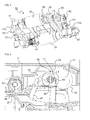
- Fig. 2 is a sectional side view showing an internal structure of the document conveying device 27.
- the document conveying device 27 has a document stacking tray 29 that is provided with a document guide 29a used to stack a plurality of document sheets such that they are aligned in a width direction thereof and a reversing tray 30 that is provided below the document stacking tray 29.
- the document stacking tray 29 and the reversing tray 30 are attached to a frame of the document conveying device 27.
- a cover member 31 is supported such that it can be opened and closed about one end of the frame (lower left in the figure) as a pivotal fulcrum, and on a lateral side of the cover member 31, a document ejection tray 32 is formed integrally with part of an upper surface of the platen 24 (see Fig. 1 ).
- a document conveying path d extending from the document stacking tray 29 up to the document ejection tray 32 is formed, and when the cover member 31 is opened, the document conveying path d is exposed so that a jam can be cleared.
- a document conveying section that is composed of a pickup roller 33, a feeding roller 34 with a separation roller 35, a registration roller pair 36, conveying roller pairs 37, 38, 39, and 40, a CIS roller 41, a reversing roller pair 42, an ejection roller pair 43, and so on.
- the pickup roller 33 is mounted to a swingable end of a unit frame body 51 that is supported swingably about a rotary shaft of the feeding roller 34 as a fulcrum.
- the pickup roller 33, the feeding roller 34, and the unit frame body 51 constitute a feeding unit 50 (see Fig. 3 ) that feeds document sheets.
- the unit frame body 51 is swung downward by rotation of the feeding roller 34 so that the feeding unit 50 is moved from a retracted position (home position) to a paper feeding position, where the pickup roller 33 is pressed against an upper surface of a stack of document sheets.
- the unit frame body 51 is swung upward by reverse rotation of the feeding roller 34 so that the feeding unit 50 is moved from the paper feeding position to the retracted position.
- the detailed configuration of the feeding unit 50 will be described later.
- the separation roller 35 is in contact from below with the feeding roller 34 under a predetermined pressure, thus constituting a document separation portion that conveys a document sheet one by one separately.
- the separation roller 35 has a built-in torque limiter so that, when a rotational load thereof falls below a predetermined torque value, its rotation is halted, and only when the rotational load thereof exceeds the predetermined torque value, it rotates by following rotation of the feeding roller 34.
- the contact glass 25 is composed of a manual document reading glass 25a and an automatic reading glass 25b and includes a white reference plate for correcting shading, which is disposed so as to be opposed to the automatic reading glass 25b (image reading position), and a document pressing portion (neither of these are shown) that lies above the white reference plate and is used to press the white reference plate toward the automatic reading glass 25b.
- the document conveying path d is curved along a length from the registration roller pair 36 up to the automatic reading glass 25b so as to cause reversing of a document sheet.
- a plurality of paper sheet detection sensors for detecting presence/absence or passage of a document sheet including a paper feeding sensor S1 and an ejection sensor S2, are provided at appropriate locations along the document conveying path d.
- a copying starting button on an operation panel of the image forming apparatus 100 is turned on, and thus a motor (not shown) starts rotating the feeding roller 34 and the pickup roller 33 in a paper feeding direction.
- the pickup roller 33 moves to the paper feeding position, so that an upper surface of the document sheets are pressed against the pickup roller 33 under a predetermined pressure (paper feeding pressure).
- the pickup roller 33 a plurality of upper ones of a stack of document sheets set on the document stacking tray 29 are sent to a nip portion between the feeding roller 34 and the separation roller 35. Then, only the uppermost one of the plurality of upper document sheets is separated from the rest by the separation roller 35 and is conveyed toward the registration roller pair 36. At this time, after the uppermost document sheet has been conveyed by a predetermined distance since detection of a tip end thereof by the paper feeding sensor S1, the rotary driving of the pickup roller 33 and the feeding roller 34 is halted, and thus primary paper feeding is completed. The document sheet that has been subjected to the primary paper feeding is stopped in a state where the tip end thereof is pressed against a nip portion of the registration roller pair 36 and a warp is formed at the tip end portion.
- the motor (not shown) operates to perform rotary driving of the registration roller pair 36, and thus secondary paper feeding is started.
- the registration roller pair 36, the conveying roller pairs 37 to 39, and the CIS roller 41 the document sheet is passed through the automatic reading glass 25b to be conveyed toward the ejection roller pair 43, after which, by the ejection roller pair 43, the document sheet is eventually ejected onto the document ejection tray 32.
- the ejection roller pair 43 based on detection of passage of a back end of the document sheet by the ejection sensor S2, it is detected that image reading of one document sheet has been completed.
- the ejection sensor S2 has a function of counting the number of document sheets upon every completion of conveying a document sheet, and as long as the paper feeding sensor S1 has detected a document sheet subsequent to the one that has just been conveyed, in a similar manner to the above, conveying of the second and subsequent document sheets is continuously performed.
- a document sheet is conveyed while being slightly pressed toward the automatic reading glass 25b so that an image on the document sheet is read by the image reading device 6 (see Fig. 1 ) through the automatic reading glass 25b.
- a one-step reading method an image on the rear side of the document sheet is read by a contact image sensor 49 provided so as to be opposed to the CIS roller 41, and an image on the front side of the document sheet is read through the automatic reading glass 25b.
- the document sheet is guided onto the reversing tray 30 by branching claws 47a, 47b, and 47c, and then the reversing roller pair 42 is reversely rotated to convey the document sheet with its rear side facing upward again to an upstream side of the registration roller pair 36so that an image on the rear side of the document sheet is read through the automatic reading glass 25b.
- Reading by use of the contact image sensor 49 while allowing a length of time required for reading to be reduced, results in poor image quality compared with a case of reading by use of the automatic reading glass 25b. For this reason, preferably, in a case of reading a text document or the like, the one-step reading method using the contact image sensor 49 is employed, and when high image quality and high definition reading is required as in a case of reading a photographic document or the like, the two-step reading method using the reversing tray 30 is employed.
- the document sheets ejected would be stacked with their front and rear sides reversed from the state of the document sheets when set on the document stacking tray 29.
- the document sheet is introduced again onto the reversing tray 30 by swinging the branching claws 47a to 47c and then is ejected onto the document ejection tray 32 via the conveying roller pair 40 and the ejection roller pair 43.
- FIG. 3 is a perspective view showing one embodiment of the feeding unit 50 and shows a state of the feeding unit 50 as seen from obliquely below.
- each of Figs. 4 and 5 is a fragmentary sectional view of the vicinity of the feeding unit 50 of the document conveying device 27, with Fig. 4 showing a state where the feeding unit 50 is at the retracted position, and Fig. 5 showing a state where the feeding unit 50 is at the paper feeding position.
- Fig. 6 is a partially enlarged view of the periphery of a contact area where an engagement piece 68 and a restriction surface 70 come in contact with each other, which are shown in Fig. 4
- Fig. 7 is a perspective view of the cover member 31 as seen from a rear surface side thereof. Based on Figs. 3 to 7 , and with reference to Figs. 1 and 2 where necessary, the following describes in detail a configuration of the feeding unit 50 and the periphery thereof.
- the feeding unit 50 is configured to include the unit frame body 51, the pickup roller 33 and the feeding roller 34 that are supported to the unit frame body 51, and a driving belt 55 that is used to rotate the pickup roller 33 and the feeding roller 34 together.
- the unit frame body 51 is made of a synthetic resin and includes side plates 51a and 51b paired in a width direction thereof.
- the feeding roller 34 is fixed on a longer first rotary shaft 57 that is provided to penetrate through between the side plates 51a and 51b of the unit frame body 51 on a base end side of the unit frame body 51 (on the left in Fig. 4 ).
- the first rotary shaft 57 is pivotably supported between a pair of side plates of the main body of the document conveying device 27.
- the pickup roller 33 is supported on a shorter second rotary shaft 58 that is pivotably supported between the side plates 51a and 51b of the unit frame body 51 on a swingable end side of the unit frame body 51 (on the right in Fig. 4 ).
- the feeding unit 50 is positioned at the feeding position where the pickup roller 33 is brought in press-contact with an upper surface of a stack of document sheets.
- the feeding unit 50 is positioned at the retracted position where the press-contact state of the pickup roller 33 with the document sheets is released.
- the pickup roller 33 is axially supported on the second rotary shaft 58 via a one-way clutch 60.
- the one-way clutch 60 is set so that rotation of the second rotary shaft 58 toward a predetermined direction (clockwise direction in Fig. 2 ) is transmitted to the pickup roller 33, while rotation of the second rotary shaft 58 toward a reverse direction is not transmitted thereto. This is to prevent the occurrence of a malfunction that the pickup roller 33 rotates in a reverse direction (counterclockwise direction in Fig. 2 ) around the second rotary shaft 58 to cause document sheets on the document stacking tray 29 to travel in a reverse direction.
- the driving belt 55 is looped over the first rotary shaft 57 and the second rotary shaft 58 and is configured to rotate by a driving force from the first rotary shaft 57. Furthermore, the first rotary shaft 57 and the second rotary shaft 58 are set to have an equal diameter in their respective areas where the driving belt 55 is looped, so that the pickup roller 33 and the feeding roller 34 rotate at equal rpm.
- a coil spring 61 that is loosely fitted on the first rotary shaft 57 is interposed in a compressed state.
- the unit frame body 51 when in a state where no external force is acting thereon, rotates integrally with the feeding roller 34about the first rotary shaft 57, whereas, by rotation of the unit frame body 51 in a direction toward the paper feeding position (clockwise direction in Fig. 4 ), the pickup roller 33 is brought in press-contact with a stack of document sheets on the document stacking tray 29.
- the feeding unit 50 when the feeding unit 50 is positionally set to the paper feeding position (see Fig.
- a stopper 63 is axially supported swingably around each of a pair of stopper spindles 65 that are provided to protrude outward from the side plates 51a and 51b of the unit frame body 51, respectively.
- the stopper spindle 65 is provided on an outer surface of each of the side plates 51a and 51b of the unit frame body 51 at a slightly upper position between the first rotary shaft 57 and the second rotary shaft 58 close to the secondary rotary shaft 58.
- the stopper 63 has a bearing portion 66 having a bearing hole 66a that is rotatably externally fitted on the stopper spindle 65, a document restriction portion 67 that extends from the bearing portion 66 to become opposed to tip ends of a stack of document sheets on the document stacking tray 29, and the engagement piece 68 that is provided to protrude from the bearing portion 66 in the opposite direction to the document restriction portion 67.
- the stopper 63 is swung about the stopper spindle 65 as a fulcrum and thus can be positionally changed between a position where the document restriction portion 67 sags down to be opposed to tip ends of document sheets on the document stacking tray 29 and a position where the document restriction portion 67 is retracted from the tip ends of the document sheets.
- a unit disposition portion 31a in which the feeding unit 50 is disposed, and in the unit disposition portion 31a, a rib 71 having the restriction surface 70 at a position opposed to the engagement piece 68 of the stopper 63 is provided to protrude.
- the restriction surface 70 extends downward from a position coinciding with a trajectory (indicated by a broken line L1 in Fig. 4 ; hereinafter, referred to as a first trajectory L1), along which the engagement piece 68 moves as the stopper 63 is swung about the stopper spindle 65 (second swinging fulcrum),toward the inner side of the first trajectory L1.
- the document restriction portion 67 is in a state where its swinging in the clockwise direction is inhibited. Hence, even when a stack of document sheets are placed on the document stacking tray 29, and tip ends thereof are pressed against the document restriction portion 67, the document restriction portion 67 stays locked in position. Thus, by pressing a stack of document sheets against a pair of the document restriction portions 67, tip ends of the stack of document sheets can be reliably aligned with each other.
- the feeding roller 34 is rotated to swing the unit frame body 51 in the clockwise direction, and thus the feeding unit 50 is moved from the retracted position to the paper feeding position.
- the engagement piece 68 slides downward along the restriction surface 70, so that the stopper 63, while being slightly swung in the counterclockwise direction in Fig. 4 , moves downward together with the feeding unit 50.
- the stopper 63 is brought into the fixing released state.
- the feeding unit 50 is positionally set to the paper feeding position, and thus the stopper 63 is in the fixing released state (see Fig. 5 )
- the pickup roller 33 is driven to rotate in the clockwise direction around the second rotary shaft 58, by the pickup roller 33, the uppermost one or a plurality of upper ones of document sheets are guided to be drawn in to a downstream side.
- the document restriction portion 67 By a tip end(s) of the document sheet(s) drawn in, the document restriction portion 67 is pushed to be swung in the clockwise direction about the stopper spindle 65 as the fulcrum and then is pushed further, thus causing the document sheet(s) to slip through a lower end edge of the document restriction portion 67 to be introduced into the nip portion between the feeding roller 34 and the separation roller 35.
- the feeding roller 34 is reversely rotated to swing the unit frame body 51 in the counterclockwise direction, and thus the feeding unit 50 is moved from the paper feeding position to the retracted position.
- the stopper 63 is swung in the counterclockwise direction in Fig. 5 , so that interference between the engagement piece 68 and the restriction surface 70 is avoided.
- the engagement piece 68 is again engaged with the restriction surface 70, and thus the stopper 63 is brought into the opposedly fixed state.
- the restriction surface 70 extends downward from a position coinciding with a trajectory (indicated by an alternate long and short dashed line L2 in Figs. 4 and 6 ; hereinafter, referred to as a second trajectory L2), along which the engagement piece 68 moves as the feeding unit 50 is swung about the first rotary shaft 57 (first swinging fulcrum), toward the inner side of the second trajectory L2.
- a trajectory indicated by an alternate long and short dashed line L2 in Figs. 4 and 6 ; hereinafter, referred to as a second trajectory L2
- a maximum value d1 of a gap between an inner peripheral surface of the bearing hole 66a of the stopper 63 and an outer peripheral surface of the stopper spindle 65 is set to be larger than a maximum value d2 of a length by which the restriction surface 70 protrudes to the inner side of the second trajectory L2.
- the inner diameter of the bearing hole 66a is set to 6.55 mm
- the diameter of the stopper spindle 65 is set to 5.96 mm, so that d1 and d2 are 0.59 mm and 0.28 mm, respectively.
- the stopper 63 in moving the feeding unit 50 from the retracted position to the paper feeding position, the stopper 63 is permitted a movement by a distance defined by the gap d1 in a direction away from the restriction surface 70, and thus interference between the engagement piece 68 and the restriction surface 70 can be avoided.
- the feeding unit 50 can be moved smoothly from the retracted position to the paper feeding position.
- the present disclosure is not limited to the above-described embodiment and may be variously embodied without departing from the spirit of the present disclosure.
- the driving mechanism of the feeding unit 50 shown in Fig. 3 is merely one example, and it is possible to use a gear mechanism in place of the driving belt 55.
- other parts of the document conveying device 27 also can be arbitrarily modified in design.
- a paper feeding belt may be used in place of the feeding roller 34, and a separation pad may be used in place of the separation roller 35.
- the present disclosure is applicable to a document conveying device that conveys a document sheet one by one separately from a stack of document sheets.
- a low-cost document conveying device with a simple structure can be provided, in which, in setting a stack of document sheets, undesired swinging of a stopper is restricted, so that the stack of document sheets can be reliably set, and that can prevent a phenomenon that tip ends of the stack of document sheets are accidentally brought to reach as far as the vicinity of a document separation portion, leading to the occurrence of double feeding or skew feeding of document sheets.
Abstract
Description
- The present disclosure relates to a document conveying device that is mounted in an image forming apparatus such as a digital copy machine, a laser printer, or the like and feeds a document sheet one by one separately from a stack of document sheets, and to an image forming apparatus including the same.
- Conventional image reading devices that are mounted in copy machines and so on utilizing the electrophotographic process may include a document conveying device (automatic document feeder) that sequentially feeds a document in sheet form onto a document placing table in order for it to be read and removes it from the document placing table after it has been read. An image reading device of this type is capable of performing the following two reading methods. One is a sheet-through method in which, with a document presser closed, a document sheet is read while being automatically conveyed by a document conveying device, and the other is a document stationary method in which, upon every completion of reading, the document presser is opened and closed in order for a document sheet on the document placing table (contact glass) to be replaced one by one.
- In the former, namely, the sheet-through method, a document reading operation is performed with an optical system in the image reading device held at a predetermined image reading position without performing a scanning movement, whereas in the latter, namely, the document stationary method, a reading operation is performed while the optical system performs a scanning movement. In reading a document sheet based on the sheet-through method, generally, a pickup roller supported in a feeding unit is brought in press-contact with an uppermost surface of a stack of document sheets stacked on a document stacking tray, and the document sheet is conveyed in that state.
- Typically, when a stack of document sheets are placed on the document stacking tray, by a manual operation, tip ends of the stack of document sheets in a feeding direction are made to butt against a predetermined butting member (stopper) provided in the feeding unit, and the tip ends of the stack of document sheets are thereby aligned with each other. The stopper is configured to be changeable between an opposedly fixed state where it is fixed so as to be opposed to a stack of document sheets on the document stacking tray and a fixing released state where it is swung so that the opposedly fixed state is released to allow passage of document sheets therethrough. For aligning tip ends of a stack of document sheets on the document stacking tray with each other, the stopper is set to be in the opposedly fixed state, while for feeding a document sheet one by one from the stack of document sheets by driving the feeding unit including the pickup roller and a feeding roller, the stopper is set to be in the fixing released state.
- By the way, when, in setting a stack of document sheets on the document stacking tray, a user align send portions of the stack of document sheets with each other by use of the stopper, vibrations might occur to cause the feeding unit disposed at a standby position to be displaced downward, which has been problematic.
- In order to prevent this trouble, there is known an automatic paper sheet feeding device that includes a stopper having a stopper piece that, from a support shaft supported in a support body (feeding unit) in which a pickup roller is supported, extends downward to become opposed to tip ends of paper sheets on a feeding tray and an engagement piece that is provided to protrude upward from the support shaft, and in which a restriction surface that restricts swinging of the stopper, which has been set to be in the opposedly fixed state, by being engaged with the engagement piece is provided on a main body side of the device.
- In the above-described configuration, the engagement piece of the stopper and the restriction surface provided on the main body side of the device interfere with each other and thus can prevent the stopper from being brought into the fixing released state. With this configuration, however, for example, in a case where various parts of the document conveying device are driven by use of one motor, members to be driven including the feeding unit are each connected to the motor via a clutch.
- In such a case, since the feeding unit is not always connected to be driven, there has been the following problem. That is, when, in setting a stack of document sheets, a user forcibly pushes in the stack of document sheets toward the stopper, a load in a document feeding direction is applied to the stopper, so that a force in a downward direction is exerted on the feeding unit in which the stopper is supported. As a result, the feeding unit might be displaced downward below a standby position thereof, causing the stopper, which has been set to be in the opposedly fixed state, to be brought into the fixing released state. Because of this, tip ends of the stack of document sheets accidentally reach as far as the vicinity of a nip portion (document separation portion) of a feeding roller pair, leading to the occurrence of double feeding or skew feeding of document sheets.
- It is an object of the present disclosure to provide a document conveying device that, even when an excessive pressure is applied to a stopper used to align tip ends of a stack of document sheets with each other, prevents positional displacement of the stopper and a feeding unit in which the stopper is supported and thus is capable of performing a stable operation, and an image forming apparatus including the same.
- A document conveying device according to one aspect of the present disclosure includes a document stacking tray, a feeding unit, a stopper, and a restriction surface. On the document stacking tray, a plurality of document sheets are stacked. The feeding unit has a unit frame body that is swingably supported, at an end portion thereof on a downstream side in a document conveying direction, on a first swinging fulcrum on a main body side of the document conveying device, and a pickup roller that is rotatably supported on a swingable end side of the unit frame body. The feeding unit is disposed selectively at a paper feeding position where the pickup roller is brought in press-contact with an upper surface of a stack of document sheets stacked on the document stacking tray or at a retracted position where the upper surface of the stack of document sheets and the pickup roller are separated by a predetermined distance from each other. The stopper is swingably supported on a second swinging fulcrum provided on the swingable end side of the unit frame body, and has a document restriction portion that extends from the second swinging fulcrum to become opposed to tip ends of the stack of document sheets stacked on the document stacking tray and an engagement piece that is provided to protrude from the second swinging fulcrum in the opposite direction to the document restriction portion. The restriction surface is provided on the main body side of the document conveying device and extends downward from a position coinciding with a first trajectory, along which the engagement piece moves as the stopper is swung about the second swinging fulcrum, toward the inner side of the first trajectory. When the feeding unit is at the retracted position, the engagement piece is engaged with the restriction surface, so that the document restriction portion is brought into a position opposed to the tip ends of the stack of document sheets, and thus an opposedly fixed state is brought about where swinging of the stopper is restricted. When the feeding unit is at the paper feeding position, the engagement between the engagement piece and the restriction surface is released, and thus a fixing released state is brought about where the swinging of the stopper is allowed. The restriction surface extends downward from a position coinciding with a second trajectory, along which the engagement piece moves as the feeding unit is swung about the first swinging fulcrum, toward the inner side of the second trajectory.
- Still other objects of the present disclosure and specific advantages provided by the present disclosure will be made further apparent from the following description of an embodiment.
-
-
Fig. 1 is a sectional side view showing an entire configuration of animage forming apparatus 100 in which adocument conveying device 27 of the present disclosure is mounted. -
Fig. 2 is a sectional side view showing an internal structure of thedocument conveying device 27 according to one embodiment of the present disclosure. -
Fig. 3 is a perspective view of afeeding unit 50 used in thedocument conveying device 27 of the present disclosure, as seen from obliquely below. -
Fig. 4 is a fragmentary sectional view of the vicinity of thefeeding unit 50 of thedocument conveying device 27, which shows a state where thefeeding unit 50 is at a retracted position. -
Fig. 5 is a fragmentary sectional view of the vicinity of thefeeding unit 50 of thedocument conveying device 27, which shows a state in which thefeeding unit 50 is at a paper feeding position. -
Fig. 6 is a partially enlarged view of the periphery of a contact area where anengagement piece 68 and arestriction surface 70 come in contact with each other, which is shown inFig. 4 . -
Fig. 7 is a perspective view of acover member 31 of thedocument conveying device 27, as seen from a rear surface side thereof. - The following describes an embodiment of the present disclosure with reference to the appended drawings.
Fig. 1 is a schematic structural view of animage forming apparatus 100 in which a document conveying device27 of the present disclosure is mounted. InFig. 1 , when the image forming apparatus 100 (herein, a digital multifunction machine is shown as one example) performs a copying operation, animage reading device 6 reads image data on a document sheet and converts it into an image signal. Meanwhile, in animage forming portion 3 in a multifunction machinemain body 2, while rotating in an A direction inFig. 1 , a photosensitive drum 5 is uniformly charged by a charging unit 4. By a laser beam from an exposure unit (a laser scanning unit or the like) 7, which is based on the document image data read in theimage reading device 6, an electrostatic latent image is formed on the photosensitive drum 5. After that, by a developingunit 8, a developer (hereinafter, referred to as toner) is made to adhere to the electrostatic latent image, and thus a toner image is formed. Toner used here is supplied to the developingunit 8 from a toner container 9. - Toward the photosensitive drum 5 on which the toner image has been formed as described above, a paper sheet is conveyed from a
paper feeding mechanism 10 to the image forming portion3 via a papersheet conveying path 11 and aregistration roller pair 12, and in theimage forming portion 3, the toner image on the surface of the photosensitive drum 5 is transferred onto the paper sheet by a transfer roller 13 (an image transfer portion). Then, the paper sheet onto which the toner image has been transferred is separated from the photosensitive drum 5 and conveyed to afixing portion 14 having afixing roller pair 14a, where the toner image is fixed. The paper sheet that has been passed through thefixing portion 14 is sent to a papersheet conveying path 15 branching off in a plurality of directions, and a conveying direction thereof is set by path-switching mechanisms sheet conveying path 15 and each have a plurality of path-switching guides. The paper sheet whose conveying direction has thus been set is ejected directly (or after having been sent to a reversingconveying path 16 and thus having undergone double-sided copying thereon) to a paper sheet ejection portion that is composed of afirst ejection tray 17a and asecond ejection tray 17b. - Furthermore, though not shown, a static eliminator that eliminates residual electric charge on the surface of the photosensitive drum 5 is provided on a downstream side of a
cleaner 18. Moreover, thepaper feeding mechanism 10 includes a plurality ofpaper feeding cassettes main body 2 and in each of which paper sheets are housed and a stack bypass (manual feeding tray) 10c that is provided above thepaper feeding cassettes paper feeding cassettes stack bypass 10c are linked to theimage forming portion 3 that is composed of the photosensitive drum 5, the developing unit8, and so on by the papersheet conveying path 11. On an upper surface of the multifunction machinemain body 2, a platen (document presser) 24 that holds under pressure a document sheet placed on a contact glass 25 (seeFig. 2 ) of theimage reading device 6 is provided such that it can be opened and closed, and thedocument conveying device 27 is additionally provided over theplaten 24. - Specifically, the paper
sheet conveying path 15 is configured such that, on a downstream side of thefixing roller pair 14a, it first branches off right and left into two paths, one of which (inFig. 1 , a path branched off to the right) communicates with thefirst ejection tray 17a. The other path (inFig. 1 , a path branched off to the left) further branches off after passing through aconveying roller pair 19 into two paths, one of which (inFig. 1 , a path extending straight to the left)communicates with thesecond ejection tray 17b. The other path (inFig. 1 , a path branched off downward), on the other hand, communicates with the reversingconveying path 16. -
Fig. 2 is a sectional side view showing an internal structure of thedocument conveying device 27. Thedocument conveying device 27 has adocument stacking tray 29 that is provided with adocument guide 29a used to stack a plurality of document sheets such that they are aligned in a width direction thereof and areversing tray 30 that is provided below thedocument stacking tray 29. Thedocument stacking tray 29 and the reversingtray 30 are attached to a frame of thedocument conveying device 27. Furthermore, with respect to the frame of thedocument conveying device 27, acover member 31 is supported such that it can be opened and closed about one end of the frame (lower left in the figure) as a pivotal fulcrum, and on a lateral side of thecover member 31, adocument ejection tray 32 is formed integrally with part of an upper surface of the platen 24 (seeFig. 1 ). In thecover member 31, a document conveying path d extending from thedocument stacking tray 29 up to thedocument ejection tray 32 is formed, and when thecover member 31 is opened, the document conveying path d is exposed so that a jam can be cleared. - In the
cover member 31, there is provided, along the document conveying path d, a document conveying section that is composed of apickup roller 33, afeeding roller 34 with aseparation roller 35, aregistration roller pair 36, conveyingroller pairs CIS roller 41, a reversingroller pair 42, anejection roller pair 43, and so on. - The
pickup roller 33 is mounted to a swingable end of aunit frame body 51 that is supported swingably about a rotary shaft of thefeeding roller 34 as a fulcrum. Thepickup roller 33, thefeeding roller 34, and theunit frame body 51 constitute a feeding unit 50 (seeFig. 3 ) that feeds document sheets. In a document feeding process, theunit frame body 51 is swung downward by rotation of the feedingroller 34 so that thefeeding unit 50 is moved from a retracted position (home position) to a paper feeding position, where thepickup roller 33 is pressed against an upper surface of a stack of document sheets. On the other hand, after completion of the document feeding process, theunit frame body 51 is swung upward by reverse rotation of the feedingroller 34 so that thefeeding unit 50 is moved from the paper feeding position to the retracted position. The detailed configuration of thefeeding unit 50 will be described later. - The
separation roller 35 is in contact from below with the feedingroller 34 under a predetermined pressure, thus constituting a document separation portion that conveys a document sheet one by one separately. Theseparation roller 35 has a built-in torque limiter so that, when a rotational load thereof falls below a predetermined torque value, its rotation is halted, and only when the rotational load thereof exceeds the predetermined torque value, it rotates by following rotation of the feedingroller 34. - The
contact glass 25 is composed of a manualdocument reading glass 25a and anautomatic reading glass 25b and includes a white reference plate for correcting shading, which is disposed so as to be opposed to theautomatic reading glass 25b (image reading position), and a document pressing portion (neither of these are shown) that lies above the white reference plate and is used to press the white reference plate toward theautomatic reading glass 25b. The document conveying path d is curved along a length from theregistration roller pair 36 up to theautomatic reading glass 25b so as to cause reversing of a document sheet. Furthermore, a plurality of paper sheet detection sensors for detecting presence/absence or passage of a document sheet, including a paper feeding sensor S1 and an ejection sensor S2, are provided at appropriate locations along the document conveying path d. - Next, a description is given of a document conveying operation based on the sheet-through method that is performed using the
document conveying device 27. First, with reference toFig. 2 , there is described a case of reading a one-sided document sheet. After a plurality of document sheets are set on thedocument stacking tray 29 such that image sides thereof face upward, a copying starting button on an operation panel of theimage forming apparatus 100 is turned on, and thus a motor (not shown) starts rotating the feedingroller 34 and thepickup roller 33 in a paper feeding direction. Moreover, thepickup roller 33 moves to the paper feeding position, so that an upper surface of the document sheets are pressed against thepickup roller 33 under a predetermined pressure (paper feeding pressure). - Typically, by the
pickup roller 33,a plurality of upper ones of a stack of document sheets set on thedocument stacking tray 29 are sent to a nip portion between the feedingroller 34 and theseparation roller 35. Then, only the uppermost one of the plurality of upper document sheets is separated from the rest by theseparation roller 35 and is conveyed toward theregistration roller pair 36. At this time, after the uppermost document sheet has been conveyed by a predetermined distance since detection of a tip end thereof by the paper feeding sensor S1, the rotary driving of thepickup roller 33 and the feedingroller 34 is halted, and thus primary paper feeding is completed. The document sheet that has been subjected to the primary paper feeding is stopped in a state where the tip end thereof is pressed against a nip portion of theregistration roller pair 36 and a warp is formed at the tip end portion. - After a lapse of a predetermined length of time from the completion of the primary paper feeding, the motor (not shown) operates to perform rotary driving of the
registration roller pair 36, and thus secondary paper feeding is started. By theregistration roller pair 36, the conveying roller pairs 37 to 39, and theCIS roller 41, the document sheet is passed through theautomatic reading glass 25b to be conveyed toward theejection roller pair 43, after which, by theejection roller pair 43, the document sheet is eventually ejected onto thedocument ejection tray 32. At this time, based on detection of passage of a back end of the document sheet by the ejection sensor S2, it is detected that image reading of one document sheet has been completed. - Herein, the ejection sensor S2 has a function of counting the number of document sheets upon every completion of conveying a document sheet, and as long as the paper feeding sensor S1 has detected a document sheet subsequent to the one that has just been conveyed, in a similar manner to the above, conveying of the second and subsequent document sheets is continuously performed. When being passed through the
automatic reading glass 25b, a document sheet is conveyed while being slightly pressed toward theautomatic reading glass 25b so that an image on the document sheet is read by the image reading device 6 (seeFig. 1 ) through theautomatic reading glass 25b. - Furthermore, in a case of reading a double-sided document sheet, there are used a one-step reading method and a two-step reading method. In the one-step reading method, an image on the rear side of the document sheet is read by a
contact image sensor 49 provided so as to be opposed to theCIS roller 41, and an image on the front side of the document sheet is read through theautomatic reading glass 25b. In the two-step reading method, after an image on the front side of the document sheet has been read by theautomatic reading glass 25b, the document sheet is guided onto the reversingtray 30 by branchingclaws roller pair 42 is reversely rotated to convey the document sheet with its rear side facing upward again to an upstream side of the registration roller pair 36so that an image on the rear side of the document sheet is read through theautomatic reading glass 25b. - Reading by use of the
contact image sensor 49, while allowing a length of time required for reading to be reduced, results in poor image quality compared with a case of reading by use of theautomatic reading glass 25b. For this reason, preferably, in a case of reading a text document or the like, the one-step reading method using thecontact image sensor 49 is employed, and when high image quality and high definition reading is required as in a case of reading a photographic document or the like, the two-step reading method using the reversingtray 30 is employed. - In a case where the two-step reading method is employed, if document sheets that have been read were sequentially ejected directly onto the
document ejection tray 32, the document sheets ejected would be stacked with their front and rear sides reversed from the state of the document sheets when set on thedocument stacking tray 29. In order to avoid this, after an image on the rear side of a document sheet has been read through theautomatic reading glass 25b, the document sheet is introduced again onto the reversingtray 30 by swinging the branchingclaws 47a to 47c and then is ejected onto thedocument ejection tray 32 via the conveyingroller pair 40 and theejection roller pair 43. By this configuration, before document sheets are ejected, front and rear sides thereof are again reversed, and thus the document sheets can be stacked on thedocument ejection tray 32 while maintaining the state of the document sheets when set on thedocument stacking tray 29. -
Fig. 3 is a perspective view showing one embodiment of thefeeding unit 50 and shows a state of thefeeding unit 50 as seen from obliquely below. Furthermore, each ofFigs. 4 and5 is a fragmentary sectional view of the vicinity of thefeeding unit 50 of thedocument conveying device 27, withFig. 4 showing a state where thefeeding unit 50 is at the retracted position, andFig. 5 showing a state where thefeeding unit 50 is at the paper feeding position.Fig. 6 is a partially enlarged view of the periphery of a contact area where anengagement piece 68 and arestriction surface 70 come in contact with each other, which are shown inFig. 4 , andFig. 7 is a perspective view of thecover member 31 as seen from a rear surface side thereof. Based onFigs. 3 to 7 , and with reference toFigs. 1 and2 where necessary, the following describes in detail a configuration of thefeeding unit 50 and the periphery thereof. - As shown in
Fig. 3 , thefeeding unit 50 is configured to include theunit frame body 51, thepickup roller 33 and the feedingroller 34 that are supported to theunit frame body 51, and a drivingbelt 55 that is used to rotate thepickup roller 33 and the feedingroller 34 together. In this embodiment, theunit frame body 51 is made of a synthetic resin and includesside plates - The feeding
roller 34 is fixed on a longer firstrotary shaft 57 that is provided to penetrate through between theside plates unit frame body 51 on a base end side of the unit frame body 51 (on the left inFig. 4 ). The firstrotary shaft 57 is pivotably supported between a pair of side plates of the main body of thedocument conveying device 27. - The
pickup roller 33 is supported on a shorter secondrotary shaft 58 that is pivotably supported between theside plates unit frame body 51 on a swingable end side of the unit frame body 51 (on the right inFig. 4 ). By swinging of theunit frame body 51 in the clockwise direction inFig. 2 about the firstrotary shaft 57 as a swinging fulcrum, thefeeding unit 50 is positioned at the feeding position where thepickup roller 33 is brought in press-contact with an upper surface of a stack of document sheets. Furthermore, by swinging of theunit frame body 51 in a reverse direction, thefeeding unit 50 is positioned at the retracted position where the press-contact state of thepickup roller 33 with the document sheets is released. - The
pickup roller 33 is axially supported on the secondrotary shaft 58 via a one-way clutch 60. The one-way clutch 60 is set so that rotation of the secondrotary shaft 58 toward a predetermined direction (clockwise direction inFig. 2 ) is transmitted to thepickup roller 33, while rotation of the secondrotary shaft 58 toward a reverse direction is not transmitted thereto. This is to prevent the occurrence of a malfunction that thepickup roller 33 rotates in a reverse direction (counterclockwise direction inFig. 2 ) around the secondrotary shaft 58 to cause document sheets on thedocument stacking tray 29 to travel in a reverse direction. - The driving
belt 55 is looped over the firstrotary shaft 57 and the secondrotary shaft 58 and is configured to rotate by a driving force from the firstrotary shaft 57. Furthermore, the firstrotary shaft 57 and the secondrotary shaft 58 are set to have an equal diameter in their respective areas where the drivingbelt 55 is looped, so that thepickup roller 33 and the feedingroller 34 rotate at equal rpm. - Between an end face of the feeding
roller 34 on the opposite side to the drivingbelt 55 and theside plate 51a of theunit frame body 51, which is opposed to this end face, acoil spring 61 that is loosely fitted on the firstrotary shaft 57 is interposed in a compressed state. By this configuration, rotation of the feedingroller 34 is transmitted to theunit frame body 51 by friction forces generated between thecoil spring 61 and the end face of the feedingroller 34 and between thecoil spring 61 and an inner surface of theside plate 51a. - Thus, the
unit frame body 51, when in a state where no external force is acting thereon, rotates integrally with the feeding roller 34about the firstrotary shaft 57, whereas, by rotation of theunit frame body 51 in a direction toward the paper feeding position (clockwise direction inFig. 4 ), thepickup roller 33 is brought in press-contact with a stack of document sheets on thedocument stacking tray 29. By this configuration, when thefeeding unit 50 is positionally set to the paper feeding position (seeFig. 5 ), due to a friction force between the end surface of the feedingroller 34 and theside plate 51a of theunit frame body 51, a large rotational force is imparted to the feedingroller 34, and thus a state is brought about where while rotation of the feedingroller 34 is continued, rotation of theunit frame body 51 is restricted. - On the contrary, when, by rotation of the
unit frame body 51 in a direction toward the retracted position (counterclockwise direction inFig. 4 ), theunit frame body 51 comes in contact with a top surface of thecover member 31, and thus thefeeding unit 50 is positionally set to the retracted position (seeFig. 4 ), a state is brought about where while rotation of the feedingroller 43 toward the counterclockwise direction is continued, rotation of theunit frame body 51 is restricted. - A
stopper 63 is axially supported swingably around each of a pair ofstopper spindles 65 that are provided to protrude outward from theside plates unit frame body 51, respectively. Thestopper spindle 65 is provided on an outer surface of each of theside plates unit frame body 51 at a slightly upper position between the firstrotary shaft 57 and the secondrotary shaft 58 close to the secondaryrotary shaft 58. - The
stopper 63 has a bearingportion 66 having abearing hole 66a that is rotatably externally fitted on thestopper spindle 65, adocument restriction portion 67 that extends from the bearingportion 66 to become opposed to tip ends of a stack of document sheets on thedocument stacking tray 29, and theengagement piece 68 that is provided to protrude from the bearingportion 66 in the opposite direction to thedocument restriction portion 67. Thestopper 63 is swung about thestopper spindle 65 as a fulcrum and thus can be positionally changed between a position where thedocument restriction portion 67 sags down to be opposed to tip ends of document sheets on thedocument stacking tray 29 and a position where thedocument restriction portion 67 is retracted from the tip ends of the document sheets. - As shown in
Fig. 7 , on the rear surface side of thecover member 31, there is formed aunit disposition portion 31a in which thefeeding unit 50 is disposed, and in theunit disposition portion 31a, arib 71 having therestriction surface 70 at a position opposed to theengagement piece 68 of thestopper 63 is provided to protrude. Therestriction surface 70 extends downward from a position coinciding with a trajectory (indicated by a broken line L1 inFig. 4 ; hereinafter, referred to as a first trajectory L1), along which theengagement piece 68 moves as thestopper 63 is swung about the stopper spindle 65 (second swinging fulcrum),toward the inner side of the first trajectory L1. - When the
feeding unit 50 is swung about the firstrotary shaft 57 as a fulcrum such that it is positionally set to the retracted position shown inFig. 4 , theengagement piece 68 comes in contact with therestriction surface 70,so that thedocument restriction portion 67 is brought into a position opposed to tip ends of a stack of document sheets, and thus a state (opposedly fixed state) is brought about where swinging of thestopper 63 is restricted. On the other hand, when thefeeding unit 50, which has been positionally set to the retracted position, is swung in the clockwise direction about the firstrotary shaft 57 as the fulcrum such that it is positionally set to the paper feeding position shown inFig. 5 , the contact state of theengagement piece 68 with therestriction surface 70 is released, and thus a state (fixing released state) is brought about where swinging of thestopper 63 is allowed. - That is, in a case where the
feeding unit 50 is positionally set to the retracted position, and thus the stopper 63is in the opposedly fixed state (seeFig. 4 ), thedocument restriction portion 67 is in a state where its swinging in the clockwise direction is inhibited. Hence, even when a stack of document sheets are placed on thedocument stacking tray 29, and tip ends thereof are pressed against thedocument restriction portion 67, thedocument restriction portion 67 stays locked in position. Thus, by pressing a stack of document sheets against a pair of thedocument restriction portions 67, tip ends of the stack of document sheets can be reliably aligned with each other. - In a document conveying process, the feeding
roller 34 is rotated to swing theunit frame body 51 in the clockwise direction, and thus thefeeding unit 50 is moved from the retracted position to the paper feeding position. At this time, theengagement piece 68 slides downward along therestriction surface 70, so that thestopper 63, while being slightly swung in the counterclockwise direction inFig. 4 , moves downward together with thefeeding unit 50. When theengagement piece 68 becomes detached from therestriction surface 70, thestopper 63 is brought into the fixing released state. - Furthermore, in a case where the
feeding unit 50 is positionally set to the paper feeding position, and thus thestopper 63 is in the fixing released state (seeFig. 5 ),when thepickup roller 33 is driven to rotate in the clockwise direction around the secondrotary shaft 58, by thepickup roller 33, the uppermost one or a plurality of upper ones of document sheets are guided to be drawn in to a downstream side. By a tip end(s) of the document sheet(s) drawn in, thedocument restriction portion 67 is pushed to be swung in the clockwise direction about thestopper spindle 65 as the fulcrum and then is pushed further, thus causing the document sheet(s) to slip through a lower end edge of thedocument restriction portion 67 to be introduced into the nip portion between the feedingroller 34 and theseparation roller 35. - Furthermore, after completion of the document conveying process, the feeding
roller 34 is reversely rotated to swing theunit frame body 51 in the counterclockwise direction, and thus thefeeding unit 50 is moved from the paper feeding position to the retracted position. At this time, under the self-weight of thedocument restriction portion 67, thestopper 63 is swung in the counterclockwise direction inFig. 5 , so that interference between theengagement piece 68 and therestriction surface 70 is avoided. When thefeeding unit 50 becomes disposed at the retracted position, as shown inFig. 4 , theengagement piece 68 is again engaged with therestriction surface 70, and thus thestopper 63 is brought into the opposedly fixed state. - In the
document conveying device 27 of this embodiment, as shown inFig. 6 , therestriction surface 70 extends downward from a position coinciding with a trajectory (indicated by an alternate long and short dashed line L2 inFigs. 4 and6 ; hereinafter, referred to as a second trajectory L2), along which theengagement piece 68 moves as thefeeding unit 50 is swung about the first rotary shaft 57 (first swinging fulcrum), toward the inner side of the second trajectory L2. - According to this configuration, in a case where, when a stack of document sheets are set on the
document stacking tray 29, tip ends of the stack of document sheets are pressed strongly against thedocument restriction portion 67 of thestopper 63 in the opposedly fixed state, thus exerting a force that acts to swing theunit frame body 51 in the clockwise direction (downward) inFig. 4 , since therestriction surface 70 extending to the inner side of the second trajectory L2 and theengagement piece 68 come in contact with each other, a downward movement of theunit frame body 51 is restricted. - As a result, when a stack of document sheets are pressed against the
document restriction portion 67 so that their tip ends are aligned with each other, a downward displacement of thefeeding unit 50 from the retracted position and swinging of thedocument restriction portion 67 caused thereby can be avoided. This can prevent a phenomenon that, in setting a stack of document sheets, tip ends of the stack of document sheets are accidentally bought to reach as far as the vicinity of the nip portion between the feedingroller 34 and theseparation roller 35, leading to the occurrence of double feeding or skew feeding of document sheets. - Furthermore, preferably, a maximum value d1 of a gap between an inner peripheral surface of the
bearing hole 66a of thestopper 63 and an outer peripheral surface of thestopper spindle 65 is set to be larger than a maximum value d2 of a length by which therestriction surface 70 protrudes to the inner side of the second trajectory L2. In this embodiment, the inner diameter of thebearing hole 66a is set to 6.55 mm, and the diameter of thestopper spindle 65 is set to 5.96 mm, so that d1 and d2 are 0.59 mm and 0.28 mm, respectively. - By this configuration, in moving the
feeding unit 50 from the retracted position to the paper feeding position, thestopper 63 is permitted a movement by a distance defined by the gap d1 in a direction away from therestriction surface 70, and thus interference between theengagement piece 68 and therestriction surface 70 can be avoided. Thus, thefeeding unit 50 can be moved smoothly from the retracted position to the paper feeding position. - The present disclosure is not limited to the above-described embodiment and may be variously embodied without departing from the spirit of the present disclosure. For example, the driving mechanism of the
feeding unit 50 shown inFig. 3 is merely one example, and it is possible to use a gear mechanism in place of the drivingbelt 55. Furthermore, other parts of thedocument conveying device 27 also can be arbitrarily modified in design. For example, a paper feeding belt may be used in place of the feedingroller 34, and a separation pad may be used in place of theseparation roller 35. - The present disclosure is applicable to a document conveying device that conveys a document sheet one by one separately from a stack of document sheets. With the use of the present disclosure, a low-cost document conveying device with a simple structure can be provided, in which, in setting a stack of document sheets, undesired swinging of a stopper is restricted, so that the stack of document sheets can be reliably set, and that can prevent a phenomenon that tip ends of the stack of document sheets are accidentally brought to reach as far as the vicinity of a document separation portion, leading to the occurrence of double feeding or skew feeding of document sheets.
The above embodiments of the invention as well as the appended claims and figures show multiple characterizing features of the invention in specific combinations. The skilled person will easily be able to consider further combinations or sub-combinations of these features in order to adapt the invention as defined in the claims to his specific needs.
Claims (4)
- A document conveying device (27), comprising:a document stacking tray(29) on which a plurality of document sheets are stacked;a feeding unit (50) that has a unit frame body (51) that is swingably supported, at an end portion thereof on a downstream side in a document conveying direction, on a first swinging fulcrum (57) on a main body side of the document conveying device (27), and a pickup roller (33) that is rotatably supported on a swingable end side of the unit frame body (51), and is disposed selectively at a paper feeding position where the pickup roller (33) is brought in press-contact with an upper surface of a stack of document sheets stacked on the document stacking tray (29) or at a retracted position where the upper surface of the stack of document sheets and the pickup roller (33) are separated by a predetermined distance from each other;a stopper (63) that is swingably supported on a second swinging fulcrum (65, 66a) provided on the swingable end side of the unit frame body (51), and has a document restriction portion (67) that extends from the second swinging fulcrum (65, 66a) to become opposed to tip ends of the stack of document sheets stacked on the document stacking tray (29) and an engagement piece (68) that is provided to protrude from the second swinging fulcrum (65, 66a) in an opposite direction to the document restriction portion (67); anda restriction surface(70) that is provided on the main body side of the document conveying device (27) and extends downward from a position coinciding with a first trajectory, along which the engagement piece (68) moves as the stopper (63) is swung about the second swinging fulcrum (65, 66a), toward an inner side of the first trajectory,wherein when the feeding unit (50) is at the retracted position, the engagement piece (68) is engaged with the restriction surface (70), so that the document restriction portion (67) is brought into a position opposed to the tip ends of the stack of document sheets, and thus an opposedly fixed state is brought about where swinging of the stopper (63) is restricted, and when the feeding unit (50) is at the paper feeding position, the engagement between the engagement piece (68) and the restriction surface (70) is released, and thus a fixing released state is brought about where the swinging of the stopper (63) is allowed, andthe restriction surface (70) extends downward from a position coinciding with a second trajectory, along which the engagement piece (68) moves as the feeding unit (50) is swung about the first swinging fulcrum (57), toward an inner side of the second trajectory.
- The document conveying device according to claim 1, wherein
when the feeding unit (50) is swung upward from the paper feeding position, under self-weight of the stopper (63), the document restriction portion (67) is swung in such a direction as to be moved toward the document stacking tray (29), so that disposing the feeding unit (50) at the retracted position is achieved, while interference between the engagement piece (68) and the restriction surface (70) is avoided. - The document conveying device according to claim 1 or 2, wherein
the second swinging fulcrum (65, 66a) is made up of a stopper spindle (65) that is formed on the unit frame body (51) and a bearing hole (66a) that is formed in the stopper(63) and through which the stopper spindle (65) slidably penetrates, and
a maximum value d1 of a gap between an outer peripheral surface of the stopper spindle (65) and an inner peripheral surface of the bearing hole (66a) is not less than a maximum value d2 of a length by which the restriction surface (70) protrudes to the inner side of the second trajectory. - An image forming apparatus (100) comprising the document conveying device (27) according to any one of claims 1 to 3.
Applications Claiming Priority (1)
| Application Number | Priority Date | Filing Date | Title |
|---|---|---|---|
| JP2011249246A JP5427872B2 (en) | 2011-11-15 | 2011-11-15 | Document conveying apparatus and image forming apparatus having the same |
Publications (3)
| Publication Number | Publication Date |
|---|---|
| EP2594514A2 true EP2594514A2 (en) | 2013-05-22 |
| EP2594514A3 EP2594514A3 (en) | 2015-03-11 |
| EP2594514B1 EP2594514B1 (en) | 2016-01-06 |
Family
ID=47115485
Family Applications (1)
| Application Number | Title | Priority Date | Filing Date |
|---|---|---|---|
| EP12189708.6A Active EP2594514B1 (en) | 2011-11-15 | 2012-10-24 | Document conveying device and image forming apparatus including the same |
Country Status (4)
| Country | Link |
|---|---|
| US (1) | US8708329B2 (en) |
| EP (1) | EP2594514B1 (en) |
| JP (1) | JP5427872B2 (en) |
| CN (1) | CN103101778B (en) |
Cited By (2)
| Publication number | Priority date | Publication date | Assignee | Title |
|---|---|---|---|---|
| EP2481695A3 (en) * | 2011-01-28 | 2014-02-26 | Kyocera Document Solutions Inc. | Sheet feeder and image forming apparatus with the same |
| EP3124412A4 (en) * | 2014-03-27 | 2017-12-06 | Kyocera Document Solutions Inc. | Sheet conveyance device and image formation device |
Families Citing this family (6)
| Publication number | Priority date | Publication date | Assignee | Title |
|---|---|---|---|---|
| JP6348733B2 (en) * | 2013-06-24 | 2018-06-27 | シャープ株式会社 | FEEDING DEVICE, IMAGE READING DEVICE PROVIDED WITH FEEDING DEVICE, AND IMAGE FORMING DEVICE PROVIDED WITH IMAGE READING DEVICE |
| JP2016052921A (en) * | 2014-09-02 | 2016-04-14 | 船井電機株式会社 | Sheet feeder and printer |
| JP6345160B2 (en) * | 2015-09-07 | 2018-06-20 | キヤノン株式会社 | Sheet feeding apparatus and image forming apparatus |
| JP6870492B2 (en) * | 2017-06-22 | 2021-05-12 | 京セラドキュメントソリューションズ株式会社 | Sheet feeding unit and image forming device equipped with it |
| JP2023047071A (en) * | 2021-09-24 | 2023-04-05 | シャープ株式会社 | Sheet stopper and image forming device |
| JP2023130780A (en) * | 2022-03-08 | 2023-09-21 | キヤノン株式会社 | Sheet conveying device, image reading device and image forming device |
Family Cites Families (12)
| Publication number | Priority date | Publication date | Assignee | Title |
|---|---|---|---|---|
| JP3160777B2 (en) * | 1992-07-21 | 2001-04-25 | 株式会社竹中工務店 | End joining method and structure of precast concrete beam attached to precast concrete beam |
| CN1313337C (en) * | 2002-02-04 | 2007-05-02 | 尼司卡股份有限公司 | Paper sheet conveying & feeding apparatus and automatic coveying & feeding manuscript device with the same apparatus |
| KR100503797B1 (en) * | 2003-07-23 | 2005-07-26 | 삼성전자주식회사 | Paper feeding device |
| KR100561430B1 (en) * | 2004-05-29 | 2006-03-17 | 삼성전자주식회사 | Automatic document feeding apparatus and image forming apparatus therewith |
| CN101195445B (en) * | 2006-12-08 | 2011-05-25 | 光宝科技股份有限公司 | Automatic paper feeder and electronic equipment having the same |
| US7506867B2 (en) * | 2007-04-04 | 2009-03-24 | Foxlink Image Technology Co., Ltd. | Paper feeding device |
| JP4494434B2 (en) * | 2007-05-07 | 2010-06-30 | 京セラミタ株式会社 | Automatic paper feeder |
| JP2008280121A (en) * | 2007-05-09 | 2008-11-20 | Sharp Corp | Sheet feeder, image reading device, and image forming device |
| CN201427808Y (en) * | 2008-10-17 | 2010-03-24 | 虹光精密工业(苏州)有限公司 | Paper advance mechanism with blocking element and automatic paper feeding facility using same |
| JP3160777U (en) * | 2010-04-23 | 2010-07-08 | ▲うぇい▼強科技股▲ふん▼有限公司 | Paper feed mechanism |
| US8052139B1 (en) * | 2010-09-03 | 2011-11-08 | Foxlink Image Technology Co., Ltd. | Document feeding mechanism having stopper means |
| JP5358593B2 (en) * | 2011-01-28 | 2013-12-04 | 京セラドキュメントソリューションズ株式会社 | Sheet feeding device and image forming apparatus having the same |
-
2011
- 2011-11-15 JP JP2011249246A patent/JP5427872B2/en active Active
-
2012
- 2012-10-24 CN CN201210423026.8A patent/CN103101778B/en active Active
- 2012-10-24 EP EP12189708.6A patent/EP2594514B1/en active Active
- 2012-11-09 US US13/672,962 patent/US8708329B2/en active Active
Non-Patent Citations (1)
| Title |
|---|
| None |
Cited By (2)
| Publication number | Priority date | Publication date | Assignee | Title |
|---|---|---|---|---|
| EP2481695A3 (en) * | 2011-01-28 | 2014-02-26 | Kyocera Document Solutions Inc. | Sheet feeder and image forming apparatus with the same |
| EP3124412A4 (en) * | 2014-03-27 | 2017-12-06 | Kyocera Document Solutions Inc. | Sheet conveyance device and image formation device |
Also Published As
| Publication number | Publication date |
|---|---|
| CN103101778B (en) | 2015-09-02 |
| US8708329B2 (en) | 2014-04-29 |
| EP2594514B1 (en) | 2016-01-06 |
| EP2594514A3 (en) | 2015-03-11 |
| JP2013103808A (en) | 2013-05-30 |
| CN103101778A (en) | 2013-05-15 |
| JP5427872B2 (en) | 2014-02-26 |
| US20130119602A1 (en) | 2013-05-16 |
Similar Documents
| Publication | Publication Date | Title |
|---|---|---|
| EP2594514B1 (en) | Document conveying device and image forming apparatus including the same | |
| JP5412398B2 (en) | Paper feeding device and image forming apparatus having the same | |
| JP5873848B2 (en) | Sheet feeding apparatus and image forming apparatus provided with the same | |
| US9272860B2 (en) | Sheet feeding apparatus, image reading apparatus, and image forming apparatus | |
| US8873117B2 (en) | Sheet transport device and image forming apparatus | |
| US9511971B2 (en) | Sheet post-processing device and sheet post-processing method | |
| JP2009091143A (en) | Sheet separation/conveyance mechanism, and sheet conveying device and image forming device provided therewith | |
| US20210122596A1 (en) | Sheet feeding apparatus, image reading apparatus, and image forming apparatus | |
| US9511970B2 (en) | Original transport device and image forming apparatus | |
| JP5114518B2 (en) | Document conveying apparatus, image reading apparatus including the same, and image forming apparatus | |
| JP6060189B2 (en) | Document conveying apparatus and image forming apparatus having the same | |
| JP3363831B2 (en) | Paper feeder, image forming apparatus including the same, and image reading apparatus | |
| JP6361596B2 (en) | Sheet post-processing apparatus and image forming system including the same | |
| US20100054833A1 (en) | Document feeder and image forming apparatus including the same | |
| JP6016021B2 (en) | Paper feeding device and image forming apparatus | |
| JP3793470B2 (en) | Paper feed mechanism | |
| US20230391570A1 (en) | Sheet feeding apparatus | |
| JPH10181947A (en) | Sheet conveying device and image forming device provided it | |
| JP2010001091A (en) | Paper feeder and image forming device provided with it | |
| JP6531737B2 (en) | Sheet post-processing apparatus and image forming system provided with the same | |
| JP2000302260A (en) | Sheet feeder as well as image forming device and image reader provided therewith | |
| JP4401525B2 (en) | Image forming apparatus | |
| JPH04371444A (en) | Discharged sheet accumulator | |
| JP6233201B2 (en) | Document conveying apparatus and image forming apparatus having the same | |
| JP2011195234A (en) | Sheet carrying device, image reading device, image forming device, sheet carrying method, and image reading method |
Legal Events
| Date | Code | Title | Description |
|---|---|---|---|
| PUAI | Public reference made under article 153(3) epc to a published international application that has entered the european phase |
Free format text: ORIGINAL CODE: 0009012 |
|
| AK | Designated contracting states |
Kind code of ref document: A2 Designated state(s): AL AT BE BG CH CY CZ DE DK EE ES FI FR GB GR HR HU IE IS IT LI LT LU LV MC MK MT NL NO PL PT RO RS SE SI SK SM TR |
|
| AX | Request for extension of the european patent |
Extension state: BA ME |
|
| PUAL | Search report despatched |
Free format text: ORIGINAL CODE: 0009013 |
|
| AK | Designated contracting states |
Kind code of ref document: A3 Designated state(s): AL AT BE BG CH CY CZ DE DK EE ES FI FR GB GR HR HU IE IS IT LI LT LU LV MC MK MT NL NO PL PT RO RS SE SI SK SM TR |
|
| AX | Request for extension of the european patent |
Extension state: BA ME |
|
| RIC1 | Information provided on ipc code assigned before grant |
Ipc: B65H 3/56 20060101AFI20150205BHEP Ipc: B65H 3/06 20060101ALI20150205BHEP |
|
| 17P | Request for examination filed |
Effective date: 20150508 |
|
| RBV | Designated contracting states (corrected) |
Designated state(s): AL AT BE BG CH CY CZ DE DK EE ES FI FR GB GR HR HU IE IS IT LI LT LU LV MC MK MT NL NO PL PT RO RS SE SI SK SM TR |
|
| GRAP | Despatch of communication of intention to grant a patent |
Free format text: ORIGINAL CODE: EPIDOSNIGR1 |
|
| INTG | Intention to grant announced |
Effective date: 20150925 |
|
| GRAS | Grant fee paid |
Free format text: ORIGINAL CODE: EPIDOSNIGR3 |
|
| GRAA | (expected) grant |
Free format text: ORIGINAL CODE: 0009210 |
|
| AK | Designated contracting states |
Kind code of ref document: B1 Designated state(s): AL AT BE BG CH CY CZ DE DK EE ES FI FR GB GR HR HU IE IS IT LI LT LU LV MC MK MT NL NO PL PT RO RS SE SI SK SM TR |
|
| REG | Reference to a national code |
Ref country code: GB Ref legal event code: FG4D |
|
| REG | Reference to a national code |
Ref country code: CH Ref legal event code: EP |
|
| REG | Reference to a national code |
Ref country code: IE Ref legal event code: FG4D |
|
| REG | Reference to a national code |
Ref country code: AT Ref legal event code: REF Ref document number: 768654 Country of ref document: AT Kind code of ref document: T Effective date: 20160215 |
|
| REG | Reference to a national code |
Ref country code: DE Ref legal event code: R096 Ref document number: 602012013595 Country of ref document: DE |
|
| REG | Reference to a national code |
Ref country code: LT Ref legal event code: MG4D |
|
| REG | Reference to a national code |
Ref country code: NL Ref legal event code: MP Effective date: 20160106 |
|
| REG | Reference to a national code |
Ref country code: AT Ref legal event code: MK05 Ref document number: 768654 Country of ref document: AT Kind code of ref document: T Effective date: 20160106 |
|
| PG25 | Lapsed in a contracting state [announced via postgrant information from national office to epo] |
Ref country code: NL Free format text: LAPSE BECAUSE OF FAILURE TO SUBMIT A TRANSLATION OF THE DESCRIPTION OR TO PAY THE FEE WITHIN THE PRESCRIBED TIME-LIMIT Effective date: 20160106 |
|
| PG25 | Lapsed in a contracting state [announced via postgrant information from national office to epo] |
Ref country code: IT Free format text: LAPSE BECAUSE OF FAILURE TO SUBMIT A TRANSLATION OF THE DESCRIPTION OR TO PAY THE FEE WITHIN THE PRESCRIBED TIME-LIMIT Effective date: 20160106 Ref country code: GR Free format text: LAPSE BECAUSE OF FAILURE TO SUBMIT A TRANSLATION OF THE DESCRIPTION OR TO PAY THE FEE WITHIN THE PRESCRIBED TIME-LIMIT Effective date: 20160407 Ref country code: ES Free format text: LAPSE BECAUSE OF FAILURE TO SUBMIT A TRANSLATION OF THE DESCRIPTION OR TO PAY THE FEE WITHIN THE PRESCRIBED TIME-LIMIT Effective date: 20160106 Ref country code: HR Free format text: LAPSE BECAUSE OF FAILURE TO SUBMIT A TRANSLATION OF THE DESCRIPTION OR TO PAY THE FEE WITHIN THE PRESCRIBED TIME-LIMIT Effective date: 20160106 Ref country code: FI Free format text: LAPSE BECAUSE OF FAILURE TO SUBMIT A TRANSLATION OF THE DESCRIPTION OR TO PAY THE FEE WITHIN THE PRESCRIBED TIME-LIMIT Effective date: 20160106 Ref country code: NO Free format text: LAPSE BECAUSE OF FAILURE TO SUBMIT A TRANSLATION OF THE DESCRIPTION OR TO PAY THE FEE WITHIN THE PRESCRIBED TIME-LIMIT Effective date: 20160406 |
|
| PG25 | Lapsed in a contracting state [announced via postgrant information from national office to epo] |
Ref country code: LT Free format text: LAPSE BECAUSE OF FAILURE TO SUBMIT A TRANSLATION OF THE DESCRIPTION OR TO PAY THE FEE WITHIN THE PRESCRIBED TIME-LIMIT Effective date: 20160106 Ref country code: PT Free format text: LAPSE BECAUSE OF FAILURE TO SUBMIT A TRANSLATION OF THE DESCRIPTION OR TO PAY THE FEE WITHIN THE PRESCRIBED TIME-LIMIT Effective date: 20160506 Ref country code: IS Free format text: LAPSE BECAUSE OF FAILURE TO SUBMIT A TRANSLATION OF THE DESCRIPTION OR TO PAY THE FEE WITHIN THE PRESCRIBED TIME-LIMIT Effective date: 20160506 Ref country code: SE Free format text: LAPSE BECAUSE OF FAILURE TO SUBMIT A TRANSLATION OF THE DESCRIPTION OR TO PAY THE FEE WITHIN THE PRESCRIBED TIME-LIMIT Effective date: 20160106 Ref country code: LV Free format text: LAPSE BECAUSE OF FAILURE TO SUBMIT A TRANSLATION OF THE DESCRIPTION OR TO PAY THE FEE WITHIN THE PRESCRIBED TIME-LIMIT Effective date: 20160106 Ref country code: PL Free format text: LAPSE BECAUSE OF FAILURE TO SUBMIT A TRANSLATION OF THE DESCRIPTION OR TO PAY THE FEE WITHIN THE PRESCRIBED TIME-LIMIT Effective date: 20160106 Ref country code: AT Free format text: LAPSE BECAUSE OF FAILURE TO SUBMIT A TRANSLATION OF THE DESCRIPTION OR TO PAY THE FEE WITHIN THE PRESCRIBED TIME-LIMIT Effective date: 20160106 Ref country code: RS Free format text: LAPSE BECAUSE OF FAILURE TO SUBMIT A TRANSLATION OF THE DESCRIPTION OR TO PAY THE FEE WITHIN THE PRESCRIBED TIME-LIMIT Effective date: 20160106 |
|
| REG | Reference to a national code |
Ref country code: FR Ref legal event code: PLFP Year of fee payment: 5 |
|
| REG | Reference to a national code |
Ref country code: DE Ref legal event code: R097 Ref document number: 602012013595 Country of ref document: DE |
|
| PG25 | Lapsed in a contracting state [announced via postgrant information from national office to epo] |
Ref country code: DK Free format text: LAPSE BECAUSE OF FAILURE TO SUBMIT A TRANSLATION OF THE DESCRIPTION OR TO PAY THE FEE WITHIN THE PRESCRIBED TIME-LIMIT Effective date: 20160106 Ref country code: EE Free format text: LAPSE BECAUSE OF FAILURE TO SUBMIT A TRANSLATION OF THE DESCRIPTION OR TO PAY THE FEE WITHIN THE PRESCRIBED TIME-LIMIT Effective date: 20160106 |
|
| PLBE | No opposition filed within time limit |
Free format text: ORIGINAL CODE: 0009261 |
|
| STAA | Information on the status of an ep patent application or granted ep patent |
Free format text: STATUS: NO OPPOSITION FILED WITHIN TIME LIMIT |
|
| PG25 | Lapsed in a contracting state [announced via postgrant information from national office to epo] |
Ref country code: RO Free format text: LAPSE BECAUSE OF FAILURE TO SUBMIT A TRANSLATION OF THE DESCRIPTION OR TO PAY THE FEE WITHIN THE PRESCRIBED TIME-LIMIT Effective date: 20160106 Ref country code: SK Free format text: LAPSE BECAUSE OF FAILURE TO SUBMIT A TRANSLATION OF THE DESCRIPTION OR TO PAY THE FEE WITHIN THE PRESCRIBED TIME-LIMIT Effective date: 20160106 Ref country code: CZ Free format text: LAPSE BECAUSE OF FAILURE TO SUBMIT A TRANSLATION OF THE DESCRIPTION OR TO PAY THE FEE WITHIN THE PRESCRIBED TIME-LIMIT Effective date: 20160106 Ref country code: SM Free format text: LAPSE BECAUSE OF FAILURE TO SUBMIT A TRANSLATION OF THE DESCRIPTION OR TO PAY THE FEE WITHIN THE PRESCRIBED TIME-LIMIT Effective date: 20160106 |
|
| 26N | No opposition filed |
Effective date: 20161007 |
|
| PG25 | Lapsed in a contracting state [announced via postgrant information from national office to epo] |
Ref country code: BE Free format text: LAPSE BECAUSE OF FAILURE TO SUBMIT A TRANSLATION OF THE DESCRIPTION OR TO PAY THE FEE WITHIN THE PRESCRIBED TIME-LIMIT Effective date: 20160106 |
|
| PG25 | Lapsed in a contracting state [announced via postgrant information from national office to epo] |
Ref country code: SI Free format text: LAPSE BECAUSE OF FAILURE TO SUBMIT A TRANSLATION OF THE DESCRIPTION OR TO PAY THE FEE WITHIN THE PRESCRIBED TIME-LIMIT Effective date: 20160106 Ref country code: BG Free format text: LAPSE BECAUSE OF FAILURE TO SUBMIT A TRANSLATION OF THE DESCRIPTION OR TO PAY THE FEE WITHIN THE PRESCRIBED TIME-LIMIT Effective date: 20160406 |
|
| REG | Reference to a national code |
Ref country code: CH Ref legal event code: PL |
|
| REG | Reference to a national code |
Ref country code: IE Ref legal event code: MM4A |
|
| PG25 | Lapsed in a contracting state [announced via postgrant information from national office to epo] |
Ref country code: LI Free format text: LAPSE BECAUSE OF NON-PAYMENT OF DUE FEES Effective date: 20161031 Ref country code: CH Free format text: LAPSE BECAUSE OF NON-PAYMENT OF DUE FEES Effective date: 20161031 |
|
| PG25 | Lapsed in a contracting state [announced via postgrant information from national office to epo] |
Ref country code: LU Free format text: LAPSE BECAUSE OF NON-PAYMENT OF DUE FEES Effective date: 20161024 |
|
| REG | Reference to a national code |
Ref country code: FR Ref legal event code: PLFP Year of fee payment: 6 |
|
| PG25 | Lapsed in a contracting state [announced via postgrant information from national office to epo] |
Ref country code: IE Free format text: LAPSE BECAUSE OF NON-PAYMENT OF DUE FEES Effective date: 20161024 |
|
| PG25 | Lapsed in a contracting state [announced via postgrant information from national office to epo] |
Ref country code: HU Free format text: LAPSE BECAUSE OF FAILURE TO SUBMIT A TRANSLATION OF THE DESCRIPTION OR TO PAY THE FEE WITHIN THE PRESCRIBED TIME-LIMIT; INVALID AB INITIO Effective date: 20121024 Ref country code: CY Free format text: LAPSE BECAUSE OF FAILURE TO SUBMIT A TRANSLATION OF THE DESCRIPTION OR TO PAY THE FEE WITHIN THE PRESCRIBED TIME-LIMIT Effective date: 20160106 |
|
| PG25 | Lapsed in a contracting state [announced via postgrant information from national office to epo] |
Ref country code: MC Free format text: LAPSE BECAUSE OF FAILURE TO SUBMIT A TRANSLATION OF THE DESCRIPTION OR TO PAY THE FEE WITHIN THE PRESCRIBED TIME-LIMIT Effective date: 20160106 Ref country code: TR Free format text: LAPSE BECAUSE OF FAILURE TO SUBMIT A TRANSLATION OF THE DESCRIPTION OR TO PAY THE FEE WITHIN THE PRESCRIBED TIME-LIMIT Effective date: 20160106 Ref country code: MK Free format text: LAPSE BECAUSE OF FAILURE TO SUBMIT A TRANSLATION OF THE DESCRIPTION OR TO PAY THE FEE WITHIN THE PRESCRIBED TIME-LIMIT Effective date: 20160106 Ref country code: MT Free format text: LAPSE BECAUSE OF NON-PAYMENT OF DUE FEES Effective date: 20161031 |
|
| REG | Reference to a national code |
Ref country code: FR Ref legal event code: PLFP Year of fee payment: 7 |
|
| PG25 | Lapsed in a contracting state [announced via postgrant information from national office to epo] |
Ref country code: AL Free format text: LAPSE BECAUSE OF FAILURE TO SUBMIT A TRANSLATION OF THE DESCRIPTION OR TO PAY THE FEE WITHIN THE PRESCRIBED TIME-LIMIT Effective date: 20160106 |
|
| P01 | Opt-out of the competence of the unified patent court (upc) registered |
Effective date: 20230420 |
|
| PGFP | Annual fee paid to national office [announced via postgrant information from national office to epo] |
Ref country code: GB Payment date: 20230920 Year of fee payment: 12 |
|
| PGFP | Annual fee paid to national office [announced via postgrant information from national office to epo] |
Ref country code: FR Payment date: 20230920 Year of fee payment: 12 |
|
| PGFP | Annual fee paid to national office [announced via postgrant information from national office to epo] |
Ref country code: DE Payment date: 20230920 Year of fee payment: 12 |