EP2594433A1 - Vehicle door mirror - Google Patents
Vehicle door mirror Download PDFInfo
- Publication number
- EP2594433A1 EP2594433A1 EP11806525.9A EP11806525A EP2594433A1 EP 2594433 A1 EP2594433 A1 EP 2594433A1 EP 11806525 A EP11806525 A EP 11806525A EP 2594433 A1 EP2594433 A1 EP 2594433A1
- Authority
- EP
- European Patent Office
- Prior art keywords
- spring
- support shaft
- spring receiving
- groove
- receiving face
- Prior art date
- Legal status (The legal status is an assumption and is not a legal conclusion. Google has not performed a legal analysis and makes no representation as to the accuracy of the status listed.)
- Granted
Links
- 239000000314 lubricant Substances 0.000 claims abstract description 49
- 230000000630 rising effect Effects 0.000 claims abstract description 6
- 230000002093 peripheral effect Effects 0.000 claims description 23
- XLYOFNOQVPJJNP-UHFFFAOYSA-N water Substances O XLYOFNOQVPJJNP-UHFFFAOYSA-N 0.000 claims description 10
- 230000002159 abnormal effect Effects 0.000 abstract description 12
- 238000006243 chemical reaction Methods 0.000 description 6
- 238000006073 displacement reaction Methods 0.000 description 3
- 230000000717 retained effect Effects 0.000 description 3
- 230000007423 decrease Effects 0.000 description 2
- 238000007599 discharging Methods 0.000 description 2
- 229920003002 synthetic resin Polymers 0.000 description 2
- 239000000057 synthetic resin Substances 0.000 description 2
- 230000000694 effects Effects 0.000 description 1
- 239000004519 grease Substances 0.000 description 1
- 238000005461 lubrication Methods 0.000 description 1
- 239000002184 metal Substances 0.000 description 1
- 238000000034 method Methods 0.000 description 1
- 238000012986 modification Methods 0.000 description 1
- 230000004048 modification Effects 0.000 description 1
Images


Classifications
-
- B—PERFORMING OPERATIONS; TRANSPORTING
- B60—VEHICLES IN GENERAL
- B60R—VEHICLES, VEHICLE FITTINGS, OR VEHICLE PARTS, NOT OTHERWISE PROVIDED FOR
- B60R1/00—Optical viewing arrangements; Real-time viewing arrangements for drivers or passengers using optical image capturing systems, e.g. cameras or video systems specially adapted for use in or on vehicles
- B60R1/02—Rear-view mirror arrangements
- B60R1/06—Rear-view mirror arrangements mounted on vehicle exterior
- B60R1/062—Rear-view mirror arrangements mounted on vehicle exterior with remote control for adjusting position
- B60R1/07—Rear-view mirror arrangements mounted on vehicle exterior with remote control for adjusting position by electrically powered actuators
- B60R1/074—Rear-view mirror arrangements mounted on vehicle exterior with remote control for adjusting position by electrically powered actuators for retracting the mirror arrangements to a non-use position alongside the vehicle
Definitions
- the present invention relates to a vehicle door mirror in which an upward facing support seat and a support shaft rising from the support seat are fixedly provided on a side door side of a vehicle, a click mechanism is provided between opposing faces of the support seat and a bearing part provided on a bracket supporting a mirror and pivotably supported on the support shaft, the click mechanism imparting a click feel to pivoting of the bracket, a coil spring is provided in a compressed state between a spring receiving member fixed to the support shaft and a flat spring receiving face formed on a face, on the opposite side to the support seat, of the bearing part, the coil spring pressing the bearing part toward the support seat side, and a lubricant reservoir that can be charged with a lubricant is formed on the spring receiving face.
- Patent Document 1 An arrangement in which, when pivoting a bracket supporting a mirror around the axis of a support shaft fixedly provided on a side door side of a vehicle, in order to suppress the generation of an abnormal noise due to friction between a coil spring and a spring receiving face of the bracket, a lubricant is applied between the spring receiving face and the coil spring is disclosed in Patent Document 1. Furthermore, an arrangement in which a click mechanism is provided between a rotating seating face provided on a bracket and a seating face connectedly provided on a base of a support shaft so as to oppose the rotating seating face, and a lubricant reservoir for charging with a lubricant is formed on the rotating seating face is disclosed in Patent Document 2.
- the lubricant reservoir disclosed in Patent Document 2 is a semicircular recess having a diameter of on the order of 1.2 to 1.8 mm; due to displacement of the coil spring caused by rattling between the bracket and the coil spring it is impossible to always supply lubricant to the area of the coil spring that is in sliding contact with the spring receiving face, and friction between the spring receiving face and the coil spring increases, thus giving rise to a possibility that the spring receiving face and the coil spring will rub so as to generate an abnormal noise.
- the present invention has been accomplished under such circumstances, and it is an object thereof to provide a vehicle door mirror in which a lubricant is always stably supplied to an area of a coil spring that is in sliding contact with a spring receiving face, thereby preventing the occurrence of an abnormal noise.
- a vehicle door mirror in which an upward facing support seat and a support shaft rising from the support seat are fixedly provided on a side door side of a vehicle, a click mechanism is provided between opposing faces of the support seat and a bearing part provided on a bracket supporting a mirror and pivotably supported on a base of the support shaft, the click mechanism imparting a click feel to pivoting of the bracket, a coil spring is provided in a compressed state between a spring receiving member fixed to the support shaft and a flat spring receiving face formed on a face, on the opposite side to the support seat, of the bearing part, the coil spring pressing the bearing part toward the support seat side, and a lubricant reservoir that can be charged with a lubricant is formed on the spring receiving face, characterized in that the lubricant reservoir has at least a first groove that continues so that one end is disposed closer to the center of the support shaft than the other end.
- the first groove is formed so that a virtual line extending radially from the center of the support shaft diagonally intersects an intermediate part of the first groove.
- the first groove is formed into a curved shape.
- the lubricant reservoir is formed from a plurality of the first grooves disposed at intervals in the peripheral direction of the spring receiving face, and an annular second groove that the other ends of the first grooves communicate with in common, and the second groove is formed on an outer peripheral part of the spring receiving face so as to be positioned further outside than the outer periphery of the coil spring.
- a tubular spring housing part is provided on the bracket, the spring housing part being connected to the outer peripheral edge of the spring receiving face at right angles and housing the coil spring, and a drain hole for draining water within the spring housing part is provided at a location, closest to the ground, of the spring housing part in a state in which the bracket is supported on the support shaft.
- the lubricant reservoir formed on the spring receiving face has at least the first groove, and the first groove continues so that one end is disposed closer to the center of the support shaft than the other end, regardless of displacement of the coil spring caused by rattling between the bracket and the coil spring, lubricant can be always supplied to the area of the coil spring that is in sliding contact with the spring receiving face, friction between the spring receiving face and the coil spring decreases, and the occurrence of an abnormal noise caused by rubbing of the spring receiving face and the coil spring can be prevented.
- the first groove diagonally intersects the virtual line passing through the intermediate part thereof and extending radially from the center of the support shaft, if in the worst case the terminus of the coil spring is caught by the first groove, it is possible to prevent the generation of an abnormal noise when the coil spring returns by virtue of the spring reaction force.
- the first groove is one that lies along the virtual line extending radially from the center of the support shaft, if the terminus of the coil spring is caught by the first groove during pivoting of the bracket, there is a possibility that an abnormal noise will be generated when the coil spring returns by virtue of the spring reaction force, but since the first groove diagonally intersects the virtual line extending radially from the center of the support shaft, even if the terminus of the coil spring is caught by the first groove, the resistance force is dispersed and it is easily released, and it is therefore possible to suppress twisting of the coil spring due to it being caught, reduce the spring reaction force, and prevent the occurrence of an abnormal noise when the coil spring returns.
- the first groove has a curved shape, compared with a case in which the first groove has a straight line shape the length of the first groove is made longer, a larger amount of lubricant can be charged, and flowing out of the lubricant can be suppressed more effectively.
- the lubricant reservoir is formed from the plurality of first grooves and the annular second groove, which is formed on the outer peripheral part of the spring receiving face so as to make the other ends of the first grooves communicate in common therewith, and the second groove is positioned further outside than the outer periphery of the coil spring, lubricant that attempts to escape toward the outer periphery of the spring receiving face due to the coil spring being in sliding contact with the spring receiving face can be retained in the second groove, lubricant can be circulated evenly in the peripheral direction of the spring receiving face by means of the second groove, and it is possible to reliably supply lubricant to the area of the coil spring that is in sliding contact with the spring receiving face.
- the drain hole is provided at a location, closest to the ground, of the spring housing part provided on the bracket connected to the outer peripheral edge of the spring receiving face at right angles and housing the coil spring, the majority of the water that enters the spring housing part and travels on the inner peripheral face of the spring housing part can be discharged from the drain hole before reaching the spring receiving face, and it is possible to suppress lubricant from being discharged together with the water, thereby preventing as far as possible lubricant from flowing out from the area of the coil spring that is in sliding contact.
- FIG. 1 to FIG. 4 A mode for carrying out the present invention is explained below by reference to the attached FIG. 1 to FIG. 4 .
- an upward facing support seat 10 and a support shaft 11 rising from the support seat 10 are fixedly provided on a side door 5 side of a passenger vehicle V, a click mechanism 13 for imparting a click feel to pivoting of a bracket 8 supporting a mirror, which is not illustrated, is provided between opposing faces of the support seat 10 and a bearing part 12 that is provided on the bracket 8 and pivotably supported on the support shaft 11, and a coil spring 16 is provided in a compressed state between a spring receiving member 14 fixed to the support shaft 11 and a flat spring receiving face 15 formed on a face of the bearing part 12 on the side opposite to the support seat 10, the coil spring 16 pressing the bearing part 12 toward the support seat 10 side.
- a base 6 is mounted on the side door 5, and a support member 7 is mounted on this base 6 by means of a plurality of screw members 9.
- the upward facing support seat 10 and the support shaft 11 rising upward from the support seat 10 are provided on this support member 7, and the support member 7 having the support seat 10 and the support shaft 11 is fixedly provided on the side door 5 via the base 6.
- the bracket 8 is covered by a housing 17; this housing 17 is formed from a housing main portion 18 made of a synthetic resin, forming a window facing the mirror, and mounted on the bracket 8 by means of a plurality of screw members 20, and a cover 19 made of a synthetic resin and engaged with and linked to the housing main portion 18.
- An electric actuator 21 housed within the housing 17 is secured to the bracket 8 by means of a plurality of screw members 22, and the mirror is driven so as to be tilted in the fore-and-aft and left-and right directions by means of the electric actuator 21.
- the bearing part 12 provided on the bracket 8 integrally has a tubular portion 12a surrounding the support shaft 11 and a collar portion 12b protruding radially outward from a base of the tubular portion 12a so as to oppose the support seat 10, and the flat spring receiving face 15 is formed on an upper face of the collar portion 12b.
- a tubular spring housing part 23 is integrally provided with the bracket 8, the spring housing part 23 being connected to the outer peripheral edge of the spring receiving face 15 at right angles and extending upward, and the coil spring 16 is housed within the spring housing part 23.
- the coil spring 16 is provided in a compressed state between the spring receiving face 15 and the spring receiving member 14 fixed to an extremity part of the support shaft 11.
- the spring receiving member 14 is formed into a ring plate shape from metal while having engagement projection portions 14a and 14a protruding radially inward at two positions equally spaced in the peripheral direction of an inner peripheral part.
- a pair of fitting grooves 25 and 25 extending in the axial direction so as to make the spring receiving member 14 move in the axial direction by fitting the pair of engagement projection portions 14a thereinto and having an outer end part opening at the extremity of the support shaft 11, a pair of guide grooves 26 having one end in the peripheral direction connected to the inner end of the fitting grooves 25 and guiding the engagement projection portions 14a from the inner end of the fitting grooves 25 toward the other side in the peripheral direction, and a pair of engagement recess parts 27 recessed from the other end of the guide grooves 26 toward the extremity side of the support shaft 11 so as to make the engagement projection portions 14a engage therewith.
- the click mechanism 13 imparts a click feel when the bracket 8, that is, the mirror, pivots between a raised position in which it projects sideways from the side door 5, a forward retracted position in which it pivots from the raised position toward the front of the passenger vehicle V and is close to the side door 5, and a rearward retracted position in which it pivots from the raised position toward the rear of the passenger vehicle V and is close to the side door 5, and is provided between the support seat 10 and the collar portion 12b of the bearing part 12.
- the click mechanism 13 is formed from a plurality of trapezoidal peaks 29 disposed at intervals on the periphery of the support shaft 11 and provided on the support seat 10 so as to form valleys 28 therebetween, and three fitting projections 30 provided integrally with the collar portion 12b of the bearing part 12 while having a shape that can be fitted into each of the valleys 28, and the collar portion 12b is urged toward the side on which it moves closer to the support seat 10 by means of the spring force exhibited by the coil spring 16.
- a lubricant reservoir 31 that can be charged with a lubricant such as a grease is formed on the spring receiving face 15 restricted by the collar portion 12b of the bearing part 12; this lubricant reservoir 31 has at least a first groove 32 that continues so that one end is disposed closer to the center of the support shaft 11 than the other end, and in this embodiment the first grooves 32 are disposed at a plurality of positions equally spaced in the peripheral direction of the spring receiving face 15.
- first grooves 32 are formed so as to diagonally intersect a virtual line L extending radially from the center of the support shaft 11 and passing through an intermediate part of the first groove 32, and in this embodiment they are formed into a curved shape that protrudes outward in the radial direction of the spring receiving face 15.
- the lubricant reservoir 31 is formed from a plurality of the first grooves 32 and an annular second groove 33 with which the other ends of these first grooves 32 communicate in common, the second groove 33 being formed on an outer peripheral part of the spring receiving face 15 so as to be positioned further outward than the outer periphery of the coil spring 16.
- the line diameter of the coil spring 16 and the groove width of the first grooves 32 are set so that the coil spring 16 abuts directly against the spring receiving face 15 via at least 75% of the area of the coil spring 16 when projected on the spring receiving face 15 in the axial direction of the support shaft 11.
- a drain hole 34 for discharging water entering the interior of the spring housing part 23 is provided in a location, closest to the ground, of the spring housing part 23 in a state in which the bracket 8 is supported on the support shaft 11.
- lubricant reservoir 31 formed on the spring receiving face 15 has at least the first groove 32, which continues so that one end is disposed closer to the center of the support shaft 11 than the other end, regardless of displacement of the coil spring 16 caused by rattling between the bracket 8 and the coil spring 16, lubricant can be always supplied to the area of the coil spring 16 that is in sliding contact with the spring receiving face 15, friction between the spring receiving face 15 and the coil spring 16 decreases, and the occurrence of an abnormal noise caused by rubbing of the spring receiving face 15 and the coil spring 16 can be prevented.
- the first groove 32 is formed so that it diagonally intersects the virtual line L passing through the intermediate part of the first groove 32 and extending radially from the center of the support shaft 11, if in the worst case the terminus of the coil spring 16 is caught by the first groove 32, it is possible to prevent the generation of an abnormal noise when the coil spring 16 returns by virtue of the spring reaction force.
- the first groove 32 is one that lies along the virtual line L extending radially from the center of the support shaft 11, if the terminus of the coil spring 16 is caught by the first groove 32 during pivoting of the bracket 8, there is a possibility that an abnormal noise will be generated when the coil spring 16 returns by virtue of the spring reaction force, but since the first groove 32 diagonally intersects the virtual line L extending radially from the center of the support shaft 11, even if the terminus of the coil spring 16 is caught by the first groove 32, the resistance force is dispersed and it is easily released, and it is therefore possible to suppress twisting of the coil spring 16 due to it being caught, reduce the spring reaction force, and prevent the occurrence of an abnormal noise when the coil spring 16 returns.
- the first groove 32 has a curved shape, compared with a case in which the first groove 32 has a straight line shape the length of the first groove 32 is made longer, a larger amount of lubricant can be charged, and flowing out of the lubricant can be suppressed more effectively.
- the lubricant reservoir 31 is formed from the plurality of first grooves 32 disposed at a plurality of positions spaced in the peripheral direction of the spring receiving face 15 and the annular second groove 33 with which the other ends of the first grooves 32 are made to communicate in common, and the second groove 33 is formed on the outer peripheral part of the spring receiving face 15 so as to be positioned further outside than the outer periphery of the coil spring 16, lubricant that attempts to escape toward the outer periphery of the spring receiving face 15 can be retained in the second groove 33 by means of the coil spring 16 being in sliding contact with the spring receiving face 15, lubricant can be circulated evenly in the peripheral direction of the spring receiving face 15 by means of the second groove 33, and it is possible to reliably supply lubricant to the area of the coil spring 16 that is in sliding contact with the spring receiving face 15.
- the tubular spring housing part 23 connected to the outer peripheral edge of the spring receiving face 15 at right angles and housing the coil spring 16 is provided on the bracket 8, and the drain hole 34 for discharging water within the spring housing part 23 is provided at a location, closest to the ground, of the spring housing part 23 in a state in which the bracket 8 is supported on the support shaft 11, the majority of the water that enters the spring housing part 23 and travels on the inner peripheral face of the spring housing part 23 can be discharged from the drain hole 34 before reaching the spring receiving face 15, and it is possible to suppress lubricant from being discharged together with the water, thereby preventing as far as possible lubricant from flowing out from the area where the coil spring 16 is in sliding contact.
- a route for water to enter from the extremity of the support shaft 11 and be discharged to the drain hole 34 via an outer face of the support shaft 11, an outer face of the bearing part 12 and the spring receiving face 15 could be considered, but since the amount of water in this part is relatively small and is an amount that would not make the lubricant be discharged together therewith, it is not necessary to pay particular consideration thereto.
Landscapes
- Engineering & Computer Science (AREA)
- Multimedia (AREA)
- Mechanical Engineering (AREA)
- Rear-View Mirror Devices That Are Mounted On The Exterior Of The Vehicle (AREA)
- Sliding-Contact Bearings (AREA)
- Pivots And Pivotal Connections (AREA)
Abstract
Description
- The present invention relates to a vehicle door mirror in which an upward facing support seat and a support shaft rising from the support seat are fixedly provided on a side door side of a vehicle, a click mechanism is provided between opposing faces of the support seat and a bearing part provided on a bracket supporting a mirror and pivotably supported on the support shaft, the click mechanism imparting a click feel to pivoting of the bracket, a coil spring is provided in a compressed state between a spring receiving member fixed to the support shaft and a flat spring receiving face formed on a face, on the opposite side to the support seat, of the bearing part, the coil spring pressing the bearing part toward the support seat side, and a lubricant reservoir that can be charged with a lubricant is formed on the spring receiving face.
- An arrangement in which, when pivoting a bracket supporting a mirror around the axis of a support shaft fixedly provided on a side door side of a vehicle, in order to suppress the generation of an abnormal noise due to friction between a coil spring and a spring receiving face of the bracket, a lubricant is applied between the spring receiving face and the coil spring is disclosed in Patent Document 1. Furthermore, an arrangement in which a click mechanism is provided between a rotating seating face provided on a bracket and a seating face connectedly provided on a base of a support shaft so as to oppose the rotating seating face, and a lubricant reservoir for charging with a lubricant is formed on the rotating seating face is disclosed in
Patent Document 2. -
- Patent Document 1: Japanese Utility Model Application Laid-open No.
62-148444 - Patent Document 2: Japanese Utility Model Application Laid-open No.
61-12847 - However, in the arrangement disclosed in Patent Document 1 above, a lubricant is only applied between the spring receiving face and the coil spring, and there is a possibility that the lubrication performance will be degraded by frequent pivoting of the bracket or the lubricant running away due to rain, etc. Forming a lubricant reservoir on a spring receiving seating face by employing the technique disclosed in
Patent Document 2 could therefore be considered. However, the lubricant reservoir disclosed inPatent Document 2 is a semicircular recess having a diameter of on the order of 1.2 to 1.8 mm; due to displacement of the coil spring caused by rattling between the bracket and the coil spring it is impossible to always supply lubricant to the area of the coil spring that is in sliding contact with the spring receiving face, and friction between the spring receiving face and the coil spring increases, thus giving rise to a possibility that the spring receiving face and the coil spring will rub so as to generate an abnormal noise. - The present invention has been accomplished under such circumstances, and it is an object thereof to provide a vehicle door mirror in which a lubricant is always stably supplied to an area of a coil spring that is in sliding contact with a spring receiving face, thereby preventing the occurrence of an abnormal noise.
- In order to attain the above object, according to a first aspect of the present invention, there is provided a vehicle door mirror in which an upward facing support seat and a support shaft rising from the support seat are fixedly provided on a side door side of a vehicle, a click mechanism is provided between opposing faces of the support seat and a bearing part provided on a bracket supporting a mirror and pivotably supported on a base of the support shaft, the click mechanism imparting a click feel to pivoting of the bracket, a coil spring is provided in a compressed state between a spring receiving member fixed to the support shaft and a flat spring receiving face formed on a face, on the opposite side to the support seat, of the bearing part, the coil spring pressing the bearing part toward the support seat side, and a lubricant reservoir that can be charged with a lubricant is formed on the spring receiving face, characterized in that the lubricant reservoir has at least a first groove that continues so that one end is disposed closer to the center of the support shaft than the other end.
- Further, according to a second aspect of the present invention, in addition to the first aspect, the first groove is formed so that a virtual line extending radially from the center of the support shaft diagonally intersects an intermediate part of the first groove.
- According to a third aspect of the present invention, in addition to the second aspect, the first groove is formed into a curved shape.
- According to a fourth aspect of the present invention, in addition to any one of the first to third aspects, the lubricant reservoir is formed from a plurality of the first grooves disposed at intervals in the peripheral direction of the spring receiving face, and an annular second groove that the other ends of the first grooves communicate with in common, and the second groove is formed on an outer peripheral part of the spring receiving face so as to be positioned further outside than the outer periphery of the coil spring.
- Moreover, according to a fifth aspect of the present invention, in addition to any one of the first to fourth aspects, a tubular spring housing part is provided on the bracket, the spring housing part being connected to the outer peripheral edge of the spring receiving face at right angles and housing the coil spring, and a drain hole for draining water within the spring housing part is provided at a location, closest to the ground, of the spring housing part in a state in which the bracket is supported on the support shaft.
- In accordance with the first aspect of the present invention, since the lubricant reservoir formed on the spring receiving face has at least the first groove, and the first groove continues so that one end is disposed closer to the center of the support shaft than the other end, regardless of displacement of the coil spring caused by rattling between the bracket and the coil spring, lubricant can be always supplied to the area of the coil spring that is in sliding contact with the spring receiving face, friction between the spring receiving face and the coil spring decreases, and the occurrence of an abnormal noise caused by rubbing of the spring receiving face and the coil spring can be prevented.
- Furthermore, in accordance with the second aspect of the present invention, since the first groove diagonally intersects the virtual line passing through the intermediate part thereof and extending radially from the center of the support shaft, if in the worst case the terminus of the coil spring is caught by the first groove, it is possible to prevent the generation of an abnormal noise when the coil spring returns by virtue of the spring reaction force. That is, when the first groove is one that lies along the virtual line extending radially from the center of the support shaft, if the terminus of the coil spring is caught by the first groove during pivoting of the bracket, there is a possibility that an abnormal noise will be generated when the coil spring returns by virtue of the spring reaction force, but since the first groove diagonally intersects the virtual line extending radially from the center of the support shaft, even if the terminus of the coil spring is caught by the first groove, the resistance force is dispersed and it is easily released, and it is therefore possible to suppress twisting of the coil spring due to it being caught, reduce the spring reaction force, and prevent the occurrence of an abnormal noise when the coil spring returns.
- In accordance with the third aspect of the present invention, since the first groove has a curved shape, compared with a case in which the first groove has a straight line shape the length of the first groove is made longer, a larger amount of lubricant can be charged, and flowing out of the lubricant can be suppressed more effectively.
- In accordance with the fourth aspect of the present invention, since the lubricant reservoir is formed from the plurality of first grooves and the annular second groove, which is formed on the outer peripheral part of the spring receiving face so as to make the other ends of the first grooves communicate in common therewith, and the second groove is positioned further outside than the outer periphery of the coil spring, lubricant that attempts to escape toward the outer periphery of the spring receiving face due to the coil spring being in sliding contact with the spring receiving face can be retained in the second groove, lubricant can be circulated evenly in the peripheral direction of the spring receiving face by means of the second groove, and it is possible to reliably supply lubricant to the area of the coil spring that is in sliding contact with the spring receiving face.
- Furthermore, in accordance with the fifth aspect of the present invention, since the drain hole is provided at a location, closest to the ground, of the spring housing part provided on the bracket connected to the outer peripheral edge of the spring receiving face at right angles and housing the coil spring, the majority of the water that enters the spring housing part and travels on the inner peripheral face of the spring housing part can be discharged from the drain hole before reaching the spring receiving face, and it is possible to suppress lubricant from being discharged together with the water, thereby preventing as far as possible lubricant from flowing out from the area of the coil spring that is in sliding contact.
-
- [
FIG. 1] FIG. 1 is a vertical sectional view of a door mirror. (first embodiment) - [
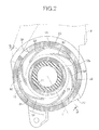
FIG. 2] FIG. 2 is an enlarged sectional view along line 2-2 inFIG. 1 . (first embodiment) - [
FIG. 3] FIG. 3 is a sectional view along line 3-3 inFIG. 2 . (first embodiment) - [
FIG. 4] FIG. 4 is an exploded perspective view of a support shaft and a spring receiving member. (first embodiment) -
- 5
- Side door
- 8
- Bracket
- 10
- Support seat
- 11
- Support shaft
- 12
- Bearing part
- 13
- Click mechanism
- 14
- Spring receiving member
- 15
- Spring receiving face
- 16
- Coil spring
- 23
- Spring housing part
- 31
- Lubricant reservoir
- 32
- First groove
- 33
- Second groove
- 34
- Drain hole
- V
- Vehicle
- A mode for carrying out the present invention is explained below by reference to the attached
FIG. 1 to FIG. 4 . - First, in
FIG. 1 , an upwardfacing support seat 10 and asupport shaft 11 rising from thesupport seat 10 are fixedly provided on aside door 5 side of a passenger vehicle V, aclick mechanism 13 for imparting a click feel to pivoting of abracket 8 supporting a mirror, which is not illustrated, is provided between opposing faces of thesupport seat 10 and a bearingpart 12 that is provided on thebracket 8 and pivotably supported on thesupport shaft 11, and acoil spring 16 is provided in a compressed state between aspring receiving member 14 fixed to thesupport shaft 11 and a flatspring receiving face 15 formed on a face of the bearingpart 12 on the side opposite to thesupport seat 10, thecoil spring 16 pressing thebearing part 12 toward thesupport seat 10 side. - A
base 6 is mounted on theside door 5, and asupport member 7 is mounted on thisbase 6 by means of a plurality ofscrew members 9. The upwardfacing support seat 10 and thesupport shaft 11 rising upward from thesupport seat 10 are provided on thissupport member 7, and thesupport member 7 having thesupport seat 10 and thesupport shaft 11 is fixedly provided on theside door 5 via thebase 6. - The
bracket 8 is covered by ahousing 17; thishousing 17 is formed from a housingmain portion 18 made of a synthetic resin, forming a window facing the mirror, and mounted on thebracket 8 by means of a plurality ofscrew members 20, and acover 19 made of a synthetic resin and engaged with and linked to the housingmain portion 18. Anelectric actuator 21 housed within thehousing 17 is secured to thebracket 8 by means of a plurality ofscrew members 22, and the mirror is driven so as to be tilted in the fore-and-aft and left-and right directions by means of theelectric actuator 21. - Referring in addition to
FIG. 2 andFIG. 3 , the bearingpart 12 provided on thebracket 8 integrally has atubular portion 12a surrounding thesupport shaft 11 and acollar portion 12b protruding radially outward from a base of thetubular portion 12a so as to oppose thesupport seat 10, and the flatspring receiving face 15 is formed on an upper face of thecollar portion 12b. Furthermore, a tubularspring housing part 23 is integrally provided with thebracket 8, thespring housing part 23 being connected to the outer peripheral edge of thespring receiving face 15 at right angles and extending upward, and thecoil spring 16 is housed within thespring housing part 23. - Referring in addition to
FIG. 4 , thecoil spring 16 is provided in a compressed state between thespring receiving face 15 and thespring receiving member 14 fixed to an extremity part of thesupport shaft 11. Thespring receiving member 14 is formed into a ring plate shape from metal while havingengagement projection portions support shaft 11 are a pair offitting grooves spring receiving member 14 move in the axial direction by fitting the pair ofengagement projection portions 14a thereinto and having an outer end part opening at the extremity of thesupport shaft 11, a pair ofguide grooves 26 having one end in the peripheral direction connected to the inner end of thefitting grooves 25 and guiding theengagement projection portions 14a from the inner end of thefitting grooves 25 toward the other side in the peripheral direction, and a pair ofengagement recess parts 27 recessed from the other end of theguide grooves 26 toward the extremity side of thesupport shaft 11 so as to make theengagement projection portions 14a engage therewith. After theengagement projection portions 14a of thespring receiving member 14 in a state in which thecoil spring 16 is present between itself and thespring receiving face 15 are fitted into the twofitting grooves 25, moved to their inner end parts, and then displaced in the peripheral direction toward theengagement recess parts 27 side, and thespring receiving member 14 is thereby engaged with thesupport shaft 11. The twoengagement projection portions 14a are engaged with the twoengagement recess parts 27 by means of the spring force exhibited by thecoil spring 16, and thespring receiving member 14 is thereby substantially fixed to thesupport shaft 11. - The
click mechanism 13 imparts a click feel when thebracket 8, that is, the mirror, pivots between a raised position in which it projects sideways from theside door 5, a forward retracted position in which it pivots from the raised position toward the front of the passenger vehicle V and is close to theside door 5, and a rearward retracted position in which it pivots from the raised position toward the rear of the passenger vehicle V and is close to theside door 5, and is provided between thesupport seat 10 and thecollar portion 12b of the bearingpart 12. - Referring in addition to
FIG. 4 , theclick mechanism 13 is formed from a plurality oftrapezoidal peaks 29 disposed at intervals on the periphery of thesupport shaft 11 and provided on thesupport seat 10 so as to formvalleys 28 therebetween, and threefitting projections 30 provided integrally with thecollar portion 12b of the bearingpart 12 while having a shape that can be fitted into each of thevalleys 28, and thecollar portion 12b is urged toward the side on which it moves closer to thesupport seat 10 by means of the spring force exhibited by thecoil spring 16. - In such a
click mechanism 13, in a state in which each of thefitting projections 30 is fitted into each of thevalleys 28, the raised position, the forward retracted position, or the rearward retracted position of thebracket 8 and the mirror is retained. Furthermore, since pivoting of thebracket 8 and the mirror from the raised position to the forward retracted position or the rearward retracted position becomes possible by each of thefitting projections 30 passing over each of thepeaks 29 against the spring force of thecoil spring 16, it is possible to impart a click feel to pivoting of thebracket 8 and the mirror between the raised position and the forward retracted position and pivoting of thebracket 8 and the mirror between the raised position and the rearward retracted position. - A
lubricant reservoir 31 that can be charged with a lubricant such as a grease is formed on thespring receiving face 15 restricted by thecollar portion 12b of the bearingpart 12; thislubricant reservoir 31 has at least afirst groove 32 that continues so that one end is disposed closer to the center of thesupport shaft 11 than the other end, and in this embodiment thefirst grooves 32 are disposed at a plurality of positions equally spaced in the peripheral direction of thespring receiving face 15. - Moreover, the
first grooves 32 are formed so as to diagonally intersect a virtual line L extending radially from the center of thesupport shaft 11 and passing through an intermediate part of thefirst groove 32, and in this embodiment they are formed into a curved shape that protrudes outward in the radial direction of thespring receiving face 15. - Furthermore, the
lubricant reservoir 31 is formed from a plurality of thefirst grooves 32 and an annularsecond groove 33 with which the other ends of thesefirst grooves 32 communicate in common, thesecond groove 33 being formed on an outer peripheral part of thespring receiving face 15 so as to be positioned further outward than the outer periphery of thecoil spring 16. - Due to the plurality of
first grooves 32 being formed on thespring receiving face 15, part of thecoil spring 16 does not abut against thespring receiving face 15 in a portion corresponding to thefirst grooves 32, but the line diameter of thecoil spring 16 and the groove width of thefirst grooves 32 are set so that thecoil spring 16 abuts directly against thespring receiving face 15 via at least 75% of the area of thecoil spring 16 when projected on thespring receiving face 15 in the axial direction of thesupport shaft 11. By so doing, it becomes possible to avoid a local increase of the load from thecoil spring 16 acting on thespring receiving face 15, prevent thecollar portion 12b from being deformed, prevent a step from being generated in a portion of thefirst grooves 32 due to deformation of thespring receiving face 15, and prevent the terminus of thecoil spring 16 from being caught by such a step. - Furthermore, a
drain hole 34 for discharging water entering the interior of thespring housing part 23 is provided in a location, closest to the ground, of thespring housing part 23 in a state in which thebracket 8 is supported on thesupport shaft 11. - The operation of this embodiment is now explained: since the
lubricant reservoir 31 formed on thespring receiving face 15 has at least thefirst groove 32, which continues so that one end is disposed closer to the center of thesupport shaft 11 than the other end, regardless of displacement of thecoil spring 16 caused by rattling between thebracket 8 and thecoil spring 16, lubricant can be always supplied to the area of thecoil spring 16 that is in sliding contact with thespring receiving face 15, friction between thespring receiving face 15 and thecoil spring 16 decreases, and the occurrence of an abnormal noise caused by rubbing of thespring receiving face 15 and thecoil spring 16 can be prevented. - Furthermore, since the
first groove 32 is formed so that it diagonally intersects the virtual line L passing through the intermediate part of thefirst groove 32 and extending radially from the center of thesupport shaft 11, if in the worst case the terminus of thecoil spring 16 is caught by thefirst groove 32, it is possible to prevent the generation of an abnormal noise when thecoil spring 16 returns by virtue of the spring reaction force. That is, when thefirst groove 32 is one that lies along the virtual line L extending radially from the center of thesupport shaft 11, if the terminus of thecoil spring 16 is caught by thefirst groove 32 during pivoting of thebracket 8, there is a possibility that an abnormal noise will be generated when thecoil spring 16 returns by virtue of the spring reaction force, but since thefirst groove 32 diagonally intersects the virtual line L extending radially from the center of thesupport shaft 11, even if the terminus of thecoil spring 16 is caught by thefirst groove 32, the resistance force is dispersed and it is easily released, and it is therefore possible to suppress twisting of thecoil spring 16 due to it being caught, reduce the spring reaction force, and prevent the occurrence of an abnormal noise when thecoil spring 16 returns. - Moreover, since the
first groove 32 has a curved shape, compared with a case in which thefirst groove 32 has a straight line shape the length of thefirst groove 32 is made longer, a larger amount of lubricant can be charged, and flowing out of the lubricant can be suppressed more effectively. - Furthermore, since the
lubricant reservoir 31 is formed from the plurality offirst grooves 32 disposed at a plurality of positions spaced in the peripheral direction of thespring receiving face 15 and the annularsecond groove 33 with which the other ends of thefirst grooves 32 are made to communicate in common, and thesecond groove 33 is formed on the outer peripheral part of thespring receiving face 15 so as to be positioned further outside than the outer periphery of thecoil spring 16, lubricant that attempts to escape toward the outer periphery of thespring receiving face 15 can be retained in thesecond groove 33 by means of thecoil spring 16 being in sliding contact with thespring receiving face 15, lubricant can be circulated evenly in the peripheral direction of thespring receiving face 15 by means of thesecond groove 33, and it is possible to reliably supply lubricant to the area of thecoil spring 16 that is in sliding contact with thespring receiving face 15. - Moreover, since the tubular
spring housing part 23 connected to the outer peripheral edge of thespring receiving face 15 at right angles and housing thecoil spring 16 is provided on thebracket 8, and thedrain hole 34 for discharging water within thespring housing part 23 is provided at a location, closest to the ground, of thespring housing part 23 in a state in which thebracket 8 is supported on thesupport shaft 11, the majority of the water that enters thespring housing part 23 and travels on the inner peripheral face of thespring housing part 23 can be discharged from thedrain hole 34 before reaching thespring receiving face 15, and it is possible to suppress lubricant from being discharged together with the water, thereby preventing as far as possible lubricant from flowing out from the area where thecoil spring 16 is in sliding contact. - A route for water to enter from the extremity of the
support shaft 11 and be discharged to thedrain hole 34 via an outer face of thesupport shaft 11, an outer face of the bearingpart 12 and thespring receiving face 15 could be considered, but since the amount of water in this part is relatively small and is an amount that would not make the lubricant be discharged together therewith, it is not necessary to pay particular consideration thereto. - An embodiment of the present invention is explained above, but the present invention is not limited to the above-mentioned embodiment and may be modified in a variety of ways as long as the modifications do not depart from the spirit and scope thereof.
Claims (5)
- A vehicle door mirror in which an upward facing support seat (10) and a support shaft (11) rising from the support seat (10) are fixedly provided on a side door (5) side of a vehicle (V), a click mechanism (13) is provided between opposing faces of the support seat (10) and a bearing part (12) provided on a bracket (8) supporting a mirror and pivotably supported on a base of the support shaft (11), the click mechanism (13) imparting a click feel to pivoting of the bracket (8), a coil spring (16) is provided in a compressed state between a spring receiving member (14) fixed to the support shaft (11) and a flat spring receiving face (15) formed on a face, on the opposite side to the support seat (10), of the bearing part (12), the coil spring (16) pressing the bearing part (12) toward the support seat (10) side, and a lubricant reservoir (31) that can be charged with a lubricant is formed on the spring receiving face (15), characterized in that the lubricant reservoir (31) has at least a first groove (32) that continues so that one end is disposed closer to the center of the support shaft (11) than the other end.
- The vehicle door mirror according to Claim 1, wherein the first groove (32) is formed so that a virtual line extending radially from the center of the support shaft (11) diagonally intersects an intermediate part of the first groove (32).
- The vehicle door mirror according to Claim 2, wherein the first groove (32) is formed into a curved shape.
- The vehicle door mirror according to any one of Claims 1 to 3, wherein the lubricant reservoir (31) is formed from a plurality of the first grooves (32) disposed at intervals in a peripheral direction of the spring receiving face (15), and an annular second groove (33) that said other ends of the first grooves (32) communicate with in common, and the second groove (33) is formed on an outer peripheral part of the spring receiving face (15) so as to be positioned further outside than an outer periphery of the coil spring (16).
- The vehicle door mirror according to any one of Claims 1 to 4, wherein a tubular spring housing part (23) is provided on the bracket (8), the spring housing part (23) being connected to an outer peripheral edge of the spring receiving face (15) at right angles and housing the coil spring (16), and a drain hole (34) for draining water within the spring housing part (23) is provided at a location, closest to the ground, of the spring housing part (23) in a state in which the bracket (8) is supported on the support shaft (11).
Applications Claiming Priority (2)
| Application Number | Priority Date | Filing Date | Title |
|---|---|---|---|
| JP2010158414A JP5426492B2 (en) | 2010-07-13 | 2010-07-13 | Vehicle door mirror |
| PCT/JP2011/059362 WO2012008193A1 (en) | 2010-07-13 | 2011-04-15 | Vehicle door mirror |
Publications (3)
| Publication Number | Publication Date |
|---|---|
| EP2594433A1 true EP2594433A1 (en) | 2013-05-22 |
| EP2594433A4 EP2594433A4 (en) | 2013-12-25 |
| EP2594433B1 EP2594433B1 (en) | 2014-11-19 |
Family
ID=45469206
Family Applications (1)
| Application Number | Title | Priority Date | Filing Date |
|---|---|---|---|
| EP11806525.9A Not-in-force EP2594433B1 (en) | 2010-07-13 | 2011-04-15 | Vehicle door mirror |
Country Status (6)
| Country | Link |
|---|---|
| US (1) | US8950878B2 (en) |
| EP (1) | EP2594433B1 (en) |
| JP (1) | JP5426492B2 (en) |
| CN (1) | CN102985292B (en) |
| BR (1) | BR112013000697B8 (en) |
| WO (1) | WO2012008193A1 (en) |
Cited By (6)
| Publication number | Priority date | Publication date | Assignee | Title |
|---|---|---|---|---|
| EP3103818A1 (en) | 2015-06-12 | 2016-12-14 | Borealis AG | Method and apparatus for polymerising olefins in gas phase |
| EP3184167A1 (en) | 2015-12-22 | 2017-06-28 | Borealis AG | A method for returning polymer to a fluidised bed reactor |
| EP3184166A1 (en) | 2015-12-22 | 2017-06-28 | Borealis AG | A method for withdrawing agglomerates from a fluidised bed reactor |
| EP3418309A1 (en) | 2017-06-20 | 2018-12-26 | Borealis AG | A method, an arrangement and use of an arrangement of preparing polymer |
| EP3418308A1 (en) | 2017-06-20 | 2018-12-26 | Borealis AG | A method, an arrangement and use of an arrangement for olefin polymerisation |
| WO2019238428A1 (en) | 2018-06-14 | 2019-12-19 | Borealis Ag | Process for polymerizing olefin in a gas phase reactor with improved thermal homogeneity |
Families Citing this family (3)
| Publication number | Priority date | Publication date | Assignee | Title |
|---|---|---|---|---|
| JP2015214219A (en) * | 2014-05-09 | 2015-12-03 | 株式会社石▲崎▼本店 | Vehicle side mirror |
| JP6463158B2 (en) * | 2015-02-05 | 2019-01-30 | 株式会社東海理化電機製作所 | Vehicle visual recognition device |
| JP7633661B2 (en) | 2021-05-31 | 2025-02-20 | 株式会社ペンストン | Vehicle viewing device with electrically operated storage unit |
Family Cites Families (13)
| Publication number | Priority date | Publication date | Assignee | Title |
|---|---|---|---|---|
| JPS6112847U (en) | 1984-06-28 | 1986-01-25 | 株式会社東海理化電機製作所 | foldable mirror |
| JPS62148444U (en) | 1986-03-13 | 1987-09-19 | ||
| JPH04136949U (en) | 1991-06-17 | 1992-12-21 | 株式会社村上開明堂 | foldable door mirror |
| JP2554990Y2 (en) * | 1991-10-29 | 1997-11-19 | 株式会社村上開明堂 | Folding door mirror |
| CN1115838A (en) | 1994-07-25 | 1996-01-31 | 李嘉贵 | Oil-removing drain valve |
| US6116743A (en) * | 1999-09-20 | 2000-09-12 | Donnelly Corporation | Extendable exterior rearview mirror assembly for vehicles |
| JP3954877B2 (en) | 2002-03-14 | 2007-08-08 | 株式会社ホンダロック | door mirror |
| JP2005199820A (en) | 2004-01-14 | 2005-07-28 | Ichikoh Ind Ltd | Mirror device for vehicle |
| JP2005254969A (en) * | 2004-03-11 | 2005-09-22 | Ichikoh Ind Ltd | Manually retractable vehicle outside mirror |
| CN2697377Y (en) | 2004-03-19 | 2005-05-04 | 万向钱潮股份有限公司 | Universal joint with special nylon washer in bearing |
| JP2006007925A (en) | 2004-06-24 | 2006-01-12 | Ichikoh Ind Ltd | Outside mirror for vehicle |
| JP4847311B2 (en) | 2006-12-25 | 2011-12-28 | 株式会社東海理化電機製作所 | Mirror device for vehicle |
| JP5082745B2 (en) * | 2007-10-11 | 2012-11-28 | 市光工業株式会社 | Outside mirror device for vehicle |
-
2010
- 2010-07-13 JP JP2010158414A patent/JP5426492B2/en active Active
-
2011
- 2011-04-15 WO PCT/JP2011/059362 patent/WO2012008193A1/en not_active Ceased
- 2011-04-15 US US13/807,976 patent/US8950878B2/en active Active
- 2011-04-15 BR BR112013000697A patent/BR112013000697B8/en active IP Right Grant
- 2011-04-15 CN CN201180034087.9A patent/CN102985292B/en active Active
- 2011-04-15 EP EP11806525.9A patent/EP2594433B1/en not_active Not-in-force
Cited By (13)
| Publication number | Priority date | Publication date | Assignee | Title |
|---|---|---|---|---|
| EP3103818A1 (en) | 2015-06-12 | 2016-12-14 | Borealis AG | Method and apparatus for polymerising olefins in gas phase |
| WO2016198631A1 (en) | 2015-06-12 | 2016-12-15 | Borealis Ag | Method and apparatus for polymerising olefins in gas phase |
| US11111324B2 (en) | 2015-12-22 | 2021-09-07 | Borealis Ag | Method for withdrawing agglomerates from a fluidized bed polymerization reactor |
| EP3184166A1 (en) | 2015-12-22 | 2017-06-28 | Borealis AG | A method for withdrawing agglomerates from a fluidised bed reactor |
| EP3184167A1 (en) | 2015-12-22 | 2017-06-28 | Borealis AG | A method for returning polymer to a fluidised bed reactor |
| EP3418309A1 (en) | 2017-06-20 | 2018-12-26 | Borealis AG | A method, an arrangement and use of an arrangement of preparing polymer |
| EP3418308A1 (en) | 2017-06-20 | 2018-12-26 | Borealis AG | A method, an arrangement and use of an arrangement for olefin polymerisation |
| WO2018234176A1 (en) | 2017-06-20 | 2018-12-27 | Borealis Ag | A method, an arrangement and use of an arrangement for olefin polymerisation |
| WO2018234175A1 (en) | 2017-06-20 | 2018-12-27 | Borealis Ag | A method, an arrangement and use of an arrangement of preparing polymer |
| US11208507B2 (en) | 2017-06-20 | 2021-12-28 | Borealis Ag | Method, an arrangement and use of an arrangement for olefin polymerisation |
| US11220558B2 (en) | 2017-06-20 | 2022-01-11 | Borealis Ag | Method, an arrangement and use of an arrangement of preparing polymer |
| WO2019238428A1 (en) | 2018-06-14 | 2019-12-19 | Borealis Ag | Process for polymerizing olefin in a gas phase reactor with improved thermal homogeneity |
| US12018102B2 (en) | 2018-06-14 | 2024-06-25 | Borealis Ag | Process for polymerizing olefin in a gas phase reactor with improved thermal homogeneity |
Also Published As
| Publication number | Publication date |
|---|---|
| BR112013000697A2 (en) | 2016-05-17 |
| CN102985292A (en) | 2013-03-20 |
| EP2594433A4 (en) | 2013-12-25 |
| WO2012008193A1 (en) | 2012-01-19 |
| US8950878B2 (en) | 2015-02-10 |
| JP2012020609A (en) | 2012-02-02 |
| EP2594433B1 (en) | 2014-11-19 |
| CN102985292B (en) | 2015-06-24 |
| US20130194685A1 (en) | 2013-08-01 |
| BR112013000697B8 (en) | 2022-07-19 |
| JP5426492B2 (en) | 2014-02-26 |
| BR112013000697B1 (en) | 2020-02-18 |
Similar Documents
| Publication | Publication Date | Title |
|---|---|---|
| EP2594433B1 (en) | Vehicle door mirror | |
| CN107867204B (en) | Seat slide device for vehicle | |
| US8242366B2 (en) | Power supplying system for a sliding structure | |
| US12330539B2 (en) | Seat-rotating device | |
| US20100284733A1 (en) | Axial Ball Joint with Impact Damping Mechanism | |
| WO2014061599A1 (en) | Pulley device | |
| JPH09104322A (en) | Deflector mounting component for safety belt | |
| JP2019009998A (en) | motor | |
| CN109416078A (en) | Sliding bearing | |
| US6912811B2 (en) | Window regulator | |
| US10730438B2 (en) | Vehicle door mirror including vibration suppressing support | |
| CN106994955B (en) | Buckle device | |
| JP5930665B2 (en) | Vehicle window regulator device | |
| JP5392547B2 (en) | Opening and closing body support structure | |
| US20230391263A1 (en) | Step apparatus for vehicle | |
| JP7789552B2 (en) | Wiring structure for sliding doors | |
| KR102950847B1 (en) | Motor apparatus with improved thrust support structure of bearing | |
| CN219413277U (en) | Injection molding plane spherical bearing retainer | |
| JP4161882B2 (en) | Sliding door device | |
| CN113726063B (en) | Motor unit for skylight | |
| JP7573504B2 (en) | Connection mechanism and door drive device | |
| KR20220040031A (en) | Hinge device of console armrest for car | |
| JP2014238155A (en) | Cover member | |
| JP7495894B2 (en) | Baffle plate | |
| CN214799190U (en) | Friction spring assembly and sliding plate type motor with same |
Legal Events
| Date | Code | Title | Description |
|---|---|---|---|
| PUAI | Public reference made under article 153(3) epc to a published international application that has entered the european phase |
Free format text: ORIGINAL CODE: 0009012 |
|
| 17P | Request for examination filed |
Effective date: 20130108 |
|
| AK | Designated contracting states |
Kind code of ref document: A1 Designated state(s): AL AT BE BG CH CY CZ DE DK EE ES FI FR GB GR HR HU IE IS IT LI LT LU LV MC MK MT NL NO PL PT RO RS SE SI SK SM TR |
|
| DAX | Request for extension of the european patent (deleted) | ||
| REG | Reference to a national code |
Ref country code: DE Ref legal event code: R079 Ref document number: 602011011637 Country of ref document: DE Free format text: PREVIOUS MAIN CLASS: B60R0001076000 Ipc: B60R0001074000 |
|
| A4 | Supplementary search report drawn up and despatched |
Effective date: 20131125 |
|
| RIC1 | Information provided on ipc code assigned before grant |
Ipc: F16C 11/04 20060101ALI20131119BHEP Ipc: F16C 17/00 20060101ALI20131119BHEP Ipc: B60R 1/074 20060101AFI20131119BHEP Ipc: B60R 1/06 20060101ALI20131119BHEP |
|
| GRAP | Despatch of communication of intention to grant a patent |
Free format text: ORIGINAL CODE: EPIDOSNIGR1 |
|
| INTG | Intention to grant announced |
Effective date: 20140624 |
|
| GRAS | Grant fee paid |
Free format text: ORIGINAL CODE: EPIDOSNIGR3 |
|
| GRAA | (expected) grant |
Free format text: ORIGINAL CODE: 0009210 |
|
| AK | Designated contracting states |
Kind code of ref document: B1 Designated state(s): AL AT BE BG CH CY CZ DE DK EE ES FI FR GB GR HR HU IE IS IT LI LT LU LV MC MK MT NL NO PL PT RO RS SE SI SK SM TR |
|
| REG | Reference to a national code |
Ref country code: GB Ref legal event code: FG4D |
|
| REG | Reference to a national code |
Ref country code: CH Ref legal event code: EP |
|
| REG | Reference to a national code |
Ref country code: AT Ref legal event code: REF Ref document number: 696795 Country of ref document: AT Kind code of ref document: T Effective date: 20141215 |
|
| REG | Reference to a national code |
Ref country code: IE Ref legal event code: FG4D |
|
| REG | Reference to a national code |
Ref country code: DE Ref legal event code: R096 Ref document number: 602011011637 Country of ref document: DE Effective date: 20141231 |
|
| REG | Reference to a national code |
Ref country code: NL Ref legal event code: VDEP Effective date: 20141119 |
|
| REG | Reference to a national code |
Ref country code: AT Ref legal event code: MK05 Ref document number: 696795 Country of ref document: AT Kind code of ref document: T Effective date: 20141119 |
|
| REG | Reference to a national code |
Ref country code: LT Ref legal event code: MG4D |
|
| PG25 | Lapsed in a contracting state [announced via postgrant information from national office to epo] |
Ref country code: LT Free format text: LAPSE BECAUSE OF FAILURE TO SUBMIT A TRANSLATION OF THE DESCRIPTION OR TO PAY THE FEE WITHIN THE PRESCRIBED TIME-LIMIT Effective date: 20141119 Ref country code: PT Free format text: LAPSE BECAUSE OF FAILURE TO SUBMIT A TRANSLATION OF THE DESCRIPTION OR TO PAY THE FEE WITHIN THE PRESCRIBED TIME-LIMIT Effective date: 20150319 Ref country code: NO Free format text: LAPSE BECAUSE OF FAILURE TO SUBMIT A TRANSLATION OF THE DESCRIPTION OR TO PAY THE FEE WITHIN THE PRESCRIBED TIME-LIMIT Effective date: 20150219 Ref country code: ES Free format text: LAPSE BECAUSE OF FAILURE TO SUBMIT A TRANSLATION OF THE DESCRIPTION OR TO PAY THE FEE WITHIN THE PRESCRIBED TIME-LIMIT Effective date: 20141119 Ref country code: FI Free format text: LAPSE BECAUSE OF FAILURE TO SUBMIT A TRANSLATION OF THE DESCRIPTION OR TO PAY THE FEE WITHIN THE PRESCRIBED TIME-LIMIT Effective date: 20141119 Ref country code: IS Free format text: LAPSE BECAUSE OF FAILURE TO SUBMIT A TRANSLATION OF THE DESCRIPTION OR TO PAY THE FEE WITHIN THE PRESCRIBED TIME-LIMIT Effective date: 20150319 Ref country code: NL Free format text: LAPSE BECAUSE OF FAILURE TO SUBMIT A TRANSLATION OF THE DESCRIPTION OR TO PAY THE FEE WITHIN THE PRESCRIBED TIME-LIMIT Effective date: 20141119 |
|
| PG25 | Lapsed in a contracting state [announced via postgrant information from national office to epo] |
Ref country code: LV Free format text: LAPSE BECAUSE OF FAILURE TO SUBMIT A TRANSLATION OF THE DESCRIPTION OR TO PAY THE FEE WITHIN THE PRESCRIBED TIME-LIMIT Effective date: 20141119 Ref country code: RS Free format text: LAPSE BECAUSE OF FAILURE TO SUBMIT A TRANSLATION OF THE DESCRIPTION OR TO PAY THE FEE WITHIN THE PRESCRIBED TIME-LIMIT Effective date: 20141119 Ref country code: GR Free format text: LAPSE BECAUSE OF FAILURE TO SUBMIT A TRANSLATION OF THE DESCRIPTION OR TO PAY THE FEE WITHIN THE PRESCRIBED TIME-LIMIT Effective date: 20150220 Ref country code: PL Free format text: LAPSE BECAUSE OF FAILURE TO SUBMIT A TRANSLATION OF THE DESCRIPTION OR TO PAY THE FEE WITHIN THE PRESCRIBED TIME-LIMIT Effective date: 20141119 Ref country code: AT Free format text: LAPSE BECAUSE OF FAILURE TO SUBMIT A TRANSLATION OF THE DESCRIPTION OR TO PAY THE FEE WITHIN THE PRESCRIBED TIME-LIMIT Effective date: 20141119 Ref country code: HR Free format text: LAPSE BECAUSE OF FAILURE TO SUBMIT A TRANSLATION OF THE DESCRIPTION OR TO PAY THE FEE WITHIN THE PRESCRIBED TIME-LIMIT Effective date: 20141119 Ref country code: CY Free format text: LAPSE BECAUSE OF FAILURE TO SUBMIT A TRANSLATION OF THE DESCRIPTION OR TO PAY THE FEE WITHIN THE PRESCRIBED TIME-LIMIT Effective date: 20141119 Ref country code: SE Free format text: LAPSE BECAUSE OF FAILURE TO SUBMIT A TRANSLATION OF THE DESCRIPTION OR TO PAY THE FEE WITHIN THE PRESCRIBED TIME-LIMIT Effective date: 20141119 |
|
| PG25 | Lapsed in a contracting state [announced via postgrant information from national office to epo] |
Ref country code: SK Free format text: LAPSE BECAUSE OF FAILURE TO SUBMIT A TRANSLATION OF THE DESCRIPTION OR TO PAY THE FEE WITHIN THE PRESCRIBED TIME-LIMIT Effective date: 20141119 Ref country code: DK Free format text: LAPSE BECAUSE OF FAILURE TO SUBMIT A TRANSLATION OF THE DESCRIPTION OR TO PAY THE FEE WITHIN THE PRESCRIBED TIME-LIMIT Effective date: 20141119 Ref country code: CZ Free format text: LAPSE BECAUSE OF FAILURE TO SUBMIT A TRANSLATION OF THE DESCRIPTION OR TO PAY THE FEE WITHIN THE PRESCRIBED TIME-LIMIT Effective date: 20141119 Ref country code: EE Free format text: LAPSE BECAUSE OF FAILURE TO SUBMIT A TRANSLATION OF THE DESCRIPTION OR TO PAY THE FEE WITHIN THE PRESCRIBED TIME-LIMIT Effective date: 20141119 Ref country code: RO Free format text: LAPSE BECAUSE OF FAILURE TO SUBMIT A TRANSLATION OF THE DESCRIPTION OR TO PAY THE FEE WITHIN THE PRESCRIBED TIME-LIMIT Effective date: 20141119 |
|
| REG | Reference to a national code |
Ref country code: DE Ref legal event code: R097 Ref document number: 602011011637 Country of ref document: DE |
|
| PLBE | No opposition filed within time limit |
Free format text: ORIGINAL CODE: 0009261 |
|
| STAA | Information on the status of an ep patent application or granted ep patent |
Free format text: STATUS: NO OPPOSITION FILED WITHIN TIME LIMIT |
|
| 26N | No opposition filed |
Effective date: 20150820 |
|
| PG25 | Lapsed in a contracting state [announced via postgrant information from national office to epo] |
Ref country code: LU Free format text: LAPSE BECAUSE OF FAILURE TO SUBMIT A TRANSLATION OF THE DESCRIPTION OR TO PAY THE FEE WITHIN THE PRESCRIBED TIME-LIMIT Effective date: 20150415 Ref country code: MC Free format text: LAPSE BECAUSE OF FAILURE TO SUBMIT A TRANSLATION OF THE DESCRIPTION OR TO PAY THE FEE WITHIN THE PRESCRIBED TIME-LIMIT Effective date: 20141119 |
|
| REG | Reference to a national code |
Ref country code: CH Ref legal event code: PL |
|
| PG25 | Lapsed in a contracting state [announced via postgrant information from national office to epo] |
Ref country code: IT Free format text: LAPSE BECAUSE OF FAILURE TO SUBMIT A TRANSLATION OF THE DESCRIPTION OR TO PAY THE FEE WITHIN THE PRESCRIBED TIME-LIMIT Effective date: 20141119 |
|
| REG | Reference to a national code |
Ref country code: IE Ref legal event code: MM4A |
|
| PG25 | Lapsed in a contracting state [announced via postgrant information from national office to epo] |
Ref country code: CH Free format text: LAPSE BECAUSE OF NON-PAYMENT OF DUE FEES Effective date: 20150430 Ref country code: LI Free format text: LAPSE BECAUSE OF NON-PAYMENT OF DUE FEES Effective date: 20150430 |
|
| PG25 | Lapsed in a contracting state [announced via postgrant information from national office to epo] |
Ref country code: SI Free format text: LAPSE BECAUSE OF FAILURE TO SUBMIT A TRANSLATION OF THE DESCRIPTION OR TO PAY THE FEE WITHIN THE PRESCRIBED TIME-LIMIT Effective date: 20141119 |
|
| REG | Reference to a national code |
Ref country code: FR Ref legal event code: PLFP Year of fee payment: 6 |
|
| PG25 | Lapsed in a contracting state [announced via postgrant information from national office to epo] |
Ref country code: IE Free format text: LAPSE BECAUSE OF NON-PAYMENT OF DUE FEES Effective date: 20150415 |
|
| PG25 | Lapsed in a contracting state [announced via postgrant information from national office to epo] |
Ref country code: MT Free format text: LAPSE BECAUSE OF FAILURE TO SUBMIT A TRANSLATION OF THE DESCRIPTION OR TO PAY THE FEE WITHIN THE PRESCRIBED TIME-LIMIT Effective date: 20141119 |
|
| REG | Reference to a national code |
Ref country code: FR Ref legal event code: PLFP Year of fee payment: 7 |
|
| PGFP | Annual fee paid to national office [announced via postgrant information from national office to epo] |
Ref country code: FR Payment date: 20170313 Year of fee payment: 7 |
|
| PG25 | Lapsed in a contracting state [announced via postgrant information from national office to epo] |
Ref country code: SM Free format text: LAPSE BECAUSE OF FAILURE TO SUBMIT A TRANSLATION OF THE DESCRIPTION OR TO PAY THE FEE WITHIN THE PRESCRIBED TIME-LIMIT Effective date: 20141119 Ref country code: BG Free format text: LAPSE BECAUSE OF FAILURE TO SUBMIT A TRANSLATION OF THE DESCRIPTION OR TO PAY THE FEE WITHIN THE PRESCRIBED TIME-LIMIT Effective date: 20141119 Ref country code: HU Free format text: LAPSE BECAUSE OF FAILURE TO SUBMIT A TRANSLATION OF THE DESCRIPTION OR TO PAY THE FEE WITHIN THE PRESCRIBED TIME-LIMIT; INVALID AB INITIO Effective date: 20110415 |
|
| PGFP | Annual fee paid to national office [announced via postgrant information from national office to epo] |
Ref country code: GB Payment date: 20170412 Year of fee payment: 7 |
|
| PG25 | Lapsed in a contracting state [announced via postgrant information from national office to epo] |
Ref country code: TR Free format text: LAPSE BECAUSE OF FAILURE TO SUBMIT A TRANSLATION OF THE DESCRIPTION OR TO PAY THE FEE WITHIN THE PRESCRIBED TIME-LIMIT Effective date: 20141119 |
|
| PG25 | Lapsed in a contracting state [announced via postgrant information from national office to epo] |
Ref country code: BE Free format text: LAPSE BECAUSE OF FAILURE TO SUBMIT A TRANSLATION OF THE DESCRIPTION OR TO PAY THE FEE WITHIN THE PRESCRIBED TIME-LIMIT Effective date: 20141119 |
|
| PG25 | Lapsed in a contracting state [announced via postgrant information from national office to epo] |
Ref country code: MK Free format text: LAPSE BECAUSE OF FAILURE TO SUBMIT A TRANSLATION OF THE DESCRIPTION OR TO PAY THE FEE WITHIN THE PRESCRIBED TIME-LIMIT Effective date: 20141119 |
|
| PG25 | Lapsed in a contracting state [announced via postgrant information from national office to epo] |
Ref country code: AL Free format text: LAPSE BECAUSE OF FAILURE TO SUBMIT A TRANSLATION OF THE DESCRIPTION OR TO PAY THE FEE WITHIN THE PRESCRIBED TIME-LIMIT Effective date: 20141119 |
|
| GBPC | Gb: european patent ceased through non-payment of renewal fee |
Effective date: 20180415 |
|
| PG25 | Lapsed in a contracting state [announced via postgrant information from national office to epo] |
Ref country code: GB Free format text: LAPSE BECAUSE OF NON-PAYMENT OF DUE FEES Effective date: 20180415 |
|
| PG25 | Lapsed in a contracting state [announced via postgrant information from national office to epo] |
Ref country code: FR Free format text: LAPSE BECAUSE OF NON-PAYMENT OF DUE FEES Effective date: 20180430 |
|
| PGFP | Annual fee paid to national office [announced via postgrant information from national office to epo] |
Ref country code: DE Payment date: 20220302 Year of fee payment: 12 |
|
| REG | Reference to a national code |
Ref country code: DE Ref legal event code: R119 Ref document number: 602011011637 Country of ref document: DE |
|
| PG25 | Lapsed in a contracting state [announced via postgrant information from national office to epo] |
Ref country code: DE Free format text: LAPSE BECAUSE OF NON-PAYMENT OF DUE FEES Effective date: 20231103 |