EP2594430B1 - Blade transport wagon - Google Patents
Blade transport wagon Download PDFInfo
- Publication number
- EP2594430B1 EP2594430B1 EP12193202.4A EP12193202A EP2594430B1 EP 2594430 B1 EP2594430 B1 EP 2594430B1 EP 12193202 A EP12193202 A EP 12193202A EP 2594430 B1 EP2594430 B1 EP 2594430B1
- Authority
- EP
- European Patent Office
- Prior art keywords
- transport dolly
- blade transport
- blade
- dolly
- coupling
- Prior art date
- Legal status (The legal status is an assumption and is not a legal conclusion. Google has not performed a legal analysis and makes no representation as to the accuracy of the status listed.)
- Not-in-force
Links
Images


Classifications
-
- B—PERFORMING OPERATIONS; TRANSPORTING
- B60—VEHICLES IN GENERAL
- B60P—VEHICLES ADAPTED FOR LOAD TRANSPORTATION OR TO TRANSPORT, TO CARRY, OR TO COMPRISE SPECIAL LOADS OR OBJECTS
- B60P3/00—Vehicles adapted to transport, to carry or to comprise special loads or objects
- B60P3/40—Vehicles adapted to transport, to carry or to comprise special loads or objects for carrying long loads, e.g. with separate wheeled load supporting elements
Description
- The present invention concerns a blade transport dolly for towing a blade for a wind energy plant, wherein the blade transport dolly at least includes a chassis with a front end and a rear end, wherein at or in the immediate vicinity of the front end of the blade transport dolly there is arranged a coupling device for coupling the blade transport dolly to a towing vehicle, where the blade transport dolly further includes a rear end for coupling to the blade to be towed, and a number of wheel axles with wheels arranged at the front end, at the rear end, or between the ends, respectively, that the blade transport dolly at its rear end includes at least one rearwardly directed coupling means adapted with securing means for lockable coupling to a corresponding coupling part on a lift beam or a blade of the type which the blade transport dolly is adapted to tow.
- It is commonly known that i.a. blades, towers and nacelles for modem wind energy plants are to be transported in connection with production, shipping and other handling. This transport is frequently difficult as they are heavy and not the least elongated objects, in particular when speaking of blades that easily are up to about 60 m long and which in the future will have lengths up to 80 m and even more. With regard to blades, the weight of a blade of 50-60 m is about 16-19 metric tons while the diameter at the root end of a blade is between 250 and 350 cm, and even larger. With regard to tower elements, the diameter is greater and the weight even higher, and the heaviest are the assembled nacelles that easily can weigh 150 metric tons or more. For example, the nacelle for a 6 MW wind energy plant weighs 235 metric tons.
- Moving and transporting tower elements and nacelles is thus markedly different from moving blades due to the appreciably lower weight of wings but also due to the fact that blades for wind energy plants are much more flexible/elastic and fragile, why the way of supporting and handling blades is somewhat different from the way of handling towers and nacelles.
- Blades for wind energy plants are typically made of fibre-reinforced plastic, also called composite. At the root end of the blade where typically a steel flange is integrated, there is commonly fitted a kind of transport rack or frame. This frame usually includes a pair of legs for bearing on the base such that the blade is supported and kept at a distance from the base by this frame. Similarly, there is usually provided a support about 2/3 of the length of the blade from the root end and towards the tip end. This support typically also has a pair of legs. By moving a blade with such frames there is typically used a crane or a large forklift truck for moving the blade, which is necessary typically when moving it between various steps during production, to a storage area, to a harbour for shipping or the like.
- Moving a blade as described above is typically effected by arranging lift straps around the blade after which it is lifted off the base and moved. However, this is not a very expedient way of proceeding as it requires a large forklift truck with a very special lifting yoke, and at the same time such a moving requires much space in width as well as length since the blade is moved while disposed more or less transversely to the forklift truck. The crane or the forklift truck are furthermore rather large as lifting and moving of such large object not only require the ability to lift a great weight but also the presence of a heavy counterweight on e.g. a forklift truck. The great counterweight is necessary in order to perform a secure lifting which typically occurs at a relatively large distance from the front wheels on the forklift truck. In order to prevent the forklift truck from tipping over, it is provided with a heavy rear end to ensure a secure moving operation.
- In connection with moving across longer distances, sometimes low trucks are used on which the blade is placed by crane or forklift truck. This solution, however, requires lifting on as well as off which all things considered is associated with expenses and much time consumption.
- There are solutions too wherein there is arranged a dolly under the tip end of the blade and wherein a steel frame is mounted on the blade root, where cutouts are arranged in the steel frame in the form of holes for the forks of a forklift. The root end of the blade can be lifted off the base by a forklift truck and moved as the blade and thereby the dolly under the blade tip are towed. However, this solution has the drawback that it can be difficult to prevent a twist occurring in the blade during the moving, which is completely undesirable.
- However, a partial solution to the challenge of preventing the occurrence of a twist in the blade is indicated as fittings bolted on the blade to be moved are used. This fitting is connected via a king pin to a transverse beam which typically is resting on the base. In this transverse beam there are cutouts for forks of forklift trucks such as to lift and subsequently tow the blade to the desired place. Hereby is achieved a movable link between the blade and the forklift truck, providing a greater manoeuvrability. However, a rather large forklift truck with an unloaden weight of up to 50 metric tons or more is still required, which cannot always be expected to be accessible for economic reasons at the areas where movements commonly occur.
- From
DE 20 2010 015 762 U1 the preamble ofclaim 1 is known and it shows a solution for transporting tower segments for wind turbines is known. The solution comprises a kind of dolly that via coupling means can be attached to a tower section at the end flange, preferably at both ends of a tower section, where - due to the stiffness of the tower section - a transport can take place. The dolly comprises a number of axles comprising wheels and has an certain extension away from the coupling means in order to have said axles and wheels arranged. - It is the object of the invention to indicate a solution where large and long blades for wind energy plants can be moved in a simple and uncomplicated way, wherein the moving is effected by using an implement according to the invention and otherwise by applying commonly occurring transport equipment.
- The present invention concerns a blade transport dolly for towing a blade for a wind energy plant, wherein the blade transport dolly at least includes a chassis with a front end and a rear end, wherein at or in the immediate vicinity of the front end of the blade transport dolly there is arranged a coupling device for coupling the blade transport dolly to a towing vehicle.
- The blade transport dolly further includes a rear end for coupling to the blade to be towed, and a number of wheel axles with wheels arranged at the front end, at the rear end, or between the ends, respectively, that the blade transport dolly at its rear end includes at least one rearwardly directed coupling means adapted with securing means for lockable coupling to a corresponding coupling part on a lift beam or a blade of the type which the blade transport dolly is adapted to tow.
- The new features of a blade transport dolly according to the invention are that the blade transport dolly, at the front end of the blade transport dolly chassis, comprises a counterweight, said counterweight comprising a ballast, e.g. a container filled with concrete or other suitable ballast or where said ballast is constituted by steel items, concrete items or other means with sufficient weight.
- A blade transport dolly according to the invention is thus adapted with means for being towed by a vehicle. A suitable vehicle which is usually at hand where goods are handled and moved may e.g. be a so-called terminal tractor which is typically used for moving semitrailers. By a blade transport dolly according to the invention and a terminal tractor is achieved a simple solution by which blades for wind energy plants can immediately be moved in a factory area, in a storage area and/or in a harbour area. The terminal tractor does not require any special conditions and is a simple tool which is operated without great cost. By coupling a blade transport dolly to a terminal tractor moving the actual objects can readily be performed. By coupling the front end of a blade transport dolly to a terminal tractor, or for that matter to a lorry, the blade transport dolly itself can be moved to couple with the object at the rear end of the blade transport dolly.
- The moving occurs by the rearwardly directed coupling means being brought to engage corresponding coupling means on the object, after which the blade transport dolly so to say forms an intermediate link between the object and the terminal tractor. As the blade transport dolly is equipped with at least two wheels at each their side, it can immediately be moved into position relative to the object or to coupling members adapted for the purpose thereon.
- In a particularly preferred variant of a blade transport dolly according to the invention it further includes a steering part, the steering part including the wheel axles with wheels, and where between the chassis and steering part there is arranged at least one passive steering rod.
- By mounting the steering part on the chassis of the blade transport dolly at a vertical rotary axis and by connecting a steering rod from the chassis to each wheel on the steering part, there is achieved the effect that the blade transport dolly will turn as well when the towing vehicle is turning. Hereby is ensured that no twist is applied via transport dolly, coupling means or other members to the moved object. This is particularly significant for blades for wind energy plants as they can be deformed and damaged by too large load thereon.
- In yet a variant of a blade transport dolly according to the invention one or more active steering rods can be mounted. This may e.g. be a hydraulic cylinder where actuation causes that a more directly controlled steering of the blade transport dolly can be performed.
- A blade transport dolly according to the invention may be designed such that it is the rear end of the blade transport dolly which constitutes a steering part. This steering part can be pivotably fixed to the chassis by a substantially vertical axis, and be arranged at each of the transverse ends with a wheel which is pivotable about a substantially vertical axis as well. Hereby is achieved a compact and robust design which is easy to manoeuvre.
- In a preferred variant of a blade transport dolly according to the invention the rearwardly directed coupling means can be equipped with means such that the coupling means is/are displaceable in vertical direction between a lower position and an upper position, the difference between the lower and upper positions being between 5 cm and 100 cm, preferably about 50 cm. Hereby it is possible to lift the object off the base prior to moving or transport.
- A blade transport dolly according to the invention may advantageously be designed such that the rearwardly directed coupling means includes a lift tower including one or more linear actuators, including one or more one or more hydraulic cylinders. By the term lift tower is meant a lifting system wherein the coupling means can be displaced up and down in a kind of rail as it is known from a so-called truck tower on a forklift truck. Here it is just a rather modest lifting height as the purpose is only to lift the object off the base and to ensure a given ground clearance during the moving of the object. The mentioned lifting and lowering of the rearwardly directed coupling means can readily be performed with other kinds of mechanisms, and the method itself by which the desired movement is achieved is not so essential.
- In a practical variant according to the invention, a blade transport dolly can be made with rearwardly directed coupling means which include two parallel lift forks wherein the two lift forks are arranged with mutual spacing and with a length corresponding to a coupling part on an object of the type which the blade transport dolly is suited to tow, and wherein at least one of the lift forks includes securing means for securing the engagement with a corresponding coupling part. The spacing between the lift forks can e.g. be 100 cm, but may be greater or lesser as well. However, it is rather obvious that a standard spacing should correspond to the coupling means arranged in connection with the object. At the same time it is important that the coupling means are equipped with securing means which e.g. can be a bolt which after coupling can be passed through an aperture in one or both lift forks whereby the latter cannot immediately be pulled out for the corresponding coupling means on the object.
- The mentioned corresponding coupling means on the object may advantageously be constituted by a steel frame bolted on a blade root and which via a king pin is rotatably connected with a lift beam in which is arranged cutouts or apertures for the lift forks. This lift fork can e.g. be 30 cm thick why the lift forks e.g. can be 40 cm long so that they extend through the lift beam and so that a safety bolt can be fitted in the lift fork at the other side of the lift beam.
- A blade transport dolly according to the invention may advantageously be designed such that the rearwardly directed coupling means are laterally displaced relative to a central longitudinal axis extending from the rear end to the front end of the blade transport dolly. Hereby it is possible to compensate for the displaced centre of gravity of an object. For example, a blade for a wind energy plant has a centre of gravity which is offset relative to the longitudinal centre line of the root end. Such an uneven distribution of weight can be compensated for by arranging the entire rearwardly coupling part offset relative to the centre line of the blade transport dolly.
- In a variant of a blade transport dolly according to the invention the rearwardly coupling means can be mechanically displaceable in the transverse direction of the blade transport dolly. Hereby is achieved the possibility of adapting the blade transport dolly to different types of blades or other objects whether the centre of gravity is offset or not.
- A possible way of handling objects with offset or not offset centres of gravity is to set the position of the rearwardly directed coupling means according to data for the object in question. Another possibility is that a blade transport dolly according to the invention includes at least two weigh cells either arranged between the rearwardly directed coupling means and the blade transport dolly itself or arranged in connection with the wheel axles of the blade transport dolly, for determining the load applied on each of the axles of the blade transport dolly. By using input from such weigh cells, the position of the rearwardly directed coupling means can be adjusted rather precisely with regard to the actual object to be moved. Such an adjustment can be performed manually or automatically with means suited for the purpose.
- In an absolutely preferred embodiment of a blade transport dolly according to the invention there is arranged a king pin at the front end on the chassis of the blade transport dolly for coupling to a standardised semitrailer stool on a vehicle. The vehicle can be any kind of vehicle, including the previously mentioned terminal tractor or a lorry with suitable coupling means. By a king pin and a stool are achieved a good and secure solution which is well-known and which is readily applied.
- Finally, a blade transport dolly can be provided with one or more support legs as known from semitrailers and from standalone platforms such that it can be parked in periods where it is not in use.
- The invention is described in the following with reference to the drawing, wherein:
- Fig. 1
- shows a blade transport dolly as seen from above and obliquely from behind;
- Fig. 2
- shows a blade transport dolly as seen from the side and with a lift beam on the rearwardly directed coupling means;
- Fig. 3
- shows a blade transport dolly as seen from below and from the side;
- Fig. 4
- shows a blade transport dolly as seen from the side and with a blade;
- Fig. 5
- shows a tipping dolly under a blade.
- In the explanation of the Figures, identical or corresponding elements will be provided with the same designations in different Figures. Therefore, no explanation of all details will be given in connection with each single Figure/embodiment.
-
- 1
- blade transport dolly
- 2
- chassis
- 3
- front end
- 4
- rear end
- 5
- counterweight
- 6
- support legs
- 7
- rearwardly directed coupling means
- 8
- lift fork
- 9
- securing means on lift forks
- 10
- lift tower
- 11
- steering part
- 12
- rotary axis for steering part
- 13
- wheels
- 14
- wheel axle
- 15
- wheel suspension
- 16
- steering rod
- 17
- vertical rotary axes for wheel suspensions
- 18
- lift beam
- 19
- corresponding coupling means in lift beam
- 20
- king pin on chassis
- 21
- object/blade for wind energy plant
- 22
- tipping dolly
-
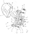
Fig. 1 shows ablade transport dolly 1 as seen from above and obliquely from behind; Theblade transport dolly 1 consists of a central andlongitudinal chassis 2 with afront end 3 and arear end 4. At thefront end 3 is disposed acounterweight 5, here in the shape of a closed container in which ballast can be filled, e.g. concrete. Under the counterweight along the side is seen asupport leg 6 in folded up condition. Thesupport leg 6 can be released from the shown position and pivoted to vertical position and may thus support theblade transport dolly 1 at thefront end 3. - At the
rear end 4 of theblade transport dolly 1 the rearwardly directed coupling means 7 are seen, here including two lift forks 8 provided with securing means 9 at the ends. The securing means 9 in the shown variant are constituted by vertical through-going holes in the lift forks 8 for receiving a not shown safety bolt, and a thickening at the ends of the lift forks. The lift forks 8 are arranged on alift tower 10 by which the lift forks can be moved between a lower position and an upper position. The lifting height is about 50 cm in the shown variant. Thelift tower 10 and thereby also the lift forks 8 are here seen displaced towards the left side of the blade transport dolly whereby there is compensated for an offset centre of gravity on the object to be moved. - The
rear end 4 is here made as asteering part 11 which is connected to thechassis 2 by a vertical axis ofrotation 12. At the ends of the steering part in transverse direction appearwheels 13 which viawheel axles 14 are connected towheel suspensions 15. Betweenwheel suspension 15 andchassis 2 are seen two steeringrods 16, one at each side of thechassis 2. Thewheel suspensions 15 are fixed to thesteering part 11 at the vertical rotary axes 17, and when the chassis is forced to one of the sides the result is that the steeringrods 16 act on thewheel suspensions 15, whereby therear end 4 of theblade transport dolly 1 is easily and elegantly steered without causing twist in the moved object. - In
Fig. 2 appears ablade transport dolly 1 as also shown inFig. 1 , but here seen from the side and with alift beam 18 on the rearwardly directed lift forks 8. It appears on the Figure that the securing means 9 on the lift forks 8 protrude a bit on the other side of the corresponding coupling means 19 in thelift beam 18 whereby securing is enabled. Thelift beam 18 is here shown in a simplified embodiment as it will be provided with fittings for direct or indirect joining with the object to be moved. -
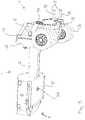
Fig. 3 shows ablade transport dolly 1 as seen from below and from the side where particularly theking pin 20 on thechassis 2 appears. Theking pin 20 is here made such that it fits with a standardised semitrailer stool on a vehicle. It is thus possible to use theblade transport dolly 1 together with a commonly occurring and relatively simple and cheap vehicle. At the same time is achieved the advantage that no special vehicle is to be used for this type of movements but they can be performed with current and common vehicles. -
Fig. 4 shows ablade transport dolly 1 as seen from the side and supported with asupport leg 6 and with alift beam 18 with an object/blade for awind energy plant 21. Only part of the root end of theblade 21 is seen on the Figure. Theblade 21 is fixed by not shown fittings to the lift beam which is coupled with the rearwardly directed coupling means 7. -
Fig. 5 shows a tippingdolly 22 under a blade/object 21. Only part of the root end of theblade 21 is seen here as well on the Figure. During towing of an object/blade 21 by ablade transport dolly 1, the blade dolly is only towed as a rolling support of the outermost part of the blade/object 21.
Claims (11)
- A blade transport dolly (1) for towing a blade (21) for a wind energy plant, wherein the blade transport dolly (1) at least includes a chassis (2) with a front end (3) and a rear end (4), wherein at or in the immediate vicinity of the front end (3) of the blade transport dolly (3) there is arranged a coupling device (20) for coupling the blade transport dolly to a towing vehicle, where the blade transport dolly (1) further includes a rear end (4) for coupling to the blade (21) to be towed, and a number of wheel axles (14) with wheels (13) arranged at the front end (3), at the rear end (4), or between the ends, respectively, that the blade transport dolly (1) at its rear end (4) includes at least one rearwardly directed coupling means (7) adapted with securing means (9) for lockable coupling to a corresponding coupling part (19) on a lift beam (18) or a blade (21) of the type which the blade transport dolly (19) is adapted to tow, characterised in that the blade transport dolly (1), at the front end (3) of the blade transport dolly chassis (2), comprises a counterweight (5), said counterweight (5) comprising a container filled with ballast, e.g. concrete or other suitable ballast or where said ballast is constituted by steel items, concrete items or other means with sufficient weight.
- Blade transport dolly (1) according to claim 1, characterised in that the blade transport dolly (1) further includes a steering part (11), the steering part (11) including the wheel axles (14) with wheels (13), and that between the chassis (2) and steering part (11) there is arranged at least one passive steering rod (16).
- Blade transport dolly (1) according to claim 1, characterised in that the blade transport dolly (1) further includes a steering part (11), the steering part (11) including the wheel axles (14) with wheels (13), and that between the chassis (2) and steering part (11) there is arranged at least one active steering rod (16).
- Blade transport dolly (1) according to any of claims 2 and 3, characterised in that the rear end of the blade transport dolly (4) is constituted by a steering part (11).
- Blade transport dolly (1) according to any of claims 1 to 4, characterised in that the rearwardly directed coupling means (7) is displaceable in vertical direction between a lower position and an upper position, the difference between the lower and upper positions being between 5 cm and 100 cm, preferably about 50 cm.
- Blade transport dolly (1) according to any of claims 1 to 5, characterised in that the rearwardly directed coupling means (7) includes a lift tower (10) including one or more linear actuators, including one or more one or more hydraulic cylinders.
- Blade transport dolly (1) according to any of claims 1 to 6, characterised in that the rearwardly directed coupling means (7) includes two parallel lift forks (8) wherein the two lift forks (8) are arranged with mutual spacing and with a length corresponding to a coupling part (19) on an object (18, 21) of the type which the blade transport dolly (1) is suited to tow, and wherein at least one of the lift forks (8) includes securing means (9) for securing the engagement with a corresponding coupling part (19).
- Blade transport dolly (1) according to any of claims 1 to 7, characterised in that the rearwardly directed coupling means (7) are laterally displaced relative to a central longitudinal axis extending from the rear end (4) to the front end (3) of the blade transport dolly.
- Blade transport dolly (1) according to any of claims 1 to 8, characterised in that the rearwardly directed coupling means (7) are mechanically displaceable in transverse direction of the blade transport dolly.
- Blade transport dolly (1) according to any of claims 1 to 9, characterised in that the blade transport dolly (1) includes at least two weigh cells arranged between the rearwardly directed coupling means (7) and the blade transport dolly (1), or arranged in connection with the wheel axles (14) of the blade transport dolly, for determining the load applied on each of the axles (14) of the blade transport dolly.
- Blade transport dolly (1) according to any of claims 1 to 10, characterised in that at the front end (3) on the chassis (2) of the blade transport dolly there is arranged a king pin (20) for coupling to a standardised semitrailer stool on a vehicle.
Priority Applications (1)
| Application Number | Priority Date | Filing Date | Title |
|---|---|---|---|
| PL12193202T PL2594430T3 (en) | 2011-11-18 | 2012-11-19 | Blade transport wagon |
Applications Claiming Priority (1)
| Application Number | Priority Date | Filing Date | Title |
|---|---|---|---|
| DKPA201170631 | 2011-11-18 |
Publications (2)
| Publication Number | Publication Date |
|---|---|
| EP2594430A1 EP2594430A1 (en) | 2013-05-22 |
| EP2594430B1 true EP2594430B1 (en) | 2016-05-25 |
Family
ID=47178511
Family Applications (1)
| Application Number | Title | Priority Date | Filing Date |
|---|---|---|---|
| EP12193202.4A Not-in-force EP2594430B1 (en) | 2011-11-18 | 2012-11-19 | Blade transport wagon |
Country Status (4)
| Country | Link |
|---|---|
| EP (1) | EP2594430B1 (en) |
| DK (1) | DK2594430T3 (en) |
| ES (1) | ES2587505T3 (en) |
| PL (1) | PL2594430T3 (en) |
Families Citing this family (3)
| Publication number | Priority date | Publication date | Assignee | Title |
|---|---|---|---|---|
| DK3046803T3 (en) | 2013-09-16 | 2020-04-06 | Vestas Wind Sys As | TRANSPORT AND STACKING OF WINDMILL LEVELS |
| DE102014204843A1 (en) * | 2014-03-14 | 2015-09-17 | Blg Logistics Solutions Gmbh & Co. Kg | Frame structure for receiving heavy loads and frame arrangement |
| EP3000696B1 (en) * | 2014-09-25 | 2018-04-11 | F.W. Grundt Logistik + Spedition GmbH & Co. KG | Coupling device, system with such a coupling device and use of such a coupling device |
Family Cites Families (4)
| Publication number | Priority date | Publication date | Assignee | Title |
|---|---|---|---|---|
| DE3143723A1 (en) * | 1981-11-04 | 1983-05-11 | Willy Scheuerle Fahrzeugfabrik GmbH & Co, 7114 Pfedelbach | "HEAVY LOAD VEHICLE COMBINATION OR VEHICLE ASSOCIATION" |
| DE10063136B4 (en) * | 2000-07-10 | 2007-03-08 | Wobben, Aloys, Dipl.-Ing. | Device for handling piece goods |
| US8306695B2 (en) * | 2006-06-20 | 2012-11-06 | Vestas Wind Systems A/S | Vehicle for transporting a wind turbine blade, a control system and a method for transporting a wind turbine blade |
| DE202010015762U1 (en) * | 2010-11-23 | 2011-01-20 | Greiner Gmbh | transport means |
-
2012
- 2012-11-19 EP EP12193202.4A patent/EP2594430B1/en not_active Not-in-force
- 2012-11-19 PL PL12193202T patent/PL2594430T3/en unknown
- 2012-11-19 ES ES12193202.4T patent/ES2587505T3/en active Active
- 2012-11-19 DK DK12193202.4T patent/DK2594430T3/en active
Also Published As
| Publication number | Publication date |
|---|---|
| EP2594430A1 (en) | 2013-05-22 |
| ES2587505T3 (en) | 2016-10-25 |
| DK2594430T3 (en) | 2016-08-29 |
| PL2594430T3 (en) | 2017-07-31 |
Similar Documents
| Publication | Publication Date | Title |
|---|---|---|
| EP1558464B1 (en) | Method and device for supporting a self-supporting load on undercarriages | |
| US8398109B2 (en) | Heavy-duty trailer | |
| EP2223846B1 (en) | Conveyor trolley | |
| US8172248B2 (en) | Trailer with adjustable elevation | |
| EP3468858B1 (en) | Adjustable semitrailer with steerable axle carrier | |
| EP2173581B1 (en) | Modular heavy transport vehicle, particularly for use in ports | |
| EP2594430B1 (en) | Blade transport wagon | |
| EP2902299A1 (en) | Method for cranes of HGV semi trailers and loading device for a HGV semi trailer | |
| EP3086978A1 (en) | Floor-bound transport vehicle for containers, featuring a lifting function | |
| EP3453671B1 (en) | Forklift for air transport and stowage procedure | |
| US10954033B2 (en) | Foldable crate for a lawn maintenance vehicle | |
| CN201296266Y (en) | Multi-purpose small wagon | |
| CN109050412B (en) | Semitrailer for container transport vehicle | |
| CA2831831A1 (en) | Lifting device for a container | |
| EP2689984A1 (en) | Transport train with a tow vehicle and one or more trailers | |
| CN211001070U (en) | Novel get rid of box freight train | |
| DE3723455A1 (en) | High-lift fork truck | |
| RU168306U1 (en) | SEMITRAILER | |
| CN203681693U (en) | Special platform lorry for forklift | |
| CN103693125A (en) | Trolley cart special for forklifts | |
| KR200497452Y1 (en) | The dump trailer for agriculture | |
| CN202439772U (en) | Traction saddle assembly for tractor | |
| US20080187424A1 (en) | Transport For A Wind Tower And Methods Thereof | |
| WO1999001304A1 (en) | Rail-road and river and maritime trailer-wagon-container | |
| CN202806935U (en) | Power gooseneck of hydraulic heavy type ultralimit transportation trailer |
Legal Events
| Date | Code | Title | Description |
|---|---|---|---|
| PUAI | Public reference made under article 153(3) epc to a published international application that has entered the european phase |
Free format text: ORIGINAL CODE: 0009012 |
|
| AK | Designated contracting states |
Kind code of ref document: A1 Designated state(s): AL AT BE BG CH CY CZ DE DK EE ES FI FR GB GR HR HU IE IS IT LI LT LU LV MC MK MT NL NO PL PT RO RS SE SI SK SM TR |
|
| AX | Request for extension of the european patent |
Extension state: BA ME |
|
| 17P | Request for examination filed |
Effective date: 20131120 |
|
| RBV | Designated contracting states (corrected) |
Designated state(s): AL AT BE BG CH CY CZ DE DK EE ES FI FR GB GR HR HU IE IS IT LI LT LU LV MC MK MT NL NO PL PT RO RS SE SI SK SM TR |
|
| GRAP | Despatch of communication of intention to grant a patent |
Free format text: ORIGINAL CODE: EPIDOSNIGR1 |
|
| INTG | Intention to grant announced |
Effective date: 20151221 |
|
| GRAS | Grant fee paid |
Free format text: ORIGINAL CODE: EPIDOSNIGR3 |
|
| GRAA | (expected) grant |
Free format text: ORIGINAL CODE: 0009210 |
|
| AK | Designated contracting states |
Kind code of ref document: B1 Designated state(s): AL AT BE BG CH CY CZ DE DK EE ES FI FR GB GR HR HU IE IS IT LI LT LU LV MC MK MT NL NO PL PT RO RS SE SI SK SM TR |
|
| REG | Reference to a national code |
Ref country code: GB Ref legal event code: FG4D |
|
| REG | Reference to a national code |
Ref country code: CH Ref legal event code: EP |
|
| REG | Reference to a national code |
Ref country code: IE Ref legal event code: FG4D Ref country code: AT Ref legal event code: REF Ref document number: 801997 Country of ref document: AT Kind code of ref document: T Effective date: 20160615 |
|
| REG | Reference to a national code |
Ref country code: DE Ref legal event code: R096 Ref document number: 602012018911 Country of ref document: DE |
|
| REG | Reference to a national code |
Ref country code: NL Ref legal event code: FP |
|
| REG | Reference to a national code |
Ref country code: DK Ref legal event code: T3 Effective date: 20160825 |
|
| REG | Reference to a national code |
Ref country code: LT Ref legal event code: MG4D |
|
| REG | Reference to a national code |
Ref country code: ES Ref legal event code: FG2A Ref document number: 2587505 Country of ref document: ES Kind code of ref document: T3 Effective date: 20161025 |
|
| PG25 | Lapsed in a contracting state [announced via postgrant information from national office to epo] |
Ref country code: FI Free format text: LAPSE BECAUSE OF FAILURE TO SUBMIT A TRANSLATION OF THE DESCRIPTION OR TO PAY THE FEE WITHIN THE PRESCRIBED TIME-LIMIT Effective date: 20160525 Ref country code: NO Free format text: LAPSE BECAUSE OF FAILURE TO SUBMIT A TRANSLATION OF THE DESCRIPTION OR TO PAY THE FEE WITHIN THE PRESCRIBED TIME-LIMIT Effective date: 20160825 Ref country code: LT Free format text: LAPSE BECAUSE OF FAILURE TO SUBMIT A TRANSLATION OF THE DESCRIPTION OR TO PAY THE FEE WITHIN THE PRESCRIBED TIME-LIMIT Effective date: 20160525 |
|
| REG | Reference to a national code |
Ref country code: AT Ref legal event code: MK05 Ref document number: 801997 Country of ref document: AT Kind code of ref document: T Effective date: 20160525 |
|
| REG | Reference to a national code |
Ref country code: FR Ref legal event code: PLFP Year of fee payment: 5 |
|
| PG25 | Lapsed in a contracting state [announced via postgrant information from national office to epo] |
Ref country code: GR Free format text: LAPSE BECAUSE OF FAILURE TO SUBMIT A TRANSLATION OF THE DESCRIPTION OR TO PAY THE FEE WITHIN THE PRESCRIBED TIME-LIMIT Effective date: 20160826 Ref country code: SE Free format text: LAPSE BECAUSE OF FAILURE TO SUBMIT A TRANSLATION OF THE DESCRIPTION OR TO PAY THE FEE WITHIN THE PRESCRIBED TIME-LIMIT Effective date: 20160525 Ref country code: PT Free format text: LAPSE BECAUSE OF FAILURE TO SUBMIT A TRANSLATION OF THE DESCRIPTION OR TO PAY THE FEE WITHIN THE PRESCRIBED TIME-LIMIT Effective date: 20160926 Ref country code: LV Free format text: LAPSE BECAUSE OF FAILURE TO SUBMIT A TRANSLATION OF THE DESCRIPTION OR TO PAY THE FEE WITHIN THE PRESCRIBED TIME-LIMIT Effective date: 20160525 Ref country code: RS Free format text: LAPSE BECAUSE OF FAILURE TO SUBMIT A TRANSLATION OF THE DESCRIPTION OR TO PAY THE FEE WITHIN THE PRESCRIBED TIME-LIMIT Effective date: 20160525 |
|
| PG25 | Lapsed in a contracting state [announced via postgrant information from national office to epo] |
Ref country code: IT Free format text: LAPSE BECAUSE OF FAILURE TO SUBMIT A TRANSLATION OF THE DESCRIPTION OR TO PAY THE FEE WITHIN THE PRESCRIBED TIME-LIMIT Effective date: 20160525 |
|
| PG25 | Lapsed in a contracting state [announced via postgrant information from national office to epo] |
Ref country code: EE Free format text: LAPSE BECAUSE OF FAILURE TO SUBMIT A TRANSLATION OF THE DESCRIPTION OR TO PAY THE FEE WITHIN THE PRESCRIBED TIME-LIMIT Effective date: 20160525 Ref country code: CZ Free format text: LAPSE BECAUSE OF FAILURE TO SUBMIT A TRANSLATION OF THE DESCRIPTION OR TO PAY THE FEE WITHIN THE PRESCRIBED TIME-LIMIT Effective date: 20160525 Ref country code: RO Free format text: LAPSE BECAUSE OF FAILURE TO SUBMIT A TRANSLATION OF THE DESCRIPTION OR TO PAY THE FEE WITHIN THE PRESCRIBED TIME-LIMIT Effective date: 20160525 Ref country code: SK Free format text: LAPSE BECAUSE OF FAILURE TO SUBMIT A TRANSLATION OF THE DESCRIPTION OR TO PAY THE FEE WITHIN THE PRESCRIBED TIME-LIMIT Effective date: 20160525 |
|
| PG25 | Lapsed in a contracting state [announced via postgrant information from national office to epo] |
Ref country code: AT Free format text: LAPSE BECAUSE OF FAILURE TO SUBMIT A TRANSLATION OF THE DESCRIPTION OR TO PAY THE FEE WITHIN THE PRESCRIBED TIME-LIMIT Effective date: 20160525 Ref country code: BE Free format text: LAPSE BECAUSE OF FAILURE TO SUBMIT A TRANSLATION OF THE DESCRIPTION OR TO PAY THE FEE WITHIN THE PRESCRIBED TIME-LIMIT Effective date: 20160525 Ref country code: SM Free format text: LAPSE BECAUSE OF FAILURE TO SUBMIT A TRANSLATION OF THE DESCRIPTION OR TO PAY THE FEE WITHIN THE PRESCRIBED TIME-LIMIT Effective date: 20160525 |
|
| REG | Reference to a national code |
Ref country code: DE Ref legal event code: R097 Ref document number: 602012018911 Country of ref document: DE |
|
| PLBE | No opposition filed within time limit |
Free format text: ORIGINAL CODE: 0009261 |
|
| STAA | Information on the status of an ep patent application or granted ep patent |
Free format text: STATUS: NO OPPOSITION FILED WITHIN TIME LIMIT |
|
| 26N | No opposition filed |
Effective date: 20170228 |
|
| PG25 | Lapsed in a contracting state [announced via postgrant information from national office to epo] |
Ref country code: SI Free format text: LAPSE BECAUSE OF FAILURE TO SUBMIT A TRANSLATION OF THE DESCRIPTION OR TO PAY THE FEE WITHIN THE PRESCRIBED TIME-LIMIT Effective date: 20160525 |
|
| REG | Reference to a national code |
Ref country code: CH Ref legal event code: PL |
|
| PG25 | Lapsed in a contracting state [announced via postgrant information from national office to epo] |
Ref country code: LI Free format text: LAPSE BECAUSE OF NON-PAYMENT OF DUE FEES Effective date: 20161130 Ref country code: CH Free format text: LAPSE BECAUSE OF NON-PAYMENT OF DUE FEES Effective date: 20161130 |
|
| REG | Reference to a national code |
Ref country code: IE Ref legal event code: MM4A |
|
| PG25 | Lapsed in a contracting state [announced via postgrant information from national office to epo] |
Ref country code: LU Free format text: LAPSE BECAUSE OF NON-PAYMENT OF DUE FEES Effective date: 20161130 |
|
| REG | Reference to a national code |
Ref country code: FR Ref legal event code: PLFP Year of fee payment: 6 |
|
| PG25 | Lapsed in a contracting state [announced via postgrant information from national office to epo] |
Ref country code: IE Free format text: LAPSE BECAUSE OF NON-PAYMENT OF DUE FEES Effective date: 20161119 |
|
| PG25 | Lapsed in a contracting state [announced via postgrant information from national office to epo] |
Ref country code: HU Free format text: LAPSE BECAUSE OF FAILURE TO SUBMIT A TRANSLATION OF THE DESCRIPTION OR TO PAY THE FEE WITHIN THE PRESCRIBED TIME-LIMIT; INVALID AB INITIO Effective date: 20121119 Ref country code: CY Free format text: LAPSE BECAUSE OF FAILURE TO SUBMIT A TRANSLATION OF THE DESCRIPTION OR TO PAY THE FEE WITHIN THE PRESCRIBED TIME-LIMIT Effective date: 20160525 |
|
| PG25 | Lapsed in a contracting state [announced via postgrant information from national office to epo] |
Ref country code: TR Free format text: LAPSE BECAUSE OF FAILURE TO SUBMIT A TRANSLATION OF THE DESCRIPTION OR TO PAY THE FEE WITHIN THE PRESCRIBED TIME-LIMIT Effective date: 20160525 Ref country code: MK Free format text: LAPSE BECAUSE OF FAILURE TO SUBMIT A TRANSLATION OF THE DESCRIPTION OR TO PAY THE FEE WITHIN THE PRESCRIBED TIME-LIMIT Effective date: 20160525 Ref country code: IS Free format text: LAPSE BECAUSE OF FAILURE TO SUBMIT A TRANSLATION OF THE DESCRIPTION OR TO PAY THE FEE WITHIN THE PRESCRIBED TIME-LIMIT Effective date: 20160525 Ref country code: HR Free format text: LAPSE BECAUSE OF FAILURE TO SUBMIT A TRANSLATION OF THE DESCRIPTION OR TO PAY THE FEE WITHIN THE PRESCRIBED TIME-LIMIT Effective date: 20160525 Ref country code: MC Free format text: LAPSE BECAUSE OF FAILURE TO SUBMIT A TRANSLATION OF THE DESCRIPTION OR TO PAY THE FEE WITHIN THE PRESCRIBED TIME-LIMIT Effective date: 20160525 |
|
| PG25 | Lapsed in a contracting state [announced via postgrant information from national office to epo] |
Ref country code: BG Free format text: LAPSE BECAUSE OF FAILURE TO SUBMIT A TRANSLATION OF THE DESCRIPTION OR TO PAY THE FEE WITHIN THE PRESCRIBED TIME-LIMIT Effective date: 20160525 |
|
| PG25 | Lapsed in a contracting state [announced via postgrant information from national office to epo] |
Ref country code: MT Free format text: LAPSE BECAUSE OF NON-PAYMENT OF DUE FEES Effective date: 20161119 |
|
| PG25 | Lapsed in a contracting state [announced via postgrant information from national office to epo] |
Ref country code: AL Free format text: LAPSE BECAUSE OF FAILURE TO SUBMIT A TRANSLATION OF THE DESCRIPTION OR TO PAY THE FEE WITHIN THE PRESCRIBED TIME-LIMIT Effective date: 20160525 |
|
| PGFP | Annual fee paid to national office [announced via postgrant information from national office to epo] |
Ref country code: DE Payment date: 20191127 Year of fee payment: 8 Ref country code: NL Payment date: 20191126 Year of fee payment: 8 |
|
| PGFP | Annual fee paid to national office [announced via postgrant information from national office to epo] |
Ref country code: PL Payment date: 20191106 Year of fee payment: 8 Ref country code: ES Payment date: 20191202 Year of fee payment: 8 Ref country code: FR Payment date: 20191125 Year of fee payment: 8 Ref country code: DK Payment date: 20191127 Year of fee payment: 8 |
|
| PGFP | Annual fee paid to national office [announced via postgrant information from national office to epo] |
Ref country code: GB Payment date: 20191127 Year of fee payment: 8 |
|
| REG | Reference to a national code |
Ref country code: DE Ref legal event code: R119 Ref document number: 602012018911 Country of ref document: DE |
|
| REG | Reference to a national code |
Ref country code: DK Ref legal event code: EBP Effective date: 20201130 |
|
| REG | Reference to a national code |
Ref country code: NL Ref legal event code: MM Effective date: 20201201 |
|
| GBPC | Gb: european patent ceased through non-payment of renewal fee |
Effective date: 20201119 |
|
| PG25 | Lapsed in a contracting state [announced via postgrant information from national office to epo] |
Ref country code: NL Free format text: LAPSE BECAUSE OF NON-PAYMENT OF DUE FEES Effective date: 20201201 |
|
| PG25 | Lapsed in a contracting state [announced via postgrant information from national office to epo] |
Ref country code: FR Free format text: LAPSE BECAUSE OF NON-PAYMENT OF DUE FEES Effective date: 20201130 |
|
| PG25 | Lapsed in a contracting state [announced via postgrant information from national office to epo] |
Ref country code: DK Free format text: LAPSE BECAUSE OF NON-PAYMENT OF DUE FEES Effective date: 20201130 Ref country code: GB Free format text: LAPSE BECAUSE OF NON-PAYMENT OF DUE FEES Effective date: 20201119 Ref country code: DE Free format text: LAPSE BECAUSE OF NON-PAYMENT OF DUE FEES Effective date: 20210601 |
|
| REG | Reference to a national code |
Ref country code: ES Ref legal event code: FD2A Effective date: 20220202 |
|
| PG25 | Lapsed in a contracting state [announced via postgrant information from national office to epo] |
Ref country code: ES Free format text: LAPSE BECAUSE OF NON-PAYMENT OF DUE FEES Effective date: 20201120 |
|
| PG25 | Lapsed in a contracting state [announced via postgrant information from national office to epo] |
Ref country code: PL Free format text: LAPSE BECAUSE OF NON-PAYMENT OF DUE FEES Effective date: 20201119 |