EP2594313B1 - Hollow microneedle having a variable appearance and manufacturing method - Google Patents
Hollow microneedle having a variable appearance and manufacturing method Download PDFInfo
- Publication number
- EP2594313B1 EP2594313B1 EP11807001.0A EP11807001A EP2594313B1 EP 2594313 B1 EP2594313 B1 EP 2594313B1 EP 11807001 A EP11807001 A EP 11807001A EP 2594313 B1 EP2594313 B1 EP 2594313B1
- Authority
- EP
- European Patent Office
- Prior art keywords
- microneedle
- hollow
- diameter
- microstructure
- frame
- Prior art date
- Legal status (The legal status is an assumption and is not a legal conclusion. Google has not performed a legal analysis and makes no representation as to the accuracy of the status listed.)
- Active
Links
Images



Classifications
-
- A—HUMAN NECESSITIES
- A61—MEDICAL OR VETERINARY SCIENCE; HYGIENE
- A61M—DEVICES FOR INTRODUCING MEDIA INTO, OR ONTO, THE BODY; DEVICES FOR TRANSDUCING BODY MEDIA OR FOR TAKING MEDIA FROM THE BODY; DEVICES FOR PRODUCING OR ENDING SLEEP OR STUPOR
- A61M5/00—Devices for bringing media into the body in a subcutaneous, intra-vascular or intramuscular way; Accessories therefor, e.g. filling or cleaning devices, arm-rests
-
- A—HUMAN NECESSITIES
- A61—MEDICAL OR VETERINARY SCIENCE; HYGIENE
- A61M—DEVICES FOR INTRODUCING MEDIA INTO, OR ONTO, THE BODY; DEVICES FOR TRANSDUCING BODY MEDIA OR FOR TAKING MEDIA FROM THE BODY; DEVICES FOR PRODUCING OR ENDING SLEEP OR STUPOR
- A61M37/00—Other apparatus for introducing media into the body; Percutany, i.e. introducing medicines into the body by diffusion through the skin
- A61M37/0015—Other apparatus for introducing media into the body; Percutany, i.e. introducing medicines into the body by diffusion through the skin by using microneedles
-
- A—HUMAN NECESSITIES
- A61—MEDICAL OR VETERINARY SCIENCE; HYGIENE
- A61B—DIAGNOSIS; SURGERY; IDENTIFICATION
- A61B5/00—Measuring for diagnostic purposes; Identification of persons
- A61B5/145—Measuring characteristics of blood in vivo, e.g. gas concentration or pH-value ; Measuring characteristics of body fluids or tissues, e.g. interstitial fluid or cerebral tissue
- A61B5/1468—Measuring characteristics of blood in vivo, e.g. gas concentration or pH-value ; Measuring characteristics of body fluids or tissues, e.g. interstitial fluid or cerebral tissue using chemical or electrochemical methods, e.g. by polarographic means
- A61B5/1486—Measuring characteristics of blood in vivo, e.g. gas concentration or pH-value ; Measuring characteristics of body fluids or tissues, e.g. interstitial fluid or cerebral tissue using chemical or electrochemical methods, e.g. by polarographic means using enzyme electrodes, e.g. with immobilised oxidase
- A61B5/14865—Measuring characteristics of blood in vivo, e.g. gas concentration or pH-value ; Measuring characteristics of body fluids or tissues, e.g. interstitial fluid or cerebral tissue using chemical or electrochemical methods, e.g. by polarographic means using enzyme electrodes, e.g. with immobilised oxidase invasive, e.g. introduced into the body by a catheter or needle or using implanted sensors
-
- A—HUMAN NECESSITIES
- A61—MEDICAL OR VETERINARY SCIENCE; HYGIENE
- A61F—FILTERS IMPLANTABLE INTO BLOOD VESSELS; PROSTHESES; DEVICES PROVIDING PATENCY TO, OR PREVENTING COLLAPSING OF, TUBULAR STRUCTURES OF THE BODY, e.g. STENTS; ORTHOPAEDIC, NURSING OR CONTRACEPTIVE DEVICES; FOMENTATION; TREATMENT OR PROTECTION OF EYES OR EARS; BANDAGES, DRESSINGS OR ABSORBENT PADS; FIRST-AID KITS
- A61F9/00—Methods or devices for treatment of the eyes; Devices for putting in contact-lenses; Devices to correct squinting; Apparatus to guide the blind; Protective devices for the eyes, carried on the body or in the hand
- A61F9/007—Methods or devices for eye surgery
- A61F9/00781—Apparatus for modifying intraocular pressure, e.g. for glaucoma treatment
-
- A—HUMAN NECESSITIES
- A61—MEDICAL OR VETERINARY SCIENCE; HYGIENE
- A61K—PREPARATIONS FOR MEDICAL, DENTAL OR TOILETRY PURPOSES
- A61K9/00—Medicinal preparations characterised by special physical form
- A61K9/0012—Galenical forms characterised by the site of application
- A61K9/0019—Injectable compositions; Intramuscular, intravenous, arterial, subcutaneous administration; Compositions to be administered through the skin in an invasive manner
- A61K9/0021—Intradermal administration, e.g. through microneedle arrays or needleless injectors
-
- B—PERFORMING OPERATIONS; TRANSPORTING
- B29—WORKING OF PLASTICS; WORKING OF SUBSTANCES IN A PLASTIC STATE IN GENERAL
- B29C—SHAPING OR JOINING OF PLASTICS; SHAPING OF MATERIAL IN A PLASTIC STATE, NOT OTHERWISE PROVIDED FOR; AFTER-TREATMENT OF THE SHAPED PRODUCTS, e.g. REPAIRING
- B29C41/00—Shaping by coating a mould, core or other substrate, i.e. by depositing material and stripping-off the shaped article; Apparatus therefor
- B29C41/02—Shaping by coating a mould, core or other substrate, i.e. by depositing material and stripping-off the shaped article; Apparatus therefor for making articles of definite length, i.e. discrete articles
- B29C41/08—Coating a former, core or other substrate by spraying or fluidisation, e.g. spraying powder
-
- B—PERFORMING OPERATIONS; TRANSPORTING
- B29—WORKING OF PLASTICS; WORKING OF SUBSTANCES IN A PLASTIC STATE IN GENERAL
- B29C—SHAPING OR JOINING OF PLASTICS; SHAPING OF MATERIAL IN A PLASTIC STATE, NOT OTHERWISE PROVIDED FOR; AFTER-TREATMENT OF THE SHAPED PRODUCTS, e.g. REPAIRING
- B29C41/00—Shaping by coating a mould, core or other substrate, i.e. by depositing material and stripping-off the shaped article; Apparatus therefor
- B29C41/34—Component parts, details or accessories; Auxiliary operations
- B29C41/36—Feeding the material on to the mould, core or other substrate
-
- B—PERFORMING OPERATIONS; TRANSPORTING
- B29—WORKING OF PLASTICS; WORKING OF SUBSTANCES IN A PLASTIC STATE IN GENERAL
- B29C—SHAPING OR JOINING OF PLASTICS; SHAPING OF MATERIAL IN A PLASTIC STATE, NOT OTHERWISE PROVIDED FOR; AFTER-TREATMENT OF THE SHAPED PRODUCTS, e.g. REPAIRING
- B29C41/00—Shaping by coating a mould, core or other substrate, i.e. by depositing material and stripping-off the shaped article; Apparatus therefor
- B29C41/34—Component parts, details or accessories; Auxiliary operations
- B29C41/38—Moulds, cores or other substrates
-
- B—PERFORMING OPERATIONS; TRANSPORTING
- B29—WORKING OF PLASTICS; WORKING OF SUBSTANCES IN A PLASTIC STATE IN GENERAL
- B29D—PRODUCING PARTICULAR ARTICLES FROM PLASTICS OR FROM SUBSTANCES IN A PLASTIC STATE
- B29D23/00—Producing tubular articles
-
- B—PERFORMING OPERATIONS; TRANSPORTING
- B81—MICROSTRUCTURAL TECHNOLOGY
- B81C—PROCESSES OR APPARATUS SPECIALLY ADAPTED FOR THE MANUFACTURE OR TREATMENT OF MICROSTRUCTURAL DEVICES OR SYSTEMS
- B81C1/00—Manufacture or treatment of devices or systems in or on a substrate
- B81C1/00015—Manufacture or treatment of devices or systems in or on a substrate for manufacturing microsystems
- B81C1/00023—Manufacture or treatment of devices or systems in or on a substrate for manufacturing microsystems without movable or flexible elements
- B81C1/00111—Tips, pillars, i.e. raised structures
-
- A—HUMAN NECESSITIES
- A61—MEDICAL OR VETERINARY SCIENCE; HYGIENE
- A61B—DIAGNOSIS; SURGERY; IDENTIFICATION
- A61B5/00—Measuring for diagnostic purposes; Identification of persons
- A61B5/145—Measuring characteristics of blood in vivo, e.g. gas concentration or pH-value ; Measuring characteristics of body fluids or tissues, e.g. interstitial fluid or cerebral tissue
- A61B5/14532—Measuring characteristics of blood in vivo, e.g. gas concentration or pH-value ; Measuring characteristics of body fluids or tissues, e.g. interstitial fluid or cerebral tissue for measuring glucose, e.g. by tissue impedance measurement
-
- A—HUMAN NECESSITIES
- A61—MEDICAL OR VETERINARY SCIENCE; HYGIENE
- A61B—DIAGNOSIS; SURGERY; IDENTIFICATION
- A61B5/00—Measuring for diagnostic purposes; Identification of persons
- A61B5/68—Arrangements of detecting, measuring or recording means, e.g. sensors, in relation to patient
- A61B5/6846—Arrangements of detecting, measuring or recording means, e.g. sensors, in relation to patient specially adapted to be brought in contact with an internal body part, i.e. invasive
- A61B5/6847—Arrangements of detecting, measuring or recording means, e.g. sensors, in relation to patient specially adapted to be brought in contact with an internal body part, i.e. invasive mounted on an invasive device
- A61B5/685—Microneedles
-
- A—HUMAN NECESSITIES
- A61—MEDICAL OR VETERINARY SCIENCE; HYGIENE
- A61M—DEVICES FOR INTRODUCING MEDIA INTO, OR ONTO, THE BODY; DEVICES FOR TRANSDUCING BODY MEDIA OR FOR TAKING MEDIA FROM THE BODY; DEVICES FOR PRODUCING OR ENDING SLEEP OR STUPOR
- A61M37/00—Other apparatus for introducing media into the body; Percutany, i.e. introducing medicines into the body by diffusion through the skin
- A61M37/0015—Other apparatus for introducing media into the body; Percutany, i.e. introducing medicines into the body by diffusion through the skin by using microneedles
- A61M2037/003—Other apparatus for introducing media into the body; Percutany, i.e. introducing medicines into the body by diffusion through the skin by using microneedles having a lumen
-
- A—HUMAN NECESSITIES
- A61—MEDICAL OR VETERINARY SCIENCE; HYGIENE
- A61M—DEVICES FOR INTRODUCING MEDIA INTO, OR ONTO, THE BODY; DEVICES FOR TRANSDUCING BODY MEDIA OR FOR TAKING MEDIA FROM THE BODY; DEVICES FOR PRODUCING OR ENDING SLEEP OR STUPOR
- A61M37/00—Other apparatus for introducing media into the body; Percutany, i.e. introducing medicines into the body by diffusion through the skin
- A61M37/0015—Other apparatus for introducing media into the body; Percutany, i.e. introducing medicines into the body by diffusion through the skin by using microneedles
- A61M2037/0053—Methods for producing microneedles
-
- B—PERFORMING OPERATIONS; TRANSPORTING
- B29—WORKING OF PLASTICS; WORKING OF SUBSTANCES IN A PLASTIC STATE IN GENERAL
- B29L—INDEXING SCHEME ASSOCIATED WITH SUBCLASS B29C, RELATING TO PARTICULAR ARTICLES
- B29L2031/00—Other particular articles
- B29L2031/753—Medical equipment; Accessories therefor
- B29L2031/7544—Injection needles, syringes
-
- B—PERFORMING OPERATIONS; TRANSPORTING
- B81—MICROSTRUCTURAL TECHNOLOGY
- B81B—MICROSTRUCTURAL DEVICES OR SYSTEMS, e.g. MICROMECHANICAL DEVICES
- B81B2201/00—Specific applications of microelectromechanical systems
- B81B2201/05—Microfluidics
- B81B2201/055—Microneedles
-
- G—PHYSICS
- G01—MEASURING; TESTING
- G01N—INVESTIGATING OR ANALYSING MATERIALS BY DETERMINING THEIR CHEMICAL OR PHYSICAL PROPERTIES
- G01N33/00—Investigating or analysing materials by specific methods not covered by groups G01N1/00 - G01N31/00
- G01N33/48—Biological material, e.g. blood, urine; Haemocytometers
- G01N33/483—Physical analysis of biological material
- G01N33/487—Physical analysis of biological material of liquid biological material
- G01N33/49—Blood
Definitions
- the present invention relates to a method for manufacturing a hollow microneedle having a variable appearance as defined in claim 1 and the hollow microneedle manufactured by the same.
- micronneedles pass through skin without pain and do not leave an external injury.
- a diameter of an upper portion of the microneedle is important for the minimum sharpness.
- the microneedles needs to pass through a stratum corneum of 10 ⁇ m to 20 ⁇ m serving as the biggest obstacle in skin, and thus are required to have sufficient physical hardness.
- a method for manufacturing a microneedle having a variable appearance is required.
- a hollow silicon microneedle having a bevel angle was developed by Nanopass company in a secondary etching method which is an advanced etching method ( WO 0217985 ; WO 2005049107 ; Gardeniers, Han J.G.E, et al., Silicon Micromachined Hollow Microneedles for Transdermal Liquid Transport, Journal of microelectro-chemical systems, 12(6): 855-862(2003 )).
- Griss and Stemme of Stanford University in the USA have proposed a side-opened hollow silicon microneedle and a cross-type hollow silicon microneedle ( P. Griss and G.
- Prausnitz of Georgia University in the USA proposed a method that forms a mold with a laser and manufactures a hollow microneedle by using deposition and electro-plating ( Prausnitz, M.R. et al., Hollow Metal Microneedles for Insulin Delivery to Diabetic Rats IEEE, Transaction on biomedical engineering, 52(5): 909-915 (2005 )).
- the hollow microneedle manufactured by the method has problems in diameter and length similarly to the above-described methods.
- the hollow microneedles are manufactured as standardized products to have uniform appearances in length, diameter, aspect ratio, sharpness, and bevel angle, it is difficult for the products of currently standardized hollow microneedles to deliver drugs through various regions of a human body and perform efficient conversion according to drugs having various viscosities, and the medical application of the hollow microneedles are limited compared to the existing hypodermic needle.
- the strength, sharpness, bevel angle, and bending of a hollow microneedle necessary for passing through skin may be adjusted depending on regions of skin
- the for passing through skin may be adjusted depending on regions of skin
- the length of the hollow microneedle may be adjusted according to a degree by which the hollow microneedle passes through skin
- the diameter of the hollow microneedle may be adjusted according to the change in the viscosity and administration amount of treated drug, the external appearance of the hollow microneedle may be flexibly adjusted according to the application method of drug delivery and body material sampling including blood collection.
- WO 2009/072830 A2 discloses a hollow microneedle array which includes a needle part having a plurality of hollow microneedles and a substrate part supporting the needle part.
- the needle includes an upper portion inserted into a skin and a base portion communicated with an upper portion and supporting the upper portion.
- An upper end of the upper portion has such an outer diameter that reduces pain upon penetration into the skin.
- a diameter of the upper portion smoothly increases as it goes to the other end thereof so as to reduce pain upon penetration of the skin.
- An aspect ratio of the diameter of the upper end of the upper portion to a length of the needle is high to enable deep penetration into the skin.
- a diameter of the base portion generally exponentially increases as it goes to a lower end of the base portion so as to increase total strength of the needle in both longitudinal and lateral directions.
- the needle is made of biocompatible metal having good mechanical properties.
- WO 2006/018642 A1 discloses a method of manufacturing microneedles, the method comprising (i) depositing a substance onto a first surface and (ii) forming a solid needle-like shape from the substrate. The substance may be deposited in non-solid form and subsequently solidified. A method of providing an array of such microneedles is also described.
- examples of the present disclosure seek to provide a method for manufacturing a hollow microstructure whose an external appearance (for example, an effective length, an internal diameter and external diameter of an upper portion, a diameter, hardness, sharpness, bevel angle, and aspect ratio of a lower portion, and bending of lower portion) may be varied by adjusting a thickness of a substrate, a diameter of a lifting frame, a lifting speed, a lifting time, a temperature for molding a microneedle, a bevel angle for cutting.
- an external appearance for example, an effective length, an internal diameter and external diameter of an upper portion, a diameter, hardness, sharpness, bevel angle, and aspect ratio of a lower portion, and bending of lower portion
- examples of the present disclosure seek to provide the hollow microstructure, having various external appearances, manufactured by the method.
- a method for manufacturing a hollow microstructure having a varied appearance there is provided a method for manufacturing a hollow microstructure having a varied appearance.
- Certain embodiments which do not form part of the invention but represent background art that is useful for understanding the invention, provide a method that includes: (a) coating a solution of a viscous material on a surface of a substrate; (b) bringing the solution of the viscous material into contact with a frame; (c) lifting-the substrate, the frame, or the substrate and the frame for the contacted frame and substrate to be spaced apart from each other to thereby manufacture a solid microstructure; (d) depositing metal on the solid microstructure; (e) protecting a top of the metal-deposited solid microstructure, and metal-plating a surface of the microstructure; (f) removing the solid microstructure to obtain a hollow microstructure; (g) manufacturing a microneedle manufactured at a distal end of an injector; and (h) manufacturing a bent microneedle, wherein a coating thickness of the viscous material, a diameter of the frame, a temperature of the viscous material, a lifting speed, a plating thickness, or combination thereof is adjusted
- the inventors have made an effort to develop an improved process that can manufacture a hollow microneedle having a variable appearance.
- a hollow microneedle having characteristics (for example, an effective length, an internal diameter and external diameter of an upper portion, a diameter, hardness, sharpness, bevel angle, and aspect ratio of a lower portion, and bending) that are more simply and quickly adjusted at lower manufacturing cost, when adjusting a coating thickness of a viscous material, a diameter of a frame, a temperature of the viscous material, a lifting speed, and a lifting time, a plating thickness, a cut bevel angle, or combination thereof.
- a viscous material is first coated on a surface of a substrate, for manufacturing a solid microstructure that is a mold of a hollow microneedle.
- a material, used for manufacturing the solid microstructure that is the mold of the hollow microneedle, is a viscous material.
- viscous material denotes a material that has a fluid type which has low viscosity at a certain temperature or higher but, when approaching a glass transition temperature by lowering the certain temperature, has high viscosity.
- a viscous material, used in the specification includes an acryl-based polymer, an amide-based polymer, an acetyl-based polymer, a vinyl-based polymer, an epoxy-based polymer, a silicon-based polymer, a sulfonic resin, a polycarbonate-based polymer, or a copolymer thereof, but is not limited thereto. All viscous materials which are commonly used in the art may be used.
- the viscous material used in the specification has viscosity when the viscous material becomes a fluid.
- the viscosity may be variously changed according to the kind, concentration, and temperature of viscous material and an organic solvent, and may be adjusted.
- the viscous material When the viscous material becomes a fluid, the viscous material has viscosity of 200,000 cSt or less.
- Changing a viscous material to a fluid may be performed by various methods known in the art. For example, when a viscous material is a liquid polymer, an operation of changing the viscous material to a fluid is not needed.
- a viscous material is a thermoplastic resin, by heating the viscous material at a temperature equal to or higher than a melting point and then lowering the temperature to approach the glass transition temperature, the viscous material has viscosity.
- a viscous material by dissolving a viscous material in a suitable organic solvent (for example, anhydrous or hydrous low alcohol of 1-4 carbon atoms, acetone, ethyl acetate, chloroform, 1,3-butylene glycol, hexane, diethyl ether, butyl acetate, etc.), the viscous material may become a fluid.
- a suitable organic solvent for example, anhydrous or hydrous low alcohol of 1-4 carbon atoms, acetone, ethyl acetate, chloroform, 1,3-butylene glycol, hexane, diethyl ether, butyl acetate, etc.
- coating denotes that a layer of a specific material having a certain thickness is formed on a target surface.
- a substrate providing a surface is formed of polymer, organic chemical material, metal, ceramic, semiconductor, or the like.
- a coating thickness of a solution of a viscous material used may be adjusted within a range from 10 ⁇ m to 500 ⁇ m, a range from 50 ⁇ m to 200 ⁇ m, or a range from 75 ⁇ m to 165 ⁇ m.
- the coating thickness affects various appearance factors (i.e., an effective length, an internal diameter, an external diameter, sharpness, an aspect ratio, etc.) of a finally manufactured hollow microneedle, and particularly, acts as a variable that changes an effective length, diameter, and sharpness of a solid microneedle, namely, an effective length, sharpness, external diameter, and internal diameter of a hollow microneedle.
- an effective length and internal diameter of a hollow microneedle increase, an effective length increases, and sharpness decreases.
- a viscous material used may be is a polymer compound which is removed by an organic solvent.
- organic solvent is a natural or synthetic compound having a molecular weight of 5,000 or more, and denotes a compound having solubility to an organic solvent.
- a polymer compound used should be easily removed after metal-deposition and plating for manufacturing a hollow microneedle, and thus, the inventors have removed the polymer compound (which is a component of a metal-plated solid microstructure) by dissolving the polymer compound in an organic solvent.
- the polymer compound used may be acrylonitrile styrene (AS), polyamide, polyethylene, polyester, polyacryl, polyacetylene, styrene, teflon, polyvinyl chloride, polyurethane, nylon, sulfonic resin, or epoxy polymer.
- AS acrylonitrile styrene
- polyamide polyethylene
- polyester polyacryl
- polyacetylene polyacetylene
- styrene tyrene
- teflon polyvinyl chloride
- polyurethane polyurethane
- nylon sulfonic resin
- epoxy polymer epoxy polymer
- the organic solvent used may include benzene, toluene, xylene, hexane, ester, acetone, alcohol, and amine, but is not limited thereto. All polar or nonpolar solvents, which are commonly used to dissolve a polymer compound, may be used. For example, when an epoxy polymer is used as the polymer compound, N-methyl pyrrolidine (NMP) may be used as a solvent.
- NMP N-methyl pyrrolidine
- a lifting frame is brought into contact with an interface of the viscous material.
- a diameter of the lifting frame may be changed, in which case the diameter of the lifting frame may be adjusted within a range from 1 ⁇ m to 1,000 ⁇ m or adjusted within a range from 10 ⁇ m to 500 ⁇ m.
- the diameter of the lifting frame affects various appearance factors (i.e., an effective length, an internal diameter, an external diameter, sharpness, an aspect ratio, etc.) of a finally manufactured hollow microneedle, and particularly, acts as a variable that changes an effective length, diameter, and sharpness of a solid microstructure, namely, an effective length, sharpness, external diameter, and internal diameter of a hollow microstructure.
- an effective length increases, an effective length decreases.
- a frame used in the specification may be patterned.
- the pattern may be formed from a single array to a multi-array, and a pitch between frames may be 1 ⁇ m to 2,000 ⁇ m.
- the pitch between the frames may be 100 ⁇ m to 1,000 ⁇ m.
- solid microstructure used in the specification denotes a microstructure that is manufactured as one body without a hollow space and a mold of a hollow microneedle.
- viscosity By lowering a temperature of a viscous material (for example, polymer material) changed to a fluid to approach the glass transition temperature, viscosity increases.
- the viscosity affects various appearance factors (i.e., an effective length, an internal diameter, an external diameter, sharpness, an aspect ratio, etc.) of a finally manufactured hollow microneedle, and particularly, acts as a variable that changes an effective length of a solid microstructure and an effective length of a hollow microstructure.
- an effective length of a hollow microstructure increases.
- the temperature of the viscous material may be adjusted within a range from a glass transition temperature to 120 °C, thereby adjusting viscosity of the viscous material.
- glass transition temperature denotes a temperature at which a fluid material having viscosity is solidified. Therefore, it is impossible to perform a lifting process on a solidified material at a temperature lower than the glass transition temperature. When a temperature is too high, viscosity decreases, and thus, it is difficult to perform a lifting process. As a result, it is unable to manufacture a solid microstructure.
- the viscosity of the viscous material which is adjusted in operation (c) may be 50 Poise to 10,000 Poise, 80 Poise to 8,000 Poise, or 100 Poise to 6,500 Poise.
- the term “separation” denotes increasing a distance between contacted elements to broaden a gap between the contacted elements.
- the inventors have manufactured a solid microstructure by lifting (moving upward) a frame contacting a viscous material, but is not limited thereto.
- the solid microneedle may be manufactured by a method that downward moves a substrate to separate the substrate from a frame when the frame is fixed, and a method that upward and downward moves a frame and a substrate simultaneously to separate the substrate from the frame.
- various appearance factors i.e., an effective length, an internal diameter, an external diameter, sharpness, an aspect ratio, etc.
- an effective length of a solid microstructure and an effective length of a hollow microneedle may be adjusted.
- the effective length of the hollow microneedle increases.
- lifting speed includes an upward or downward moving speed of a frame or a substrate and moreover a relative speed at which the frame and the substrate is spaced apart from each other when the frame and the substrate simultaneously move upward and downward.
- the lifting speed used in the specification is 0.1 ⁇ m/s to 2,000 ⁇ m/s, and for example, may be 1 ⁇ m/s to 1,000 ⁇ m/s.
- a length of the final solid microstructure may be adjusted by a correlation (multiplication) between a lifting speed and a lifting time.
- the multiplication of the lifting speed ( ⁇ m/s) and lifting time (s) may be 500 ⁇ m to 10,000 ⁇ m, 500 ⁇ m to 5,000 ⁇ m, or 1,000 ⁇ m to 3,000 ⁇ m.
- Metal is deposited on a manufactured solid microstructure, thus more facilitating a metal-plating reaction for manufacturing a hollow microneedle after the deposition.
- the term "deposition” denotes that a material to be coated is vaporized or sublimated for enhancing the mechanical intensity thereof in a physical method or a chemical method, and thus coagulated on a substrate surface in units of an atom or a molecule, thereby forming a film. All physical vapor depositions and chemical vapor depositions which are commonly used in the art may be used.
- the metal for deposition may be stainless steel, Al, Cr, Ni, Au, Ag, Cu, Ti, Co, or an alloy thereof.
- Ag may be chemical-vapor-deposited in Tollens reaction.
- Tollens reaction does not need a heating process, a pressurizing process, and a separate cooling process unlike physical vapor deposition using sputtering, and thus is more favorable to metal deposition on a target surface.
- the base of a hollow microneedle may be provided.
- Various appearance factors i.e., an internal diameter and hardness
- an effective length increases.
- the plating thickness used may be 5 ⁇ m to 100 ⁇ m, and for example, may be 10 ⁇ m to 50 ⁇ m.
- a plating material used may include Ni, stainless steel, Al, Cr, cobalt-based alloy, Ti, or an alloy thereof, but is not limited thereto.
- the plating material is metal applicable to a body, and is metal that does not have toxicity, carcinogenicity, and rejection to a body, is good in mechanical properties such as tension intensity, elastic modulus, and wear resistance, and has anticorrosion for enduring a corrosive environment in a body.
- the plating material all metals known in the art may be used.
- the plating metal may be stainless steel, Al, Cr, Ni, Au, Ag, Cu, Ti, Co, or an alloy thereof.
- the plating metal may be Ni.
- a hollow microneedle may be manufactured.
- the solid microneedle may be removed by dissolving the solid microneedle in an appropriate organic solvent or by burning the solid microneedle, or may be removed physically.
- the solid microneedle is removed using the appropriate organic solvent.
- an antifriction such as glycerin may be coated on a metal microneedle.
- An anticoagulation solution such as citrate or EDTA may be coated on a hollow metal microneedle, for preventing blood coagulation in collecting blood.
- the method may further include cutting the top of the hollow microneedle through adjustment within a bevel angle of 0 degrees to 60 degrees.
- the bevel angle of the top of the hollow microneedle by providing the bevel angle of the top of the hollow microneedle, the internal diameter and sharpness of the hollow microneedle can increase.
- all precise cutting methods which are commonly used in the art may be used, and for example, a laser or a microsaw (dicing saw) may be used for cutting.
- a laser or a microsaw by adjusting the bevel angle, various cross-sectional areas of an internal diameter and sharpness suitable for use may be provided.
- the bevel angle is adjusted within a range from 0 degrees to 90 degrees, and for example, may be adjusted within a range from 0 degrees to 60 degrees.
- a relationship between an effective length, the lifting speed, a diameter of the lifting frame, and the coating thickness of the viscous material may be expressed as Formula.
- Y 6000 / x ⁇ b 1 / 2
- Y denotes the effective length ( ⁇ m) of the hollow microstructure
- x denotes the internal diameter ( ⁇ m) of the hollow microstructure
- b denotes "(diameter ( ⁇ m) of lifting frame + coating thickness ( ⁇ m) of viscous material)/50".
- a hollow microstructure having various appearances may be manufactured by adjusting an effective length, a lifting speed, a lifting frame, and a coating thickness, manufacturing temperature, coating thickness, and bevel angle cutting of a viscous material.
- the inventors have repeatedly performed an experiment in various conditions so as to build a manufacturing condition for forming a predictable appearance, and thus established a relationship between an effective length and internal diameter of a hollow microstructure, a diameter of a lifting frame, and a coating thickness of a viscous material. Accordingly, by simply adjusting a manufacturing condition for obtaining various effective length and/or internal diameters based on the purpose of production, the microstructure may be manufactured to have a desired appearance.
- Formula a microstructure having various appearances and uses may be manufactured depending on the necessary using the same production line. Accordingly, economical and efficient manufacturing may be enabled.
- the hollow microstructure may be a single-type hollow microneedle that is connected to a top of a hollow injector.
- the term “hollow injector” denotes a hollow injector, having on bevel angle, which is commonly used to deliver drugs or collect a fluid sample in the art.
- a hollow microneedle connected to the top of the hollow injector may be manufactured.
- an injector for delivering drugs and collecting a bio sample through transdermal administration may be produced simply and efficiently.
- the method includes obtaining a bent microneedle structure by sending wind in a specific direction before the solid microneedle which is formed in operation of lifting the contacted substrate and frame to be spaced apart from each other is hardened.
- the term "bending" denotes a ratio of a vertical distance from the top of the microneedle to the substrate surface disposed at the bottom of the microneedle and a distance in which the center of the microneedle maximally deviates from on a vertical line from the top to the bottom of the microneedle.
- a bending rate is 20:1 to 2:1, and for example, may be 10:1 to 2:1.
- the bending rate and bending position of the microneedle may be variously varied by adjusting a winding speed, a winding time, a winding direction, and a winding position in the lifting operation.
- the winding speed is 3 ⁇ m/s to 70 ⁇ m/s.
- the winding speed may be 5 ⁇ m/s to 50 ⁇ m/s, or 7 ⁇ m/s to 20 ⁇ m/s.
- a hollow microneedle manufactured by the method used in the present invention.
- One of advantages of certain embodiments, which do not form part of the invention but represent background art that is useful for understanding the invention, is to enable the external appearance of the hollow microneedle to be variously varied so as to be suitable for each use.
- the sharpness, top diameter, bottom diameter, length, and aspect ratio of the solid microstructure may be adjusted through operations (a) to (d) of the method of certain embodiments, which do not form part of the invention but represent background art that is useful for understanding the invention.
- the method of embodiments of the present invention includes sending wind in a specific direction before the solid microstructure formed in the lifting operation is hardened, and thus, the bending rate and bending position of the hollow microneedle may be adjusted.
- top denotes one distal end of the microneedle having the minimum diameter
- bottom denotes an under distal end of the microneedle contacting the substrate.
- the term “effective length” denotes a vertical length, from the top of the microneedle to the substrate surface disposed at the bottom of the microneedle.
- the term “aspect ratio” denotes a ratio (height to diameter at base) of the maximum diameter of the microneedle to the vertical length from the top of the microneedle to the substrate surface disposed at the bottom of the microneedle.
- sharpness denotes a degree by which a diameter from the bottom to the top of the microneedle decreases. That is, as sharpness increases, a degree of decrease in the diameter is high.
- an effective length may be 150 ⁇ m to 6,000 ⁇ m, an external diameter of an upper portion is 40 ⁇ m to 200 ⁇ m, an internal diameter of the top is 10 ⁇ m to 100 ⁇ m, an external diameter of a lower portion is 200 ⁇ m to 1,000 ⁇ m, an internal diameter of the bottom is 150 ⁇ m to 950 ⁇ m, a difference between the internal diameter and external diameter of the top and bottom is 10 ⁇ m to 50 ⁇ m, and an aspect ratio is 1:10 to 1:30.
- an effective length is 1,000 ⁇ m to 2,000 ⁇ m
- an external diameter of an upper portion is 30 ⁇ m to 100 ⁇ m
- an internal diameter of the top is 20 ⁇ m to 90 ⁇ m
- an external diameter of a lower portion is 200 ⁇ m to 500 ⁇ m
- an internal diameter of the bottom is 170 ⁇ m to 470 ⁇ m
- a difference between the internal diameter and external diameter of the top and bottom is 20 ⁇ m to 30 ⁇ m
- an aspect ratio is 1:15 to 1:20.
- the aspect ratio may be 1:15 to 1:20.
- the external diameter and internal diameter of the top, the internal diameter, thickness, length, sharpness, and aspect ratio of the bottom, the bending degree, and the bending position may be freely varied according to purposes.
- the hardness of the hollow microneedle may be 0.1 Newton (N) to 5 N.
- the term "hardness” denotes a force that resists to the change in a shape when an external force is applied to the solidified hollow microneedle.
- a hardness value enabling a microneedle to pass through skin is about 0.06 N.
- the hollow microneedle has a hardness value far greater than 0.06 N, and thereby easily passes through all skins of a body, thus enabling the administration of drugs.
- a microvalve which includes: an internal microneedle, the internal microneedle being a hollow or solid microneedle; an external microneedle disposed at outside of the internal microneedle, spaced apart by a certain distance from a surface of the internal microneedle to surround the surface of the internal microneedle, and having the same surface curve as the internal microneedle, the external m icroneedle being a hollow microneedle; and a clipping device formed by bending a distal end of a lower portion of the external microneedle toward inside, bending a distal end of a lower portion of the internal microneedle toward outside, or respectively bending the distal ends of the respective bottoms of the external microneedle and internal microneedle toward the inside and the outside.
- a microneedle which acts as an internal valve by elasticity of the bent portion, moves according to the pressure intensity of a fluid to thereby obstruct or prevent the flow of the fluid, and thus acts as a fluid adjustment valve that adjusts a flow speed and a flow pressure.
- valve denotes a device that adjusts the flow or pressure of a fluid by blocking an open/close or partial path.
- the sharpness, top diameter, bottom diameter, length, aspect ratio, bending rate, and bending position of the microstructure may be varied by adjusting the coating thickness, manufacturing temperature, lifting speed, lifting time, plating thickness, bevel angle, winding speed, and winding position of the viscous material. Therefore, two microneedles having the same surface curve are manufactured by accurately varying an external appearance, and, with the two microneedles as an internal microneedle and an external microneedle, an overlapped microneedle having a certain space between the internal microneedle and the external microneedle may be manufactured. The space between the microneedles becomes a path of a fluid, and the flow of the fluid is adjusted by a clipping device disposed at a distal end of a lower portion of each of the two microneedles.
- microvalve denotes a device that is disposed in a moving path of a fine fluid, and accurately adjusts a flow pressure and an amount of moved fluid by overall or partially blocking the flow of the fluid.
- the microvalve may be a glaucoma drainage device for treating glaucoma.
- glaucoma denotes eye disease in which as an intraocular pressure becomes higher than a normal pressure (21 mmHg or more), the intraocular pressure presses an optic nerve to damage or destroy the optic nerve, and thus, sight is reduced or lost.
- the intraocular pressure is determined by equilibrium between production of tail water and a resistance to the outflow of the tail water. Generally, the rising of the intraocular pressure is caused by the increase in a resistance to the outflow of the tail water. Therefore, the smooth outflow of the tail water is important for treating glaucoma.
- the overlapped microneedle does hardly damage a film surface, and discharges a fluid surrounded by a film to the outside in a flow pressure and an amount that are accurately and finely adjusted. Accordingly, the overlapped microneedle can be usefully used to treat glaucoma through the outflow of tail water.
- a biosensor which includes: (a) an internal microneedle, the internal microneedle being a hollow or solid microneedle; (b) an external microneedle disposed at outside of the internal microneedle, spaced apart by a certain distance from a surface of the internal microneedle to surround the surface of the internal microneedle, and having the same surface curve as the internal microneedle, the external microneedle being a hollow microneedle; (c) an insulator coated on an outer surface of the internal microneedle or an inner surface of the external microneedle; (d) a positive terminal connected to a distal end of the internal microneedle; a negative terminal connected to a distal end of the external microneedle; and (e) a measurement device for measuring a resistance, a current, or a voltage which is generated across the positive and negative terminals.
- the term "insulator” denotes a material that shows a resistance to the flow of a current, and thus has properties difficult to transfer electricity.
- the insulator is disposed in the space between the internal microneedle and external microneedle of the overlapped microneedle, and, after a distal end of an upper portion of the overlapped microneedle is implanted into a material to analyze, a voltage is applied to the positive terminal and negative terminal connected to a distal end of a lower portion of the overlapped microneedle. At this point, by measuring a generated voltage or resistance, the electrical characteristic of a material to measure may be detected.
- the biosensor may further include a biomarker connected to a distal end of an upper portion of the internal microneedle and a distal end of an upper portion of the external microneedle.
- biomarker denotes a material that becomes an indicator for determining a biological condition of a living thing.
- the biomarker is adhered between the distal ends of the overlapped microneedle, and, after the biomarker is implanted into skin, by measuring a voltage generated across the two terminals, a biological condition of a living thing can be detected.
- the biomarker is a protein.
- glucose oxidase GOx
- the overlapped microneedle with the glucose oxidase adhered thereto is implanted into skin of a target thing, and then, by measuring the change in a voltage, a glucose concentration in blood may be measured on the basis of the measured change in the voltage. Accordingly, a simple procedure may be performed that implants a simple device into a patient and performs measurement without blood collection and pain, thereby enabling the high-reliability measurement of blood sugar at low cost.
- Certain embodiments which do not form part of the invention but represent background art that is useful for understanding the invention, provide a method that manufactures a hollow microneedle having various external appearances by adjusting a coating thickness of a viscous material, a manufacturing temperature, a lifting speed, a lifting time, a plating thickness, and cutting of a bevel angle in a manufacturing process. Such a method has not been employed at all.
- a hollow microneedle having a desired external appearance may be simply and quickly manufactured at the low manufacturing cost.
- a hollow microneedle that may deliver drugs and collect blood irrespective of species, races, individuals, regions of skin, and the viscosity and amount of the drugs.
- the hollow microneedle may be manufactured in an array type, and manufactured as a single type microneedle that is coupled to a distal end of an injector compatible with a syringe.
- a microneedle in which the degree and position of bending may be adjusted is manufactured by the method of the present invention.
- a microvalve and a biosensor having the microneedle type may be manufactured by a structure in which the microneedles overlap.
- the mircovalve in which a flow pressure is finely adjusted in a simple structure and at low cost and the biosensor that reliably detects a target material from a body may be usefully used.
- Embodiment 1 (which does not form part of the invention but represents background art that is useful for understanding the invention): varying an external appearance of a microneedle by adjusting a coating thickness of a polymer solution.
- a solid microstructure is formed of an epoxy polymer "SU-8 2050 photoresist (microchem)" that is a polymer having viscosity of 14,000 cSt.
- SU-8 2050 is respectively coated on a metal or silicon substrate to a thickness of 75 ⁇ m and 165 ⁇ m, and then maintained at a temperature of 120 °C for 5 minutes, thereby enabling the flux of SU-8 2050 to be maintained. Subsequently, the SU-8 2050 is contacted to a 3 ⁇ 3 patterned frame having a diameter of 200 ⁇ m. While slowly lowering a temperature of the substrate to 70 °C to 60 °C, the coated SU-8 2050 has viscosity enabling lifting.
- an initial solid structure having a length of 3,000 ⁇ m is formed.
- the initial solid structure may be spaced apart from the lifting frame.
- a solid microstructure is formed to have a diameter of 30 ⁇ min upper portion thereof, a diameter of 200 ⁇ min lower portion thereof, and a length of 1,500 ⁇ m, and chemical-vapor-deposited in Tollens reaction.
- a solid microstructure is formed to have a diameter of 40 ⁇ min upper portion thereof, a diameter of 300 ⁇ m in lower portion thereof, and a length of 2,000 ⁇ m, and chemical-vapor-deposited in Tollens reaction.
- the top of each of the solid microneedles is protected with enamel or SU-8 2050. Processing the enamel or the SU-8 2050 on the top prevents the top from being plated in a subsequent process.
- the solid microstructure is overall plated with metal and then cut by a laser and a microsaw, thereby forming a hollow microstructure.
- a surface of the solid microneedle whose the top has been protected is electroplated with nickel (Ni).
- Ni nickel
- the Ni electroplating is performed by 0.206 ⁇ m/min per 1 A/dm2 for 75 minutes so that a thickness of the electroplated Ni may become 20 ⁇ m.
- the electroplated structure is put into an SU-8 remover (microchem) of 60 °C to 100 °C for one hour to remove the solid microstructure of SU-8 2050 and sealed enamel, thereby obtaining a hollow microneedle.
- a hollow microneedle is manufactured to have an external diameter of 70 ⁇ m of an upper portion, an internal diameter of 30 ⁇ m in the upper portion thereof, a diameter of 200 ⁇ m of a lower portion, and a length of 1,500 ⁇ m from the initial coating thickness of 75 ⁇ m, and a hollow microneedle is manufactured to have an external diameter of 100 ⁇ m of an upper portion, an internal diameter of 60 ⁇ m of the top, a diameter of 300 ⁇ m of a lower portion, and a length of 2,000 ⁇ m from the initial coating thickness of 165 ⁇ m.
- the hardness of the manufactured hollow microneedle indicates a value of 1-2N, which is a value far greater than 0.06 N that is a hardness value enabling the hollow microneedle to pass through skin.
- Embodiment 2 (which does not form part of the invention but represents background art that is useful for understanding the invention): varying an external appearance of a microneedle by adjusting a diameter of a lifting frame.
- a solid microstructure is formed of an epoxy polymer "SU-8 2050 photoresist" that is a polymer having viscosity of 14,000 cSt.
- SU-8 2050 is coated on a metal or silicon substrate to a thickness of 75 ⁇ m, and then maintained at a temperature of 120 °C for 5 minutes, thereby enabling the flux of the SU-8 2050 to be maintained.
- the SU-8 2050 is contacted to a 3 ⁇ 3 patterned frame having a diameter of 200 ⁇ m and a 3 ⁇ 3 patterned frame having a diameter of 500 ⁇ m, respectively. While slowly lowering a temperature of the substrate to 70 °C to 60 °C, the coated SU-8 2050 has viscosity enabling lifting.
- an initial solid structure having a length of 3,000 ⁇ m is formed.
- the initial solid structure is spaced apart from the lifting frame.
- a lifting frame having an initial diameter of 200 ⁇ m a solid microstructure is formed to have a diameter of 30 ⁇ m in an upper portion thereof, a diameter of 200 ⁇ m of a lower portion thereof, and a length of 1,500 ⁇ m, and chemical-vapor-deposited in Tollens reaction.
- a solid microstructure is formed to have a diameter of 40 ⁇ m of an upper portion, a diameter of 500 ⁇ m of a lower portion, and a length of 2,000 ⁇ m, and chemical-vapor-deposited in Tollens reaction. Subsequently, the top of each of the solid microneedles is protected with enamel or SU-8 2050. The reason that processes enamel or SU-8 2050 on the top is the same as the embodiment 1.
- a surface of the solid microneedle whose the top has been protected is electroplated with Ni.
- the Ni electroplating is performed by 0.206 ⁇ m/min per 1 A/dm2 for 75 minutes so that a thickness of the electroplated Ni may become 20 ⁇ m.
- the electroplated structure is put into an SU-8 remover of 60 °C to 100 °C for one hour to remove the solid microneedle of SU-8 2050 and sealed enamel, thereby obtaining a hollow microneedle.
- a hollow microneedle is manufactured to have an external diameter of 70 ⁇ m in an upper portion thereof, an internal diameter of 30 ⁇ m in the upper portion, a diameter of 200 ⁇ m of a lower portion thereof, and a length of 1,500 ⁇ m from the lifting frame having an initial diameter of 200 ⁇ m, and a hollow microneedle is manufactured to have an external diameter of 100 ⁇ m in an upper portion thereof, an internal diameter of 60 ⁇ m in the upper portion thereof, a diameter of 500 ⁇ m in a lower portion thereof, and a length of 2,000 ⁇ m from the lifting frame having an initial diameter of 500 ⁇ m.
- the hardness of the manufactured hollow microneedle indicates a value of 1-2N, which is a value far greater than 0.06 N that is a hardness value enabling the hollow microneedle to pass through skin.
- Embodiment 3 (which does not form part of the invention but represents background art that is useful for understanding the invention): varying an external appearance of a microneedle by adjusting a temperature
- a solid microstructure is formed of an epoxy polymer "SU-8 2050 maintained at a temperature of 120 °C for 5 minutes, thereby enabling the flux of the SU-8 2050 to be maintained. Subsequently, the SU-8 2050 is contacted to a 3 ⁇ 3 patterned frame having a diameter of 200 ⁇ m. While slowly lowering a temperature of the substrate to 90 °C (adhesive strength of polymer: 1 N, viscosity: 100 Poise) and 60°C (adhesive strength of polymer: 2N, viscosity: 6,500 Poise), by lifting a lifting frame for 5 minutes at a speed of 10 ⁇ m/s, as illustrated in Figs.
- an initial solid structure having a length of 3,000 ⁇ m is formed.
- the initial solid structure is spaced apart from the lifting frame.
- the solid microstructure is formed to have a diameter of 30 ⁇ m in an upper portion thereof, a diameter of 200 ⁇ m of a lower portion, and a length of 1,000 ⁇ m, and chemical-vapor-deposited in Tollens reaction.
- the solid microstructure is formed to have a diameter of 30 ⁇ m in an upper portion thereof, a diameter of 200 ⁇ m of a lower portion, and a length of 1,500 ⁇ m, and chemical-vapor-deposited in Tollens reaction.
- the upper portion of each of the solid microneedles is protected with enamel or SU-8 2050.
- the reason that processes the enamel or SU-8 2050 on the upper portion of the solid microneedles is the same as the embodiment 1.
- a surface of the solid microneedle whose the upper portion has been protected is electroplated with Ni.
- the Ni electroplating is performed by 0.206 ⁇ m/min per 1 A/dm2 for 75 minutes so that a thickness of the electroplated Ni may become 20 ⁇ m.
- the electroplated structure is put into an SU-8 remover of 60 °C to 100 °C for one hour to remove the solid microstructure of the SU-8 2050 and sealed enamel, thereby obtaining a hollow microneedle.
- a hollow microneedle is manufactured to have an external diameter of 70 ⁇ m in an upper portion thereof
- microneedle a hollow microneedle is manufactured to have an external diameter of 70 ⁇ m in an upper portion thereof, an internal diameter of 30 ⁇ m of the upper portion thereof, a diameter of 200 ⁇ m of a lower portion, thereof, and a length of 1,000 ⁇ m at the initial lifting temperature of 90 °C
- a hollow microneedle is manufactured to have an external diameter of 70 ⁇ m in an upper portion thereof, an internal diameter of 30 ⁇ m in the upper portion thereof, a diameter of 200 ⁇ m in a lower portion thereof, and a length of 1,500 ⁇ m at the initial lifting temperature of 60 °C.
- the hardness of the manufactured hollow microneedle indicates a value of 1-2N, which is a value far greater than 0.06 N that is a hardness value enabling the hollow microneedle to pass through skin.
- Embodiment 4 (which does not form part of the invention but represents background art that is useful for understanding the invention): varying an external appearance of a microneedle by adjusting a lifting speed
- a solid microstructure is formed of an epoxy polymer "SU-8 2050 photoresist" that is a polymer having viscosity of 14,000 cSt.
- the SU-8 2050 is coated on a metal or silicon substrate to a thickness of 75 ⁇ m, and then maintained at a temperature of 120 °C for 5 minutes, thereby enabling the flux of SU-8 2050 to be maintained. Subsequently, the SU-8 2050 is contacted to a 3 ⁇ 3 patterned frame having a diameter of 200 ⁇ m.
- a solid microstructure is formed to have a diameter of 30 ⁇ m in an upper portion thereof, a diameter of 200 ⁇ m of a lower portion, and a length of 8,00 ⁇ m, and chemical-vapor-deposited in Tollens reaction.
- a solid microstructure is formed to have a diameter of 30 ⁇ m in an upper portion thereof, a diameter of 200 ⁇ m of a lower portion, and a length of 1,500 ⁇ m, and chemical-vapor-deposited in Tollens reaction.
- the upper portion of each of the solid microneedles is protected with enamel or SU-8 2050. The reason that processes the enamel or SU-8 2050 on the upper portion of the solid microneedle is the same as the embodiment 1.
- a surface of the solid microneedle whose the upper portion has been protected is electroplated with Ni.
- the Ni electroplating is performed by 0.206 ⁇ m/min per 1 A/dm2 for 75 minutes so that a thickness of the electroplated Ni may become 20 ⁇ m.
- the electroplated structure is put into an SU-8 remover of 60 °C to 100 °C for one hour to remove the solid microstructure of SU-8 2050 and sealed enamel, thereby obtaining a hollow microneedle.
- a hollow microneedle is manufactured to have an external diameter of 70 ⁇ m in an upper portion thereof, an internal diameter of 30 ⁇ m of the upper portion thereof, a diameter of 200 ⁇ m in a lower portion thereof, and a length of 800 ⁇ m at the speed of 5 ⁇ m/s
- a hollow microneedle is manufactured to have an external diameter of 70 ⁇ m in an upper portion thereof, an internal diameter of 30 ⁇ m of the upper portion thereof, a diameter of 200 ⁇ m of a lower portion thereof, and a length of 1,500 ⁇ m at the speed of 10 ⁇ m/s.
- the hardness of the manufactured hollow microneedle indicates a value of 1-2N, which is a value far greater than 0.06 N that is a hardness value enabling the hollow microneedle to pass through skin.
- an external appearance of a microneedle is varied by adjusting the lifting time. Therefore, an external appearance of the final solid microstructure may be adjusted with a correlation (multiplication) between the lifting speed and the lifting time.
- the inventors fix a lifting speed, a lifting time, and a temperature by using SU-8 2050 photoresist having viscosity of 14,000 cSt, and thus have established a relationship between a diameter ( ⁇ m) of a lifting frame, a coating thickness ( ⁇ m) of a viscous material, and an effective length ( ⁇ m) and internal diameter ( ⁇ m) of a hollow microstructure. That is, the SU-8 2050 is coated on a metal or silicon substrate to various thicknesses, and then maintained at a temperature of 120 °C for 5 minutes, thereby enabling the flux of the SU-8 2050 to be maintained. Subsequently, the SU-8 2050 contacts a lifting frame having various diameters.
- Embodiment 5 (which does not form part of the invention but represents background art that is useful for understanding the invention): varying an external appearance of a microneedle by adjusting a coating thickness.
- a solid microstructure is formed of an epoxy polymer "SU-8 2050 photoresist" that is a polymer having viscosity of 14,000 cSt.
- the SU-8 2050 is coated on a metal or silicon substrate to a thickness of 75 ⁇ m, and then maintained at a temperature of 120 °C for 5 minutes, thereby enabling the flux of the SU-8 2050 to be maintained. Subsequently, the SU-8 2050 is contacted to a 3 ⁇ 3 patterned frame having a diameter of 200 ⁇ m.
- an initial solid structure having a length of 3,000 ⁇ m is formed.
- the initial solid structure is spaced apart from the lifting frame.
- a solid microstructure is formed to have a diameter of 30 ⁇ m in an upper portion thereof, a diameter of 200 ⁇ m of a lower portion thereof, and a length of 1,500 ⁇ m, and chemical-vapor-deposited in Tollens reaction.
- the upper portion of the solid microneedle is protected with enamel or SU-8 2050.
- the reason that processes the enamel or SU-8 2050 on the upper portion of the solid microneedle is the same as the embodiment 1.
- a surface of the solid microneedle whose the upper portion has been protected is electroplated with Ni.
- the Ni electroplating is performed by 0.206 ⁇ m/min per 1 A/dm2 for 75 minutes so that respective thicknesses of the electroplated Ni may become 20 ⁇ m and 40 ⁇ m (see Figs. 5A and 5B ).
- the electroplated structure is put into an SU-8 remover of 60 °C to 100 °C for one hour to remove the solid microstructure of the SU-8 2050 and sealed enamel, thereby obtaining a hollow microneedle.
- a hollow microneedle is manufactured to have an external diameter of 70 ⁇ m in an upper portion thereof, an internal diameter of 30 ⁇ m of the upper portion thereof, a diameter of 200 ⁇ m of a lower portion thereof, and a length of 1,500 ⁇ m from the metal thickness of 20 ⁇ m
- a hollow microneedle is manufactured to have an external diameter of 110 ⁇ m in an upper portion thereof, an internal diameter of 30 ⁇ m of the upper portion thereof, a diameter of 200 ⁇ m of a lower portion thereof, and a length of 1,500 ⁇ m from the metal thickness of 40 ⁇ m.
- the hardness of the manufactured hollow microneedle indicates a value of 1-2N, which is a value far greater than 0.06 N that is a hardness value enabling the hollow microneedle to pass through skin.
- Embodiment 6 (which does not form part of the invention but represents background art that is useful for understanding the invention): varying an external appearance of a microneedle by adjusting cutting of a bevel angle.
- a solid microstructure is formed of an epoxy polymer "SU-8 2050 photoresist" that is a polymer having viscosity of 14,000 cSt.
- the SU-8 2050 is coated on a metal or silicon substrate to a thickness of 75 ⁇ m, and then maintained at a temperature of 120 °C for 5 minutes, thereby enabling the flux of the SU-8 2050 to be maintained. Subsequently, the SU-8 2050 is contacted to a 3 ⁇ 3 patterned frame having a diameter of 200 ⁇ m.
- the Ni electroplating is performed by 0.206 ⁇ m/min per 1 A/dm2 for 75 minutes and 200 minutes so that thicknesses of the electroplated Ni may become 20 ⁇ m.
- the upper portions of the electroplated solid microstructure are respectively cut at a vertical angle (angle of 0 degrees), an angle of 45 degrees, and an angle of 60 degrees by a laser.
- each of the structures is put into an SU-8 remover of 60 °C to 100 °C for one hour to remove the solid microstructure of the SU-8 2050 and sealed enamel, thereby obtaining hollow microneedles illustrated in Figs. 6A and 6B.
- a hollow microneedle that has been obtained by vertically cutting an upper portion of a microstructure
- Fig. 6B illustrates an example of a hollow microneedle that has been finished by cutting an upper portion of a microstructure at a specific angle (for example, 60 degrees).
- a hollow microneedle is manufactured to have an external diameter of 70 ⁇ m in an upper portion, an internal diameter of 30 ⁇ m of the top, a diameter of 200 ⁇ m of a lower portion, and a length of 1,500 ⁇ m.
- an area of the internal diameter increases by 1.4 times a case in which the upper portion is cut at an angle of 45 degrees, and increases by 2 times a case in which the upper portion is cut at an angle of 60 degrees. Also, sharpness increases according to a cut bevel angle.
- the hardness of the manufactured hollow microneedle indicates a value of 1-2N, which is a value far greater than 0.06 N that is a hardness value enabling the hollow microneedle to pass through skin. greater than 0.06 N that is a hardness value enabling the hollow microneedle to pass through skin.
- Embodiment 7 (which does not form part of the invention but represents background art that is useful for understanding the invention): manufacturing a single microneedle contacting a hollow injector structure
- a solid microstructure contacting a distal end of a single hollow injector is formed of an epoxy polymer "SU-8 2050 photoresist" that is a polymer having viscosity of 14,000 cSt.
- the SU-8 2050 is respectively coated on a metal or silicon substrate to a thickness of 165 ⁇ m, and then maintained at a temperature of 120 °C for 5 minutes, thereby enabling the flux of the SU-8 2050 to be maintained. Subsequently, the SU-8 2050 is contacted to a distal end of a 23-guage hollow injector having a diameter of 400 ⁇ m.
- the coated SU-8 2050 While slowly lowering a temperature of the substrate to 70 °C to 60 °C, the coated SU-8 2050 has viscosity enabling lifting. At this point, by lifting a lifting frame for 13 minutes at a speed of 10 ⁇ m/s, an initial solid structure having a length of 7,800 ⁇ m is formed. By increasing a second lifting speed or cutting, the initial solid structure may be spaced apart from the lifting frame.
- a solid microstructure is formed to have a diameter of 30 ⁇ m in an upper portion thereof, a diameter of 400 ⁇ m of a lower portion thereof, and a length of 4,000 ⁇ m at a distal end of a hollow injector, and chemical-vapor-deposited in Tollens reaction.
- the upper portion of the single solid microneedle is protected with enamel or SU-8 2050. Processing the enamel or SU-8 2050 on the upper portion of the single solid microneedle prevents the upper portion from being plated in a subsequent process.
- the single solid microstructure is overall plated with metal and then cut by a laser and a microsaw, thereby forming a hollow microstructure.
- each of the structures is put into an SU-8 remover of 60 °C to 100 °C for one hour to remove the solid microstructure of the SU-8 2050, thereby obtaining a hollow microneedle contacting a hollow injector.
- the obtained hollow microneedle has an external diameter of 70 ⁇ m in an upper portion thereof, an internal diameter of 30 ⁇ m of the upper portion thereof, a diameter of 400 ⁇ m of a lower portion thereof, and a length of 4,000 ⁇ m.
- the hardness of the manufactured hollow microneedle indicates a value of 1-2N, which is a value far greater than 0.06 N that is a hardness value enabling the hollow microneedle to pass through skin.
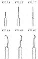
- Figs. 7A to 7C are diagrams illustrating variously implementated examples of microneedles provided at a distal end of an injector.
- Fig. 7A illustrates a short microneedle manufactured at the distal end of the injector
- Fig. 7B illustrates a long microneedle manufactured at a distal end of an injector
- Fig. 7C illustrates a microneedle, having a bevel angle formed at the distal end of the injector, manufactured by the above-described method.
- a solid microstructure contacting a distal end of a single hollow injector is formed of an epoxy polymer "SU-8 2050 photoresist (microchem)" that is a polymer having viscosity of 14,000 cSt.
- the SU-8 2050 is respectively coated on a metal or silicon substrate to a thickness of 165 ⁇ m, and then maintained at a temperature of 120 °C for 5 minutes, thereby enabling the flux of the SU-8 2050 to be maintained. Subsequently, the SU-8 2050 is contacted to a distal end of a
- the coated SU-8 2050 While slowly lowering a temperature of the substrate to 70 °C to 60 °C, the coated SU-8 2050 has viscosity enabling lifting: At this point, by lifting a lifting frame for 13 minutes at a speed of 10 ⁇ m/s, an initial solid structure having a length of 7,800 ⁇ m is formed. Before the formed initial solid structure is hardened, by processing the initial solid structure in the wind of 10 ⁇ m/s in a specific direction, a bent solid structure whose a lower portion is spaced apart by a distance of 500 ⁇ m from a distal end of a contacted injector is manufactured. As the same bent effect, the lower portion of the solid structure from the distal end of the contacted injector is spaced apart by a distance of 500 ⁇ m, and an initial solid structure is bent.
- the bent solid structure may be spaced apart from the lifting frame.
- a single solid microstructure whose an upper portion and a lower portion are vertically spaced apart from each other by a distance of 500 ⁇ m and which is bent at respective portions corresponding to a diameter of 30 ⁇ m in the upper portion, a diameter of 200 ⁇ m in the lower portion, a length of 3,000 ⁇ m, and a length of 1,500 ⁇ m is obtained at a distal end of a hollow injector, and chemical-vapor-deposited in Tollens reaction. Subsequently, the upper portion of the single solid microstructure is protected with enamel or SU-8 2050.
- Processing the enamel or SU-8 2050 on the upper portion prevents the upper portion from being plated in a subsequent process.
- the single solid microstructure is overall plated with metal and then cut by a laser and a microsaw, thereby forming a hollow microstructure.
- a surface of the solid microneedle whose the upper portion has been protected is electroplated with Ni.
- the Ni electroplating is performed by 0.206 ⁇ m/min per 1 A/dm2 for 75 minutes so that a thickness of the electroplated Ni may become 20 ⁇ m.
- the upper portions of is performed by 0.206 ⁇ m/min per 1 A/dm2 for 75 minutes so that a thickness of the electroplated Ni may become 20 ⁇ m.
- each of the structures is put into an SU-8 remover of 60 °C to 100 °C for one hour to remove the solid microstructure of the SU-8 2050, thereby obtaining a hollow microneedle contacting a hollow injector.
- the upper portion and lower portion of the single solid microstructure are vertically spaced apart from each other by a distance of 500 ⁇ m, and the single solid microstructure is bent at respective portions corresponding to a diameter of 30 ⁇ m of the upper portion, a diameter of 200 ⁇ m of the lower portion, a length of 3,000 ⁇ m, and a length of 1,500 ⁇ m.
- Figs. 8A to 8C are diagrams schematically illustrating implementation examples of bent microneedles.
- Fig. 8A illustrates a microneedle bent from a distal end of an injector
- Fig. 8B illustrates a microneedle that is manufactured by the above-described method and bent from a central position of a microneedle structure
- Fig. 8C illustrates a microneedle bent at a distal end of the microneedle structure.
- Embodiment 9 (which does not form part of the invention but represents background art that is useful for understanding the invention): manufacturing a microvalve using an overlapped microneedle structure.
- Fig. 9 is a schematic diagram illustrating an embodiment that does not form part of the invention but represents background art useful for understanding the invention, namely a microvalve using an overlapped microneedles structure.
- the microvalve includes: an internal microneedle 91 that is a hollow or solid microneedle; an external hollow microneedle 93 that is disposed surface of the internal microneedle 91, and surrounds the surface of the internal microneedle 91; and a clipping device 95 that is formed by bending a distal end of a lower portion of the external microneedle 93 toward the inside thereof.
- a distal end of a lower portion of the internal microneedle 91 may be bent toward the outside, or the distal ends of the respective bottoms of the external microneedle 93 and internal microneedle 91 may be respectively bent toward the inside and the outside, thereby forming the clipping device 95.
- a constant manufacturing condition is first fixed, and two hollow microstructures having the same external appearance are manufactured.
- one of the two manufactured microneedles is an external microneedle, and the other is inserted into the external microneedle and is an internal microneedle, thereby establishing an overlapped microneedle structure in which a constant internal interval of 5 ⁇ m to 10 ⁇ m is maintained between the two microneedles.
- a distal end of a lower portion of the internal microneedle is fixed by bending a distal end of a lower portion of the external microneedle toward the distal end of the bottom of the internal microneedle, and thus, the internal microneedle becomes an internal valve adjustment device, thereby enabling a fluid to flow into a portion which is not covered by the bent portion.
- the bent portion moves by elasticity according to the pressure intensity of a fluid to thereby obstruct or prevent the flow of the fluid, and thus serves as a fluid adjustment valve that adjusts a flow speed and a flow pressure. Therefore, for example, when the microvalve is used as a glaucoma drainage device for treating glaucoma caused by a high intraocular pressure, the pressure.
- the microvalve when used as a glaucoma drainage device for treating glaucoma caused by a high intraocular pressure, the microvalve can simplify glaucoma surgery and increase a treatment effect compared to the existing glaucoma drainage devices.
- Embodiment 10 (which does not form part of the invention but represents background art that is useful for understanding the invention): manufacturing a biosensor using an overlapped microneedle structure
- Fig. 10 is a schematic diagram illustrating an embodiment that does not form part of the invention but represents background art useful for understanding the invention, namely a biosensor using the overlapped microneedle structure.
- the biosensor includes: an internal microneedle 101 that is a hollow or solid microneedle; an external hollow microneedle 103 that is disposed at the outside of the internal microneedle 101, has the same surface curve as that of the internal microneedle 101, is spaced apart by a certain distance from a surface of the internal microneedle 101, and surrounds the surface of the internal microneedle 101; an insulator 105 that is coated on an outer surface of the internal microneedle 101; a positive terminal 107 that is connected to a distal end of the internal microneedle 101; a negative terminal 109 that is connected to a distal end of the external microneedle 103; and a measurement device (not shown) that measures a resistance, a current, or a voltage which is generated by a power source.
- a constant manufacturing condition is first fixed for manufacturing an overlapped microneedle, and thus, two hollow microstructures having the same external appearance are manufactured.
- Parylene KISCO, diX N in Japan
- CVD chemical-vapor-deposited
- the other internal microneedle is inserted into an external microneedle, thereby establishing an overlapped microneedle structure.
- a positive power source and a negative power source are connected to respective distal ends of the internal microneedle and external microneedle of the overlapped microneedle structure, and a voltmeter and an ohmmeter (Yokogawa 3201 tester, Japan) are connected to the overlapped microneedle structure (see Fig. 10 ).
- the inventors adheres a biomarker such as glucose oxidase (GOx) to a distal end in an upper portion of the overlapped microneedle, thereby manufacturing a biosensor for measuring blood glucose contents of a body.
- a biomarker such as glucose oxidase (GOx)
- the hollow microneedle may be directly implanted into skin without collecting blood of a patient, thus enabling the measurement of blood sugar reacting with interstitial fluid (ISF) without fear of pain and blood collection.
- ISF interstitial fluid
Landscapes
- Health & Medical Sciences (AREA)
- Engineering & Computer Science (AREA)
- Life Sciences & Earth Sciences (AREA)
- Animal Behavior & Ethology (AREA)
- General Health & Medical Sciences (AREA)
- Public Health (AREA)
- Veterinary Medicine (AREA)
- Mechanical Engineering (AREA)
- Dermatology (AREA)
- Biomedical Technology (AREA)
- Heart & Thoracic Surgery (AREA)
- Chemical & Material Sciences (AREA)
- Manufacturing & Machinery (AREA)
- Hematology (AREA)
- Anesthesiology (AREA)
- Medical Informatics (AREA)
- Surgery (AREA)
- Vascular Medicine (AREA)
- Ophthalmology & Optometry (AREA)
- Physics & Mathematics (AREA)
- Pharmacology & Pharmacy (AREA)
- Microelectronics & Electronic Packaging (AREA)
- Analytical Chemistry (AREA)
- Medicinal Chemistry (AREA)
- Epidemiology (AREA)
- Chemical Kinetics & Catalysis (AREA)
- Optics & Photonics (AREA)
- Nuclear Medicine, Radiotherapy & Molecular Imaging (AREA)
- Pathology (AREA)
- General Chemical & Material Sciences (AREA)
- Biophysics (AREA)
- Molecular Biology (AREA)
- Media Introduction/Drainage Providing Device (AREA)
- Medicinal Preparation (AREA)
Description
- The present invention relates to a method for manufacturing a hollow microneedle having a variable appearance as defined in claim 1 and the hollow microneedle manufactured by the same.
- Unlike the existing needles, micronneedles pass through skin without pain and do not leave an external injury. In order to implant a microneedle into skin without pain, a diameter of an upper portion of the microneedle is important for the minimum sharpness. Also, the microneedles needs to pass through a stratum corneum of 10 µm to 20 µm serving as the biggest obstacle in skin, and thus are required to have sufficient physical hardness. However, since the thicknesses and elasticity of skins, efficiency of transdermal drug delivery, the viscosities of drugs, and the amount of administered drugs differ according to species, races, individuals, and skin regions, a method for manufacturing a microneedle having a variable appearance is required.
- A hollow silicon microneedle having a bevel angle was developed by Nanopass company in a secondary etching method which is an advanced etching method (
WO 0217985 WO 2005049107 ; Gardeniers, Han J.G.E, et al., Silicon Micromachined Hollow Microneedles for Transdermal Liquid Transport, Journal of microelectro-chemical systems, 12(6): 855-862(2003)). Griss and Stemme of Stanford University in the USA have proposed a side-opened hollow silicon microneedle and a cross-type hollow silicon microneedle (P. Griss and G. Stemme, Side-Opened Out-of-Plane Microneedles for Microfluidic Transdermal Liquid Transfer, Journal of microelectro-chemical systems, 12(3): 296301 (2003);U.S. Patent Publication No. 2004-0267205 ). - Prausnitz of Georgia University in the USA proposed a method that forms a mold with a laser and manufactures a hollow microneedle by using deposition and electro-plating (Prausnitz, M.R. et al., Hollow Metal Microneedles for Insulin Delivery to Diabetic Rats IEEE, Transaction on biomedical engineering, 52(5): 909-915 (2005)). However, the hollow microneedle manufactured by the method has problems in diameter and length similarly to the above-described methods. Also, Prausnitz of Georgia University in the USA proposed a new-type hollow glass microneedle that has a bevel angle and a length of about 900 µm formed by lengthening a glass micropipette at a high temperature ("Microinfusion Using Hollow Microneeldes", Pharmaceutical Research, Vol. 23, No. 1, January 2006 and "Mechanism of fluid infusion during microneedle insertion and retraction", Journal of Controlled Release, 2006, 357361). As described above, various hollow microneedles have been developed. However, since the hollow microneedles are manufactured as standardized products to have uniform appearances in length, diameter, aspect ratio, sharpness, and bevel angle, it is difficult for the products of currently standardized hollow microneedles to deliver drugs through various regions of a human body and perform efficient conversion according to drugs having various viscosities, and the medical application of the hollow microneedles are limited compared to the existing hypodermic needle. Therefore, it is continuously required manufacturing technology in which the strength, sharpness, bevel angle, and bending of a hollow microneedle necessary for passing through skin may be adjusted depending on regions of skin, the for passing through skin may be adjusted depending on regions of skin, the length of the hollow microneedle may be adjusted according to a degree by which the hollow microneedle passes through skin, and, by adjusting the diameter of the hollow microneedle according to the change in the viscosity and administration amount of treated drug, the external appearance of the hollow microneedle may be flexibly adjusted according to the application method of drug delivery and body material sampling including blood collection.
-
WO 2009/072830 A2 discloses a hollow microneedle array which includes a needle part having a plurality of hollow microneedles and a substrate part supporting the needle part. The needle includes an upper portion inserted into a skin and a base portion communicated with an upper portion and supporting the upper portion. An upper end of the upper portion has such an outer diameter that reduces pain upon penetration into the skin. A diameter of the upper portion smoothly increases as it goes to the other end thereof so as to reduce pain upon penetration of the skin. An aspect ratio of the diameter of the upper end of the upper portion to a length of the needle is high to enable deep penetration into the skin. A diameter of the base portion generally exponentially increases as it goes to a lower end of the base portion so as to increase total strength of the needle in both longitudinal and lateral directions. Further, the needle is made of biocompatible metal having good mechanical properties. -
WO 2006/018642 A1 discloses a method of manufacturing microneedles, the method comprising (i) depositing a substance onto a first surface and (ii) forming a solid needle-like shape from the substrate. The substance may be deposited in non-solid form and subsequently solidified. A method of providing an array of such microneedles is also described. - In the specification, a plurality of papers and patent documents are referenced, and citations thereof are indicated. The overall disclosure of each of the cited paper and patent document is inserted as a reference into the specification, and thus, the level of the technical field of the present invention and the configuration and function of the present invention are clearly described.
- The present invention is as set out in the independent claims.
- In view of the above, examples of the present disclosure seek to provide a method for manufacturing a hollow microstructure whose an external appearance (for example, an effective length, an internal diameter and external diameter of an upper portion, a diameter, hardness, sharpness, bevel angle, and aspect ratio of a lower portion, and bending of lower portion) may be varied by adjusting a thickness of a substrate, a diameter of a lifting frame, a lifting speed, a lifting time, a temperature for molding a microneedle, a bevel angle for cutting.
- Further, examples of the present disclosure seek to provide the hollow microstructure, having various external appearances, manufactured by the method.
- In accordance with an aspect of the present disclosure, there is provided a method for manufacturing a hollow microstructure having a varied appearance.
- Certain embodiments, which do not form part of the invention but represent background art that is useful for understanding the invention, provide a method that includes: (a) coating a solution of a viscous material on a surface of a substrate; (b) bringing the solution of the viscous material into contact with a frame; (c) lifting-the substrate, the frame, or the substrate and the frame for the contacted frame and substrate to be spaced apart from each other to thereby manufacture a solid microstructure; (d) depositing metal on the solid microstructure; (e) protecting a top of the metal-deposited solid microstructure, and metal-plating a surface of the microstructure; (f) removing the solid microstructure to obtain a hollow microstructure; (g) manufacturing a microneedle manufactured at a distal end of an injector; and (h) manufacturing a bent microneedle, wherein a coating thickness of the viscous material, a diameter of the frame, a temperature of the viscous material, a lifting speed, a plating thickness, or combination thereof is adjusted.
- In accordance with other embodiments, which do not form part of the invention but represent background art that is useful for understanding the invention, there is provided a hollow microneedle manufactured by the above-described method.
- The inventors have made an effort to develop an improved process that can manufacture a hollow microneedle having a variable appearance. As an result, the inventors have realized that a hollow microneedle having characteristics (for example, an effective length, an internal diameter and external diameter of an upper portion, a diameter, hardness, sharpness, bevel angle, and aspect ratio of a lower portion, and bending) that are more simply and quickly adjusted at lower manufacturing cost, when adjusting a coating thickness of a viscous material, a diameter of a frame, a temperature of the viscous material, a lifting speed, and a lifting time, a plating thickness, a cut bevel angle, or combination thereof.
- The method of certain embodiments, which do not form part of the invention but represent background art that is useful for understanding the invention, will be described below in detail by operation.
- Operation (a): coating a solution of a viscous material on a surface of a substrate
- A viscous material is first coated on a surface of a substrate, for manufacturing a solid microstructure that is a mold of a hollow microneedle.
- A material, used for manufacturing the solid microstructure that is the mold of the hollow microneedle, is a viscous material. In the specification, the term "viscous material" denotes a material that has a fluid type which has low viscosity at a certain temperature or higher but, when approaching a glass transition temperature by lowering the certain temperature, has high viscosity. A viscous material, used in the specification, includes an acryl-based polymer, an amide-based polymer, an acetyl-based polymer, a vinyl-based polymer, an epoxy-based polymer, a silicon-based polymer, a sulfonic resin, a polycarbonate-based polymer, or a copolymer thereof, but is not limited thereto. All viscous materials which are commonly used in the art may be used.
- The viscous material used in the specification has viscosity when the viscous material becomes a fluid. The viscosity may be variously changed according to the kind, concentration, and temperature of viscous material and an organic solvent, and may be adjusted. When the viscous material becomes a fluid, the viscous material has viscosity of 200,000 cSt or less.
- Changing a viscous material to a fluid may be performed by various methods known in the art. For example, when a viscous material is a liquid polymer, an operation of changing the viscous material to a fluid is not needed. When a viscous material is a thermoplastic resin, by heating the viscous material at a temperature equal to or higher than a melting point and then lowering the temperature to approach the glass transition temperature, the viscous material has viscosity. Also, by dissolving a viscous material in a suitable organic solvent (for example, anhydrous or hydrous low alcohol of 1-4 carbon atoms, acetone, ethyl acetate, chloroform, 1,3-butylene glycol, hexane, diethyl ether, butyl acetate, etc.), the viscous material may become a fluid.
- In the specification, the term "coating" denotes that a layer of a specific material having a certain thickness is formed on a target surface. A substrate providing a surface is formed of polymer, organic chemical material, metal, ceramic, semiconductor, or the like.
- A coating thickness of a solution of a viscous material used may be adjusted within a range from 10 µm to 500 µm, a range from 50 µm to 200 µm, or a range from 75 µm to 165 µm. The coating thickness affects various appearance factors (i.e., an effective length, an internal diameter, an external diameter, sharpness, an aspect ratio, etc.) of a finally manufactured hollow microneedle, and particularly, acts as a variable that changes an effective length, diameter, and sharpness of a solid microneedle, namely, an effective length, sharpness, external diameter, and internal diameter of a hollow microneedle. In the range of the coating thickness, as a coating thickness increases, an external diameter and internal diameter of a hollow microneedle increase, an effective length increases, and sharpness decreases.
- A viscous material used may be is a polymer compound which is removed by an organic solvent.
- In the specification, the polymer compound removed by the term "organic solvent" is a natural or synthetic compound having a molecular weight of 5,000 or more, and denotes a compound having solubility to an organic solvent.
- A polymer compound used should be easily removed after metal-deposition and plating for manufacturing a hollow microneedle, and thus, the inventors have removed the polymer compound (which is a component of a metal-plated solid microstructure) by dissolving the polymer compound in an organic solvent.
- The polymer compound used may be acrylonitrile styrene (AS), polyamide, polyethylene, polyester, polyacryl, polyacetylene, styrene, teflon, polyvinyl chloride, polyurethane, nylon, sulfonic resin, or epoxy polymer. For example, the polymer compound may be an epoxy polymer.
- The organic solvent used may include benzene, toluene, xylene, hexane, ester, acetone, alcohol, and amine, but is not limited thereto. All polar or nonpolar solvents, which are commonly used to dissolve a polymer compound, may be used. For example, when an epoxy polymer is used as the polymer compound, N-methyl pyrrolidine (NMP) may be used as a solvent.
- Operation (b): bringing the solution of the viscous material into contact with a frame
- In the specification, after coating a viscous material (for example, a polymer compound) changed to a fluid, a lifting frame is brought into contact with an interface of the viscous material. A diameter of the lifting frame may be changed, in which case the diameter of the lifting frame may be adjusted within a range from 1 µm to 1,000 µm or adjusted within a range from 10 µm to 500 µm. The diameter of the lifting frame affects various appearance factors (i.e., an effective length, an internal diameter, an external diameter, sharpness, an aspect ratio, etc.) of a finally manufactured hollow microneedle, and particularly, acts as a variable that changes an effective length, diameter, and sharpness of a solid microstructure, namely, an effective length, sharpness, external diameter, and internal diameter of a hollow microstructure. As the diameter of the lifting frame increases, an external diameter and internal diameter of a hollow microneedle increase, an effective length increases, and sharpness decreases.
- A frame used in the specification may be patterned. In this case, the pattern may be formed from a single array to a multi-array, and a pitch between frames may be 1 µm to 2,000 µm. As another example, the pitch between the frames may be 100 µm to 1,000 µm.
- Operation (c): lifting the substrate, the frame, or the substrate and the frame for the contacted frame and substrate to be spaced apart from each other to thereby manufacture a solid microstructure
- The term "solid microstructure" used in the specification denotes a microstructure that is manufactured as one body without a hollow space and a mold of a hollow microneedle.
- By lowering a temperature of a viscous material (for example, polymer material) changed to a fluid to approach the glass transition temperature, viscosity increases. In operation (c), the viscosity affects various appearance factors (i.e., an effective length, an internal diameter, an external diameter, sharpness, an aspect ratio, etc.) of a finally manufactured hollow microneedle, and particularly, acts as a variable that changes an effective length of a solid microstructure and an effective length of a hollow microstructure. In operation (c), as the viscosity of the viscous material increases, an effective length of a hollow microstructure increases.
- The temperature of the viscous material may be adjusted within a range from a glass transition temperature to 120 °C, thereby adjusting viscosity of the viscous material.
- In the specification, the term "glass transition temperature" denotes a temperature at which a fluid material having viscosity is solidified. Therefore, it is impossible to perform a lifting process on a solidified material at a temperature lower than the glass transition temperature. When a temperature is too high, viscosity decreases, and thus, it is difficult to perform a lifting process. As a result, it is unable to manufacture a solid microstructure.
- The viscosity of the viscous material which is adjusted in operation (c) may be 50 Poise to 10,000 Poise, 80 Poise to 8,000 Poise, or 100 Poise to 6,500 Poise.
- In the specification, the term "separation" denotes increasing a distance between contacted elements to broaden a gap between the contacted elements. The inventors have manufactured a solid microstructure by lifting (moving upward) a frame contacting a viscous material, but is not limited thereto. As another example, the solid microneedle may be manufactured by a method that downward moves a substrate to separate the substrate from a frame when the frame is fixed, and a method that upward and downward moves a frame and a substrate simultaneously to separate the substrate from the frame.
- By adjusting a lifting speed of a polymer having viscosity, various appearance factors (i.e., an effective length, an internal diameter, an external diameter, sharpness, an aspect ratio, etc.) of a finally manufactured hollow microneedle may be adjusted, and particularly, an effective length of a solid microstructure and an effective length of a hollow microneedle may be adjusted. As the lifting speed increases, the effective length of the hollow microneedle increases.
- In the specification, the term "lifting speed" includes an upward or downward moving speed of a frame or a substrate and moreover a relative speed at which the frame and the substrate is spaced apart from each other when the frame and the substrate simultaneously move upward and downward.
- The lifting speed used in the specification is 0.1 µm/s to 2,000 µm/s, and for example, may be 1 µm/s to 1,000 µm/s. A length of the final solid microstructure may be adjusted by a correlation (multiplication) between a lifting speed and a lifting time. For example, the multiplication of the lifting speed (µm/s) and lifting time (s) may be 500 µm to 10,000 µm, 500 µm to 5,000 µm, or 1,000 µm to 3,000 µm.
- Operation (d): depositing metal on the solid microstructure
- Metal is deposited on a manufactured solid microstructure, thus more facilitating a metal-plating reaction for manufacturing a hollow microneedle after the deposition.
- In the specification, the term "deposition" denotes that a material to be coated is vaporized or sublimated for enhancing the mechanical intensity thereof in a physical method or a chemical method, and thus coagulated on a substrate surface in units of an atom or a molecule, thereby forming a film. All physical vapor depositions and chemical vapor depositions which are commonly used in the art may be used.
- The metal for deposition may be stainless steel, Al, Cr, Ni, Au, Ag, Cu, Ti, Co, or an alloy thereof. For example, Ag may be chemical-vapor-deposited in Tollens reaction.
- Ag which is precipitated through a reduction reaction using Tollens reagent "Ag2O+NH4OH+H2O" may be deposited on a solid microstructure. The Tollens reaction does not need a heating process, a pressurizing process, and a separate cooling process unlike physical vapor deposition using sputtering, and thus is more favorable to metal deposition on a target surface.
- Operation (e) protecting an upper portion of the metal-deposited solid microstructure and metal-plating a surface of the microstructure
- In the specification, by plating a solid microstructure, the base of a hollow microneedle may be provided. Various appearance factors (i.e., an internal diameter and hardness) of a finally manufactured hollow microneedle may be varied by adjusting a plating thickness. As the plating thickness increases, an external diameter and hardness of the hollow microneedle increase, an effective length increases. The plating thickness used may be 5 µm to 100 µm, and for example, may be 10 µm to 50 µm.
- A plating material used, for example, may include Ni, stainless steel, Al, Cr, cobalt-based alloy, Ti, or an alloy thereof, but is not limited thereto. The plating material is metal applicable to a body, and is metal that does not have toxicity, carcinogenicity, and rejection to a body, is good in mechanical properties such as tension intensity, elastic modulus, and wear resistance, and has anticorrosion for enduring a corrosive environment in a body. As the plating material, all metals known in the art may be used.
- The plating metal may be stainless steel, Al, Cr, Ni, Au, Ag, Cu, Ti, Co, or an alloy thereof. For example, the plating metal may be Ni.
- Operation (f) removing the solid microstructure to obtain a hollow microstructure
- After the plating process, by removing the solid microneedle, a hollow microneedle may be manufactured. The solid microneedle may be removed by dissolving the solid microneedle in an appropriate organic solvent or by burning the solid microneedle, or may be removed physically. The solid microneedle is removed using the appropriate organic solvent.
- To easily pass through skin, an antifriction such as glycerin may be coated on a metal microneedle. An anticoagulation solution such as citrate or EDTA may be coated on a hollow metal microneedle, for preventing blood coagulation in collecting blood.
- The method may further include cutting the top of the hollow microneedle through adjustment within a bevel angle of 0 degrees to 60 degrees.
- In the specification, by providing the bevel angle of the top of the hollow microneedle, the internal diameter and sharpness of the hollow microneedle can increase. As a method of adjusting the bevel angle, all precise cutting methods which are commonly used in the art may be used, and for example, a laser or a microsaw (dicing saw) may be used for cutting. By adjusting the bevel angle, various cross-sectional areas of an internal diameter and sharpness suitable for use may be provided. The bevel angle is adjusted within a range from 0 degrees to 90 degrees, and for example, may be adjusted within a range from 0 degrees to 60 degrees.
- In the hollow microstructure, a relationship between an effective length, the lifting speed, a diameter of the lifting frame, and the coating thickness of the viscous material may be expressed as Formula.

where Y denotes the effective length (µm) of the hollow microstructure, x denotes the internal diameter (µm) of the hollow microstructure, and b denotes "(diameter (µm) of lifting frame + coating thickness (µm) of viscous material)/50". - A hollow microstructure having various appearances may be manufactured by adjusting an effective length, a lifting speed, a lifting frame, and a coating thickness, manufacturing temperature, coating thickness, and bevel angle cutting of a viscous material. The inventors have repeatedly performed an experiment in various conditions so as to build a manufacturing condition for forming a predictable appearance, and thus established a relationship between an effective length and internal diameter of a hollow microstructure, a diameter of a lifting frame, and a coating thickness of a viscous material. Accordingly, by simply adjusting a manufacturing condition for obtaining various effective length and/or internal diameters based on the purpose of production, the microstructure may be manufactured to have a desired appearance. By using Formula, a microstructure having various appearances and uses may be manufactured depending on the necessary using the same production line. Accordingly, economical and efficient manufacturing may be enabled.
- The hollow microstructure may be a single-type hollow microneedle that is connected to a top of a hollow injector. In the specification, the term "hollow injector" denotes a hollow injector, having on bevel angle, which is commonly used to deliver drugs or collect a fluid sample in the art.
- By bringing the viscous material (coated on the substrate) into contact with the distal end of the top of the hollow injector instead of the lifting, frame, a hollow microneedle connected to the top of the hollow injector may be manufactured. When the hollow microneedle is manufactured by the method, an injector for delivering drugs and collecting a bio sample through transdermal administration may be produced simply and efficiently.
- According to an implementation example of the present invention, the method includes obtaining a bent microneedle structure by sending wind in a specific direction before the solid microneedle which is formed in operation of lifting the contacted substrate and frame to be spaced apart from each other is hardened.
- In the specification, the term "bending" denotes a ratio of a vertical distance from the top of the microneedle to the substrate surface disposed at the bottom of the microneedle and a distance in which the center of the microneedle maximally deviates from on a vertical line from the top to the bottom of the microneedle. A bending rate is 20:1 to 2:1, and for example, may be 10:1 to 2:1. According to the present invention, the bending rate and bending position of the microneedle may be variously varied by adjusting a winding speed, a winding time, a winding direction, and a winding position in the lifting operation. In the method of the present invention, the winding speed is 3 µm/s to 70 µm/s. For example, the winding speed may be 5 µm/s to 50 µm/s, or 7 µm/s to 20 µm/s.
- In accordance with certain embodiments of the present invention, there is provided a hollow microneedle manufactured by the method used in the present invention.
- One of advantages of certain embodiments, which do not form part of the invention but represent background art that is useful for understanding the invention, is to enable the external appearance of the hollow microneedle to be variously varied so as to be suitable for each use. The sharpness, top diameter, bottom diameter, length, and aspect ratio of the solid microstructure may be adjusted through operations (a) to (d) of the method of certain embodiments, which do not form part of the invention but represent background art that is useful for understanding the invention. The method of embodiments of the present invention includes sending wind in a specific direction before the solid microstructure formed in the lifting operation is hardened, and thus, the bending rate and bending position of the hollow microneedle may be adjusted.
- In the specification, the term "top" denotes one distal end of the microneedle having the minimum diameter, and the term "bottom" denotes an under distal end of the microneedle contacting the substrate.
- In the specification, the term "effective length" denotes a vertical length, from the top of the microneedle to the substrate surface disposed at the bottom of the microneedle. In the specification, the term "aspect ratio" denotes a ratio (height to diameter at base) of the maximum diameter of the microneedle to the vertical length from the top of the microneedle to the substrate surface disposed at the bottom of the microneedle.
- In the specification, the term "sharpness" denotes a degree by which a diameter from the bottom to the top of the microneedle decreases. That is, as sharpness increases, a degree of decrease in the diameter is high.
- In the hollow microneedle, an effective length may be 150 µm to 6,000 µm, an external diameter of an upper portion is 40 µm to 200 µm, an internal diameter of the top is 10 µm to 100 µm, an external diameter of a lower portion is 200 µm to 1,000 µm, an internal diameter of the bottom is 150 µm to 950 µm, a difference between the internal diameter and external diameter of the top and bottom is 10 µm to 50 µm, and an aspect ratio is 1:10 to 1:30. As another example, in the hollow microneedle, an effective length is 1,000 µm to 2,000 µm, an external diameter of an upper portion is 30 µm to 100 µm, an internal diameter of the top is 20 µm to 90 µm, an external diameter of a lower portion is 200 µm to 500 µm, an internal diameter of the bottom is 170 µm to 470 µm, a difference between the internal diameter and external diameter of the top and bottom is 20 µm to 30 µm, and an aspect ratio is 1:15 to 1:20. Especially, the aspect ratio may be 1:15 to 1:20.
- The external diameter and internal diameter of the top, the internal diameter, thickness, length, sharpness, and aspect ratio of the bottom, the bending degree, and the bending position may be freely varied according to purposes.
- The hardness of the hollow microneedle may be 0.1 Newton (N) to 5 N.
- In the specification, the term "hardness" denotes a force that resists to the change in a shape when an external force is applied to the solidified hollow microneedle. A hardness value enabling a microneedle to pass through skin is about 0.06 N. The hollow microneedle has a hardness value far greater than 0.06 N, and thereby easily passes through all skins of a body, thus enabling the administration of drugs.
- In an embodiment that does not form part of the invention but represents background art useful for understanding the invention there is provided a microvalve which includes: an internal microneedle, the internal microneedle being a hollow or solid microneedle; an external microneedle disposed at outside of the internal microneedle, spaced apart by a certain distance from a surface of the internal microneedle to surround the surface of the internal microneedle, and having the same surface curve as the internal microneedle, the external m icroneedle being a hollow microneedle; and a clipping device formed by bending a distal end of a lower portion of the external microneedle toward inside, bending a distal end of a lower portion of the internal microneedle toward outside, or respectively bending the distal ends of the respective bottoms of the external microneedle and internal microneedle toward the inside and the outside.
- A space having a certain volume, which is disposed between the external microneedle and the internal microneedle, becomes a path through which a fluid flows. A microneedle, which acts as an internal valve by elasticity of the bent portion, moves according to the pressure intensity of a fluid to thereby obstruct or prevent the flow of the fluid, and thus acts as a fluid adjustment valve that adjusts a flow speed and a flow pressure.
- In the specification, the term "valve" denotes a device that adjusts the flow or pressure of a fluid by blocking an open/close or partial path. The sharpness, top diameter, bottom diameter, length, aspect ratio, bending rate, and bending position of the microstructure may be varied by adjusting the coating thickness, manufacturing temperature, lifting speed, lifting time, plating thickness, bevel angle, winding speed, and winding position of the viscous material. Therefore, two microneedles having the same surface curve are manufactured by accurately varying an external appearance, and, with the two microneedles as an internal microneedle and an external microneedle, an overlapped microneedle having a certain space between the internal microneedle and the external microneedle may be manufactured. The space between the microneedles becomes a path of a fluid, and the flow of the fluid is adjusted by a clipping device disposed at a distal end of a lower portion of each of the two microneedles.
- In the specification, the term "microvalve" denotes a device that is disposed in a moving path of a fine fluid, and accurately adjusts a flow pressure and an amount of moved fluid by overall or partially blocking the flow of the fluid. When the overlapped microneedle is implanted into a film surrounding a fluid, the fluid inside the film may flow along the space of the overlapped microneedle, and the microvalve may accurately adjust the discharge of the fluid.
- The microvalve may be a glaucoma drainage device for treating glaucoma. In the specification, the term "glaucoma" denotes eye disease in which as an intraocular pressure becomes higher than a normal pressure (21 mmHg or more), the intraocular pressure presses an optic nerve to damage or destroy the optic nerve, and thus, sight is reduced or lost. The intraocular pressure is determined by equilibrium between production of tail water and a resistance to the outflow of the tail water. Generally, the rising of the intraocular pressure is caused by the increase in a resistance to the outflow of the tail water. Therefore, the smooth outflow of the tail water is important for treating glaucoma. The overlapped microneedle does hardly damage a film surface, and discharges a fluid surrounded by a film to the outside in a flow pressure and an amount that are accurately and finely adjusted. Accordingly, the overlapped microneedle can be usefully used to treat glaucoma through the outflow of tail water.
- In accordance with another embodiment that does not form part of the invention but represents background art useful for understanding the invention there is provided a biosensor which includes: (a) an internal microneedle, the internal microneedle being a hollow or solid microneedle; (b) an external microneedle disposed at outside of the internal microneedle, spaced apart by a certain distance from a surface of the internal microneedle to surround the surface of the internal microneedle, and having the same surface curve as the internal microneedle, the external microneedle being a hollow microneedle; (c) an insulator coated on an outer surface of the internal microneedle or an inner surface of the external microneedle; (d) a positive terminal connected to a distal end of the internal microneedle; a negative terminal connected to a distal end of the external microneedle; and (e) a measurement device for measuring a resistance, a current, or a voltage which is generated across the positive and negative terminals.
- In the specification, the term "insulator" denotes a material that shows a resistance to the flow of a current, and thus has properties difficult to transfer electricity. The insulator is disposed in the space between the internal microneedle and external microneedle of the overlapped microneedle, and, after a distal end of an upper portion of the overlapped microneedle is implanted into a material to analyze, a voltage is applied to the positive terminal and negative terminal connected to a distal end of a lower portion of the overlapped microneedle. At this point, by measuring a generated voltage or resistance, the electrical characteristic of a material to measure may be detected.
- The biosensor may further include a biomarker connected to a distal end of an upper portion of the internal microneedle and a distal end of an upper portion of the external microneedle.
- In the specification, the term "biomarker" denotes a material that becomes an indicator for determining a biological condition of a living thing. The biomarker is adhered between the distal ends of the overlapped microneedle, and, after the biomarker is implanted into skin, by measuring a voltage generated across the two terminals, a biological condition of a living thing can be detected. For example, the biomarker is a protein. In detail, when glucose oxidase (GOx) is used as the biomarker, the overlapped microneedle with the glucose oxidase adhered thereto is implanted into skin of a target thing, and then, by measuring the change in a voltage, a glucose concentration in blood may be measured on the basis of the measured change in the voltage. Accordingly, a simple procedure may be performed that implants a simple device into a patient and performs measurement without blood collection and pain, thereby enabling the high-reliability measurement of blood sugar at low cost.
- The features and advantages of certain embodiments, which do not form part of the invention but represent background art that is useful for understanding the invention, are as follows.
- Certain embodiments, which do not form part of the invention but represent background art that is useful for understanding the invention, provide a method that manufactures a hollow microneedle having various external appearances by adjusting a coating thickness of a viscous material, a manufacturing temperature, a lifting speed, a lifting time, a plating thickness, and cutting of a bevel angle in a manufacturing process. Such a method has not been employed at all.
- Moreover, in accordance with certain embodiments, which do not form part of the invention but represent background art that is useful for understanding the invention, a hollow microneedle having a desired external appearance may be simply and quickly manufactured at the low manufacturing cost.
- Moreover, in accordance with certain embodiments, which do not form part of the invention but represent background art that is useful for understanding the invention, by manufacturing a hollow microneedle having characteristics of various external appearances, provided is a hollow microneedle that may deliver drugs and collect blood irrespective of species, races, individuals, regions of skin, and the viscosity and amount of the drugs.
- Moreover, in accordance with certain embodiments, which do not form part of the invention but represent background art that is useful for understanding the invention, the hollow microneedle may be manufactured in an array type, and manufactured as a single type microneedle that is coupled to a distal end of an injector compatible with a syringe.
- Moreover, in accordance with the present invention, a microneedle in which the degree and position of bending may be adjusted is manufactured by the method of the present invention.
- Moreover, in accordance with an embodiment that does not form part of the invention but represents background art useful for understanding the invention by manufacturing a plurality of microneedles having the same surface curve in a method of adjusting an external appearance of the microneedle, a microvalve and a biosensor having the microneedle type may be manufactured by a structure in which the microneedles overlap. The mircovalve in which a flow pressure is finely adjusted in a simple structure and at low cost and the biosensor that reliably detects a target material from a body may be usefully used.
-
-
Figs. 1A and 1B are views schematically illustrating detailed implementation examples of microneedles that are manufactured by adjusting a polymer coating thickness;
implementation examples of microneedles that are manufactured by adjusting a diameter of a lifting frame; -
Figs. 3A and 3B are views schematically illustrating detailed implementation examples of microneedles that are manufactured by adjusting a temperature of a polymer; -
Figs. 4A and 4B are views schematically illustrating detailed implementation examples of microneedles that are manufactured by adjusting a lifting speed; -
Figs. 5A and 5B are views schematically illustrating detailed implementation examples of microneedles that are manufactured by adjusting a plating thickness; -
Figs. 6A and 6B are views schematically illustrating detailed implementation examples of microneedles that are manufactured by adjusting a bevel angle of an upper portion; -
Figs. 7A to 7C are views schematically illustrating implementation examples of microneedles manufactured at a distal end of an injector,Fig. 7A is a view schematically illustrating a detailed implementation example of a short microneedle manufactured at the distal end of the injector,Fig. 7B is a view schematically illustrating a detailed implementation example of a long microneedle manufactured at a distal end of an injector, andFig. 7C is a view schematically illustrating a detailed implementation example of a microneedle, having a bevel angle, manufactured at a distal end of an injector; -
Figs. 8A to 8C are views schematically illustrating implementation examples of bent microneedles,Fig. 8A is a view schematically illustrating a detailed implementation example of a microneedle bent from a distal end of an injector,Fig. 8B is a view schematically illustrating a detailed implementation injector,Fig. 8B is a view schematically illustrating a detailed implementation example of a microneedle bent from a central position of a microneedles structure, andFig. 8C is a view schematically illustrating a detailed implementation example of a microneedle bent at a distal end of a microneedle structure; -
Fig. 9 is a schematic view illustrating an example that does not form, part of the invention but represents background art useful for understanding the invention, namely a microvalve using an overlapped microneedle structure; and -
Fig. 10 is a schematic view illustrating an example that does not form part of the invention but represents background art useful for understanding the invention, namely a biosensor using the overlapped microneedle structure. - Hereinafter, certain embodiments, which do not form part of the invention but represent background art that is useful for understanding the invention, will be described in more detail. It is obvious to those skilled in the art that the scope of the present invention is not limited by the described embodiments.
- Embodiment 1 (which does not form part of the invention but represents background art that is useful for understanding the invention): varying an external appearance of a microneedle by adjusting a coating thickness of a polymer solution.
- A solid microstructure is formed of an epoxy polymer "SU-8 2050 photoresist (microchem)" that is a polymer having viscosity of 14,000 cSt. SU-8 2050 is respectively coated on a metal or silicon substrate to a thickness of 75 µm and 165 µm, and then maintained at a temperature of 120 °C for 5 minutes, thereby enabling the flux of SU-8 2050 to be maintained. Subsequently, the SU-8 2050 is contacted to a 3×3 patterned frame having a diameter of 200 µm. While slowly lowering a temperature of the substrate to 70 °C to 60 °C, the coated SU-8 2050 has viscosity enabling lifting. At this point, by lifting a lifting frame for 5 minutes at a speed of 10 µm/s, as illustrated in
Figs. 1A and 1B , an initial solid structure having a length of 3,000 µm is formed. By increasing a second lifting speed or cutting, the initial solid structure may be spaced apart from the lifting frame. - As a result, in an initial coating thickness of 75 µm, a solid microstructure is formed to have a diameter of 30 µmin upper portion thereof, a diameter of 200 µmin lower portion thereof, and a length of 1,500 µm, and chemical-vapor-deposited in Tollens reaction. In an initial coating thickness of 165 µm, a solid microstructure is formed to have a diameter of 40 µmin upper portion thereof, a diameter of 300 µm in lower portion thereof, and a length of 2,000 µm, and chemical-vapor-deposited in Tollens reaction. Subsequently, the top of each of the solid microneedles is protected with enamel or SU-8 2050. Processing the enamel or the SU-8 2050 on the top prevents the top from being plated in a subsequent process. The solid microstructure is overall plated with metal and then cut by a laser and a microsaw, thereby forming a hollow microstructure.
- Subsequently, a surface of the solid microneedle whose the top has been protected is electroplated with nickel (Ni). The Ni electroplating is performed by 0.206 µm/min per 1 A/dm2 for 75 minutes so that a thickness of the electroplated Ni may become 20 µm. The electroplated structure is put into an SU-8 remover (microchem) of 60 °C to 100 °C for one hour to remove the solid microstructure of SU-8 2050 and sealed enamel, thereby obtaining a hollow microneedle. In the obtained hollow microneedle, a hollow microneedle is manufactured to have an external diameter of 70 µm of an upper portion, an internal diameter of 30 µm in the upper portion thereof, a diameter of 200 µm of a lower portion, and a length of 1,500 µm from the initial coating thickness of 75 µm, and a hollow microneedle is manufactured to have an external diameter of 100 µm of an upper portion, an internal diameter of 60 µm of the top, a diameter of 300 µm of a lower portion, and a length of 2,000 µm from the initial coating thickness of 165 µm. The hardness of the manufactured hollow microneedle indicates a value of 1-2N, which is a value far greater than 0.06 N that is a hardness value enabling the hollow microneedle to pass through skin.
- Embodiment 2 (which does not form part of the invention but represents background art that is useful for understanding the invention): varying an external appearance of a microneedle by adjusting a diameter of a lifting frame.
- A solid microstructure is formed of an epoxy polymer "SU-8 2050 photoresist" that is a polymer having viscosity of 14,000 cSt. SU-8 2050 is coated on a metal or silicon substrate to a thickness of 75 µm, and then maintained at a temperature of 120 °C for 5 minutes, thereby enabling the flux of the SU-8 2050 to be maintained. Subsequently, the SU-8 2050 is contacted to a 3×3 patterned frame having a diameter of 200 µm and a 3×3 patterned frame having a diameter of 500 µm, respectively. While slowly lowering a temperature of the substrate to 70 °C to 60 °C, the coated SU-8 2050 has viscosity enabling lifting.
- At this point, by lifting a lifting frame for 5 minutes at a speed of 10 µm/s, as illustrated in
Figs. 2A and 2B , an initial solid structure having a length of 3,000 µm is formed. By increasing a second lifting speed or cutting, the initial solid structure is spaced apart from the lifting frame. As a result, by a lifting frame having an initial diameter of 200 µm, a solid microstructure is formed to have a diameter of 30 µm in an upper portion thereof, a diameter of 200 µm of a lower portion thereof, and a length of 1,500 µm, and chemical-vapor-deposited in Tollens reaction. By a lifting frame having an initial diameter of 500 µm, a solid microstructure is formed to have a diameter of 40 µm of an upper portion, a diameter of 500 µm of a lower portion, and a length of 2,000 µm, and chemical-vapor-deposited in Tollens reaction. Subsequently, the top of each of the solid microneedles is protected with enamel or SU-8 2050. The reason that processes enamel or SU-8 2050 on the top is the same as the embodiment 1. - Subsequently, a surface of the solid microneedle whose the top has been protected is electroplated with Ni. The Ni electroplating is performed by 0.206 µm/min per 1 A/dm2 for 75 minutes so that a thickness of the electroplated Ni may become 20 µm. The electroplated structure is put into an SU-8 remover of 60 °C to 100 °C for one hour to remove the solid microneedle of SU-8 2050 and sealed enamel, thereby obtaining a hollow microneedle. In the obtained hollow microneedle, a hollow microneedle is manufactured to have an external diameter of 70 µm in an upper portion thereof, an internal diameter of 30 µm in the upper portion, a diameter of 200 µm of a lower portion thereof, and a length of 1,500 µm from the lifting frame having an initial diameter of 200 µm, and a hollow microneedle is manufactured to have an external diameter of 100 µm in an upper portion thereof, an internal diameter of 60 µm in the upper portion thereof, a diameter of 500 µm in a lower portion thereof, and a length of 2,000 µm from the lifting frame having an initial diameter of 500 µm. The hardness of the manufactured hollow microneedle indicates a value of 1-2N, which is a value far greater than 0.06 N that is a hardness value enabling the hollow microneedle to pass through skin.
- Embodiment 3 (which does not form part of the invention but represents background art that is useful for understanding the invention): varying an external appearance of a microneedle by adjusting a temperature
- A solid microstructure is formed of an epoxy polymer "SU-8 2050 maintained at a temperature of 120 °C for 5 minutes, thereby enabling the flux of the SU-8 2050 to be maintained. Subsequently, the SU-8 2050 is contacted to a 3×3 patterned frame having a diameter of 200 µm. While slowly lowering a temperature of the substrate to 90 °C (adhesive strength of polymer: 1 N, viscosity: 100 Poise) and 60°C (adhesive strength of polymer: 2N, viscosity: 6,500 Poise), by lifting a lifting frame for 5 minutes at a speed of 10 µm/s, as illustrated in
Figs. 3A and 3B , an initial solid structure having a length of 3,000 µm is formed. By increasing a second lifting speed or cutting, the initial solid structure is spaced apart from the lifting frame. As a result, at an initial lifting temperature of 90°C, the solid microstructure is formed to have a diameter of 30 µm in an upper portion thereof, a diameter of 200 µm of a lower portion, and a length of 1,000 µm, and chemical-vapor-deposited in Tollens reaction. At an initial lifting temperature of 60 °C, the solid microstructure is formed to have a diameter of 30 µm in an upper portion thereof, a diameter of 200 µm of a lower portion, and a length of 1,500 µm, and chemical-vapor-deposited in Tollens reaction. Subsequently, the upper portion of each of the solid microneedles is protected with enamel or SU-8 2050. The reason that processes the enamel or SU-8 2050 on the upper portion of the solid microneedles is the same as the embodiment 1. Subsequently, a surface of the solid microneedle whose the upper portion has been protected is electroplated with Ni. The Ni electroplating is performed by 0.206 µm/min per 1 A/dm2 for 75 minutes so that a thickness of the electroplated Ni may become 20 µm. The electroplated structure is put into an SU-8 remover of 60 °C to 100 °C for one hour to remove the solid microstructure of the SU-8 2050 and sealed enamel, thereby obtaining a hollow microneedle. In the obtained hollow microneedle, a hollow microneedle is manufactured to have an external diameter of 70 µm in an upper portion thereof, microneedle, a hollow microneedle is manufactured to have an external diameter of 70 µm in an upper portion thereof, an internal diameter of 30 µm of the upper portion thereof, a diameter of 200 µm of a lower portion, thereof, and a length of 1,000 µm at the initial lifting temperature of 90 °C, and a hollow microneedle is manufactured to have an external diameter of 70 µm in an upper portion thereof, an internal diameter of 30 µm in the upper portion thereof, a diameter of 200 µm in a lower portion thereof, and a length of 1,500 µm at the initial lifting temperature of 60 °C. The hardness of the manufactured hollow microneedle indicates a value of 1-2N, which is a value far greater than 0.06 N that is a hardness value enabling the hollow microneedle to pass through skin. - Embodiment 4 (which does not form part of the invention but represents background art that is useful for understanding the invention): varying an external appearance of a microneedle by adjusting a lifting speed
- A solid microstructure is formed of an epoxy polymer "SU-8 2050 photoresist" that is a polymer having viscosity of 14,000 cSt. The SU-8 2050 is coated on a metal or silicon substrate to a thickness of 75 µm, and then maintained at a temperature of 120 °C for 5 minutes, thereby enabling the flux of SU-8 2050 to be maintained. Subsequently, the SU-8 2050 is contacted to a 3×3 patterned frame having a diameter of 200 µm. While slowly lowering a temperature of the substrate to 70 °C to 60 °C, by respectively lifting a lifting frame for 5 minutes at a speed of 5 µm/s and a speed of 10 µm, as illustrated in
Figs. 4A and 4B , an initial solid structure having a length of 1,500 µm and an initial solid structure having a length of 3,000 µm are formed. By increasing a second lifting speed or cutting, each of the initial solid structures is spaced apart from the lifting frame. As a result, in a case of the speed of 5 µm/s, a solid microstructure is formed to have a diameter of 30 µm in an upper portion thereof, a diameter of 200 µm of a lower portion, and a length of 8,00 µm, and chemical-vapor-deposited in Tollens reaction. In a case of the speed of 10 µm/s, a solid microstructure is formed to have a diameter of 30 µm in an upper portion thereof, a diameter of 200 µm of a lower portion, and a length of 1,500 µm, and chemical-vapor-deposited in Tollens reaction. Subsequently, the upper portion of each of the solid microneedles is protected with enamel or SU-8 2050. The reason that processes the enamel or SU-8 2050 on the upper portion of the solid microneedle is the same as the embodiment 1. - Subsequently, a surface of the solid microneedle whose the upper portion has been protected is electroplated with Ni. The Ni electroplating is performed by 0.206 µm/min per 1 A/dm2 for 75 minutes so that a thickness of the electroplated Ni may become 20 µm. The electroplated structure is put into an SU-8 remover of 60 °C to 100 °C for one hour to remove the solid microstructure of SU-8 2050 and sealed enamel, thereby obtaining a hollow microneedle. In the obtained hollow microneedle, a hollow microneedle is manufactured to have an external diameter of 70 µm in an upper portion thereof, an internal diameter of 30 µm of the upper portion thereof, a diameter of 200 µm in a lower portion thereof, and a length of 800 µm at the speed of 5 µm/s, and a hollow microneedle is manufactured to have an external diameter of 70 µm in an upper portion thereof, an internal diameter of 30 µm of the upper portion thereof, a diameter of 200 µm of a lower portion thereof, and a length of 1,500 µm at the speed of 10 µm/s. The hardness of the manufactured hollow microneedle indicates a value of 1-2N, which is a value far greater than 0.06 N that is a hardness value enabling the hollow microneedle to pass through skin.
- The embodiment (which does not form part of the invention but represents background art that is useful for understanding the invention) in which an external appearance of a microneedle is varied by adjusting the lifting time.
Therefore, an external appearance of the final solid microstructure may be adjusted with a correlation (multiplication) between the lifting speed and the lifting time. - The inventors fix a lifting speed, a lifting time, and a temperature by using SU-8 2050 photoresist having viscosity of 14,000 cSt, and thus have established a relationship between a diameter (µm) of a lifting frame, a coating thickness (µm) of a viscous material, and an effective length (µm) and internal diameter (µm) of a hollow microstructure. That is, the SU-8 2050 is coated on a metal or silicon substrate to various thicknesses, and then maintained at a temperature of 120 °C for 5 minutes, thereby enabling the flux of the SU-8 2050 to be maintained. Subsequently, the SU-8 2050 contacts a lifting frame having various diameters. While slowly lowering a temperature of the substrate to 90 °C (adhesive strength of polymer: 1 N, viscosity: 100 Poise) and 60 °C (adhesive strength of polymer: 2N, viscosity: 6,500 Poise), by lifting a lifting frame for 5 minutes at a speed of 10 µm /s, a solid structure is formed. Subsequently, an operation of forming the hollow microstructure is as described above. Through such operations, a hollow microstructure having an external appearance shown in the following Table 1 is obtained.
[Table 1] An effective length (µm) and internal diameter (µm) of a hollow microstructure according to a diameter (µm) of a lifting frame and a coating thickness (µm) of a viscous material Effective length (µm) Internal diameter (µm) Diameter (µm) of lifting frame Coating thickness (µm) of viscous material 1 4800 15 200 470 2 4500 16 200 500 3 4200 19 500 350 4 3900 21 500 430 5 3600 22 500 460 6 3300 24 700 340 7 3000 26 700 400 8 2700 27 700 400 9 2400 29 700 510 10 2100 32 700 490 11 1800 37 800 500 12 1500 45 900 550 13 1200 66 1500 550 14 900 98 2000 700 15 600 200 3000 1850 - On the basis of the result of Table 1, it has been established that a relationship between the diameter (µm) of the lifting frame, the coating thickness (µm) of the viscous material, the effective length (µm) of the hollow microstructure, and internal diameter (µm) of the hollow microstructure is expressed as the following Formula 1.


- Embodiment 5 (which does not form part of the invention but represents background art that is useful for understanding the invention): varying an external appearance of a microneedle by adjusting a coating thickness.
- A solid microstructure is formed of an epoxy polymer "SU-8 2050 photoresist" that is a polymer having viscosity of 14,000 cSt. The SU-8 2050 is coated on a metal or silicon substrate to a thickness of 75 µm, and then maintained at a temperature of 120 °C for 5 minutes, thereby enabling the flux of the SU-8 2050 to be maintained. Subsequently, the SU-8 2050 is contacted to a 3×3 patterned frame having a diameter of 200 µm. While slowly lowering a temperature of the substrate to 70 °C to 60 °C, by lifting a lifting frame for 5 minutes at a speed of 10 µm, an initial solid structure having a length of 3,000 µm is formed. By increasing a second lifting speed or cutting, the initial solid structure is spaced apart from the lifting frame. As a result, a solid microstructure is formed to have a diameter of 30 µm in an upper portion thereof, a diameter of 200 µm of a lower portion thereof, and a length of 1,500 µm, and chemical-vapor-deposited in Tollens reaction. Subsequently, the upper portion of the solid microneedle is protected with enamel or SU-8 2050. The reason that processes the enamel or SU-8 2050 on the upper portion of the solid microneedle is the same as the embodiment 1. Then, a surface of the solid microneedle whose the upper portion has been protected is electroplated with Ni. The Ni electroplating is performed by 0.206 µm/min per 1 A/dm2 for 75 minutes so that respective thicknesses of the electroplated Ni may become 20 µm and 40 µm (see
Figs. 5A and 5B ). The electroplated structure is put into an SU-8 remover of 60 °C to 100 °C for one hour to remove the solid microstructure of the SU-8 2050 and sealed enamel, thereby obtaining a hollow microneedle. In the obtained hollow micro.needle, a hollow microneedle is manufactured to have an external diameter of 70 µm in an upper portion thereof, an internal diameter of 30 µm of the upper portion thereof, a diameter of 200 µm of a lower portion thereof, and a length of 1,500 µm from the metal thickness of 20 µm, and a hollow microneedle is manufactured to have an external diameter of 110 µm in an upper portion thereof, an internal diameter of 30 µm of the upper portion thereof, a diameter of 200 µm of a lower portion thereof, and a length of 1,500 µm from the metal thickness of 40 µm. The hardness of the manufactured hollow microneedle indicates a value of 1-2N, which is a value far greater than 0.06 N that is a hardness value enabling the hollow microneedle to pass through skin. - Embodiment 6 (which does not form part of the invention but represents background art that is useful for understanding the invention): varying an external appearance of a microneedle by adjusting cutting of a bevel angle.
- A solid microstructure is formed of an epoxy polymer "SU-8 2050 photoresist" that is a polymer having viscosity of 14,000 cSt. The SU-8 2050 is coated on a metal or silicon substrate to a thickness of 75 µm, and then maintained at a temperature of 120 °C for 5 minutes, thereby enabling the flux of the SU-8 2050 to be maintained. Subsequently, the SU-8 2050 is contacted to a 3×3 patterned frame having a diameter of 200 µm. While slowly lowering a temperature of the substrate to 70 °C to 60 °C, by lifting a lifting frame for 5 minutes at a speed of 10 µm; an initial solid structure having a length of 3,000 µm is formed. By increasing a second lifting speed or cutting, the initial solid structure is spaced apart from the lifting frame. As a result, a solid vapor-deposited in Tollens reaction. Subsequently, the upper portion of the solid microneedle is protected with enamel or SU-8 2050. The reason that processes the enamel or SU-8 2050 on the upper portion of the solid microneedles is the same as the embodiment 1. Then, a surface of the solid microneedle whose the upper portion has been protected is electroplated with Ni. The Ni electroplating is performed by 0.206 µm/min per 1 A/dm2 for 75 minutes and 200 minutes so that thicknesses of the electroplated Ni may become 20 µm. Subsequently, the upper portions of the electroplated solid microstructure are respectively cut at a vertical angle (angle of 0 degrees), an angle of 45 degrees, and an angle of 60 degrees by a laser. Then, each of the structures is put into an SU-8 remover of 60 °C to 100 °C for one hour to remove the solid microstructure of the SU-8 2050 and sealed enamel, thereby obtaining hollow microneedles illustrated in
Figs. 6A and 6B. Fig. 6A illustrates an example of a hollow microneedle that has been obtained by vertically cutting an upper portion of a microstructure, andFig. 6B illustrates an example of a hollow microneedle that has been finished by cutting an upper portion of a microstructure at a specific angle (for example, 60 degrees). In the obtained hollow microneedles, a hollow microneedle is manufactured to have an external diameter of 70 µm in an upper portion, an internal diameter of 30 µm of the top, a diameter of 200 µm of a lower portion, and a length of 1,500 µm. In this case, an area of the internal diameter increases by 1.4 times a case in which the upper portion is cut at an angle of 45 degrees, and increases by 2 times a case in which the upper portion is cut at an angle of 60 degrees. Also, sharpness increases according to a cut bevel angle. The hardness of the manufactured hollow microneedle indicates a value of 1-2N, which is a value far greater than 0.06 N that is a hardness value enabling the hollow microneedle to pass through skin.
greater than 0.06 N that is a hardness value enabling the hollow microneedle to pass through skin. - Embodiment 7 (which does not form part of the invention but represents background art that is useful for understanding the invention): manufacturing a single microneedle contacting a hollow injector structure
- A solid microstructure contacting a distal end of a single hollow injector is formed of an epoxy polymer "SU-8 2050 photoresist" that is a polymer having viscosity of 14,000 cSt. The SU-8 2050 is respectively coated on a metal or silicon substrate to a thickness of 165 µm, and then maintained at a temperature of 120 °C for 5 minutes, thereby enabling the flux of the SU-8 2050 to be maintained. Subsequently, the SU-8 2050 is contacted to a distal end of a 23-guage hollow injector having a diameter of 400 µm. While slowly lowering a temperature of the substrate to 70 °C to 60 °C, the coated SU-8 2050 has viscosity enabling lifting. At this point, by lifting a lifting frame for 13 minutes at a speed of 10 µm/s, an initial solid structure having a length of 7,800 µm is formed. By increasing a second lifting speed or cutting, the initial solid structure may be spaced apart from the lifting frame. As a result, in an initial coating thickness of 75 µm, a solid microstructure is formed to have a diameter of 30 µm in an upper portion thereof, a diameter of 400 µm of a lower portion thereof, and a length of 4,000 µm at a distal end of a hollow injector, and chemical-vapor-deposited in Tollens reaction. Subsequently, the upper portion of the single solid microneedle is protected with enamel or SU-8 2050. Processing the enamel or SU-8 2050 on the upper portion of the single solid microneedle prevents the upper portion from being plated in a subsequent process. The single solid microstructure is overall plated with metal and then cut by a laser and a microsaw, thereby forming a hollow microstructure. Subsequently, a surface of the solid microneedle whose thickness of the electroplated Ni may become \20 µm. Subsequently, the upper portions of the plated solid microstructures are respectively cut at a vertical angle and an angle of 45 degrees. Then, each of the structures is put into an SU-8 remover of 60 °C to 100 °C for one hour to remove the solid microstructure of the SU-8 2050, thereby obtaining a hollow microneedle contacting a hollow injector. The obtained hollow microneedle has an external diameter of 70 µm in an upper portion thereof, an internal diameter of 30 µm of the upper portion thereof, a diameter of 400 µm of a lower portion thereof, and a length of 4,000 µm. The hardness of the manufactured hollow microneedle indicates a value of 1-2N, which is a value far greater than 0.06 N that is a hardness value enabling the hollow microneedle to pass through skin.
-
Figs. 7A to 7C are diagrams illustrating variously implementated examples of microneedles provided at a distal end of an injector.Fig. 7A illustrates a short microneedle manufactured at the distal end of the injector,Fig. 7B illustrates a long microneedle manufactured at a distal end of an injector, andFig. 7C illustrates a microneedle, having a bevel angle formed at the distal end of the injector, manufactured by the above-described method. - A solid microstructure contacting a distal end of a single hollow injector is formed of an epoxy polymer "SU-8 2050 photoresist (microchem)" that is a polymer having viscosity of 14,000 cSt. The SU-8 2050 is respectively coated on a metal or silicon substrate to a thickness of 165 µm, and then maintained at a temperature of 120 °C for 5 minutes, thereby enabling the flux of the SU-8 2050 to be maintained. Subsequently, the SU-8 2050 is contacted to a distal end of a
- 23-gauge hollow injector having a diameter of 400 µm. While slowly lowering a temperature of the substrate to 70 °C to 60 °C, the coated SU-8 2050 has viscosity enabling lifting: At this point, by lifting a lifting frame for 13 minutes at a speed of 10 µm/s, an initial solid structure having a length of 7,800 µm is formed. Before the formed initial solid structure is hardened, by processing the initial solid structure in the wind of 10 µm/s in a specific direction, a bent solid structure whose a lower portion is spaced apart by a distance of 500 µm from a distal end of a contacted injector is manufactured. As the same bent effect, the lower portion of the solid structure from the distal end of the contacted injector is spaced apart by a distance of 500 µm, and an initial solid structure is bent.
- By increasing a second lifting speed or cutting, the bent solid structure may be spaced apart from the lifting frame. As a result, a single solid microstructure whose an upper portion and a lower portion are vertically spaced apart from each other by a distance of 500 µm and which is bent at respective portions corresponding to a diameter of 30 µm in the upper portion, a diameter of 200 µm in the lower portion, a length of 3,000 µm, and a length of 1,500 µm is obtained at a distal end of a hollow injector, and chemical-vapor-deposited in Tollens reaction. Subsequently, the upper portion of the single solid microstructure is protected with enamel or SU-8 2050. Processing the enamel or SU-8 2050 on the upper portion prevents the upper portion from being plated in a subsequent process. The single solid microstructure is overall plated with metal and then cut by a laser and a microsaw, thereby forming a hollow microstructure. Subsequently, a surface of the solid microneedle whose the upper portion has been protected is electroplated with Ni. The Ni electroplating is performed by 0.206 µm/min per 1 A/dm2 for 75 minutes so that a thickness of the electroplated Ni may become 20 µm. Subsequently, the upper portions of is performed by 0.206 µm/min per 1 A/dm2 for 75 minutes so that a thickness of the electroplated Ni may become 20 µm. Subsequently, the upper portions of the plated solid microstructures are respectively cut at a vertical angle and an angle of 45 degrees. Then, each of the structures is put into an SU-8 remover of 60 °C to 100 °C for one hour to remove the solid microstructure of the SU-8 2050, thereby obtaining a hollow microneedle contacting a hollow injector. The upper portion and lower portion of the single solid microstructure are vertically spaced apart from each other by a distance of 500 µm, and the single solid microstructure is bent at respective portions corresponding to a diameter of 30 µm of the upper portion, a diameter of 200 µm of the lower portion, a length of 3,000 µm, and a length of 1,500 µm. The hardness of the manufactured hollow microneedle indicates a value of 1-2N, which is a value far greater than 0.06 N that is a hardness value enabling the hollow microneedle to pass through skin.
Figs. 8A to 8C are diagrams schematically illustrating implementation examples of bent microneedles.Fig. 8A illustrates a microneedle bent from a distal end of an injector,Fig. 8B illustrates a microneedle that is manufactured by the above-described method and bent from a central position of a microneedle structure, andFig. 8C illustrates a microneedle bent at a distal end of the microneedle structure. - Embodiment 9 (which does not form part of the invention but represents background art that is useful for understanding the invention): manufacturing a microvalve using an overlapped microneedle structure.
-
Fig. 9 is a schematic diagram illustrating an embodiment that does not form part of the invention but represents background art useful for understanding the invention, namely a microvalve using an overlapped microneedles structure. The microvalve includes: aninternal microneedle 91 that is a hollow or solid microneedle; an externalhollow microneedle 93 that is disposed surface of theinternal microneedle 91, and surrounds the surface of theinternal microneedle 91; and aclipping device 95 that is formed by bending a distal end of a lower portion of theexternal microneedle 93 toward the inside thereof. A distal end of a lower portion of theinternal microneedle 91 may be bent toward the outside, or the distal ends of the respective bottoms of theexternal microneedle 93 andinternal microneedle 91 may be respectively bent toward the inside and the outside, thereby forming theclipping device 95. To manufacture the microvalve, as described above in the embodiments 1 to 6, a constant manufacturing condition is first fixed, and two hollow microstructures having the same external appearance are manufactured. Subsequently, one of the two manufactured microneedles is an external microneedle, and the other is inserted into the external microneedle and is an internal microneedle, thereby establishing an overlapped microneedle structure in which a constant internal interval of 5 µm to 10 µm is maintained between the two microneedles. Then, a distal end of a lower portion of the internal microneedle is fixed by bending a distal end of a lower portion of the external microneedle toward the distal end of the bottom of the internal microneedle, and thus, the internal microneedle becomes an internal valve adjustment device, thereby enabling a fluid to flow into a portion which is not covered by the bent portion. - A space having a certain volume, which is disposed between the external microneedle and the internal microneedle, becomes a path through which a fluid flows. The bent portion moves by elasticity according to the pressure intensity of a fluid to thereby obstruct or prevent the flow of the fluid, and thus serves as a fluid adjustment valve that adjusts a flow speed and a flow pressure. Therefore, for example, when the microvalve is used as a glaucoma drainage device for treating glaucoma caused by a high intraocular pressure, the pressure. Therefore, for example, when the microvalve is used as a glaucoma drainage device for treating glaucoma caused by a high intraocular pressure, the microvalve can simplify glaucoma surgery and increase a treatment effect compared to the existing glaucoma drainage devices.
- Embodiment 10 (which does not form part of the invention but represents background art that is useful for understanding the invention): manufacturing a biosensor using an overlapped microneedle structure
-
Fig. 10 is a schematic diagram illustrating an embodiment that does not form part of the invention but represents background art useful for understanding the invention, namely a biosensor using the overlapped microneedle structure. The biosensor includes: aninternal microneedle 101 that is a hollow or solid microneedle; an externalhollow microneedle 103 that is disposed at the outside of theinternal microneedle 101, has the same surface curve as that of theinternal microneedle 101, is spaced apart by a certain distance from a surface of theinternal microneedle 101, and surrounds the surface of theinternal microneedle 101; aninsulator 105 that is coated on an outer surface of theinternal microneedle 101; apositive terminal 107 that is connected to a distal end of theinternal microneedle 101; anegative terminal 109 that is connected to a distal end of theexternal microneedle 103; and a measurement device (not shown) that measures a resistance, a current, or a voltage which is generated by a power source. Theinsulator 105 may be coated on an inner surface of theexternal microneedle 103. - To manufacture the biosensor, a constant manufacturing condition is first fixed for manufacturing an overlapped microneedle, and thus, two hollow microstructures having the same external appearance are manufactured. Parylene (KISCO, diX N in Japan) is chemical-vapor-deposited (CVD) on a surface of a microneedle, used as an internal microneedle, according to protocol of a manufacturer. Subsequently, as in the embodiment 9, the other internal microneedle is inserted into an external microneedle, thereby establishing an overlapped microneedle structure. A positive power source and a negative power source are connected to respective distal ends of the internal microneedle and external microneedle of the overlapped microneedle structure, and a voltmeter and an ohmmeter (Yokogawa 3201 tester, Japan) are connected to the overlapped microneedle structure (see
Fig. 10 ). When the overlapped microneedle is implanted into skin and connected to the power source, by measuring a resistance value generated by the power source, a meridian point can be found, and a resistance value which is changed due to the change in a health state can be continuously measured. - Furthermore, the inventors adheres a biomarker such as glucose oxidase (GOx) to a distal end in an upper portion of the overlapped microneedle, thereby manufacturing a biosensor for measuring blood glucose contents of a body.
- Accordingly, the hollow microneedle may be directly implanted into skin without collecting blood of a patient, thus enabling the measurement of blood sugar reacting with interstitial fluid (ISF) without fear of pain and blood collection.
- While the invention has been shown and described with respect to the embodiments (certain of which does not form part of the invention but represents background art that is useful for understanding the invention), the present invention is not limited thereto. It will be understood by those skilled in the art that various changes and modifications may be made without departing from the scope of the invention as defined in the following claims.
Claims (13)
- A method for manufacturing a hollow microneedle having a varied appearance, comprising:coating a solution of a viscous material on a surface of a substrate;bringing the solution of the viscous material into contact with a frame;lifting the substrate, the frame, or the substrate and the frame for the contacted frame and substrate to be spaced apart from each other to thereby manufacture a solid microstructure;obtaining a bent solid microstructure by sending wind of 5 µm/s to 10 µm/s in a specific direction before the solid microstructure which is manufactured in said lifting the substrate, the frame, or the substrate and the frame is hardened;depositing metal on the bent solid microstructure;protecting an upper portion of the metal-deposited bent solid microstructure, and plating metal on a surface of the bent solid microstructure; andremoving the bent solid microstructure to obtain a hollow microneedle,wherein a coating thickness of the viscous material, a diameter of the frame, a temperature of the viscous material, a lifting speed, a plating thickness, or combination thereof is adjusted.
- The method of claim 1, wherein in said coating a solution of a viscous material, the viscous material is a polymer compound which is removed by an organic solvent.
- The method of claim 2, wherein the polymer compound is one of acrylonitrile styrene (AS), polyamide, polyethylene, polyester, polyacryl, polyacetylene, styrene, teflon, polyvinyl chloride, polyurethane, nylon, sulfonic resin, and epoxy polymer.
- The method of claim 1, wherein the temperature of the viscous material is adjusted within a range larger than a glass transition temperature and smaller than 120 °C, thereby adjusting viscosity of the viscous material.
- The method of claim 1, wherein multiplication of a lifting speed (µm/s) and lifting time (s) of the substrate, frame, or substrate and frame is adjusted within a range from 500 µm to 5,000 µm.
- The method of claim 1, wherein said depositing metal on the bent solid microstructure is performed such that stainless steel, Al, Cr, Ni, Au, Ag, Cu, Ti, Co, or an alloy thereof is deposited on the bent solid microstructure.
- The method of claim 6, wherein said depositing metal on the bent solid microstructure is performed such that Ag is chemical-vapor-deposited on the bent solid microstructure in a silver mirror reaction, or Ag is physical-vapor-deposited on the bent solid microstructure using sputtering.
- The method of claim 1, wherein in said protecting an upper portion of the metal-deposited bent solid microstructure, and plating metal on a surface of the bent solid microstructure,
the plating thickness is adjusted within a range from 10 µm to 50 µm, and the plating metal is stainless steel, Al, Cr, Ni, Au, Ag, Cu, Ti, Co, or an alloy thereof. - The method of claim 1, wherein an upper portion of the manufactured hollow microneedle is cut by adjusting a bevel angle within a range from 0 degrees to 60 degrees.
- The method of claim 1, wherein the hollow microneedle is a single hollow microneedle that is connected to an upper portion of a hollow injector.
- The method of claim 1, wherein in the hollow microneedle, a relationship between an effective length, the lifting speed, a diameter of the lifting frame, and the coating thickness of the viscous material is expressed as an equation

- The method of claim 1, wherein the adjusted external appearance of the hollow microneedle is at least one appearance factor selected from a group consisting of an effective length, an internal diameter and external diameter of an upper portion, a diameter, hardness, sharpness, bevel angle, and aspect ratio of a lower portion, a degree of bending, and a bending position.
- A hollow microneedle manufactured by the method of any one of claims 1 to 12.
Applications Claiming Priority (2)
| Application Number | Priority Date | Filing Date | Title |
|---|---|---|---|
| KR1020100066940A KR101180032B1 (en) | 2010-07-12 | 2010-07-12 | Method for manufacturing Hollow Microneedle with Controlled External Appearance Characteristics |
| PCT/KR2011/005021 WO2012008716A2 (en) | 2010-07-12 | 2011-07-08 | Hollow microneedle having a variable appearance |
Publications (3)
| Publication Number | Publication Date |
|---|---|
| EP2594313A2 EP2594313A2 (en) | 2013-05-22 |
| EP2594313A4 EP2594313A4 (en) | 2014-05-07 |
| EP2594313B1 true EP2594313B1 (en) | 2016-10-19 |
Family
ID=45469900
Family Applications (1)
| Application Number | Title | Priority Date | Filing Date |
|---|---|---|---|
| EP11807001.0A Active EP2594313B1 (en) | 2010-07-12 | 2011-07-08 | Hollow microneedle having a variable appearance and manufacturing method |
Country Status (4)
| Country | Link |
|---|---|
| US (1) | US8956545B2 (en) |
| EP (1) | EP2594313B1 (en) |
| KR (1) | KR101180032B1 (en) |
| WO (1) | WO2012008716A2 (en) |
Families Citing this family (51)
| Publication number | Priority date | Publication date | Assignee | Title |
|---|---|---|---|---|
| US7431710B2 (en) | 2002-04-08 | 2008-10-07 | Glaukos Corporation | Ocular implants with anchors and methods thereof |
| US20070202186A1 (en) | 2006-02-22 | 2007-08-30 | Iscience Interventional Corporation | Apparatus and formulations for suprachoroidal drug delivery |
| US8197435B2 (en) | 2006-05-02 | 2012-06-12 | Emory University | Methods and devices for drug delivery to ocular tissue using microneedle |
| JP5937004B2 (en) | 2009-05-18 | 2016-06-22 | ドーズ メディカル コーポレーションDose Medical Corporation | Drug-eluting intraocular implant |
| US12478503B2 (en) | 2009-05-18 | 2025-11-25 | Glaukos Corporation | Implants with controlled drug delivery features and methods of using same |
| US10206813B2 (en) | 2009-05-18 | 2019-02-19 | Dose Medical Corporation | Implants with controlled drug delivery features and methods of using same |
| EP2627292B1 (en) | 2010-10-15 | 2018-10-10 | Clearside Biomedical, Inc. | Device for ocular access |
| US9668915B2 (en) | 2010-11-24 | 2017-06-06 | Dose Medical Corporation | Drug eluting ocular implant |
| US10245178B1 (en) | 2011-06-07 | 2019-04-02 | Glaukos Corporation | Anterior chamber drug-eluting ocular implant |
| KR101285085B1 (en) * | 2012-03-22 | 2013-07-17 | 주식회사 라파스 | Microneedle producing apparatus |
| KR101483988B1 (en) * | 2012-04-09 | 2015-01-28 | 연세대학교 산학협력단 | Hollow Microneedle for Subretinal Injection and Extraction and Devices for Subretinal Injection and Extraction |
| CN102838078A (en) * | 2012-09-17 | 2012-12-26 | 无锡英普林纳米科技有限公司 | Suspended disk array microstructure and preparation method thereof |
| KR102467714B1 (en) | 2012-11-08 | 2022-11-16 | 클리어사이드 바이오메디컬, 인코포레이드 | Methods and devices for the treatment of ocular disease in human subjects |
| WO2014129816A1 (en) * | 2013-02-22 | 2014-08-28 | 연세대학교 산학협력단 | Method for manufacturing microstructure using negative pressure and microstructure manufactured therefor |
| AU2014259694B2 (en) | 2013-05-03 | 2018-11-08 | Clearside Biomedical, Inc. | Apparatus and methods for ocular injection |
| JP6110562B2 (en) * | 2013-05-06 | 2017-04-05 | ユービック インコーポレイテッド | Method of manufacturing microstructure using centrifugal force and microstructure manufactured therefrom |
| US10188550B2 (en) | 2013-06-03 | 2019-01-29 | Clearside Biomedical, Inc. | Apparatus and methods for drug delivery using multiple reservoirs |
| JP6533520B2 (en) * | 2013-06-13 | 2019-06-19 | マイクロダーミクス インコーポレイテッドMicrodermics Inc. | Method of making metal microneedle |
| KR101821572B1 (en) | 2013-06-17 | 2018-01-26 | 주식회사 주빅 | Painless and Patchless Shooting Microstructures |
| TWI548395B (en) * | 2014-01-28 | 2016-09-11 | 微凸科技股份有限公司 | Continuous percutaneous microneedle monitoring system |
| US20150342875A1 (en) | 2014-05-29 | 2015-12-03 | Dose Medical Corporation | Implants with controlled drug delivery features and methods of using same |
| WO2015196085A2 (en) | 2014-06-20 | 2015-12-23 | Clearside Biomedical, Inc. | Variable diameter cannula and methods for controlling insertion depth for medicament delivery |
| KR101754309B1 (en) * | 2014-08-21 | 2017-07-07 | 주식회사 주빅 | Methods for Preparing Microstructures Using Centrifugal Force and Microstructures Prepared by the Same |
| USD750223S1 (en) | 2014-10-14 | 2016-02-23 | Clearside Biomedical, Inc. | Medical injector for ocular injection |
| CN107405476A (en) | 2014-12-16 | 2017-11-28 | 诸必克株式会社 | Micro chamber microstructure body and its preparation method |
| KR102469144B1 (en) * | 2015-04-17 | 2022-11-21 | 삼성전자주식회사 | Biometric information measuring sensor, Biometric information measuring system and Measuring method biometric information using the same |
| US11298039B2 (en) | 2015-04-17 | 2022-04-12 | Samsung Electronics Co., Ltd | Biometric information measuring sensor, biometric information measuring system, and method of measuring biometric information using the sensor |
| WO2017010813A1 (en) * | 2015-07-13 | 2017-01-19 | 주식회사 주빅 | Microstructure using fluidization of solid, and manufacturing method therefor |
| KR101808066B1 (en) | 2015-07-13 | 2017-12-14 | 주식회사 주빅 | Microstructure and method for fabricating thereof using liquefaction of solid |
| WO2017040853A1 (en) | 2015-09-02 | 2017-03-09 | Glaukos Corporation | Drug delivery implants with bi-directional delivery capacity |
| WO2017053885A1 (en) | 2015-09-25 | 2017-03-30 | Glaukos Corporation | Punctal implants with controlled drug delivery features and methods of using same |
| WO2017139375A1 (en) | 2016-02-10 | 2017-08-17 | Clearside Biomedical, Inc. | Ocular injection kit, packaging, and methods of use |
| JP2017176652A (en) * | 2016-03-31 | 2017-10-05 | 花王株式会社 | Fine hollow projection tool |
| US11318043B2 (en) | 2016-04-20 | 2022-05-03 | Dose Medical Corporation | Bioresorbable ocular drug delivery device |
| WO2017192565A1 (en) | 2016-05-02 | 2017-11-09 | Clearside Biomedical, Inc. | Systems and methods for ocular drug delivery |
| KR102198478B1 (en) * | 2016-05-09 | 2021-01-05 | 주식회사 주빅 | Microstructure using water-resistant thin-film and method for manufacturing thereof |
| US10973681B2 (en) | 2016-08-12 | 2021-04-13 | Clearside Biomedical, Inc. | Devices and methods for adjusting the insertion depth of a needle for medicament delivery |
| KR101837449B1 (en) | 2016-10-28 | 2018-03-12 | 삼성전자주식회사 | Microneedle patch, method and apparatus for manufacturing microneedle |
| US11426571B2 (en) * | 2016-11-18 | 2022-08-30 | Industry-Academic Cooperation Foundation, Yonsei University | Microneedle array with composite formulation, and method for manufacturing same |
| US11241563B2 (en) * | 2016-12-22 | 2022-02-08 | Johnson & Johnson Consumer Inc. | Microneedle arrays and methods for making and using |
| US12090294B2 (en) | 2017-05-02 | 2024-09-17 | Georgia Tech Research Corporation | Targeted drug delivery methods using a microneedle |
| WO2019111959A1 (en) * | 2017-12-05 | 2019-06-13 | 古河電気工業株式会社 | Functional member and method for manufacturing same |
| KR102127123B1 (en) * | 2018-01-11 | 2020-06-26 | 주식회사 라파스 | Manufacturing method for micro-structure |
| CN112312892B (en) | 2018-06-29 | 2025-05-02 | 强生消费者公司 | Three-dimensional microfluidic devices for delivering active substances |
| WO2020064082A1 (en) | 2018-09-24 | 2020-04-02 | L'oreal | Device comprising microneedles for skin-coloring |
| EP3856323A1 (en) | 2018-09-24 | 2021-08-04 | L'oreal | Device comprising microneedles for cosmetic fillers delivery |
| EP3856322A1 (en) | 2018-09-24 | 2021-08-04 | L'oreal | Device comprising microneedles for in-situ reaction of a skin |
| US11696851B2 (en) * | 2019-04-25 | 2023-07-11 | Alcon Inc. | Cannula system with retention feature |
| TWI730504B (en) * | 2019-11-19 | 2021-06-11 | 奇異平台股份有限公司 | Percutaneous microneedle monitoring system |
| FR3147506B1 (en) | 2023-04-07 | 2025-03-28 | Oreal | CARBOXYTHERAPY DEVICE WITH HOLLOW MICRONEEDLE |
| FR3147505B1 (en) | 2023-04-07 | 2025-12-05 | Oreal | CARBOXY THERAPY DEVICE WITH HOLLOW MICRO-NEEDLE |
Family Cites Families (12)
| Publication number | Priority date | Publication date | Assignee | Title |
|---|---|---|---|---|
| KR20020035476A (en) | 1999-04-26 | 2002-05-11 | 지엠피 비젼 솔루션즈 인코포레이티드 | Shunt device and method for treating glaucoma |
| US6533949B1 (en) | 2000-08-28 | 2003-03-18 | Nanopass Ltd. | Microneedle structure and production method therefor |
| US6875613B2 (en) * | 2001-06-12 | 2005-04-05 | Lifescan, Inc. | Biological fluid constituent sampling and measurement devices and methods |
| US6767341B2 (en) | 2001-06-13 | 2004-07-27 | Abbott Laboratories | Microneedles for minimally invasive drug delivery |
| SE0102736D0 (en) | 2001-08-14 | 2001-08-14 | Patrick Griss | Side opened out-of-plane microneedles for microfluidic transdermal interfacing and fabrication process of side opened out-of-plane microneedles |
| CA2457137A1 (en) | 2001-08-16 | 2003-02-27 | Gmp Vision Solutions, Inc. | Improved shunt device and method for treating glaucoma |
| WO2005049107A2 (en) | 2003-11-18 | 2005-06-02 | Nanapass Technologies Ltd. | Enhanced penetration system and method for sliding microneedles |
| ATE490037T1 (en) | 2004-08-16 | 2010-12-15 | Functional Microstructures Ltd | METHOD FOR PRODUCING A MICRONEEDLE OR A MICROIMPLANT |
| CA2594291C (en) | 2004-12-28 | 2012-03-06 | Nabtesco Corporation | Skin needle manufacturing apparatus and skin needle manufacturing method |
| NL1028384C2 (en) | 2005-02-23 | 2006-08-24 | Lucas Ignatius Maria Roose | Device for breaking glassware. |
| CA2695731C (en) * | 2007-08-06 | 2018-04-03 | Transderm, Inc. | Microneedle arrays formed from polymer films |
| KR20090059971A (en) | 2007-12-07 | 2009-06-11 | 인싸이토 주식회사 | Hollow Micro Needle |
-
2010
- 2010-07-12 KR KR1020100066940A patent/KR101180032B1/en active Active
-
2011
- 2011-07-08 EP EP11807001.0A patent/EP2594313B1/en active Active
- 2011-07-08 US US13/809,703 patent/US8956545B2/en active Active
- 2011-07-08 WO PCT/KR2011/005021 patent/WO2012008716A2/en not_active Ceased
Also Published As
| Publication number | Publication date |
|---|---|
| EP2594313A2 (en) | 2013-05-22 |
| US8956545B2 (en) | 2015-02-17 |
| WO2012008716A2 (en) | 2012-01-19 |
| WO2012008716A3 (en) | 2012-05-18 |
| US20130116523A1 (en) | 2013-05-09 |
| EP2594313A4 (en) | 2014-05-07 |
| KR101180032B1 (en) | 2012-09-05 |
| KR20120006293A (en) | 2012-01-18 |
Similar Documents
| Publication | Publication Date | Title |
|---|---|---|
| US8956545B2 (en) | Hollow microneedle having variable appearance and method for manufacturing the same | |
| US8236368B2 (en) | Method for preparing a hollow microneedle | |
| US12611126B2 (en) | Sensors for continuous analyte monitoring, and related methods | |
| KR20090059971A (en) | Hollow Micro Needle | |
| AU2021229120B2 (en) | Sensors for continuous analyte monitoring, and related methods | |
| US10589078B2 (en) | Metallic microneedles | |
| Shawgo et al. | BioMEMS for drug delivery | |
| Davis et al. | Hollow metal microneedles for insulin delivery to diabetic rats | |
| Cheung | Implantable microscale neural interfaces | |
| Lee et al. | A three-dimensional and bevel-angled ultrahigh aspect ratio microneedle for minimally invasive and painless blood sampling | |
| Sawon et al. | Design and optimization of a microneedle with skin insertion analysis for transdermal drug delivery applications | |
| WO2013154336A1 (en) | Hollow microneedle and subretinal syringe for subretinal injection or extraction | |
| Dong et al. | Tip fabrication methods of hollow metal microneedles | |
| KR101754309B1 (en) | Methods for Preparing Microstructures Using Centrifugal Force and Microstructures Prepared by the Same | |
| KR101412535B1 (en) | Hollow Microneedle for Intravitreal Drug Delivery | |
| KR101195974B1 (en) | Hollow microneedle for minimally invasive blood extraction | |
| KR101913568B1 (en) | Porous acupuncture-needle plated noble metal-nanoparticles and Manufacturing method thereof | |
| Ramirez et al. | A Wearable System for Wireless and Multiplexed Molecular Sensing Via Solid Microneedles | |
| Chandrasekaran et al. | Mechanical characterization of surface micromachined microneedle array | |
| Oktay et al. | Microneedle-Based Delivery Systems for Biomedical Applications | |
| KR20170126272A (en) | Microstructure using water-resistant thin-film and method for manufacturing thereof | |
| Pellinen | Multifunctional flexible polymer-based intracortical neural recording microelectrodes | |
| Rao | Microelectromechanical Systems for in vivo Therapeutics |
Legal Events
| Date | Code | Title | Description |
|---|---|---|---|
| PUAI | Public reference made under article 153(3) epc to a published international application that has entered the european phase |
Free format text: ORIGINAL CODE: 0009012 |
|
| 17P | Request for examination filed |
Effective date: 20130206 |
|
| AK | Designated contracting states |
Kind code of ref document: A2 Designated state(s): AL AT BE BG CH CY CZ DE DK EE ES FI FR GB GR HR HU IE IS IT LI LT LU LV MC MK MT NL NO PL PT RO RS SE SI SK SM TR |
|
| DAX | Request for extension of the european patent (deleted) | ||
| A4 | Supplementary search report drawn up and despatched |
Effective date: 20140404 |
|
| RIC1 | Information provided on ipc code assigned before grant |
Ipc: A61M 37/00 20060101AFI20140331BHEP Ipc: B29D 23/00 20060101ALI20140331BHEP Ipc: B29C 41/00 20060101ALI20140331BHEP Ipc: B81C 1/00 20060101ALI20140331BHEP Ipc: A61K 9/00 20060101ALI20140331BHEP Ipc: A61B 5/1486 20060101ALI20140331BHEP Ipc: A61M 39/22 20060101ALI20140331BHEP Ipc: A61M 5/00 20060101ALI20140331BHEP Ipc: A61B 5/145 20060101ALI20140331BHEP Ipc: A61F 9/007 20060101ALI20140331BHEP Ipc: C12Q 1/26 20060101ALI20140331BHEP Ipc: G01N 27/26 20060101ALI20140331BHEP Ipc: A61B 5/00 20060101ALI20140331BHEP Ipc: G01N 33/49 20060101ALI20140331BHEP |
|
| 17Q | First examination report despatched |
Effective date: 20151029 |
|
| REG | Reference to a national code |
Ref country code: DE Ref legal event code: R079 Ref document number: 602011031533 Country of ref document: DE Free format text: PREVIOUS MAIN CLASS: A61M0037000000 Ipc: B29C0041080000 |
|
| RIC1 | Information provided on ipc code assigned before grant |
Ipc: C12Q 1/26 20060101ALI20160308BHEP Ipc: A61K 9/00 20060101ALI20160308BHEP Ipc: G01N 27/26 20060101ALI20160308BHEP Ipc: B29C 41/38 20060101ALI20160308BHEP Ipc: A61B 5/1486 20060101ALI20160308BHEP Ipc: B29C 41/08 20060101AFI20160308BHEP Ipc: A61M 37/00 20060101ALI20160308BHEP Ipc: G01N 33/49 20060101ALI20160308BHEP Ipc: B29L 31/00 20060101ALI20160308BHEP Ipc: A61M 39/22 20060101ALI20160308BHEP Ipc: B29C 41/36 20060101ALI20160308BHEP Ipc: A61B 5/00 20060101ALI20160308BHEP Ipc: A61F 9/007 20060101ALI20160308BHEP Ipc: B81C 1/00 20060101ALI20160308BHEP Ipc: B29C 41/00 20060101ALI20160308BHEP Ipc: B29D 23/00 20060101ALI20160308BHEP Ipc: A61M 5/00 20060101ALI20160308BHEP Ipc: A61B 5/145 20060101ALI20160308BHEP |
|
| GRAP | Despatch of communication of intention to grant a patent |
Free format text: ORIGINAL CODE: EPIDOSNIGR1 |
|
| INTG | Intention to grant announced |
Effective date: 20160527 |
|
| GRAS | Grant fee paid |
Free format text: ORIGINAL CODE: EPIDOSNIGR3 |
|
| GRAA | (expected) grant |
Free format text: ORIGINAL CODE: 0009210 |
|
| AK | Designated contracting states |
Kind code of ref document: B1 Designated state(s): AL AT BE BG CH CY CZ DE DK EE ES FI FR GB GR HR HU IE IS IT LI LT LU LV MC MK MT NL NO PL PT RO RS SE SI SK SM TR |
|
| REG | Reference to a national code |
Ref country code: GB Ref legal event code: FG4D |
|
| REG | Reference to a national code |
Ref country code: CH Ref legal event code: EP |
|
| REG | Reference to a national code |
Ref country code: AT Ref legal event code: REF Ref document number: 837942 Country of ref document: AT Kind code of ref document: T Effective date: 20161115 |
|
| REG | Reference to a national code |
Ref country code: IE Ref legal event code: FG4D |
|
| REG | Reference to a national code |
Ref country code: DE Ref legal event code: R096 Ref document number: 602011031533 Country of ref document: DE |
|
| REG | Reference to a national code |
Ref country code: NL Ref legal event code: FP |
|
| REG | Reference to a national code |
Ref country code: LT Ref legal event code: MG4D |
|
| PG25 | Lapsed in a contracting state [announced via postgrant information from national office to epo] |
Ref country code: LV Free format text: LAPSE BECAUSE OF FAILURE TO SUBMIT A TRANSLATION OF THE DESCRIPTION OR TO PAY THE FEE WITHIN THE PRESCRIBED TIME-LIMIT Effective date: 20161019 |
|
| REG | Reference to a national code |
Ref country code: AT Ref legal event code: MK05 Ref document number: 837942 Country of ref document: AT Kind code of ref document: T Effective date: 20161019 |
|
| PG25 | Lapsed in a contracting state [announced via postgrant information from national office to epo] |
Ref country code: NO Free format text: LAPSE BECAUSE OF FAILURE TO SUBMIT A TRANSLATION OF THE DESCRIPTION OR TO PAY THE FEE WITHIN THE PRESCRIBED TIME-LIMIT Effective date: 20170119 Ref country code: SE Free format text: LAPSE BECAUSE OF FAILURE TO SUBMIT A TRANSLATION OF THE DESCRIPTION OR TO PAY THE FEE WITHIN THE PRESCRIBED TIME-LIMIT Effective date: 20161019 Ref country code: GR Free format text: LAPSE BECAUSE OF FAILURE TO SUBMIT A TRANSLATION OF THE DESCRIPTION OR TO PAY THE FEE WITHIN THE PRESCRIBED TIME-LIMIT Effective date: 20170120 Ref country code: LT Free format text: LAPSE BECAUSE OF FAILURE TO SUBMIT A TRANSLATION OF THE DESCRIPTION OR TO PAY THE FEE WITHIN THE PRESCRIBED TIME-LIMIT Effective date: 20161019 |
|
| PG25 | Lapsed in a contracting state [announced via postgrant information from national office to epo] |
Ref country code: PL Free format text: LAPSE BECAUSE OF FAILURE TO SUBMIT A TRANSLATION OF THE DESCRIPTION OR TO PAY THE FEE WITHIN THE PRESCRIBED TIME-LIMIT Effective date: 20161019 Ref country code: PT Free format text: LAPSE BECAUSE OF FAILURE TO SUBMIT A TRANSLATION OF THE DESCRIPTION OR TO PAY THE FEE WITHIN THE PRESCRIBED TIME-LIMIT Effective date: 20170220 Ref country code: AT Free format text: LAPSE BECAUSE OF FAILURE TO SUBMIT A TRANSLATION OF THE DESCRIPTION OR TO PAY THE FEE WITHIN THE PRESCRIBED TIME-LIMIT Effective date: 20161019 Ref country code: BE Free format text: LAPSE BECAUSE OF FAILURE TO SUBMIT A TRANSLATION OF THE DESCRIPTION OR TO PAY THE FEE WITHIN THE PRESCRIBED TIME-LIMIT Effective date: 20161019 Ref country code: IS Free format text: LAPSE BECAUSE OF FAILURE TO SUBMIT A TRANSLATION OF THE DESCRIPTION OR TO PAY THE FEE WITHIN THE PRESCRIBED TIME-LIMIT Effective date: 20170219 Ref country code: RS Free format text: LAPSE BECAUSE OF FAILURE TO SUBMIT A TRANSLATION OF THE DESCRIPTION OR TO PAY THE FEE WITHIN THE PRESCRIBED TIME-LIMIT Effective date: 20161019 Ref country code: ES Free format text: LAPSE BECAUSE OF FAILURE TO SUBMIT A TRANSLATION OF THE DESCRIPTION OR TO PAY THE FEE WITHIN THE PRESCRIBED TIME-LIMIT Effective date: 20161019 Ref country code: HR Free format text: LAPSE BECAUSE OF FAILURE TO SUBMIT A TRANSLATION OF THE DESCRIPTION OR TO PAY THE FEE WITHIN THE PRESCRIBED TIME-LIMIT Effective date: 20161019 |
|
| REG | Reference to a national code |
Ref country code: FR Ref legal event code: PLFP Year of fee payment: 7 |
|
| REG | Reference to a national code |
Ref country code: DE Ref legal event code: R097 Ref document number: 602011031533 Country of ref document: DE |
|
| PG25 | Lapsed in a contracting state [announced via postgrant information from national office to epo] |
Ref country code: DK Free format text: LAPSE BECAUSE OF FAILURE TO SUBMIT A TRANSLATION OF THE DESCRIPTION OR TO PAY THE FEE WITHIN THE PRESCRIBED TIME-LIMIT Effective date: 20161019 Ref country code: SK Free format text: LAPSE BECAUSE OF FAILURE TO SUBMIT A TRANSLATION OF THE DESCRIPTION OR TO PAY THE FEE WITHIN THE PRESCRIBED TIME-LIMIT Effective date: 20161019 Ref country code: EE Free format text: LAPSE BECAUSE OF FAILURE TO SUBMIT A TRANSLATION OF THE DESCRIPTION OR TO PAY THE FEE WITHIN THE PRESCRIBED TIME-LIMIT Effective date: 20161019 Ref country code: CZ Free format text: LAPSE BECAUSE OF FAILURE TO SUBMIT A TRANSLATION OF THE DESCRIPTION OR TO PAY THE FEE WITHIN THE PRESCRIBED TIME-LIMIT Effective date: 20161019 Ref country code: RO Free format text: LAPSE BECAUSE OF FAILURE TO SUBMIT A TRANSLATION OF THE DESCRIPTION OR TO PAY THE FEE WITHIN THE PRESCRIBED TIME-LIMIT Effective date: 20161019 |
|
| PLBE | No opposition filed within time limit |
Free format text: ORIGINAL CODE: 0009261 |
|
| STAA | Information on the status of an ep patent application or granted ep patent |
Free format text: STATUS: NO OPPOSITION FILED WITHIN TIME LIMIT |
|
| PG25 | Lapsed in a contracting state [announced via postgrant information from national office to epo] |
Ref country code: SM Free format text: LAPSE BECAUSE OF FAILURE TO SUBMIT A TRANSLATION OF THE DESCRIPTION OR TO PAY THE FEE WITHIN THE PRESCRIBED TIME-LIMIT Effective date: 20161019 Ref country code: BG Free format text: LAPSE BECAUSE OF FAILURE TO SUBMIT A TRANSLATION OF THE DESCRIPTION OR TO PAY THE FEE WITHIN THE PRESCRIBED TIME-LIMIT Effective date: 20170119 |
|
| 26N | No opposition filed |
Effective date: 20170720 |
|
| PG25 | Lapsed in a contracting state [announced via postgrant information from national office to epo] |
Ref country code: SI Free format text: LAPSE BECAUSE OF FAILURE TO SUBMIT A TRANSLATION OF THE DESCRIPTION OR TO PAY THE FEE WITHIN THE PRESCRIBED TIME-LIMIT Effective date: 20161019 |
|
| REG | Reference to a national code |
Ref country code: CH Ref legal event code: PL |
|
| REG | Reference to a national code |
Ref country code: IE Ref legal event code: MM4A |
|
| PG25 | Lapsed in a contracting state [announced via postgrant information from national office to epo] |
Ref country code: LI Free format text: LAPSE BECAUSE OF NON-PAYMENT OF DUE FEES Effective date: 20170731 Ref country code: CH Free format text: LAPSE BECAUSE OF NON-PAYMENT OF DUE FEES Effective date: 20170731 Ref country code: IE Free format text: LAPSE BECAUSE OF NON-PAYMENT OF DUE FEES Effective date: 20170708 |
|
| PG25 | Lapsed in a contracting state [announced via postgrant information from national office to epo] |
Ref country code: LU Free format text: LAPSE BECAUSE OF NON-PAYMENT OF DUE FEES Effective date: 20170708 |
|
| REG | Reference to a national code |
Ref country code: FR Ref legal event code: PLFP Year of fee payment: 8 |
|
| PG25 | Lapsed in a contracting state [announced via postgrant information from national office to epo] |
Ref country code: MT Free format text: LAPSE BECAUSE OF NON-PAYMENT OF DUE FEES Effective date: 20170708 |
|
| PG25 | Lapsed in a contracting state [announced via postgrant information from national office to epo] |
Ref country code: HU Free format text: LAPSE BECAUSE OF FAILURE TO SUBMIT A TRANSLATION OF THE DESCRIPTION OR TO PAY THE FEE WITHIN THE PRESCRIBED TIME-LIMIT; INVALID AB INITIO Effective date: 20110708 Ref country code: MC Free format text: LAPSE BECAUSE OF FAILURE TO SUBMIT A TRANSLATION OF THE DESCRIPTION OR TO PAY THE FEE WITHIN THE PRESCRIBED TIME-LIMIT Effective date: 20161019 |
|
| PG25 | Lapsed in a contracting state [announced via postgrant information from national office to epo] |
Ref country code: CY Free format text: LAPSE BECAUSE OF NON-PAYMENT OF DUE FEES Effective date: 20161019 |
|
| PG25 | Lapsed in a contracting state [announced via postgrant information from national office to epo] |
Ref country code: MK Free format text: LAPSE BECAUSE OF FAILURE TO SUBMIT A TRANSLATION OF THE DESCRIPTION OR TO PAY THE FEE WITHIN THE PRESCRIBED TIME-LIMIT Effective date: 20161019 |
|
| PG25 | Lapsed in a contracting state [announced via postgrant information from national office to epo] |
Ref country code: TR Free format text: LAPSE BECAUSE OF FAILURE TO SUBMIT A TRANSLATION OF THE DESCRIPTION OR TO PAY THE FEE WITHIN THE PRESCRIBED TIME-LIMIT Effective date: 20161019 |
|
| PG25 | Lapsed in a contracting state [announced via postgrant information from national office to epo] |
Ref country code: AL Free format text: LAPSE BECAUSE OF FAILURE TO SUBMIT A TRANSLATION OF THE DESCRIPTION OR TO PAY THE FEE WITHIN THE PRESCRIBED TIME-LIMIT Effective date: 20161019 |
|
| PGFP | Annual fee paid to national office [announced via postgrant information from national office to epo] |
Ref country code: FI Payment date: 20250526 Year of fee payment: 15 |
|
| PGFP | Annual fee paid to national office [announced via postgrant information from national office to epo] |
Ref country code: GB Payment date: 20250523 Year of fee payment: 15 |
|
| PGFP | Annual fee paid to national office [announced via postgrant information from national office to epo] |
Ref country code: IT Payment date: 20250526 Year of fee payment: 15 |
|
| PGFP | Annual fee paid to national office [announced via postgrant information from national office to epo] |
Ref country code: NL Payment date: 20250726 Year of fee payment: 15 |
|
| PGFP | Annual fee paid to national office [announced via postgrant information from national office to epo] |
Ref country code: DE Payment date: 20250708 Year of fee payment: 15 |
|
| PGFP | Annual fee paid to national office [announced via postgrant information from national office to epo] |
Ref country code: FR Payment date: 20250730 Year of fee payment: 15 |