EP2594219A1 - Surgical screw rack - Google Patents
Surgical screw rack Download PDFInfo
- Publication number
- EP2594219A1 EP2594219A1 EP11009096.6A EP11009096A EP2594219A1 EP 2594219 A1 EP2594219 A1 EP 2594219A1 EP 11009096 A EP11009096 A EP 11009096A EP 2594219 A1 EP2594219 A1 EP 2594219A1
- Authority
- EP
- European Patent Office
- Prior art keywords
- rack
- bore
- screw
- support elements
- level
- Prior art date
- Legal status (The legal status is an assumption and is not a legal conclusion. Google has not performed a legal analysis and makes no representation as to the accuracy of the status listed.)
- Granted
Links
Images



Classifications
-
- A—HUMAN NECESSITIES
- A47—FURNITURE; DOMESTIC ARTICLES OR APPLIANCES; COFFEE MILLS; SPICE MILLS; SUCTION CLEANERS IN GENERAL
- A47B—TABLES; DESKS; OFFICE FURNITURE; CABINETS; DRAWERS; GENERAL DETAILS OF FURNITURE
- A47B96/00—Details of cabinets, racks or shelf units not covered by a single one of groups A47B43/00 - A47B95/00; General details of furniture
-
- A—HUMAN NECESSITIES
- A61—MEDICAL OR VETERINARY SCIENCE; HYGIENE
- A61B—DIAGNOSIS; SURGERY; IDENTIFICATION
- A61B17/00—Surgical instruments, devices or methods
- A61B17/56—Surgical instruments or methods for treatment of bones or joints; Devices specially adapted therefor
- A61B17/58—Surgical instruments or methods for treatment of bones or joints; Devices specially adapted therefor for osteosynthesis, e.g. bone plates, screws or setting implements
- A61B17/68—Internal fixation devices, including fasteners and spinal fixators, even if a part thereof projects from the skin
- A61B17/84—Fasteners therefor or fasteners being internal fixation devices
- A61B17/86—Pins or screws or threaded wires; nuts therefor
- A61B17/865—Packages or dispensers for bone screws or threaded wires
-
- A—HUMAN NECESSITIES
- A61—MEDICAL OR VETERINARY SCIENCE; HYGIENE
- A61B—DIAGNOSIS; SURGERY; IDENTIFICATION
- A61B50/00—Containers, covers, furniture or holders specially adapted for surgical or diagnostic appliances or instruments, e.g. sterile covers
- A61B50/20—Holders specially adapted for surgical or diagnostic appliances or instruments
-
- A—HUMAN NECESSITIES
- A61—MEDICAL OR VETERINARY SCIENCE; HYGIENE
- A61B—DIAGNOSIS; SURGERY; IDENTIFICATION
- A61B50/00—Containers, covers, furniture or holders specially adapted for surgical or diagnostic appliances or instruments, e.g. sterile covers
- A61B50/20—Holders specially adapted for surgical or diagnostic appliances or instruments
- A61B50/22—Racks
-
- A—HUMAN NECESSITIES
- A61—MEDICAL OR VETERINARY SCIENCE; HYGIENE
- A61B—DIAGNOSIS; SURGERY; IDENTIFICATION
- A61B90/00—Instruments, implements or accessories specially adapted for surgery or diagnosis and not covered by any of the groups A61B1/00 - A61B50/00, e.g. for luxation treatment or for protecting wound edges
- A61B90/70—Cleaning devices specially adapted for surgical instruments
Definitions
- the present disclosure generally relates to surgical equipment.
- a rack for holding at least one surgical screw so as to be accessible by a fluid medium is described.
- Surgical screws must be cleaned and sterilized before they can be used for surgery.
- the surgical screws may be stored in a rack.
- the rack with the screws will be placed in a cleaning or sterilization chamber into which a fluid cleaning or sterilization medium (such as hot water vapor) is then introduced.
- a fluid cleaning or sterilization medium such as hot water vapor
- the surgical screws should be arranged in the rack such that the fluid medium can fully access the screws. It should also be ensured that the surgical screws can be easily removed from the rack after the cleaning or sterilization operation.
- the rack comprises a plate with holes for accommodating the screws. Two holes are connected by an elongate slot, wherein the diameter of each hole is larger than the width of the connecting slot. Each hole is adapted to accommodate a shaft of a surgical screw. A head of the surgical screw has a lager diameter than the hole, so that the material surrounding the hole can support the screw head when inserted into the hole.
- a rack for holding at least one surgical screw so as to be accessible by a fluid medium wherein the at least one surgical screw has a screw head and a screw shaft.
- the rack comprises a body having a surface, wherein in the surface at least one bore is provided that is configured to at least partly accommodate the screw shaft.
- the rack further comprises at least two support elements surrounding the bore, wherein the support elements protrude from a first level defined on or in the body and are configured to support the screw head on a second level above the first level, and wherein the support elements are spaced apart from each other to define spaces therebetween that enable a fluid communication between the surface and the bore.
- the body may be realized in the form of a solid block or plate.
- the body may have an upper surface and a lower surface.
- the first level and the second level may be located above the lower surface.
- the second level may correspond to the upper surface of the body.
- the first level may correspond to the upper surface of the body.
- the bore may be realized in the form of a through-bore or otherwise. Moreover, the bore may have a circular or non-circular (e.g., rectangular or oval) cross-section.
- the spaces defined between the support elements may be realized in the form of openings.
- the spaces may stretch in a vertical direction from the first level to the second level or, alternatively, over less than that.
- the spaces can be arranged on opposite sides of the bore.
- One bore can also have three or more surrounding support elements, wherein a space is defined between each pair of adjacent the support elements.
- An individual support element may extend (e.g., at least at the second level) in circumferential direction over at most 45 degrees, 60, degrees, 90 degrees, 120 degrees, 140 degrees, 160 degrees or 170 degrees of a circumference of the bore (or of a surgical screw received therein).
- Two bores and support elements can be arranged in a row to accommodate a plurality of surgical screws in the rack.
- Two bores of the row can have one common, or shared, support element which can at least partly support two screw heads.
- the row can have a curved or a linear shape.
- a row of bores and support elements can be arranged adjacent to a groove or between two grooves.
- the distance between two neighboring grooves may be less than the extension of a bore (e.g., its diameter) in a direction perpendicular to the grooves.
- the one or more grooves may be provided in the surface of the body. Each groove may be configured to guide a fluid medium to the bore via the spaces. Moreover, each groove may have a bottom that defines the first level.
- multiple parallel rows of bores and support elements can be arranged in or on the body. Each row can be distanced from the adjacent row by a shared (or common) groove.
- a system comprising one or more surgical screws and the rack presented herein is provided, wherein the surgical screws are accommodated in the rack.
- the support elements can be configured to support the screw head on the second level.
- a screw is received such in the rack that only the screw head is in contact with the body of the rack.
- a contact portion between the screw head accommodated in the rack and each support element surrounding the bore may be a curved line.
- the curved line may extend over at most 45, degrees, 60 degrees, 90 degrees, 140 degrees, 160 degrees or 170 degrees of a circumference of the screw head.
- Fig. 1 shows a perspective view of an embodiment of a rack 1 in the form of a tray that is configured to hold surgical screws for sterilization or cleaning purposes.
- the rack 1 comprises a body 2 in the form of a solid plate in which a plurality of bores 7 is provided.
- the body 2 has an upper surface 4 bearing (e.g., printed or engraved) information and a lower surface.
- the right surgical screw has to be chosen for the right surgical purpose, and the information on the upper surface 4 may thus be indicative of at least one of a type, length and diameter of the screw in close association with the screw accommodated in the rack 1.
- the rack 1 comprises sidewalls with openings that permit an easy access of a cleaning or sterilization medium to the surgical screws accommodated in the body 2 in a hanging fashion.
- the rack 1 is intended to be placed together with the surgical screws accommodated therein in a chamber of a cleaning or sterilization device. Any fluid medium known in the art (such as hot water vapor) may be used for cleaning or sterilization purposes.
- Fig. 2 shows a partial top view of the body 2 of the rack 1 of Fig. 1 , wherein one surgical screw 12 is accommodated in one of the bores 7 of the rack 1.
- Each bore 7 is surrounded by two support elements 3 which are arranged on opposite sides of the bore 7. It is also possible that three, four or more support elements 3 were provided per bore 7.
- the support elements 3 protrude from a first level within the body 2 (i.e., below the upper surface 4 but above the lower surface thereof).
- the upper surface 4 of the body (which in the present embodiment coincides with the upper surface of the support element 3) defines a second level which is above the first level.
- the screw head of the surgical screw 12 is supported in the rack 1 only at the second level defined by the support elements 3.
- the first level is defined by a bottom 11 of multiple parallel grooves 10 provided in the upper surface 4 of the body 2. Each groove 10 is arranged between two rows of bores 7 and support elements 3, as shown in Figs. 2 and 3 .
- each support element 3 is defined as the distance between the first level and the second level. Every support element 3 can have the same height (and its upper surface therewith the same distance to the bottom 11 of the groove 10). A sidewall 5 of the support element 3 forms the sidewall of the adjacent groove 10.
- Two openings or open spaces 6 are defined between the two support elements 3 that surround each bore 7 for enabling a fluid communication between the upper surface 4 of the body 2 and the bore 7. As will be appreciated, the fluid communication is maintained even when the surgical screw 12 is inserted with its shaft into the bore 7 and the screw head abuts the support elements 3.
- the two spaces 6 are arranged on opposite sides of the bore 7.
- Each space 6 stretches in a vertical direction from the first level to the second level.
- the height of each of the support elements 3 equals the height of each of the spaces 6.
- the cross-section of each space 6 is substantially rectangular and limited by the surrounding support elements 3 and the bottom 11 of the groove 10 (and the screw head).
- the cross-section of each space 6 can also be triangular or circular (or have any other shape) as long as a fluid medium can pass through the space 6.
- each support element 3 has a width which is defined between two sidewalls 5 of the support element 3 (each directed toward the respective opposite groove 10, as best shown in Fig. 3 ) and a length which is defined in a direction parallel to the adjacent groove 10. As shown in Fig. 2 , the width of each support element 3 is slightly smaller than the diameter of an adjacent bore 7 (which gives rise to the spaces 6 upon milling the grooves 10 into the body 2).
- Each support element 3 extends in a circumferential direction over approximately 135 degrees of a circumference of an individual bore 7. The remaining circumference of the bore 7 (of approximately 90 degrees) is occupied by the two spaces 6 defined between the support elements 3, shared equally.
- the circumference of each support element 3 with respect to the bore 7 is reduced, the circumference of each space 6 is increased, and vice versa.
- the width of the support element 3 becomes smaller, the width of each space 6 defined between the support elements 3 increases.
- each row 8 can have in principle also any other shape as long as the bores 7 are distanced from each other such that a fluid medium can easily access the screws 12 accommodated in the bores 7.
- rows 8 are arranged side by side in the upper surface 4 of the body 2. In the present embodiment, the rows 8 of bores 7 and support elements 3 are parallel to each other.
- each row 8 is situated between two grooves 10.
- the bores 7 and the support elements 3 of one row 8 are arranged in the same order as the bores 7 and the support elements 3 of an adjacent row 8 such that each support element 3 or each bore 3 faces an adjacent support element 3 or an adjacent bore 3 on the other side of the common groove 10.
- each groove 11 arranged between two rows 8 of bores 7 and support elements 3 is approximately half of the diameter of a bore 7 (or more).
- the central axes of the grooves 10 are substantially perpendicular to the central axes of the bores 7.
- Each bore 7 is in fluid communication with each of the two grooves 10 which surround the bore 7 via the spaces 6 such that a fluid medium for cleaning or sterilization purposes is enabled to access the screw 12 accommodated in the bore 7 from both sides via the grooves 10.
- Each bore 7 is arranged between two support elements 3 such that the upper surfaces of the support elements 3 define a support portion to support the screw 12 at or near the circumference of the bore 7, more particularly at the edges between the upper surfaces 4 of the support elements 3 and the sidewalls of the bore 7, as best shown in Figs. 4 and 5 .
- the screw 12 in particular the screw head of the screw 12, is supported only at these edges.
- the contact portion between the screw 12 and each of the two support elements 3 is reduced to a curved line or a circular arc segment, which in turn increases the accessibility of the screw 12 by a cleaning or sterilization medium.
- Each bore 7 is associated with two spaces 6 which are arranged on opposite sides relative to a central axis of the bore 7 and open into the adjacent grooves 10.
- An adjacent bore 7 which is separated from the bore 7 by the common groove 10 also comprises two such spaces 6. These spaces of both bores are arranged in one straight line in a direction which is perpendicular to the groove 10.
- a fluid medium for cleaning or sterilizing the screws 12 accommodated in the bores 7 can pass the rack 1 not only in longitudinal direction along the grooves 10 but also in a transverse direction perpendicularly to the grooves 10 through the spaces 6.
- the diameter of the shaft of the screw 12 is smaller than the diameter of the bore 7 of the rack 1.
- the diameter of the screw head is larger than the diameter of the bore 7 so that screw can be supported at the second level by the support elements 3 surrounding the bore 7.
- the only contact portion between the screw 12 and the rack 1 is between the support elements 3 and the screw head.
- the screw 12 can thus be arranged in a hanging fashion such that the central axis of the screw 12 is concentric to the central axis of the bore 7 (see Fig. 5 ).
- the height of the bore 7 is typically at least half of the length of the screw 12 accommodated in the bore 7.
- the bore 7 can have cylindrical sidewalls, or the sidewalls can have a concave or convex shape as long as the distance between the sidewalls of the bore 7 and the screw 12 is sufficient to allow the fluid medium to access the screw for cleaning or sterilization purposes.
- the maximum diameter of the screw head is larger than the diameter of the bore 7 so that a part of the screw head overlaps with the two grooves which are arranged adjacent to the bore 7.
- the screw head is located on the second level defined by the upper surface 4 of the support element 3. Hence, a user or removal instrument (such as tweezers) can easily grip the screw 12 via the spaces 6 that are arranged on opposite sides of the bore 7.
- the rack 1 is adapted to accommodate screws 12 which can be easily cleaned or sterilized due to the fact that support elements 3 surrounding a bore 7 define open spaces 6 therebetween for enabling fluid communication between the rack surface 4 and the bore 7 so that a fluid medium can easily access the screw shaft and also the screw head.
- the only contact area between the screw 12 and the rack 1 is the edge between the support elements 3 surrounding the bore 7 and the sidewall of the bore 7, so that the fluid medium can access essentially the whole screw 12.
- a further advantage of the present disclosure is that due to the spaces 6 and the exposed screw head the screw 12 can easily be inserted and picked up by a user or a removal instrument.
Landscapes
- Health & Medical Sciences (AREA)
- Surgery (AREA)
- Life Sciences & Earth Sciences (AREA)
- Orthopedic Medicine & Surgery (AREA)
- Heart & Thoracic Surgery (AREA)
- Nuclear Medicine, Radiotherapy & Molecular Imaging (AREA)
- Engineering & Computer Science (AREA)
- Biomedical Technology (AREA)
- Medical Informatics (AREA)
- Molecular Biology (AREA)
- Animal Behavior & Ethology (AREA)
- General Health & Medical Sciences (AREA)
- Public Health (AREA)
- Veterinary Medicine (AREA)
- Neurology (AREA)
- Apparatus For Disinfection Or Sterilisation (AREA)
- Surgical Instruments (AREA)
Abstract
Description
- The present disclosure generally relates to surgical equipment. In particular, a rack for holding at least one surgical screw so as to be accessible by a fluid medium is described.
- Surgical screws must be cleaned and sterilized before they can be used for surgery. For this purpose, the surgical screws may be stored in a rack. The rack with the screws will be placed in a cleaning or sterilization chamber into which a fluid cleaning or sterilization medium (such as hot water vapor) is then introduced. To obtain a good cleaning or sterilization result, the surgical screws should be arranged in the rack such that the fluid medium can fully access the screws. It should also be ensured that the surgical screws can be easily removed from the rack after the cleaning or sterilization operation.
-
DE 20 2007 007 409 U1 discloses a sterilization rack for surgical screws. The rack comprises a plate with holes for accommodating the screws. Two holes are connected by an elongate slot, wherein the diameter of each hole is larger than the width of the connecting slot. Each hole is adapted to accommodate a shaft of a surgical screw. A head of the surgical screw has a lager diameter than the hole, so that the material surrounding the hole can support the screw head when inserted into the hole. - There is a need for a surgical screw rack that facilitates an efficient cleaning or sterilization of one or more surgical screws accommodated in the rack.
- According to one aspect, a rack for holding at least one surgical screw so as to be accessible by a fluid medium is provided, wherein the at least one surgical screw has a screw head and a screw shaft. The rack comprises a body having a surface, wherein in the surface at least one bore is provided that is configured to at least partly accommodate the screw shaft. The rack further comprises at least two support elements surrounding the bore, wherein the support elements protrude from a first level defined on or in the body and are configured to support the screw head on a second level above the first level, and wherein the support elements are spaced apart from each other to define spaces therebetween that enable a fluid communication between the surface and the bore.
- The body may be realized in the form of a solid block or plate. The body may have an upper surface and a lower surface. The first level and the second level may be located above the lower surface. In one implementation, the second level may correspond to the upper surface of the body. In an alternative implementation, the first level may correspond to the upper surface of the body.
- The bore may be realized in the form of a through-bore or otherwise. Moreover, the bore may have a circular or non-circular (e.g., rectangular or oval) cross-section.
- The spaces defined between the support elements may be realized in the form of openings. The spaces may stretch in a vertical direction from the first level to the second level or, alternatively, over less than that.
- In one realization, the spaces can be arranged on opposite sides of the bore. One bore can also have three or more surrounding support elements, wherein a space is defined between each pair of adjacent the support elements. An individual support element may extend (e.g., at least at the second level) in circumferential direction over at most 45 degrees, 60, degrees, 90 degrees, 120 degrees, 140 degrees, 160 degrees or 170 degrees of a circumference of the bore (or of a surgical screw received therein).
- Several bores and support elements can be arranged in a row to accommodate a plurality of surgical screws in the rack. Two bores of the row can have one common, or shared, support element which can at least partly support two screw heads. The row can have a curved or a linear shape.
- In one realization, a row of bores and support elements can be arranged adjacent to a groove or between two grooves. In the case of multiple grooves, the distance between two neighboring grooves may be less than the extension of a bore (e.g., its diameter) in a direction perpendicular to the grooves.
- The one or more grooves may be provided in the surface of the body. Each groove may be configured to guide a fluid medium to the bore via the spaces. Moreover, each groove may have a bottom that defines the first level.
- According to an exemplary realization, multiple parallel rows of bores and support elements can be arranged in or on the body. Each row can be distanced from the adjacent row by a shared (or common) groove.
- In another aspect, a system comprising one or more surgical screws and the rack presented herein is provided, wherein the surgical screws are accommodated in the rack. The support elements can be configured to support the screw head on the second level.
- In one implementation, a screw is received such in the rack that only the screw head is in contact with the body of the rack. A contact portion between the screw head accommodated in the rack and each support element surrounding the bore may be a curved line. For a single support element, the curved line may extend over at most 45, degrees, 60 degrees, 90 degrees, 140 degrees, 160 degrees or 170 degrees of a circumference of the screw head.
- These and other features, aspects and advantages of the present disclosure will become more apparent form the following detailed description taken in conjunction with the accompanying drawings, wherein:
-
Fig. 1 shows a perspective view of an embodiment of a surgical screw rack; -
Fig. 2 shows a partial top view of the rack ofFig. 1 , wherein one screw is accommodated in one bore of the rack; -
Fig. 3 shows a partial perspective view of the rack ofFig. 1 , wherein one screw is accommodated in one bore of the rack; -
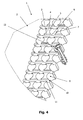
Fig. 4 is a further partial perspective view of the rack, wherein a part of the rack is shown in a sectional view with respect to line A-A ofFig. 3 ; and -
Fig. 5 shows a sectional view of the rack with respect to line B-B ofFig. 3 , wherein a screw is accommodated in one bore of the rack. - In the following the same reference numerals will be used to denote the same or similar structures in the drawings.
-
Fig. 1 shows a perspective view of an embodiment of arack 1 in the form of a tray that is configured to hold surgical screws for sterilization or cleaning purposes. Therack 1 comprises abody 2 in the form of a solid plate in which a plurality ofbores 7 is provided. Thebody 2 has anupper surface 4 bearing (e.g., printed or engraved) information and a lower surface. During surgery the right surgical screw has to be chosen for the right surgical purpose, and the information on theupper surface 4 may thus be indicative of at least one of a type, length and diameter of the screw in close association with the screw accommodated in therack 1. - The
rack 1 comprises sidewalls with openings that permit an easy access of a cleaning or sterilization medium to the surgical screws accommodated in thebody 2 in a hanging fashion. Therack 1 is intended to be placed together with the surgical screws accommodated therein in a chamber of a cleaning or sterilization device. Any fluid medium known in the art (such as hot water vapor) may be used for cleaning or sterilization purposes. -
Fig. 2 shows a partial top view of thebody 2 of therack 1 ofFig. 1 , wherein onesurgical screw 12 is accommodated in one of thebores 7 of therack 1. Eachbore 7 is surrounded by twosupport elements 3 which are arranged on opposite sides of thebore 7. It is also possible that three, four ormore support elements 3 were provided perbore 7. - As shown in
Fig. 3 , thesupport elements 3 protrude from a first level within the body 2 (i.e., below theupper surface 4 but above the lower surface thereof). Theupper surface 4 of the body (which in the present embodiment coincides with the upper surface of the support element 3) defines a second level which is above the first level. The screw head of thesurgical screw 12 is supported in therack 1 only at the second level defined by thesupport elements 3. The first level is defined by a bottom 11 of multipleparallel grooves 10 provided in theupper surface 4 of thebody 2. Eachgroove 10 is arranged between two rows ofbores 7 andsupport elements 3, as shown inFigs. 2 and3 . - The height of each
support element 3 is defined as the distance between the first level and the second level. Everysupport element 3 can have the same height (and its upper surface therewith the same distance to the bottom 11 of the groove 10). Asidewall 5 of thesupport element 3 forms the sidewall of theadjacent groove 10. - Two openings or
open spaces 6 are defined between the twosupport elements 3 that surround each bore 7 for enabling a fluid communication between theupper surface 4 of thebody 2 and thebore 7. As will be appreciated, the fluid communication is maintained even when thesurgical screw 12 is inserted with its shaft into thebore 7 and the screw head abuts thesupport elements 3. - The two
spaces 6 are arranged on opposite sides of thebore 7. Eachspace 6 stretches in a vertical direction from the first level to the second level. Hence, the height of each of thesupport elements 3 equals the height of each of thespaces 6. The cross-section of eachspace 6 is substantially rectangular and limited by the surroundingsupport elements 3 and the bottom 11 of the groove 10 (and the screw head). However, the cross-section of eachspace 6 can also be triangular or circular (or have any other shape) as long as a fluid medium can pass through thespace 6. - In general, each
support element 3 has a width which is defined between twosidewalls 5 of the support element 3 (each directed toward the respectiveopposite groove 10, as best shown inFig. 3 ) and a length which is defined in a direction parallel to theadjacent groove 10. As shown inFig. 2 , the width of eachsupport element 3 is slightly smaller than the diameter of an adjacent bore 7 (which gives rise to thespaces 6 upon milling thegrooves 10 into the body 2). - Each
support element 3 extends in a circumferential direction over approximately 135 degrees of a circumference of anindividual bore 7. The remaining circumference of the bore 7 (of approximately 90 degrees) is occupied by the twospaces 6 defined between thesupport elements 3, shared equally. When the circumference of eachsupport element 3 with respect to thebore 7 is reduced, the circumference of eachspace 6 is increased, and vice versa. Thus, when the width of thesupport element 3 becomes smaller, the width of eachspace 6 defined between thesupport elements 3 increases. -
Several bores 7 andsupport elements 3 arranged in a straight line define onerow 8, wherein eachrow 8 can have in principle also any other shape as long as thebores 7 are distanced from each other such that a fluid medium can easily access thescrews 12 accommodated in thebores 7.Several rows 8 are arranged side by side in theupper surface 4 of thebody 2. In the present embodiment, therows 8 ofbores 7 andsupport elements 3 are parallel to each other. - As stated above,
several grooves 10 are arranged between theparallel rows 8 ofbores 7 andsupport elements 3, wherein eachrow 8 is situated between twogrooves 10. Thebores 7 and thesupport elements 3 of onerow 8 are arranged in the same order as thebores 7 and thesupport elements 3 of anadjacent row 8 such that eachsupport element 3 or eachbore 3 faces anadjacent support element 3 or anadjacent bore 3 on the other side of thecommon groove 10. - The width of each
groove 11 arranged between tworows 8 ofbores 7 andsupport elements 3 is approximately half of the diameter of a bore 7 (or more). The central axes of thegrooves 10 are substantially perpendicular to the central axes of thebores 7. Eachbore 7 is in fluid communication with each of the twogrooves 10 which surround thebore 7 via thespaces 6 such that a fluid medium for cleaning or sterilization purposes is enabled to access thescrew 12 accommodated in thebore 7 from both sides via thegrooves 10. - Each
bore 7 is arranged between twosupport elements 3 such that the upper surfaces of thesupport elements 3 define a support portion to support thescrew 12 at or near the circumference of thebore 7, more particularly at the edges between theupper surfaces 4 of thesupport elements 3 and the sidewalls of thebore 7, as best shown inFigs. 4 and5 . Thus, thescrew 12, in particular the screw head of thescrew 12, is supported only at these edges. Thereby, the contact portion between thescrew 12 and each of the twosupport elements 3 is reduced to a curved line or a circular arc segment, which in turn increases the accessibility of thescrew 12 by a cleaning or sterilization medium. - Each
bore 7 is associated with twospaces 6 which are arranged on opposite sides relative to a central axis of thebore 7 and open into theadjacent grooves 10. Anadjacent bore 7 which is separated from thebore 7 by thecommon groove 10 also comprises twosuch spaces 6. These spaces of both bores are arranged in one straight line in a direction which is perpendicular to thegroove 10. Thus, a fluid medium for cleaning or sterilizing thescrews 12 accommodated in thebores 7 can pass therack 1 not only in longitudinal direction along thegrooves 10 but also in a transverse direction perpendicularly to thegrooves 10 through thespaces 6. - As best shown in
Fig. 5 , the diameter of the shaft of thescrew 12 is smaller than the diameter of thebore 7 of therack 1. The diameter of the screw head is larger than the diameter of thebore 7 so that screw can be supported at the second level by thesupport elements 3 surrounding thebore 7. The only contact portion between thescrew 12 and therack 1 is between thesupport elements 3 and the screw head. Thescrew 12 can thus be arranged in a hanging fashion such that the central axis of thescrew 12 is concentric to the central axis of the bore 7 (seeFig. 5 ). - The height of the
bore 7 is typically at least half of the length of thescrew 12 accommodated in thebore 7. Thebore 7 can have cylindrical sidewalls, or the sidewalls can have a concave or convex shape as long as the distance between the sidewalls of thebore 7 and thescrew 12 is sufficient to allow the fluid medium to access the screw for cleaning or sterilization purposes. - As also shown in
Figs. 3 and5 , the maximum diameter of the screw head is larger than the diameter of thebore 7 so that a part of the screw head overlaps with the two grooves which are arranged adjacent to thebore 7. Moreover, the screw head is located on the second level defined by theupper surface 4 of thesupport element 3. Hence, a user or removal instrument (such as tweezers) can easily grip thescrew 12 via thespaces 6 that are arranged on opposite sides of thebore 7. - As has come apparent from the description of an exemplary embodiment, the
rack 1 is adapted to accommodatescrews 12 which can be easily cleaned or sterilized due to the fact thatsupport elements 3 surrounding abore 7 defineopen spaces 6 therebetween for enabling fluid communication between therack surface 4 and thebore 7 so that a fluid medium can easily access the screw shaft and also the screw head. - Further, in one implementation the only contact area between the
screw 12 and therack 1 is the edge between thesupport elements 3 surrounding thebore 7 and the sidewall of thebore 7, so that the fluid medium can access essentially thewhole screw 12. A further advantage of the present disclosure is that due to thespaces 6 and the exposed screw head thescrew 12 can easily be inserted and picked up by a user or a removal instrument. - While the present disclosure has been described with respect to particular embodiments, those skilled in the art will recognize that the present disclosure is not limited to the specific embodiments described and illustrated therein. It is to be understood that the disclosure is only illustrative. Accordingly, it is intended that the invention be limited only to the scope of the claims attached thereto.
Claims (15)
- A rack (1) for holding at least one surgical screw (12) so as to be accessible by a fluid medium, wherein the at least one surgical screw (12) has a screw head and a screw shaft, the rack comprising:- a body (2) having a surface, wherein in the surface at least one bore (7) is provided that is configured to at least partly accommodate the screw shaft; and- at least two support elements (3) surrounding the bore (7), wherein the support elements (3) protrude from a first level defined on or in the body (2) and are configured to support the screw head on a second level above the first level, wherein the support elements (3) are spaced apart from each other to define spaces (6) therebetween that enable a fluid communication between the surface and the bore (7).
- The rack of claim 1, wherein the spaces (6) stretch in a vertical direction from the first level to the second level.
- The rack of claim 1 or 2, wherein the spaces (6) are arranged on opposite sides of the bore (7).
- The rack of any of the preceding claims, wherein each support element (3) extends over at most 170° of a circumference of the bore (7).
- The rack of any of the preceding claims, wherein several bores (7) and support elements (3) are arranged in a row (8).
- The rack of claim 5, wherein one common support element (3) is arranged between two bores (7).
- The rack of claim 5 or 6, wherein the row (8) has a linear shape.
- The rack of any of claims 6 to 7, wherein the row (8) of bores (7) and support elements (3) is arranged between two grooves (10), wherein the spaces (6) enable a fluid communication between the grooves (10) and bore (7).
- The rack of claim 8, wherein the row (8) of bores (7) and support elements (3) and the grooves (10) are parallel to each other.
- The rack of claim 8 or 9, wherein each groove (10) has a bottom (11) that defines the first level.
- The rack of any of claims 6 to 10, wherein multiple parallel rows (8) of bores (7) and support elements (3) are provided.
- A system comprising the rack (1) of any one of the preceding claims and one or more surgical screws (12) accommodated in the rack (1).
- The system of claim 12, wherein only the screw head of the surgical screw (12) is in contact with the body (2) of the rack (1).
- The system of claim 12 or 13, wherein a contact portion between the screw head accommodated in the rack (1) and each support element (3) surrounding the bore (7) is a curved line.
- The system of any of claims 12 to 14, wherein the distance between the first level and the second level is at least half the length of the surgical screw (12).
Priority Applications (2)
| Application Number | Priority Date | Filing Date | Title |
|---|---|---|---|
| EP11009096.6A EP2594219B1 (en) | 2011-11-16 | 2011-11-16 | Surgical screw rack |
| US13/673,149 US9107502B2 (en) | 2011-11-16 | 2012-11-09 | Surgical screw rack |
Applications Claiming Priority (1)
| Application Number | Priority Date | Filing Date | Title |
|---|---|---|---|
| EP11009096.6A EP2594219B1 (en) | 2011-11-16 | 2011-11-16 | Surgical screw rack |
Publications (2)
| Publication Number | Publication Date |
|---|---|
| EP2594219A1 true EP2594219A1 (en) | 2013-05-22 |
| EP2594219B1 EP2594219B1 (en) | 2016-01-13 |
Family
ID=45440018
Family Applications (1)
| Application Number | Title | Priority Date | Filing Date |
|---|---|---|---|
| EP11009096.6A Active EP2594219B1 (en) | 2011-11-16 | 2011-11-16 | Surgical screw rack |
Country Status (2)
| Country | Link |
|---|---|
| US (1) | US9107502B2 (en) |
| EP (1) | EP2594219B1 (en) |
Families Citing this family (7)
| Publication number | Priority date | Publication date | Assignee | Title |
|---|---|---|---|---|
| EP3062728B1 (en) * | 2013-11-01 | 2021-12-08 | Smith & Nephew, Inc. | Medical implant delivery system and method and an implant having a detachable marking section |
| US10471586B2 (en) | 2016-06-25 | 2019-11-12 | Channing Dewitt Wright | Apparatus, method, and system for hardware mapping and management |
| US10512517B2 (en) | 2016-07-08 | 2019-12-24 | Viant As&O Holdings, Llc | Modular screw caddy system with descriptive labels |
| US10028798B1 (en) | 2017-01-25 | 2018-07-24 | DePuy Synthes Products, Inc. | Single-use disposable sterile kit |
| US10470835B2 (en) * | 2017-01-25 | 2019-11-12 | DePuy Synthes Products, Inc. | Single use disposable sterile kit |
| CN109363759B (en) * | 2018-08-14 | 2019-11-22 | 乐清市钜派企业管理咨询有限公司 | Method for preparing orthopedic implants |
| US12036049B1 (en) * | 2023-02-10 | 2024-07-16 | DePuy Synthes Products, Inc. | Storage system with trays for long medical implants |
Citations (4)
| Publication number | Priority date | Publication date | Assignee | Title |
|---|---|---|---|---|
| DE20318732U1 (en) * | 2003-12-04 | 2004-02-26 | Richard Martin Medizintechnik Gmbh | Box for accommodation of surgical implants, comprising several rows of insertion areas for specifically designed screw holding elements |
| WO2006136291A1 (en) * | 2005-06-22 | 2006-12-28 | Aesculap Ag & Co. Kg | Surgical screw container |
| DE202007007409U1 (en) | 2007-05-16 | 2008-09-25 | Kögel GmbH | Sterilisatorenschraubenaufnahme |
| US20110108446A1 (en) * | 2009-11-09 | 2011-05-12 | Bettenhausen Cary A | Universal surgical fastener sterilization caddy |
Family Cites Families (18)
| Publication number | Priority date | Publication date | Assignee | Title |
|---|---|---|---|---|
| US4955476A (en) * | 1986-12-25 | 1990-09-11 | Matsushita Electric Industrial Co., Ltd. | Fastener carrier for the support of screw members |
| US4722440A (en) * | 1987-03-23 | 1988-02-02 | Chrysler Motors Corporation | Tray for transporting internal combustion engine pistons |
| USD335434S (en) | 1990-07-13 | 1993-05-11 | Santomi Shoji Co., Ltd. | Screw holding belt |
| JP2917621B2 (en) * | 1991-11-08 | 1999-07-12 | 松下電器産業株式会社 | Electrolytic capacitor packaging equipment |
| DE4303501A1 (en) * | 1993-02-06 | 1994-08-11 | Hans Schwartz | Holding device |
| USD356479S (en) | 1993-07-08 | 1995-03-21 | Chen Ho T | Screw holding belt |
| US6019225A (en) * | 1998-10-26 | 2000-02-01 | Matrix Technologies Corp. | Pipette tip rack with array of interconnected sleeves |
| US6286678B1 (en) * | 1999-03-05 | 2001-09-11 | Rainin Instruments Co., Inc. | Refill pack for pipette tip racks and improved pipette tip support plate for use in such packs and racks |
| US6474481B1 (en) * | 2001-06-08 | 2002-11-05 | Yung-Yuan Liu | Flexible tool storage device |
| AU2002953567A0 (en) * | 2002-12-24 | 2003-01-16 | Nielsen, John Peter | Surgical screw dispenser |
| DE10301690B3 (en) * | 2003-01-17 | 2004-09-09 | Stryker Leibinger Gmbh & Co. Kg | System and device for holding bone screws |
| WO2004082745A1 (en) * | 2003-02-24 | 2004-09-30 | Becton Dickinson France | Plate for holding a group of syringe body objects |
| DE102007015154A1 (en) * | 2007-03-22 | 2008-09-25 | Aesculap Ag & Co. Kg | Holding device for an implant |
| DE202007007407U1 (en) | 2007-05-21 | 2007-10-18 | Glinka, Gerhard | Panels, preferably as house facade panels |
| US8585743B2 (en) * | 2008-09-15 | 2013-11-19 | Biomet C.V. | Low profile screw and washer system for bone plating |
| DE202009002639U1 (en) * | 2009-02-26 | 2009-05-07 | Medartis Ag | Carrier and holder for surgical items |
| JP2013505071A (en) * | 2009-09-18 | 2013-02-14 | デピュイ・プロダクツ・インコーポレイテッド | Disposable orthopedic kits and components |
| IES20100693A2 (en) * | 2009-10-29 | 2011-06-08 | Gate Dental Services Ltd | A dental bur storage device |
-
2011
- 2011-11-16 EP EP11009096.6A patent/EP2594219B1/en active Active
-
2012
- 2012-11-09 US US13/673,149 patent/US9107502B2/en active Active
Patent Citations (4)
| Publication number | Priority date | Publication date | Assignee | Title |
|---|---|---|---|---|
| DE20318732U1 (en) * | 2003-12-04 | 2004-02-26 | Richard Martin Medizintechnik Gmbh | Box for accommodation of surgical implants, comprising several rows of insertion areas for specifically designed screw holding elements |
| WO2006136291A1 (en) * | 2005-06-22 | 2006-12-28 | Aesculap Ag & Co. Kg | Surgical screw container |
| DE202007007409U1 (en) | 2007-05-16 | 2008-09-25 | Kögel GmbH | Sterilisatorenschraubenaufnahme |
| US20110108446A1 (en) * | 2009-11-09 | 2011-05-12 | Bettenhausen Cary A | Universal surgical fastener sterilization caddy |
Also Published As
| Publication number | Publication date |
|---|---|
| US20130119001A1 (en) | 2013-05-16 |
| US9107502B2 (en) | 2015-08-18 |
| EP2594219B1 (en) | 2016-01-13 |
Similar Documents
| Publication | Publication Date | Title |
|---|---|---|
| US9107502B2 (en) | Surgical screw rack | |
| ES2606506T3 (en) | Surgical apparatus | |
| US7748529B2 (en) | Surgical instrument case | |
| US8821556B2 (en) | Support and mounting for surgical objects | |
| US10512517B2 (en) | Modular screw caddy system with descriptive labels | |
| US8162138B2 (en) | Universal surgical fastener sterilization caddy | |
| US5490975A (en) | Sterilization and storage container tray | |
| US20140069841A1 (en) | Modular Instrument Tray | |
| US10376329B2 (en) | Medical device tray and method of forming the medical device tray | |
| US10500025B2 (en) | Medical device tray and method of forming the medical device tray | |
| US6098802A (en) | Deep well rack assembly for pipette tips and the like | |
| EP1857057A3 (en) | Surgical stapling instruments including a cartridge having multiple staple sizes | |
| US9457180B2 (en) | Electrode clamp | |
| US11324577B2 (en) | Dental tool holder | |
| JP6743146B2 (en) | Occipital-cervical fixation for occipital-cervical fixation and system for occipital-cervical fixation | |
| US11090402B2 (en) | Flexible divider for filter baskets | |
| US10039630B2 (en) | Implant container and implant container system | |
| US20080206112A1 (en) | Modular test tube holder | |
| US20130074450A1 (en) | Apparatus and method for securing medical instruments | |
| US7350643B2 (en) | System and device for keeping bone screws ready | |
| EP3042626B1 (en) | Medical device tray and method of forming the medical device tray | |
| TW202027860A (en) | Modular reagent plate and reagent vessel kit | |
| KR101437153B1 (en) | Forceps for gripping medical screws | |
| US20060118445A1 (en) | Surgical instrument container assembly with snap fit handle assembly | |
| EP3363474A1 (en) | Modular tray support for autoclave |
Legal Events
| Date | Code | Title | Description |
|---|---|---|---|
| PUAI | Public reference made under article 153(3) epc to a published international application that has entered the european phase |
Free format text: ORIGINAL CODE: 0009012 |
|
| 17P | Request for examination filed |
Effective date: 20120622 |
|
| AK | Designated contracting states |
Kind code of ref document: A1 Designated state(s): AL AT BE BG CH CY CZ DE DK EE ES FI FR GB GR HR HU IE IS IT LI LT LU LV MC MK MT NL NO PL PT RO RS SE SI SK SM TR |
|
| AX | Request for extension of the european patent |
Extension state: BA ME |
|
| 17Q | First examination report despatched |
Effective date: 20130829 |
|
| REG | Reference to a national code |
Ref country code: DE Ref legal event code: R079 Ref document number: 602011022561 Country of ref document: DE Free format text: PREVIOUS MAIN CLASS: A61B0019000000 Ipc: A61L0002260000 |
|
| GRAP | Despatch of communication of intention to grant a patent |
Free format text: ORIGINAL CODE: EPIDOSNIGR1 |
|
| RIC1 | Information provided on ipc code assigned before grant |
Ipc: A61B 19/00 20060101ALI20150601BHEP Ipc: B65D 25/10 20060101ALI20150601BHEP Ipc: A61J 1/00 20060101ALI20150601BHEP Ipc: A61L 2/26 20060101AFI20150601BHEP |
|
| INTG | Intention to grant announced |
Effective date: 20150706 |
|
| RAP1 | Party data changed (applicant data changed or rights of an application transferred) |
Owner name: STRYKER TRAUMA GMBH |
|
| GRAS | Grant fee paid |
Free format text: ORIGINAL CODE: EPIDOSNIGR3 |
|
| GRAA | (expected) grant |
Free format text: ORIGINAL CODE: 0009210 |
|
| AK | Designated contracting states |
Kind code of ref document: B1 Designated state(s): AL AT BE BG CH CY CZ DE DK EE ES FI FR GB GR HR HU IE IS IT LI LT LU LV MC MK MT NL NO PL PT RO RS SE SI SK SM TR |
|
| REG | Reference to a national code |
Ref country code: GB Ref legal event code: FG4D |
|
| REG | Reference to a national code |
Ref country code: CH Ref legal event code: NV Representative=s name: SCHMAUDER AND PARTNER AG PATENT- UND MARKENANW, CH Ref country code: CH Ref legal event code: EP |
|
| REG | Reference to a national code |
Ref country code: IE Ref legal event code: FG4D |
|
| REG | Reference to a national code |
Ref country code: AT Ref legal event code: REF Ref document number: 770062 Country of ref document: AT Kind code of ref document: T Effective date: 20160215 |
|
| RAP2 | Party data changed (patent owner data changed or rights of a patent transferred) |
Owner name: STRYKER EUROPEAN HOLDINGS I, LLC |
|
| REG | Reference to a national code |
Ref country code: DE Ref legal event code: R096 Ref document number: 602011022561 Country of ref document: DE |
|
| REG | Reference to a national code |
Ref country code: LT Ref legal event code: MG4D |
|
| REG | Reference to a national code |
Ref country code: NL Ref legal event code: MP Effective date: 20160113 |
|
| REG | Reference to a national code |
Ref country code: AT Ref legal event code: MK05 Ref document number: 770062 Country of ref document: AT Kind code of ref document: T Effective date: 20160113 |
|
| PG25 | Lapsed in a contracting state [announced via postgrant information from national office to epo] |
Ref country code: NL Free format text: LAPSE BECAUSE OF FAILURE TO SUBMIT A TRANSLATION OF THE DESCRIPTION OR TO PAY THE FEE WITHIN THE PRESCRIBED TIME-LIMIT Effective date: 20160113 |
|
| PG25 | Lapsed in a contracting state [announced via postgrant information from national office to epo] |
Ref country code: GR Free format text: LAPSE BECAUSE OF FAILURE TO SUBMIT A TRANSLATION OF THE DESCRIPTION OR TO PAY THE FEE WITHIN THE PRESCRIBED TIME-LIMIT Effective date: 20160414 Ref country code: FI Free format text: LAPSE BECAUSE OF FAILURE TO SUBMIT A TRANSLATION OF THE DESCRIPTION OR TO PAY THE FEE WITHIN THE PRESCRIBED TIME-LIMIT Effective date: 20160113 Ref country code: ES Free format text: LAPSE BECAUSE OF FAILURE TO SUBMIT A TRANSLATION OF THE DESCRIPTION OR TO PAY THE FEE WITHIN THE PRESCRIBED TIME-LIMIT Effective date: 20160113 Ref country code: HR Free format text: LAPSE BECAUSE OF FAILURE TO SUBMIT A TRANSLATION OF THE DESCRIPTION OR TO PAY THE FEE WITHIN THE PRESCRIBED TIME-LIMIT Effective date: 20160113 Ref country code: NO Free format text: LAPSE BECAUSE OF FAILURE TO SUBMIT A TRANSLATION OF THE DESCRIPTION OR TO PAY THE FEE WITHIN THE PRESCRIBED TIME-LIMIT Effective date: 20160413 Ref country code: IT Free format text: LAPSE BECAUSE OF FAILURE TO SUBMIT A TRANSLATION OF THE DESCRIPTION OR TO PAY THE FEE WITHIN THE PRESCRIBED TIME-LIMIT Effective date: 20160113 |
|
| REG | Reference to a national code |
Ref country code: DE Ref legal event code: R081 Ref document number: 602011022561 Country of ref document: DE Owner name: STRYKER EUROPEAN OPERATIONS HOLDINGS LLC, KALA, US Free format text: FORMER OWNER: STRYKER TRAUMA GMBH, 24232 SCHOENKIRCHEN, DE Ref country code: DE Ref legal event code: R081 Ref document number: 602011022561 Country of ref document: DE Owner name: STRYKER EUROPEAN OPERATIONS HOLDINGS LLC, KALA, US Free format text: FORMER OWNER: STRYKER EUROPEAN HOLDINGS VI, LLC (N.D. GES. D. STAATES DELAWARE), KALAMAZOO, MICH., US Ref country code: DE Ref legal event code: R082 Ref document number: 602011022561 Country of ref document: DE Representative=s name: WUESTHOFF & WUESTHOFF, PATENTANWAELTE PARTG MB, DE Ref country code: DE Ref legal event code: R081 Ref document number: 602011022561 Country of ref document: DE Owner name: STRYKER EUROPEAN HOLDINGS I, LLC (N.D. GES. D., US Free format text: FORMER OWNER: STRYKER EUROPEAN HOLDINGS VI, LLC (N.D. GES. D. STAATES DELAWARE), KALAMAZOO, MICH., US Ref country code: DE Ref legal event code: R081 Ref document number: 602011022561 Country of ref document: DE Owner name: STRYKER EUROPEAN HOLDINGS I, LLC (N.D. GES. D., US Free format text: FORMER OWNER: STRYKER TRAUMA GMBH, 24232 SCHOENKIRCHEN, DE |
|
| PG25 | Lapsed in a contracting state [announced via postgrant information from national office to epo] |
Ref country code: SE Free format text: LAPSE BECAUSE OF FAILURE TO SUBMIT A TRANSLATION OF THE DESCRIPTION OR TO PAY THE FEE WITHIN THE PRESCRIBED TIME-LIMIT Effective date: 20160113 Ref country code: RS Free format text: LAPSE BECAUSE OF FAILURE TO SUBMIT A TRANSLATION OF THE DESCRIPTION OR TO PAY THE FEE WITHIN THE PRESCRIBED TIME-LIMIT Effective date: 20160113 Ref country code: PT Free format text: LAPSE BECAUSE OF FAILURE TO SUBMIT A TRANSLATION OF THE DESCRIPTION OR TO PAY THE FEE WITHIN THE PRESCRIBED TIME-LIMIT Effective date: 20160513 Ref country code: LV Free format text: LAPSE BECAUSE OF FAILURE TO SUBMIT A TRANSLATION OF THE DESCRIPTION OR TO PAY THE FEE WITHIN THE PRESCRIBED TIME-LIMIT Effective date: 20160113 Ref country code: LT Free format text: LAPSE BECAUSE OF FAILURE TO SUBMIT A TRANSLATION OF THE DESCRIPTION OR TO PAY THE FEE WITHIN THE PRESCRIBED TIME-LIMIT Effective date: 20160113 Ref country code: IS Free format text: LAPSE BECAUSE OF FAILURE TO SUBMIT A TRANSLATION OF THE DESCRIPTION OR TO PAY THE FEE WITHIN THE PRESCRIBED TIME-LIMIT Effective date: 20160513 Ref country code: AT Free format text: LAPSE BECAUSE OF FAILURE TO SUBMIT A TRANSLATION OF THE DESCRIPTION OR TO PAY THE FEE WITHIN THE PRESCRIBED TIME-LIMIT Effective date: 20160113 Ref country code: PL Free format text: LAPSE BECAUSE OF FAILURE TO SUBMIT A TRANSLATION OF THE DESCRIPTION OR TO PAY THE FEE WITHIN THE PRESCRIBED TIME-LIMIT Effective date: 20160113 |
|
| REG | Reference to a national code |
Ref country code: DE Ref legal event code: R097 Ref document number: 602011022561 Country of ref document: DE Ref country code: FR Ref legal event code: PLFP Year of fee payment: 6 |
|
| PG25 | Lapsed in a contracting state [announced via postgrant information from national office to epo] |
Ref country code: EE Free format text: LAPSE BECAUSE OF FAILURE TO SUBMIT A TRANSLATION OF THE DESCRIPTION OR TO PAY THE FEE WITHIN THE PRESCRIBED TIME-LIMIT Effective date: 20160113 Ref country code: DK Free format text: LAPSE BECAUSE OF FAILURE TO SUBMIT A TRANSLATION OF THE DESCRIPTION OR TO PAY THE FEE WITHIN THE PRESCRIBED TIME-LIMIT Effective date: 20160113 |
|
| PLBE | No opposition filed within time limit |
Free format text: ORIGINAL CODE: 0009261 |
|
| STAA | Information on the status of an ep patent application or granted ep patent |
Free format text: STATUS: NO OPPOSITION FILED WITHIN TIME LIMIT |
|
| PG25 | Lapsed in a contracting state [announced via postgrant information from national office to epo] |
Ref country code: SM Free format text: LAPSE BECAUSE OF FAILURE TO SUBMIT A TRANSLATION OF THE DESCRIPTION OR TO PAY THE FEE WITHIN THE PRESCRIBED TIME-LIMIT Effective date: 20160113 Ref country code: RO Free format text: LAPSE BECAUSE OF FAILURE TO SUBMIT A TRANSLATION OF THE DESCRIPTION OR TO PAY THE FEE WITHIN THE PRESCRIBED TIME-LIMIT Effective date: 20160113 Ref country code: CZ Free format text: LAPSE BECAUSE OF FAILURE TO SUBMIT A TRANSLATION OF THE DESCRIPTION OR TO PAY THE FEE WITHIN THE PRESCRIBED TIME-LIMIT Effective date: 20160113 Ref country code: SK Free format text: LAPSE BECAUSE OF FAILURE TO SUBMIT A TRANSLATION OF THE DESCRIPTION OR TO PAY THE FEE WITHIN THE PRESCRIBED TIME-LIMIT Effective date: 20160113 |
|
| 26N | No opposition filed |
Effective date: 20161014 |
|
| PG25 | Lapsed in a contracting state [announced via postgrant information from national office to epo] |
Ref country code: BE Free format text: LAPSE BECAUSE OF FAILURE TO SUBMIT A TRANSLATION OF THE DESCRIPTION OR TO PAY THE FEE WITHIN THE PRESCRIBED TIME-LIMIT Effective date: 20160113 |
|
| PG25 | Lapsed in a contracting state [announced via postgrant information from national office to epo] |
Ref country code: BG Free format text: LAPSE BECAUSE OF FAILURE TO SUBMIT A TRANSLATION OF THE DESCRIPTION OR TO PAY THE FEE WITHIN THE PRESCRIBED TIME-LIMIT Effective date: 20160413 Ref country code: SI Free format text: LAPSE BECAUSE OF FAILURE TO SUBMIT A TRANSLATION OF THE DESCRIPTION OR TO PAY THE FEE WITHIN THE PRESCRIBED TIME-LIMIT Effective date: 20160113 |
|
| REG | Reference to a national code |
Ref country code: GB Ref legal event code: 732E Free format text: REGISTERED BETWEEN 20170331 AND 20170405 |
|
| REG | Reference to a national code |
Ref country code: GB Ref legal event code: 732E Free format text: REGISTERED BETWEEN 20170406 AND 20170412 |
|
| REG | Reference to a national code |
Ref country code: IE Ref legal event code: MM4A |
|
| PG25 | Lapsed in a contracting state [announced via postgrant information from national office to epo] |
Ref country code: LU Free format text: LAPSE BECAUSE OF NON-PAYMENT OF DUE FEES Effective date: 20161130 |
|
| REG | Reference to a national code |
Ref country code: FR Ref legal event code: PLFP Year of fee payment: 7 |
|
| PG25 | Lapsed in a contracting state [announced via postgrant information from national office to epo] |
Ref country code: IE Free format text: LAPSE BECAUSE OF NON-PAYMENT OF DUE FEES Effective date: 20161116 |
|
| PG25 | Lapsed in a contracting state [announced via postgrant information from national office to epo] |
Ref country code: HU Free format text: LAPSE BECAUSE OF FAILURE TO SUBMIT A TRANSLATION OF THE DESCRIPTION OR TO PAY THE FEE WITHIN THE PRESCRIBED TIME-LIMIT; INVALID AB INITIO Effective date: 20111116 Ref country code: CY Free format text: LAPSE BECAUSE OF FAILURE TO SUBMIT A TRANSLATION OF THE DESCRIPTION OR TO PAY THE FEE WITHIN THE PRESCRIBED TIME-LIMIT Effective date: 20160113 |
|
| PG25 | Lapsed in a contracting state [announced via postgrant information from national office to epo] |
Ref country code: TR Free format text: LAPSE BECAUSE OF FAILURE TO SUBMIT A TRANSLATION OF THE DESCRIPTION OR TO PAY THE FEE WITHIN THE PRESCRIBED TIME-LIMIT Effective date: 20160113 Ref country code: MC Free format text: LAPSE BECAUSE OF FAILURE TO SUBMIT A TRANSLATION OF THE DESCRIPTION OR TO PAY THE FEE WITHIN THE PRESCRIBED TIME-LIMIT Effective date: 20160113 Ref country code: MK Free format text: LAPSE BECAUSE OF FAILURE TO SUBMIT A TRANSLATION OF THE DESCRIPTION OR TO PAY THE FEE WITHIN THE PRESCRIBED TIME-LIMIT Effective date: 20160113 |
|
| PG25 | Lapsed in a contracting state [announced via postgrant information from national office to epo] |
Ref country code: MT Free format text: LAPSE BECAUSE OF NON-PAYMENT OF DUE FEES Effective date: 20161116 |
|
| REG | Reference to a national code |
Ref country code: FR Ref legal event code: PLFP Year of fee payment: 8 |
|
| PG25 | Lapsed in a contracting state [announced via postgrant information from national office to epo] |
Ref country code: AL Free format text: LAPSE BECAUSE OF FAILURE TO SUBMIT A TRANSLATION OF THE DESCRIPTION OR TO PAY THE FEE WITHIN THE PRESCRIBED TIME-LIMIT Effective date: 20160113 |
|
| REG | Reference to a national code |
Ref country code: CH Ref legal event code: PK Free format text: BERICHTIGUNGEN |
|
| RIC2 | Information provided on ipc code assigned after grant |
Ipc: A61B 19/00 20060101ALI20150601BHEP Ipc: A61L 2/26 20060101AFI20150601BHEP Ipc: A61J 1/00 20060101ALI20150601BHEP Ipc: B65D 25/10 20060101ALI20150601BHEP |
|
| REG | Reference to a national code |
Ref country code: DE Ref legal event code: R082 Ref document number: 602011022561 Country of ref document: DE Representative=s name: WUESTHOFF & WUESTHOFF, PATENTANWAELTE PARTG MB, DE Ref country code: DE Ref legal event code: R081 Ref document number: 602011022561 Country of ref document: DE Owner name: STRYKER EUROPEAN OPERATIONS HOLDINGS LLC, KALA, US Free format text: FORMER OWNER: STRYKER EUROPEAN HOLDINGS I, LLC (N.D. GES. D. STAATES DELAWARE), KALAMAZOO, MICH., US |
|
| REG | Reference to a national code |
Ref country code: GB Ref legal event code: 732E Free format text: REGISTERED BETWEEN 20210408 AND 20210414 |
|
| P01 | Opt-out of the competence of the unified patent court (upc) registered |
Effective date: 20230522 |
|
| PGFP | Annual fee paid to national office [announced via postgrant information from national office to epo] |
Ref country code: GB Payment date: 20250925 Year of fee payment: 15 |
|
| PGFP | Annual fee paid to national office [announced via postgrant information from national office to epo] |
Ref country code: FR Payment date: 20250908 Year of fee payment: 15 |
|
| REG | Reference to a national code |
Ref country code: CH Ref legal event code: U11 Free format text: ST27 STATUS EVENT CODE: U-0-0-U10-U11 (AS PROVIDED BY THE NATIONAL OFFICE) Effective date: 20251201 |
|
| PGFP | Annual fee paid to national office [announced via postgrant information from national office to epo] |
Ref country code: DE Payment date: 20250923 Year of fee payment: 15 |
|
| PGFP | Annual fee paid to national office [announced via postgrant information from national office to epo] |
Ref country code: CH Payment date: 20251201 Year of fee payment: 15 |