EP2593786B1 - Dampening apparatus and method for single piston pump used in determining the thermal stability of fluids - Google Patents
Dampening apparatus and method for single piston pump used in determining the thermal stability of fluids Download PDFInfo
- Publication number
- EP2593786B1 EP2593786B1 EP11807318.8A EP11807318A EP2593786B1 EP 2593786 B1 EP2593786 B1 EP 2593786B1 EP 11807318 A EP11807318 A EP 11807318A EP 2593786 B1 EP2593786 B1 EP 2593786B1
- Authority
- EP
- European Patent Office
- Prior art keywords
- test sample
- sample
- test
- heater tube
- pump
- Prior art date
- Legal status (The legal status is an assumption and is not a legal conclusion. Google has not performed a legal analysis and makes no representation as to the accuracy of the status listed.)
- Active
Links
Images








Classifications
-
- G—PHYSICS
- G01—MEASURING; TESTING
- G01N—INVESTIGATING OR ANALYSING MATERIALS BY DETERMINING THEIR CHEMICAL OR PHYSICAL PROPERTIES
- G01N33/00—Investigating or analysing materials by specific methods not covered by groups G01N1/00 - G01N31/00
- G01N33/26—Oils; Viscous liquids; Paints; Inks
- G01N33/28—Oils, i.e. hydrocarbon liquids
- G01N33/2805—Oils, i.e. hydrocarbon liquids investigating the resistance to heat or oxidation
Definitions
- This invention relates to methods and devices for measuring the thermal characteristics of fluids. Specifically, this invention relates to the dampening apparatus and method for a single piston pump used in a system to measure the thermal oxidation tendencies of fuels for liquid hydrocarbon-burning engines.
- This early Hundere patent was designed to test the deposition characteristics of jet fuels by determining (1) deposits on the surface of a heater tube at an elevated temperature and (2) differential pressure across a filter due to collection of particulate matter. To this day, according to ASTM D3241, the two critical measurements are still (1) the deposits collected on a heater tube and (2) differential pressure across the filter due to the collection of particulate matter on the filter.
- ASTM D3241 450 mL of fuel flows across an aluminum heater tube at a specified rate, during a 2.5 hour test period at an elevated temperature.
- JFTOT® 1 instruments are approved for use in the ASTM D3241 -09 Standard.
- the "09” refers to the current revision of the ASTM D3241 Standard.
- the determination of the amount of deposits formed on the heater tube at an elevated temperature is an important part of the test.
- the current ASTM D3241 test method requires a visual comparison between the heater tube deposits and known color standard. However, this involves a subjective evaluation with the human eye. To take away the subjectivity of a person, an electronic video tube deposit rater was developed.
- the recorded information and the heater tube are preserved to show the batch of fuel was properly tested.
- the information that was recorded when testing a batch of fuel is maintained separately from the heater tube itself. This can cause a problem if one or the other gets misplaced or lost. Inaccurate information and/or conclusions occur if the wrong set of data is associated with the wrong heater tube.
- US 4,448,692 relates to a solvent delivery device for liquid chromatography and, more particularly, to such a device which delivers solvent to a liquid chromatography column using a plunger pump.
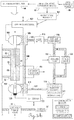
- Fig. 1 is a schematic block diagram of a thermal oxidation stability tester referred to generally by the reference numeral 20.
- the thermal oxidation stability tester 20 has an embedded computer 21 with a touch screen 23 for user interface. While many different types of programs could be run, in the preferred embodiment, Applicant is running C++ in the embedded computer 21.
- the touch screen 23 displays all of the information from the thermal oxidation stability tester 20 that needs to be conveyed to the user. The user communicates back and forth with the embedded computer 21 through the touch screen 23. If a batch of fuel is to be tested, a test sample is put in the sample delivery system 25.
- the embedded computer 21 operates a sample aeration control 31 for a period of time to make sure the sample is fully aerated. The aeration of the sample takes place at the beginning of the test.
- the embedded computer 21 turns on a sample flow control 27, which is a pump used to deliver the sample throughout the thermal oxidation stability tester 20.
- sample pressure control 29 maintains a fixed pressure throughout the system. It is important to maintain pressure in the system to prevent boiling of the test sample when at elevated temperatures. In the present thermal oxidation stability tester 20, the sample is maintained at approximately 3447.4 kPa (500 psi) when undergoing the thermal oxidation stability test.
- the embedded computer 21 controls parameters affecting the intelligent heater tube 33.
- the test data is recorded to the intelligent heater tube 33 via intelligent heater tube writer 35 from the embedded computer 21.
- Critical test parameters are recorded on a memory device (as described subsequently) on an end of the intelligent heater tube 33 via the intelligent heater tube writer 35. The rating of the deposit formed on the intelligent heater tube 33 will be recorded on the memory device at a later time.
- the intelligent heater tube 33 is heated by tube heater control 37.
- the tube heater control 37 causes current to flow through the intelligent heater tube 33, which causes it to heat up to the temperature set point.
- bus-bar coolant control 39 provides coolant upper and lower bus-bars holding each end of the intelligent heater tube 33. This results in the center section of the intelligent heater tube 33 reaching the prescribed temperature while the ends of the intelligent heater tube 33 are maintained at a lower temperature. This is accomplished by flowing coolant via the bus-bar coolant control 39 across the ends of the intelligent heater tube 33.
- test parameters such as the dimension of the heater tube, pressure of the test sample or flow rate are fixed by ASTM D3241 However, the control of these parameters are the focus of this invention.
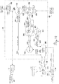
- a schematic flow diagram is shown connecting the mechanical and electrical functions.
- the embedded computer 21 and the touch screen 23 provide electrical signals as indicated by the arrows.
- a test sample is contained in the sample container 41.
- an aeration pump 43 is turned ON.
- the aeration pump 43 pumps air through a dryer 45 where the air is dehumidified to remove moisture.
- a percent relative humidify sensor 47 determines the humidity level of the pumped air and provides that information to the embedded computer 21. Assuming the percent humidity of the pumped air is sufficiently low, the test procedure will continue pumping air through the flow meter 49 and aeration check valve 50 into the sample container 41.
- flow meter 49 should record approximately 0.09m 3 /hr (1.5 liters of air per minute). Since the flow meter 49 runs for approximately six minutes, the aeration pump 43 will sparge approximately 0.009m 3 (nine liters) of air into the test sample. This is sufficient time to saturate the test sample with dry air.
- a sample temperature measurement 51 is taken and provided to the embedded computer 21.
- the sample temperature measurement 51 is to ensure that the test sample is between 15°-32°C. If the test sample is outside of this temperature range, results can be impacted. Therefore, if the test sample is outside this temperature range, the embedded computer 21 would not let the test start.
- the sample drive pump 53 is a single piston HPLC pump, also known as a metering pump. With every stroke of the piston, a fixed volume of the sample is delivered. The speed of the sample drive pump 53 is controlled so that it pumps 0.00018m 3 /hr (3 mL/min) of the test sample.
- the sample drive pump 53 is configured for fast refill which minimizes the need for manual pump priming. Pulsations, associated with pumps of this design are minimized with the use of a pulse dampener and a coil tubing on the outlet side as will be subsequently described.
- an auto pump priming valve 55 is opened, a sample vent valve 54 is closed and the aeration pump 43 is turned ON by the embedded computer 21.
- the auto pump priming valve 55 opens and remains open while a combination of sample and air is discharged into waste container 57.
- the aeration pump 43 provides positive pressure in the sample container 41 to force test sample from the sample container 41 to the sample drive pump 53.
- the sample vent valve 54 closes to prevent venting of the air pressure to atmosphere to maintain a pressure of (13.8 to 20.7 kPa (2 to 3 psi).
- a sample vent check valve 56 across the sample vent valve 54 opens at 34.5 kPa (5 psi) to prevent the pressure in the sample container 41 from exceeding 34.5 kPa (5 psi).
- the pre-filter 61 removes solid particles in the test sample that could affect the test.
- the pre-filter 61 is a very fine filter, normally in the order of 0.45 micron in size.
- the purpose of the pre-filter 61 is to make sure particles do not get into the test filter as will be described.
- the pre-filter 61 is replaced before every test.
- the test sample flows through an inlet 63 into the cylindrical heater tube test section 65.
- Outlet 67 while illustrated as two separate outlets, is actually a single outlet at the upper end of the cylindrical heater tube test section 65.
- Extending through the cylindrical heater tube test section 65 is the intelligent heater tube 69, sealed at each end with ceramic bushings and an o-ring (not shown). While the test sample flows through the cylindrical heater tube test section 65 via inlet 63 and outlet 67 and around the intelligent heater tube 69, the housing of the cylindrical heater tube test section 65 is electrically isolated from the intelligent heater tube 69. Only the test sample comes in contact with the center section of the intelligent heater tuber 69. Inside of the intelligent heater tube 69 is a thermocouple 71 that sends a signal back to the embedded computer 21 as to the temperature of the center section of the intelligent heater tube 69.
- the intelligent heater tube 69 heats up the test sample inside of the cylindrical heater tube test section 65 to the test parameter set point. Heating of the test sample may result in degradation of the test sample, or cause solid particles to form. The solid particles may deposit on the center section of the intelligent heater tube 69, and/or may collect on the differential pressure filter 73.
- the pressure drop across the differential pressure filter 73 is measured by differential pressure sensor 75. Pressure across the differential pressure filter 73 is continuously monitored by the embedded computer 21 through the differential pressure sensor 75.
- the test sample must remain as a liquid. At typical testing temperatures of 250°C to 350°C, many hydrocarbon fuels will transition to the vapor phase at ambient pressures.
- the back pressure regulator 79 maintains approximately 3447.4 kPa (500 psi) pressure in the system. This system pressure is monitored by the system pressure sensor 81, which reports information to the embedded computer 21.
- normal flow of a test sample is through differential pressure filter 73 and through the back pressure regulator 79. From the back pressure regulator 79, the test sample flows through sample flowmeter 83 to waste container 57.
- the sample flow meter 83 accurately measures the flow rate of the test sample during the test.
- the sample flow meter 83 provides sample flow rate information to the embedded computer 21.
- a system/safety vent valve 85 is connected into the system and controlled via the embedded computer 21.
- the system/safety vent valve 85 acts to relieve excess system pressure in the case of power loss, improperly functioning system components or other system failures.
- the system pressure sensor 81 sends a signal to the embedded computer 21 , triggering the system/safety vent valve 85 to open and relieve excess pressure.
- the system/safety vent valve 85 opens to vent pressure from the system.
- the system/safety vent valve 85 is normally set to the open position requiring a program command to through the embedded computer 21 to close the system/safety vent valve 85. Therefore, if power is lost, the system/safety vent valve 85 automatically opens.
- the flush air pump 87 turns ON and flushes air through flush check valve 89 to remove the test sample from the system.
- the flush air pump 87 pushes most of the test sample out of the system via the system/safety vent valve 85 into the waste container 57.
- the system may not operate properly if there are air pockets or air bubbles in the system.
- the solenoid operated differential pressure plus vent valve 91 and the differential pressure minus vent valve 93 are opened so that the test section 65, differential pressure filter 73, differential pressure sensor 75 and connecting differential pressure line are, flushed with test sample, and vented to remove any air pockets that may be present.
- the position of the differential pressure vent valves 91 and 93 ensure there is no air in the differential pressure lines.
- waste container 57 If the waste container 57 is properly installed in position, a signal will be fed back to the embedded computer 21 indicating the waste container 57 is correctly connected. This also applies for the sample container 41 which sends a signal to the embedded computer 21 when it is properly connected. The system will not operate unless both the waste container 57 and the sample container 41 are properly positioned.
- the center portion of the intelligent heater tube 69 is heated to the test parameter set point by flowing current through the intelligent heater tube 69.
- Instrument power supplied for current generation and all other instrument controls is provided through local available power 95. Depending on local power availability, local available power 95 may vary drastically. In some areas it is 50 cycles/sec. and in other areas it is 60 cycles/sec. The voltage range may vary from a high of 240 Volts down to 80 Volts or less.
- a universal AC/DC converter 97 takes the local available power 95 and converts it to 48 Volts DC. With the universal AC/DC converter 97, a good, reliable, constant 48 Volts DC is generated. The 48 Volts DC from the universal AC/DC converter 97 is distributed throughout the system to components that need power through the DC power distribution 99. If some of the components need a voltage level other than 48 Volts DC, the DC power distribution 99 will change the 48 Volts DC to the required voltage level.
- the 48 Volts from the universal AC/DC converter 97 is converted to 115 Volts AC through 48 Volt DC/115 Volts AC inverter 101. While taking any local available power 95 , running it through a universal AC/DC converter 97 and then changing the power back to 115 Volts AC through DC/AC inverter 101, a stable power supply is created. While this design uses 48 Volts DC, it is possible to use a universal AC/DC converter and DC/AC inverter that operates with other voltages such as 12 Volts DC, 24 Volts DC or 230 Volts AC. From the 48 Volts DC/115 Volts AC inverter 101, power is supplied to the heater tube module 103.
- the heater tube module 103 then supplies current that flows through the intelligent heater tube 69 via upper clamp 105 and lower clamp 107.
- the heater tube module 103 is controlled by the embedded computer 21 so that during a normal test, the thermocouple 71 inside of the intelligent heater tube 69 will indicate when the intelligent heater tube 69 has reached the desired temperature.
- a coolant flows through an upper bus-bar 109 and lower bus-bar 111.
- the coolant inside the upper bus-bar 109 and lower bus-bar 111 cools the upper clamp 105 and lower clamp 107 which are attached to the ends of the intelligent heater tube 69.
- the preferred cooling solution is a mixture of approximately 50% water and 50% antifreeze (ethylene glycol). As the coolant flows through electrically non-conductive conduit 135 to the coolant container 115, the flow is measured by flow meter 113.
- a cooling pump 117 pumps the coolant solution into a radiator assembly 119. Inside of the radiator assembly 119, the coolant is maintained at room temperature. The radiator fan 121 helps remove heat from the coolant by drawing air through the radiator assembly 119. From the radiator assembly 119, the coolant flows through electrically non-conductive conduit 131 into the lower bus-bar 111 then through electrically non-conductive conduit 108 to upper bus-bar 109 prior to returning via the flow meter 113.
- the flow meter 113 is adjustable so that it can ensure a flow of approximately 0.045m 3 /hr (10 gal./hr).
- the check valve 123 helps ensure the cooling system will not be over pressurized. Check valve 123 will open at around 48.3 kPa (7 psi), but normally 20.7-27.6 kPa (3-4 psi) will be developed when running the coolant through the entire system.
- a heater tube short detector 110 monitors a short condition. If a short is detected, the embedded computer 21 is notified and the test is stopped.
- the intelligent heater tube 69 there is a memory device 125 to which information concerning the test can be recorded by IHT writer 127 as will be discussed in more detail. While a test is being run on a test sample, the IHT writer 127 will record information into the memory device 125. At the end of the test, all electronic information will be recorded onto the memory device 125 of the intelligent heater tube 69, except for the manual tube deposit rating. To record this information, the intelligent heater tube 69 will have to be moved to another location to record the deposit rating either (a) visually or (b) through a Video Tube Deposit Rater. At that time, a second IHT writer will write onto the memory device 125.
- the Video Tube Deposit Rater may be built into the system or may be a standalone unit.
- the intelligent heater tube 69 is approximately 17.1cm (6-3/4") long. The ends are approximately 0.48cm (3/16") in diameter, but the center portion that is heated is approximately 0.3cm (1/8") in diameter. Due to very low electrical resistance of aluminum, approximately 200 to 250 amps of current flows through the intelligent heater tube 69. Both the voltage and the current through the intelligent heater tube 69 is monitored by the embedded computer 21, but also the temperature of the center section of the intelligent heater tube 69 is monitored by the thermocouple 71 which is also connected to the embedded computer 21. The objective is to have the center section of the intelligent heater tube 69 at the required temperature. To generate that type of stable temperature, a stable source of power is provided through the universal AC/DC converter 97 and then the 48 VDC/115 VAC inverter 101. By using such a stable source of power, the temperature on the center section of the heater tube 69 can be controlled within a couple of degrees of the required temperature even if the local available power is unstable.
- FIG. 3 a pictorial representation of the coolant flow during a test is illustrated. Like numbers will be used to designate similar components as previously described.
- a pictorial illustration of the heater tube test section 129 is illustrated on the lower left portion of Fig.3 .
- Coolant from the radiator assembly 119 is provided to the lower bus-bar 111 via conduit 131 then to upper bus-bar 109 via conduit 108. From the upper bus-bar 109, the coolant flows via conduit 133 to flow meter 113. From flow meter 113, the coolant flows through conduit 135 to the coolant container 115.
- the cooling pump 117 receives the coolant through conduit 137 from the coolant container 115 and pumps the coolant into radiator assembly 119. If the pressure from the cooling pump 117 is too high, check valve 123 will allow some of the coolant to recirculate around the cooling pump 117.
- Fig. 3 is intended to be a pictorial representation illustrating how the coolant flows during a test.
- Fig. 4 is a pictorial representation of the aeration system for the test sample. Similar numbers will be used to designate like components as previously described.
- An aeration pump 43 pumps air through conduit 139 to a dryer 45.
- the dryer 45 removes moisture from the air to prevent the moisture from contaminating the test sample during aeration. From the dryer 45, the dried air will flow through conduit 141 to humidity sensor 47. If the percent relative humidity of the dried air blowing through conduit 141 exceeds a predetermined amount of 20% relative humidity, the system will shut down. While different types of dryers 45 can be used, it was found that Dry-Rite silica gel desiccant is an effective material for producing the desired relative humidity.
- the dried air flows through conduit 143 to flow meter 49, which measures the air flow through conduit 143 and air supply conduit 145.
- the dried air flows through aeration check valve 50 and conduit 146 sample container arm mounting clamp 147 and sample container arm 149 to aeration conduit 151 located inside of sample container 41.
- a glass frit 153 connects to aeration conduit 151 to cause the dried air to sparge through the test sample in sample container 41.
- Fig.5 a pictorial illustration of the flow of the test sample in connection with Figs.2 and 2A is shown in a schematic flow diagram.
- the test sample is contained in sample container 41, which is connected via sample container arm 149 to the sample container arm mounting clamp 147. Vapors given off by the test sample are discharged through a vent 157, normally through a vent hood to atmosphere.
- the sample drive pump 53 draws some of the test sample out of the sample container 41.
- the sample drive pump 53 is a single stroke HPLC pump connected to a pulse dampener.
- the pulse dampener 159 may be configured a number of ways, the pulse dampener 159 in the preferred configuration has a diaphragm with a semi-compressible fluid on one side of the diaphragm. This fluid is more compressible than the test sample thereby reducing pressure changes on the test sample flow discharged from the sample drive pump 53.
- the sample drive pump 53 is connected to auto pump priming valve 55.
- the closed auto pump priming valve 55 opens until all of the air contained in the pump and the lines are discharged into the waste container 57.
- a manual priming valve 161 is also provided.
- the aeration pump 43 is turned ON to provide a slight pressure in the sample container 41 of about 13.8 to 20.7 kPa (2 to 3 psi).
- the sample vent valve 54 closes to prevent this pressure escaping to atmosphere. This pressure will help push the fluid sample from the sample container 41 to the inlet of the sample drive pump 53.
- the 34.5 kPa (5 psi) check valve 56 prevents the pressure in the sample container exceeding 34.5 kPa (5 psi).
- coil 163 also provides further dampening in addition to the pulse dampener 159.
- Check valve 59 ensures there is no back flow of the sample fuel to the sample drive pump 53. However, at the end of a test, flush check valve 89 receives air from flush air pump 87 to flush the test sample out of the system.
- the sample fuel will flow through check valve 59 and through a pre-filter 61 removing most solid particles.
- the test sample flows into the heater tube test section 129 and then through the differential pressure filter 73.
- Each side of the differential pressure filter 73 connects to the differential pressure sensor 75.
- the back pressure regulator 79 Also connected to the differential pressure filter 73 is the back pressure regulator 79.
- the pressure on the system is continuously monitored through the system pressure transducer 81. If for any reason pressure on the system needs to be released, system/safety vent valve 85 is de-energized and the pressurized test sample is vented through the four-way cross connection 165 to the waste container 57.
- the differential pressure plus vent valve 91 and the differential pressure minus vent valve 93 are opened to vent any pressurized fluid through the four-way cross connection 165 to the waste container 57.
- differential pressure bypass valve 77 will open to relieve the pressure.
- the sample flow meter 83 measures the flow rate of test sample from the back pressure regulator 79 before being discharged through the waste container arm 167 and the waste container clamp 169 into the waste container 57.
- the waste container 57 is vented all the time through vent 171.
- IHT Intelligent Heater Tube
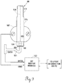
- the intelligent heater tube (IHT) 69 is shown in Figure 6 .
- the intelligent heater tube 69 is cylindrical in shape as described previously.
- the top 173 and bottom 175 are 0.48cm (3/16") in diameter.
- the test section 177 is 0.3cm (1/8") in diameter.
- Extending longitudinally along the center axis of the intelligent heater tube 69 is a center bore 179.
- the thermocouple 71 (previously described in conjunction with Fig.2A ) is located inside the center bore 179.
- At the end of the enlarged bottom 175 is a memory device 125.
- the memory device 125 is slightly smaller in diameter than the heater tube bottom 175.
- an EEPROM 181 is located inside of the memory device 125.
- the EEPROM 181 only has a data signal and a ground signal.
- the ground signal connects to ground stick 183 and the data signal connects to data plate 185.
- the ground stick 183 fits inside of the center bore 179 of the intelligent heater tube 69.
- the EEPROM 181 is contained inside of insulated housing 187 of the memory device 125.
- the data plate 185 is on the end of the insulated housing 187 and is slightly smaller in diameter than the insulated housing 187. The only two connections to the memory device 125 are through the ground stick 183 and the data plate 185.
- the EEPROM 181 has a total of six solder connections 189, only two of them are connected to either the ground stick 183 or data plate 185.
- the data plate 185 is made from a material that will not tarnish easily such as phosphorous bronze or beryllium copper.
- the entire memory device 125 is resistant to degradation from jet fuel or related materials. To ensure there is no accidental electrical connection, the data plate 185 is slightly smaller in diameter than the insulated housing 187 of memory device 125, which in turn is slightly smaller in diameter than the enlarged bottom 175 of the intelligent heater tube 69.
- FIG. 9 a pictorial example of how to connect to the memory device 125 of the intelligent heater tube 69 when running a test of a sample fuel is shown.
- the intelligent heater tube 69 is held in position by lower clamp 107.
- the ground stick 183 of the EEPROM 181 is contained inside of center bore 179 of the enlarged bottom 175.
- an IHT writer 127 as shown in connection with Fig. 2A is used.
- the IHT writer 127 has a data line that connects to a spring-loaded contact 191 that pushes against, and makes electrical contact with, the data plate 185.
- the other side of the IHT writer 127 connects to ground via lower clamp 107, intelligent heater tube 69 and ground stick 183.
- the output from the IHT writer 127 can either go directly to the JFTOT®, to a video tube deposit rater, or to a personal computer.
- One IHT writer 127 will be located inside of a jet fuel thermal oxidation stability tester (JFTOT®).
- Another IHT writer 127 will be used to record the deposit information as collected on the test section 177 of the intelligent heater tube 69 as is recorded either (a) manually from a visual inspection or (b) with the Video Tube Deposit Rater.
- the IHT writer 127 when installed on the test apparatus only communicates with the embedded computer 21 shown in Fig. 2 . After the test has been run, the only information lacking on the memory device 125 is recording the heater tube deposit rating. This will be recorded either from a manual inspection of the intelligent heater tube 69 or from a video tube deposit rater, either of which will require a separate IHT writer module 127.
- the IHT writer module 127 uses 5 Volts DC as its normal power.
- a USB port 193 is used to connect the IHT writer 127.
- USB port 193 has four wires for a positive supply voltage VCC, a negative signal voltage D-, a positive signal voltage D+ and a ground GND.
- the IHT writer 127 has a RS 232 port with four wires being used to transmit data TXD, received data RXD, ground GND, and positive supply voltage VCC. From the IHT writer 127, one wire is for data and one wire is for ground which are used when connecting to the memory device 125 containing the EEPROM 181.
- the USB port 193 and the RS 232 port 195 supplies data through the IHT writer 127 to the memory device 125.
- a UART TTL level 197 that converts the data to the appropriate form to communicate to EEPROM 181.
- the abbreviation UART stands for "Universal Acrosynchronous Receiver/Transmitter”.
- TTL is an abbreviation for "Transistor-Transistor Logic”.
- the JFTOT® 230 Mark III can be configured with or without a Video Tube Deposit Rater, to work with the intelligent heater tube 69 having the memory device 125 as shown in the combination of Figs. 10 and 11 .
- the embedded computer 21 connects through RS 232 port 195 to the second intelligent heater tube writer 201, which is similar to IHT writer 127. If the test system does not have a video tube deposit rater module, then IHT writer 203 may be used to write to the memory device 125 of the intelligent heater tube 69. In this manner, the IHT writer 203 can be used to manually input the data into the memory device 125.
- RS 232 port 196 connects the embedded computer 21 to the Video Tube Deposit Rater (VTDR) module 205.
- VTDR Video Tube Deposit Rater
- the eject/close device 207 By pressing the eject/close device 207, the door of the VTDR module 205 will open and the intelligent heater tube 69 may be inserted.
- the start button 209 By pushing the start button 209, deposits collected on the intelligent heater tube 69 during the test are rated. The rating is automatically recorded onto the EEPROM chip 181 (not shown in Fig. 11 ) contained in the memory device 125.
- the image data from the VTDR module 205 may be retrieved by VTDR LAN connection 211.
- IHT writer modules are used in the full system. One writer module is used while the heater tube is in the run position. The other writer module is used when the deposit rating is being recorded.
- eject/close device 207 is pressed to open the door to allow removal of the intelligent heater tube 69. Now, all of the information recorded from that test is contained with the intelligent heater tube 69. Since most users keep the recorded data and the heater tube, this allows both to be archived together.
- the sample drive pump as shown in Figs. 2 and 5 is a high-pressure, low-volume pump.
- Prior versions of the JFTOT that have been available on the market use a dual-piston pump to prevent wide swings in pump outlet sample flow during strokes of the piston.
- one of the drawbacks of using a dual-piston pump occurs after long periods of non-use where remnants of a test sample can dry and leave a sticky residue on the check valve.
- Sticky check valves can make it difficult to prime the pump because once the check valves for one of the pistons becomes operational it has a tendency to allow sample to flow through the now flowing valves and bypass the other stuck check valves. This will require the need to disassemble the piston and clean the check valves.
- the sample drive pump 53 of the present invention is a single piston pump, but with numerous ways to prevent fluctuations in output flow between strokes of the single piston.
- the sample drive pump 53 is operated by a control module 300 as shown in the schematic of Fig. 12 .
- the control module 300 receives its power from DC power distribution 99 shown in Fig. 2A .
- the control module 300 is connected to the embedded computer 21.
- the embedded computer 21 is operated by touch screen 23.
- Control module 300 communicates with the embedded computer 21 through communications line 302. Enable line 304 allows the embedded computer 21 to turn the sample drive pump 53 ON or OFF through control module 300.
- the embedded computer 21 has an ON/OFF signal 306 to the DC power distribution 99, which ON/OFF signal 306 will turn power ON or OFF to the sample drive pump 53 via control module 300. Therefore, if the embedded computer 21 determines that any part of the JFTOT is not operating properly, including the program, power thereto can be shut OFF. Turning power OFF to the sample drive pump 53 is a safety mechanism in case something is not operating properly.
- DC power distribution 99 From the DC power distribution 99, the +48 Volts being supplied through the control module 300 is used to provide motor power 310 to motor 308. Also, DC power distribution 99 provides +21 Volts to operate the electronics contained in the control module 300.
- the motor 308 is a stepper motor that will turn incrementally pursuant to pulses received from the control module 300 in the form of motor power 310. By incrementally providing power to motor 308, the motor 308 will incrementally turn, which incrementally turns drive belt 312.
- the drive belt 312 has teeth therein that mates with a tooth gear (not shown) so there is no slippage between the drive belt 312 and the tooth gear.
- a tooth gear is provided on both ends of the drive belt 312 as will be explained in detail subsequently.
- Eccentric cam 314 is an off-centered cam with an eccentric shape that rotates in a circle about center as pictorially illustrated.
- shaft 322 is pushed during 270° of rotation of the eccentric cam 314, and retracted during only 90° of rotation of eccentric cam 314.
- a spring (not shown in Fig. 12 ) continually urges the shaft 322 against the eccentric cam 314.
- the eccentric cam 314 and shaft 322 are held together by mechanical assembly 324.
- slotted disc 316 also turns at the same rotational speed or a rotational speed directly proportional thereto.
- an opto-interrupter 318 can sense when the slot 317 passes adjacent thereto and sends a pulse signal 320 to the control module 300.
- the pulse signal 320 lets the control module 300 know that the motor 308 is running, eccentric cam 314 turning and at what speeds.
- Check valve 334 is also a gravity-operated ball-and-seat check valve. While many different types of check valves can be used, a gravity-operated check valve with a large seat area helps prevent sticking after periods of non-use. During non-use, remnants of a test sample may have remained therein, dried up and left a sticky coating, so using a check valve with a large ball and seat provides a larger area to help any pressure across the valve to unstick the valve.
- Pressure inside of the pump head 328 of the sample drive pump 53 is anywhere from 3447.4 to 17236.9 kPa (500 to 2,500 psi), depending upon the flow rate. In normal operations over 6894.8 kPa (1,000 psi) will be seen in the pump head 328. Any gas or air contained inside of pump head 328 will cause the sample drive pump 53 to not operate properly so it is important to remove any air during priming.
- piston 326 extends into the pump head 328 during three-fourths (or 270°), of each rotation of motor 328 and eccentric cam 314.
- the speed of the motor can be increased or decreased by changing the pulses that are being feed thereto from the control module 300.
- the lag time between pumping cycles is decreased.
- the motor can be made to operate four times faster when retracting piston 326.
- Pulse dampener 159 receives the pressurized test sample from pressure conduit 342 connected to outlet check valve 334.
- the pulse dampener 159 has a diaphragm therein (not shown) which has a semi-compressible fluid on one side thereof and the pressurized test sample on the other side.
- the semi-compressible fluid is alcohol. Therefore, as each pulsation of pressurized test sample is received from check valve 334, pulse dampener 159 acts to smooth out the sample flow fluctuations or pulses.
- a restriction is added downstream of the pulse dampener 159 in the form of a 3447.4 kPa (500 psi) coil 163.
- the 3447.4 kPa (500 psi) coil 163 will cause a pressure drop of 3447.4 kPa (500 psi).
- the coil 163 has a 0.16cm (1/16") outside diameter and is made from stainless steel tubing. The inside diameter is 0.01778cm (7/1,000 of an inch). In the coil 163, there are approximately four loops about 10.16cm (4") in diameter.
- the inlet pressure to coil 163 will be approximately 6894.8 kPa (1,000 psi) and the outlet pressure approximately 3447.4 kPa (500 psi) with a flow rate of 0.00018m 3 /hr (3 ml./min.) there through.
- the pressurized test sample from coil 163 feeds through check valve 59 (see Fig.2 ) into the entire system for testing to determine the thermal stability of the fluid under test. While different configurations of quantities of pulse dampeners, sizes of pressure coils and check valve sizes can be used, the components described in this embodiment provide the same flow pulsations as the dual-piston pump used in the previous versions of the JFTOT.
- pulse dampener 159 has a pressure transducer 336 that provides a pressure signal 338 back to the control module 300.
- the control module 300 can monitor the outlet pressure by the pulse dampener 159 to make sure the pressure is not too high. If the pressure gets too high, the control module 300 can stop motor 308 and stop the test. The control module 300 can further send a signal to notify the embedded computer 21 that the pump has stopped. The embedded computer 21 then turns OFF the remaining parts of the JFTOT. Feedback through pressure transducer 336 is an additional safety feature to ensure that everything is operating properly.
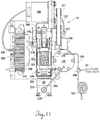
- Figs. 13 and 14 the mechanical layout of the sample drive pump 53 is shown. Everything for the sample drive pump 53 is mounted on base 344. Base 344 has bracket 345 supporting the control module 300 thereon. Heat sink 348 helps dissipate any heat generated by the electronics contained in the control module 300.
- the mechanical assembly 324 is attached to base 344 by legs 347 that are secured to the base 344 and rest against vibration dampeners 346. While the leg 347 can be made in many different ways, legs 347 are formed integrally with the mechanical assembly 324.
- belt drive 312 begins to turn.
- Drive sprocket 311 has teeth therein to match the tooth portion of the belt drive 312.
- cam sprocket 313 has sprockets therein to match the belt drive 312. This ensures the belt drive 312 will not slip on either the drive sprocket 311 or cam sprocket 313.
- eccentric cam 314 As the eccentric cam 314 turns, it pushes against shaft 322, which is urged against eccentric cam 314 by spring 323. As the shaft 322 is pushed forward, it pushes piston 326 forward into pump head 328. Likewise, as shaft 322 retracts, piston 326 will retract from pump head 328.
- the pressurized sample flows through flow conduit 350 and T-connection 340 into 3447.4 kPa (500 psi) coil 163.
- the coil 163 provides about a 3447.4 kPa (500 psi) pressure drop therein which acts to further dampen the flow fluctuations of the test sample as it comes out of the pulse dampener 159.
- Fig. 15(a) shows the overall variation in a normal 0.00018m 3 /hr (3.0 mL/min) flow versus time.
- Fig. 15(b) shows an expanded flow variation versus time with the lower part of the chart cut off. The variation in flow of the test sample when compared to the overall flow of the test sample is insignificant.
- a single piston pump can be used as the sample drive pump 53 when testing for thermal stability of fluids, particularly jet fuel.
Landscapes
- Chemical & Material Sciences (AREA)
- Health & Medical Sciences (AREA)
- Engineering & Computer Science (AREA)
- Life Sciences & Earth Sciences (AREA)
- Medicinal Chemistry (AREA)
- Oil, Petroleum & Natural Gas (AREA)
- General Chemical & Material Sciences (AREA)
- Food Science & Technology (AREA)
- Chemical Kinetics & Catalysis (AREA)
- Physics & Mathematics (AREA)
- Analytical Chemistry (AREA)
- Biochemistry (AREA)
- General Health & Medical Sciences (AREA)
- General Physics & Mathematics (AREA)
- Immunology (AREA)
- Pathology (AREA)
- Sampling And Sample Adjustment (AREA)
Description
- This invention relates to methods and devices for measuring the thermal characteristics of fluids. Specifically, this invention relates to the dampening apparatus and method for a single piston pump used in a system to measure the thermal oxidation tendencies of fuels for liquid hydrocarbon-burning engines.
- When engines were developed for use in jet aircraft, problems began to develop for jet fuel due to poor fuel thermal stability. At higher temperatures, the jet fuels would oxidize and form deposits that would clog fuel nozzles and fuel filters. These deposits would also collect in the jet engine.
- While various tests were devised and used in the 1950s and 60s to rate the thermal oxidation characteristics of jet fuels prior to being used in jet aircraft, Alf Hundere developed the apparatus and method which became the standard in the industry. In 1970, AlfHundere filed what became
U.S. Patent No.3,670,561 , titled "Apparatus for Determining the Thermal Stability of Fluids". This patent was adopted in 1973 as ASTM D3241 Standard, entitled "Standard Test Method for Thermal Oxidation Stability of Aviation Turbine Fuels", also known as the "JFTOT® Procedure". This early Hundere patent was designed to test the deposition characteristics of jet fuels by determining (1) deposits on the surface of a heater tube at an elevated temperature and (2) differential pressure across a filter due to collection of particulate matter. To this day, according to ASTM D3241, the two critical measurements are still (1) the deposits collected on a heater tube and (2) differential pressure across the filter due to the collection of particulate matter on the filter. - According to ASTM D3241, 450 mL of fuel flows across an aluminum heater tube at a specified rate, during a 2.5 hour test period at an elevated temperature. Currently six different models of JFTOT®1 instruments are approved for use in the ASTM D3241 -09 Standard. The "09" refers to the current revision of the ASTM D3241 Standard.
- While over the years various improvements have been made in the apparatus to run the tests, the basic test remains the same. Improvements in the apparatus can be seen in
U.S. Patent Nos. 5,337,599 and5,101,658 . These patents disclose apparatus and methods for determining the thermal stability of fluids, particularly for testing the deposition characteristics of fuels. The current model being sold is the JFTOT 230 Mark III, which is described in further detail in the "Jet Fuel Thermal Oxidation Tester - User's Manual". The determination of the deposits that occur on the heater tube can be made visually by comparing to known color standards or can be made using a "Video Tube Deposit Rater" sold under the Alcor mark. - The determination of the amount of deposits formed on the heater tube at an elevated temperature is an important part of the test. The current ASTM D3241 test method requires a visual comparison between the heater tube deposits and known color standard. However, this involves a subjective evaluation with the human eye. To take away the subjectivity of a person, an electronic video tube deposit rater was developed.
- Also, there has been considerable discussion as to the polish or finish of the heater tube. (See
U.S. Patent No.7,093,481 and U.S. Patent Application Publication No.US 2002/083,760 .) The finish of the heater tube is very important in determining the amount of fuel deposits that will form thereon. Therefore, it is important that the quality of the finish on heater tubes made today be consistent with the finish of heater tubes made since 1973. - Once the thermal oxidation stability test has been performed on a batch of fuel, the recorded information and the heater tube are preserved to show the batch of fuel was properly tested. The information that was recorded when testing a batch of fuel is maintained separately from the heater tube itself. This can cause a problem if one or the other gets misplaced or lost. Inaccurate information and/or conclusions occur if the wrong set of data is associated with the wrong heater tube.
- In prior versions of the JFTOT, a low volume, high pressure pump has been used that has two pistons. A less expensive single piston pump caused too large of a variation in output pressure to be used, especially when pumping at such a low volume and high pressure.
-
US 4,448,692 relates to a solvent delivery device for liquid chromatography and, more particularly, to such a device which delivers solvent to a liquid chromatography column using a plunger pump. - The present invention is defined by the claims.
- It is an object of the present invention to provide an apparatus and method for testing thermal oxidation stability of fluids, particularly aviation fuels.
- It is another object of the present invention to provide an apparatus and method to measure the tendency of fuels to form deposits when in contact with heated surfaces.
- It is another object of the present invention to provide an apparatus and method for testing the thermal oxidation tendency of fuels utilizing a test sample to determine if solid particles will form in the fuel at an elevated temperature and pressure.
- It is another object of the present invention to provide an apparatus and method for determining thermal oxidation stability of a batch of aviation fuel by testing a sample at an elevated temperature and pressure to determine (1) deposits that form on a metal surface and (2) solid particles that form in the fuel.
- It is still another object of the present invention to provide dampening for a low volume, high pressure, single piston pump so that such a pump can be used when testing thermal oxidation stability of fluids, particularly aviation fuels.
-
-
Fig. 1 is a general block diagram of a thermal oxidation stability test apparatus illustrating flow and electrical controls. -
Figs. 2 and2A are a more detailed block diagram showing a thermal oxidation test apparatus used to perform ASTM D3241 Standard. -
Fig. 3 is a pictorial diagram of the coolant flow forFigs. 2 and2A . -
Fig. 4 is a pictorial diagram of the airflow inFigs. 2 and2A -
Fig. 5 is a pictorial diagram showing flow of the test sample inFigs. 2 and2A . -
Fig. 6 is a lengthwise view of an intelligent heater tube. -
Fig.7 is an exploded perspective end view of the intelligent heater tube ofFig.6 , showing the EEPROM in broken lines inside of a memory device on the intelligent heater tube. -
Fig. 8 is an elevated view of the 1-Wire EEPROM used in the memory device ofFig. 7 . -
Fig.9 is a pictorial illustration of how to record data on the memory device of an intelligent heater tube. -
Fig. 10 is a schematic diagram of the writer module used to write on a 1 -Wire EEPROM. -
Fig. 11 is a schematic diagram of a built-in Video Tube Deposit Rater for use with an intelligent heater tube. -
Fig. 12 is a schematic view illustrating use of a low volume, high pressure, single piston pump with sufficient dampening in a thermal oxidation stability tester. -
Fig. 13 is a perspective view of the actual pump schematically illustrated inFig. 12 . -
Fig. 14 is a top view of the actual pump schematically illustrated inFig. 12 . -
Figs. 15(a) and 15(b) are graphs showing variations in flow of the fluid under test. -
Fig. 1 is a schematic block diagram of a thermal oxidation stability tester referred to generally by thereference numeral 20. The thermaloxidation stability tester 20 has an embeddedcomputer 21 with atouch screen 23 for user interface. While many different types of programs could be run, in the preferred embodiment, Applicant is running C++ in the embeddedcomputer 21. Thetouch screen 23 displays all of the information from the thermaloxidation stability tester 20 that needs to be conveyed to the user. The user communicates back and forth with the embeddedcomputer 21 through thetouch screen 23. If a batch of fuel is to be tested, a test sample is put in thesample delivery system 25. - It is important to the test to make sure the test sample is oxygen saturated through aeration. Therefore, the embedded
computer 21 operates asample aeration control 31 for a period of time to make sure the sample is fully aerated. The aeration of the sample takes place at the beginning of the test. - The embedded
computer 21 turns on asample flow control 27, which is a pump used to deliver the sample throughout the thermaloxidation stability tester 20. Simultaneous with thesample flow control 27 pumping the test sample throughout the system,sample pressure control 29 maintains a fixed pressure throughout the system. It is important to maintain pressure in the system to prevent boiling of the test sample when at elevated temperatures. In the present thermaloxidation stability tester 20, the sample is maintained at approximately 3447.4 kPa (500 psi) when undergoing the thermal oxidation stability test. - Also, the embedded
computer 21 controls parameters affecting theintelligent heater tube 33. The test data is recorded to theintelligent heater tube 33 via intelligentheater tube writer 35 from the embeddedcomputer 21. Critical test parameters are recorded on a memory device (as described subsequently) on an end of theintelligent heater tube 33 via the intelligentheater tube writer 35. The rating of the deposit formed on theintelligent heater tube 33 will be recorded on the memory device at a later time. - In performing the thermal oxidation stability test on a test sample, the
intelligent heater tube 33 is heated bytube heater control 37. Thetube heater control 37 causes current to flow through theintelligent heater tube 33, which causes it to heat up to the temperature set point. - To prevent the hot
intelligent heater tube 33 from heating other parts of the thermaloxidation stability tester 20, bus-bar coolant control 39 provides coolant upper and lower bus-bars holding each end of theintelligent heater tube 33. This results in the center section of theintelligent heater tube 33 reaching the prescribed temperature while the ends of theintelligent heater tube 33 are maintained at a lower temperature. This is accomplished by flowing coolant via the bus-bar coolant control 39 across the ends of theintelligent heater tube 33. - The test parameters, such as the dimension of the heater tube, pressure of the test sample or flow rate are fixed by ASTM D3241 However, the control of these parameters are the focus of this invention.
- Referring now to
Figs. 2 and2A in combination, a schematic flow diagram is shown connecting the mechanical and electrical functions. The embeddedcomputer 21 and thetouch screen 23 provide electrical signals as indicated by the arrows. A test sample is contained in thesample container 41. To make sure the sample and thesample container 41 is fully aerated, anaeration pump 43 is turned ON. Theaeration pump 43 pumps air through adryer 45 where the air is dehumidified to remove moisture. From thedryer 45, a percentrelative humidify sensor 47 determines the humidity level of the pumped air and provides that information to the embeddedcomputer 21. Assuming the percent humidity of the pumped air is sufficiently low, the test procedure will continue pumping air through theflow meter 49 andaeration check valve 50 into thesample container 41. During aeration,flow meter 49 should record approximately 0.09m3/hr (1.5 liters of air per minute). Since theflow meter 49 runs for approximately six minutes, theaeration pump 43 will sparge approximately 0.009m3 (nine liters) of air into the test sample. This is sufficient time to saturate the test sample with dry air. - Within the
sample container 41, asample temperature measurement 51 is taken and provided to the embeddedcomputer 21. Thesample temperature measurement 51 is to ensure that the test sample is between 15°-32°C. If the test sample is outside of this temperature range, results can be impacted. Therefore, if the test sample is outside this temperature range, the embeddedcomputer 21 would not let the test start. - Once the test sample has been aerated and if all the other parameters are within tolerance, then the
sample drive pump 53 will turn ON. Thesample drive pump 53 is a single piston HPLC pump, also known as a metering pump. With every stroke of the piston, a fixed volume of the sample is delivered. The speed of thesample drive pump 53 is controlled so that it pumps 0.00018m3/hr (3 mL/min) of the test sample. Thesample drive pump 53 is configured for fast refill which minimizes the need for manual pump priming. Pulsations, associated with pumps of this design are minimized with the use of a pulse dampener and a coil tubing on the outlet side as will be subsequently described. - To get air out of the tubing between the
sample container 41 and thesample drive pump 53 at the start of the test, an autopump priming valve 55 is opened, asample vent valve 54 is closed and theaeration pump 43 is turned ON by the embeddedcomputer 21. The autopump priming valve 55 opens and remains open while a combination of sample and air is discharged intowaste container 57. At the same time theaeration pump 43 provides positive pressure in thesample container 41 to force test sample from thesample container 41 to thesample drive pump 53. Thesample vent valve 54 closes to prevent venting of the air pressure to atmosphere to maintain a pressure of (13.8 to 20.7 kPa (2 to 3 psi). A samplevent check valve 56 across thesample vent valve 54 opens at 34.5 kPa (5 psi) to prevent the pressure in thesample container 41 from exceeding 34.5 kPa (5 psi). Once thesample drive pump 53 starts pumping the test sample, autopump priming valve 55 will close and thesample vent valve 54 will open. Thereafter, thesample drive pump 53 will pump the test sample throughcheck valve 59 to theprefilter 61. Thecheck valve 59 prevents fluid from flowing backwards through thesample drive pump 53. Thecheck valve 59 operates at a pressure of approximately 34.5 kPa (5 psi). Thecheck valve 59 prevents siphoning when thesample drive pump 53 is not pumping. Also,check valve 59 prevents fluid from being pushed backwards into thesample drive pump 53. - The pre-filter 61 removes solid particles in the test sample that could affect the test. The pre-filter 61 is a very fine filter, normally in the order of 0.45 micron in size. The purpose of the pre-filter 61 is to make sure particles do not get into the test filter as will be described. The pre-filter 61 is replaced before every test.
- From the pre-filter 61 , the test sample flows through an
inlet 63 into the cylindrical heatertube test section 65.Outlet 67, while illustrated as two separate outlets, is actually a single outlet at the upper end of the cylindrical heatertube test section 65. Extending through the cylindrical heatertube test section 65 is theintelligent heater tube 69, sealed at each end with ceramic bushings and an o-ring (not shown). While the test sample flows through the cylindrical heatertube test section 65 viainlet 63 andoutlet 67 and around theintelligent heater tube 69, the housing of the cylindrical heatertube test section 65 is electrically isolated from theintelligent heater tube 69. Only the test sample comes in contact with the center section of theintelligent heater tuber 69. Inside of theintelligent heater tube 69 is athermocouple 71 that sends a signal back to the embeddedcomputer 21 as to the temperature of the center section of theintelligent heater tube 69. - Test sample flowing from the cylindrical heater
tube test section 65 flows through adifferential pressure filter 73, commonly called the "test filter". In a manner as will be explained in more detail, theintelligent heater tube 69 heats up the test sample inside of the cylindrical heatertube test section 65 to the test parameter set point. Heating of the test sample may result in degradation of the test sample, or cause solid particles to form. The solid particles may deposit on the center section of theintelligent heater tube 69, and/or may collect on thedifferential pressure filter 73. The pressure drop across thedifferential pressure filter 73 is measured bydifferential pressure sensor 75. Pressure across thedifferential pressure filter 73 is continuously monitored by the embeddedcomputer 21 through thedifferential pressure sensor 75. When the pressure across thedifferential pressure filter 73 exceeds a predefined differential of approximately 33.3 kPa to 37.3 kPa (250 mm to 280 mm of mercury), the differentialpressure bypass valve 77 opens to relieve the pressure. By test definition, exceeding a differential pressure of 3.3 kPa (25 mm Hg) results in failure of the test. - For this test to be performed, the test sample must remain as a liquid. At typical testing temperatures of 250°C to 350°C, many hydrocarbon fuels will transition to the vapor phase at ambient pressures. To keep the test sample in the liquid phase, the
back pressure regulator 79 maintains approximately 3447.4 kPa (500 psi) pressure in the system. This system pressure is monitored by thesystem pressure sensor 81, which reports information to the embeddedcomputer 21. During a test, normal flow of a test sample is throughdifferential pressure filter 73 and through theback pressure regulator 79. From theback pressure regulator 79, the test sample flows throughsample flowmeter 83 to wastecontainer 57. Thesample flow meter 83 accurately measures the flow rate of the test sample during the test. Thesample flow meter 83 provides sample flow rate information to the embeddedcomputer 21. - A system/
safety vent valve 85 is connected into the system and controlled via the embeddedcomputer 21. The system/safety vent valve 85 acts to relieve excess system pressure in the case of power loss, improperly functioning system components or other system failures. In the event of this occurrence, thesystem pressure sensor 81 sends a signal to the embeddedcomputer 21 , triggering the system/safety vent valve 85 to open and relieve excess pressure. Also, at the completion of a test, the system/safety vent valve 85 opens to vent pressure from the system. The system/safety vent valve 85 is normally set to the open position requiring a program command to through the embeddedcomputer 21 to close the system/safety vent valve 85. Therefore, if power is lost, the system/safety vent valve 85 automatically opens. - At the end of the test, after the system/
safety vent valve 85 is opened and system pressure is relieved, theflush air pump 87 turns ON and flushes air throughflush check valve 89 to remove the test sample from the system. Theflush air pump 87 pushes most of the test sample out of the system via the system/safety vent valve 85 into thewaste container 57. - The system may not operate properly if there are air pockets or air bubbles in the system. During a test, it is important to maintain an air-free system. Therefore, at the beginning of each test, the solenoid operated differential pressure plus vent
valve 91 and the differential pressure minus ventvalve 93 are opened so that thetest section 65,differential pressure filter 73,differential pressure sensor 75 and connecting differential pressure line are, flushed with test sample, and vented to remove any air pockets that may be present. During the beginning of each test, the position of the differentialpressure vent valves - If the
waste container 57 is properly installed in position, a signal will be fed back to the embeddedcomputer 21 indicating thewaste container 57 is correctly connected. This also applies for thesample container 41 which sends a signal to the embeddedcomputer 21 when it is properly connected. The system will not operate unless both thewaste container 57 and thesample container 41 are properly positioned. - The center portion of the
intelligent heater tube 69 is heated to the test parameter set point by flowing current through theintelligent heater tube 69. Instrument power supplied for current generation and all other instrument controls is provided through localavailable power 95. Depending on local power availability, localavailable power 95 may vary drastically. In some areas it is 50 cycles/sec. and in other areas it is 60 cycles/sec. The voltage range may vary from a high of 240 Volts down to 80 Volts or less. A universal AC/DC converter 97 takes the localavailable power 95 and converts it to 48 Volts DC. With the universal AC/DC converter 97, a good, reliable, constant 48 Volts DC is generated. The 48 Volts DC from the universal AC/DC converter 97 is distributed throughout the system to components that need power through theDC power distribution 99. If some of the components need a voltage level other than 48 Volts DC, theDC power distribution 99 will change the 48 Volts DC to the required voltage level. - To heat the
intelligent heater tube 69, the 48 Volts from the universal AC/DC converter 97 is converted to 115 Volts AC through 48 Volt DC/115Volts AC inverter 101. While taking any localavailable power 95 , running it through a universal AC/DC converter 97 and then changing the power back to 115 Volts AC through DC/AC inverter 101, a stable power supply is created. While this design uses 48 Volts DC, it is possible to use a universal AC/DC converter and DC/AC inverter that operates with other voltages such as 12 Volts DC, 24 Volts DC or 230 Volts AC. From the 48 Volts DC/115Volts AC inverter 101, power is supplied to theheater tube module 103. Theheater tube module 103 then supplies current that flows through theintelligent heater tube 69 viaupper clamp 105 andlower clamp 107. Theheater tube module 103 is controlled by the embeddedcomputer 21 so that during a normal test, thethermocouple 71 inside of theintelligent heater tube 69 will indicate when theintelligent heater tube 69 has reached the desired temperature. - While the center section of the
intelligent heater tube 69 heats to desired test set point, the ends of theintelligent heater tube 69 should be maintained near room temperature. To maintain the ends of theintelligent heater tube 69 near room temperature, a coolant flows through an upper bus-bar 109 and lower bus-bar 111. The coolant inside the upper bus-bar 109 and lower bus-bar 111 cools theupper clamp 105 andlower clamp 107 which are attached to the ends of theintelligent heater tube 69. The preferred cooling solution is a mixture of approximately 50% water and 50% antifreeze (ethylene glycol). As the coolant flows through electricallynon-conductive conduit 135 to thecoolant container 115, the flow is measured byflow meter 113. To circulate the coolant, acooling pump 117 pumps the coolant solution into a radiator assembly 119. Inside of the radiator assembly 119, the coolant is maintained at room temperature. Theradiator fan 121 helps remove heat from the coolant by drawing air through the radiator assembly 119. From the radiator assembly 119, the coolant flows through electricallynon-conductive conduit 131 into the lower bus-bar 111 then through electricallynon-conductive conduit 108 to upper bus-bar 109 prior to returning via theflow meter 113. - The
flow meter 113 is adjustable so that it can ensure a flow of approximately 0.045m3/hr (10 gal./hr). Thecheck valve 123 helps ensure the cooling system will not be over pressurized.Check valve 123 will open at around 48.3 kPa (7 psi), but normally 20.7-27.6 kPa (3-4 psi) will be developed when running the coolant through the entire system. - To determine if the
intelligent heater tube 69 is shorted to the test section housing (65 inFig. 2 ), a heater tubeshort detector 110 monitors a short condition. If a short is detected, the embeddedcomputer 21 is notified and the test is stopped. - On one end of the
intelligent heater tube 69 there is amemory device 125 to which information concerning the test can be recorded byIHT writer 127 as will be discussed in more detail. While a test is being run on a test sample, theIHT writer 127 will record information into thememory device 125. At the end of the test, all electronic information will be recorded onto thememory device 125 of theintelligent heater tube 69, except for the manual tube deposit rating. To record this information, theintelligent heater tube 69 will have to be moved to another location to record the deposit rating either (a) visually or (b) through a Video Tube Deposit Rater. At that time, a second IHT writer will write onto thememory device 125. The Video Tube Deposit Rater may be built into the system or may be a standalone unit. - The
intelligent heater tube 69 is approximately 17.1cm (6-3/4") long. The ends are approximately 0.48cm (3/16") in diameter, but the center portion that is heated is approximately 0.3cm (1/8") in diameter. Due to very low electrical resistance of aluminum, approximately 200 to 250 amps of current flows through theintelligent heater tube 69. Both the voltage and the current through theintelligent heater tube 69 is monitored by the embeddedcomputer 21, but also the temperature of the center section of theintelligent heater tube 69 is monitored by thethermocouple 71 which is also connected to the embeddedcomputer 21. The objective is to have the center section of theintelligent heater tube 69 at the required temperature. To generate that type of stable temperature, a stable source of power is provided through the universal AC/DC converter 97 and then the 48 VDC/115VAC inverter 101. By using such a stable source of power, the temperature on the center section of theheater tube 69 can be controlled within a couple of degrees of the required temperature even if the local available power is unstable. - Referring now to
Fig. 3 of the drawings, a pictorial representation of the coolant flow during a test is illustrated. Like numbers will be used to designate similar components as previously described. A pictorial illustration of the heatertube test section 129 is illustrated on the lower left portion ofFig.3 . Coolant from the radiator assembly 119 is provided to the lower bus-bar 111 viaconduit 131 then to upper bus-bar 109 viaconduit 108. From the upper bus-bar 109, the coolant flows viaconduit 133 to flowmeter 113. Fromflow meter 113, the coolant flows throughconduit 135 to thecoolant container 115. Thecooling pump 117 receives the coolant throughconduit 137 from thecoolant container 115 and pumps the coolant into radiator assembly 119. If the pressure from thecooling pump 117 is too high,check valve 123 will allow some of the coolant to recirculate around thecooling pump 117.Fig. 3 is intended to be a pictorial representation illustrating how the coolant flows during a test. - Likewise,
Fig. 4 is a pictorial representation of the aeration system for the test sample. Similar numbers will be used to designate like components as previously described. Anaeration pump 43 pumps air throughconduit 139 to adryer 45. Thedryer 45 removes moisture from the air to prevent the moisture from contaminating the test sample during aeration. From thedryer 45, the dried air will flow throughconduit 141 tohumidity sensor 47. If the percent relative humidity of the dried air blowing throughconduit 141 exceeds a predetermined amount of 20% relative humidity, the system will shut down. While different types ofdryers 45 can be used, it was found that Dry-Rite silica gel desiccant is an effective material for producing the desired relative humidity. - From the
percent humidity sensor 47, the dried air flows throughconduit 143 to flowmeter 49, which measures the air flow throughconduit 143 andair supply conduit 145. Fromair supply conduit 145, the dried air flows throughaeration check valve 50 andconduit 146 sample containerarm mounting clamp 147 andsample container arm 149 toaeration conduit 151 located inside ofsample container 41. In the bottom ofsample container 141 , aglass frit 153 connects toaeration conduit 151 to cause the dried air to sparge through the test sample insample container 41. When thesample container 41 is in place and thesample container arm 149 is connected to the sample container arm mountedclamp 47, contact 155 sends a signal to the embedded computer 21 (seeFig. 2 ) indicating thesample container 41 is properly installed. - Referring now to
Fig.5 , a pictorial illustration of the flow of the test sample in connection withFigs.2 and2A is shown in a schematic flow diagram. The test sample is contained insample container 41, which is connected viasample container arm 149 to the sample containerarm mounting clamp 147. Vapors given off by the test sample are discharged through a vent 157, normally through a vent hood to atmosphere. Simultaneously, thesample drive pump 53 draws some of the test sample out of thesample container 41. Thesample drive pump 53 is a single stroke HPLC pump connected to a pulse dampener. While thepulse dampener 159 may be configured a number of ways, thepulse dampener 159 in the preferred configuration has a diaphragm with a semi-compressible fluid on one side of the diaphragm. This fluid is more compressible than the test sample thereby reducing pressure changes on the test sample flow discharged from thesample drive pump 53. Thesample drive pump 53 is connected to autopump priming valve 55. During start-up, the closed autopump priming valve 55 opens until all of the air contained in the pump and the lines are discharged into thewaste container 57. In case it is needed, amanual priming valve 161 is also provided. Additionally, theaeration pump 43 is turned ON to provide a slight pressure in thesample container 41 of about 13.8 to 20.7 kPa (2 to 3 psi). Thesample vent valve 54 closes to prevent this pressure escaping to atmosphere. This pressure will help push the fluid sample from thesample container 41 to the inlet of thesample drive pump 53. The 34.5 kPa (5 psi)check valve 56 prevents the pressure in the sample container exceeding 34.5 kPa (5 psi). During the test,coil 163 also provides further dampening in addition to thepulse dampener 159. Checkvalve 59 ensures there is no back flow of the sample fuel to thesample drive pump 53. However, at the end of a test,flush check valve 89 receives air fromflush air pump 87 to flush the test sample out of the system. - During normal operation of a test, the sample fuel will flow through
check valve 59 and through a pre-filter 61 removing most solid particles. Following the pre-filter 61 , the test sample flows into the heatertube test section 129 and then through thedifferential pressure filter 73. Each side of thedifferential pressure filter 73 connects to thedifferential pressure sensor 75. Also connected to thedifferential pressure filter 73 is theback pressure regulator 79. The pressure on the system is continuously monitored through thesystem pressure transducer 81. If for any reason pressure on the system needs to be released, system/safety vent valve 85 is de-energized and the pressurized test sample is vented through the four-way cross connection 165 to thewaste container 57. - At the beginning of the test, to ensure there is no air contained in the system, the differential pressure plus vent
valve 91 and the differential pressure minus ventvalve 93 are opened to vent any pressurized fluid through the four-way cross connection 165 to thewaste container 57. - In case the
differential pressure filter 73 clogs so that the differential pressure exceeds a predetermined value, differentialpressure bypass valve 77 will open to relieve the pressure. - To determine the exact flow rate of the test sample through the system, the
sample flow meter 83 measures the flow rate of test sample from theback pressure regulator 79 before being discharged through the waste container arm 167 and thewaste container clamp 169 into thewaste container 57. Thewaste container 57 is vented all the time throughvent 171. - The intelligent heater tube (IHT) 69 is shown in
Figure 6 . Theintelligent heater tube 69 is cylindrical in shape as described previously. The top 173 and bottom 175 are 0.48cm (3/16") in diameter. Thetest section 177 is 0.3cm (1/8") in diameter. Extending longitudinally along the center axis of theintelligent heater tube 69 is acenter bore 179. The thermocouple 71 (previously described in conjunction withFig.2A ) is located inside the center bore 179. At the end of theenlarged bottom 175 is amemory device 125. Thememory device 125 is slightly smaller in diameter than theheater tube bottom 175. - As shown in
Figs.7 and 8 in combination withFig. 6 , anEEPROM 181 is located inside of thememory device 125. TheEEPROM 181 only has a data signal and a ground signal. The ground signal connects to groundstick 183 and the data signal connects todata plate 185. Theground stick 183 fits inside of the center bore 179 of theintelligent heater tube 69. TheEEPROM 181 is contained inside ofinsulated housing 187 of thememory device 125. Thedata plate 185 is on the end of theinsulated housing 187 and is slightly smaller in diameter than theinsulated housing 187. The only two connections to thememory device 125 are through theground stick 183 and thedata plate 185. - While the
EEPROM 181 has a total of sixsolder connections 189, only two of them are connected to either theground stick 183 ordata plate 185. Thedata plate 185 is made from a material that will not tarnish easily such as phosphorous bronze or beryllium copper. Theentire memory device 125 is resistant to degradation from jet fuel or related materials. To ensure there is no accidental electrical connection, thedata plate 185 is slightly smaller in diameter than theinsulated housing 187 ofmemory device 125, which in turn is slightly smaller in diameter than theenlarged bottom 175 of theintelligent heater tube 69. - Referring to
Fig. 9 , a pictorial example of how to connect to thememory device 125 of theintelligent heater tube 69 when running a test of a sample fuel is shown. Theintelligent heater tube 69 is held in position bylower clamp 107. Theground stick 183 of theEEPROM 181 is contained inside of center bore 179 of theenlarged bottom 175. - To write to and from the
EEPROM 181, anIHT writer 127 as shown in connection withFig. 2A is used. TheIHT writer 127 has a data line that connects to a spring-loadedcontact 191 that pushes against, and makes electrical contact with, thedata plate 185. The other side of theIHT writer 127 connects to ground vialower clamp 107,intelligent heater tube 69 andground stick 183. The output from theIHT writer 127 can either go directly to the JFTOT®, to a video tube deposit rater, or to a personal computer. Normally, there will be twoIHT writers 127. OneIHT writer 127 will be located inside of a jet fuel thermal oxidation stability tester (JFTOT®). AnotherIHT writer 127 will be used to record the deposit information as collected on thetest section 177 of theintelligent heater tube 69 as is recorded either (a) manually from a visual inspection or (b) with the Video Tube Deposit Rater. TheIHT writer 127 when installed on the test apparatus only communicates with the embeddedcomputer 21 shown inFig. 2 . After the test has been run, the only information lacking on thememory device 125 is recording the heater tube deposit rating. This will be recorded either from a manual inspection of theintelligent heater tube 69 or from a video tube deposit rater, either of which will require a separateIHT writer module 127. - Referring now to
Fig. 10 , theIHT writer module 127 is shown in more detail. TheIHT writer module 127 uses 5 Volts DC as its normal power. AUSB port 193 is used to connect theIHT writer 127.USB port 193 has four wires for a positive supply voltage VCC, a negative signal voltage D-, a positive signal voltage D+ and a ground GND. Also, theIHT writer 127 has a RS 232 port with four wires being used to transmit data TXD, received data RXD, ground GND, and positive supply voltage VCC. From theIHT writer 127, one wire is for data and one wire is for ground which are used when connecting to thememory device 125 containing theEEPROM 181. TheUSB port 193 and the RS 232port 195 supplies data through theIHT writer 127 to thememory device 125. Inside of theIHT writer 127 is aUART TTL level 197 that converts the data to the appropriate form to communicate toEEPROM 181. The abbreviation UART stands for "Universal Acrosynchronous Receiver/Transmitter". TTL is an abbreviation for "Transistor-Transistor Logic". - The JFTOT® 230 Mark III can be configured with or without a Video Tube Deposit Rater, to work with the
intelligent heater tube 69 having thememory device 125 as shown in the combination ofFigs. 10 and11 . The embeddedcomputer 21 connects through RS 232port 195 to the second intelligentheater tube writer 201, which is similar toIHT writer 127. If the test system does not have a video tube deposit rater module, thenIHT writer 203 may be used to write to thememory device 125 of theintelligent heater tube 69. In this manner, theIHT writer 203 can be used to manually input the data into thememory device 125. - On the other hand, if the testing apparatus does have a Video Tube Deposit Rater, RS 232
port 196 connects the embeddedcomputer 21 to the Video Tube Deposit Rater (VTDR)module 205. By pressing the eject/close device 207, the door of theVTDR module 205 will open and theintelligent heater tube 69 may be inserted. By pushing thestart button 209, deposits collected on theintelligent heater tube 69 during the test are rated. The rating is automatically recorded onto the EEPROM chip 181 (not shown inFig. 11 ) contained in thememory device 125. - Also, the image data from the
VTDR module 205 may be retrieved byVTDR LAN connection 211. - It is important to remember that two different IHT writer modules are used in the full system. One writer module is used while the heater tube is in the run position. The other writer module is used when the deposit rating is being recorded.
- After the information has been recorded on the
memory device 125, eject/close device 207 is pressed to open the door to allow removal of theintelligent heater tube 69. Now, all of the information recorded from that test is contained with theintelligent heater tube 69. Since most users keep the recorded data and the heater tube, this allows both to be archived together. - The sample drive pump as shown in
Figs. 2 and5 is a high-pressure, low-volume pump. Prior versions of the JFTOT that have been available on the market use a dual-piston pump to prevent wide swings in pump outlet sample flow during strokes of the piston. However, one of the drawbacks of using a dual-piston pump occurs after long periods of non-use where remnants of a test sample can dry and leave a sticky residue on the check valve. Sticky check valves can make it difficult to prime the pump because once the check valves for one of the pistons becomes operational it has a tendency to allow sample to flow through the now flowing valves and bypass the other stuck check valves. This will require the need to disassemble the piston and clean the check valves. However, a single-piston pump has only one path for sample flow that has to be primed for use. Thesample drive pump 53 of the present invention is a single piston pump, but with numerous ways to prevent fluctuations in output flow between strokes of the single piston. Thesample drive pump 53 is operated by acontrol module 300 as shown in the schematic ofFig. 12 . Thecontrol module 300 receives its power fromDC power distribution 99 shown inFig. 2A . Also, thecontrol module 300 is connected to the embeddedcomputer 21. The embeddedcomputer 21 is operated bytouch screen 23.Control module 300 communicates with the embeddedcomputer 21 throughcommunications line 302. Enableline 304 allows the embeddedcomputer 21 to turn thesample drive pump 53 ON or OFF throughcontrol module 300. - Also, the embedded
computer 21 has an ON/OFF signal 306 to theDC power distribution 99, which ON/OFF signal 306 will turn power ON or OFF to thesample drive pump 53 viacontrol module 300. Therefore, if the embeddedcomputer 21 determines that any part of the JFTOT is not operating properly, including the program, power thereto can be shut OFF. Turning power OFF to thesample drive pump 53 is a safety mechanism in case something is not operating properly. - From the
DC power distribution 99, the +48 Volts being supplied through thecontrol module 300 is used to providemotor power 310 tomotor 308. Also,DC power distribution 99 provides +21 Volts to operate the electronics contained in thecontrol module 300. - The
motor 308 is a stepper motor that will turn incrementally pursuant to pulses received from thecontrol module 300 in the form ofmotor power 310. By incrementally providing power tomotor 308, themotor 308 will incrementally turn, which incrementally turnsdrive belt 312. Thedrive belt 312 has teeth therein that mates with a tooth gear (not shown) so there is no slippage between thedrive belt 312 and the tooth gear. A tooth gear is provided on both ends of thedrive belt 312 as will be explained in detail subsequently. - As the
drive belt 312 turns,eccentric cam 314 also turns.Eccentric cam 314 is an off-centered cam with an eccentric shape that rotates in a circle about center as pictorially illustrated. By use of theeccentric cam 314,shaft 322 is pushed during 270° of rotation of theeccentric cam 314, and retracted during only 90° of rotation ofeccentric cam 314. A spring (not shown inFig. 12 ) continually urges theshaft 322 against theeccentric cam 314. Theeccentric cam 314 andshaft 322 are held together bymechanical assembly 324. - Also, as
eccentric cam 314 turns, slotteddisc 316 also turns at the same rotational speed or a rotational speed directly proportional thereto. By having aslot 317 in the slotteddisc 316, an opto-interrupter 318 can sense when theslot 317 passes adjacent thereto and sends apulse signal 320 to thecontrol module 300. Thepulse signal 320 lets thecontrol module 300 know that themotor 308 is running,eccentric cam 314 turning and at what speeds. - As the
shaft 322 contained inside ofmechanical assembly 324 moves back and forth (i.e., left and right) while pressing againsteccentric cam 314,shaft 322 movespiston 326 back and forth inside ofpump head 328.Pump head 328 is receiving fuel from thesample container 41 throughcheck valve 332. Aspiston 326 retracts frompump head 328, aseal 330 prevents leakage aroundpiston 326. Therefore, sincecheck valve 332 is a gravity-operated ball-and-seat check valve, retraction of thepiston 326 from thepump head 328 will draw fluid from thesample container 41, throughcheck valve 332, into thepump head 328. When thepiston 326 extends into thepump head 328, pressure is increased inpump head 328 which closescheck valve 332 and openscheck valve 334.Check valve 334, is also a gravity-operated ball-and-seat check valve. While many different types of check valves can be used, a gravity-operated check valve with a large seat area helps prevent sticking after periods of non-use. During non-use, remnants of a test sample may have remained therein, dried up and left a sticky coating, so using a check valve with a large ball and seat provides a larger area to help any pressure across the valve to unstick the valve. - Pressure inside of the
pump head 328 of thesample drive pump 53 is anywhere from 3447.4 to 17236.9 kPa (500 to 2,500 psi), depending upon the flow rate. In normal operations over 6894.8 kPa (1,000 psi) will be seen in thepump head 328. Any gas or air contained inside ofpump head 328 will cause thesample drive pump 53 to not operate properly so it is important to remove any air during priming. - By having the
eccentric cam 314,piston 326 extends into thepump head 328 during three-fourths (or 270°), of each rotation ofmotor 328 andeccentric cam 314. However, the speed of the motor can be increased or decreased by changing the pulses that are being feed thereto from thecontrol module 300. By increasing the frequency of the steps and hence speed ofmotor 308 during the 90° of rotation when thepiston 326 is being retracted, the lag time between pumping cycles is decreased. By increasing the frequency of the pulses tomotor 308 whenpiston 326 is being retracted from thepump head 328, the motor can be made to operate four times faster when retractingpiston 326. Therefore, by the combination of theeccentric cam 314 and the speeding up of themotor 308 when retractingpiston 326, thepump head 328 can be pumping approximately 94% of the time and only spend 6% of the time retracting. This greatly reduces the time of flow pulsations in test fluid being discharged throughoutlet check valve 334. However, the flow pulsations sent frompump head 328 is further reduced bypulse dampener 159.Pulse dampener 159 receives the pressurized test sample frompressure conduit 342 connected tooutlet check valve 334. Thepulse dampener 159 has a diaphragm therein (not shown) which has a semi-compressible fluid on one side thereof and the pressurized test sample on the other side. In the present invention, the semi-compressible fluid is alcohol. Therefore, as each pulsation of pressurized test sample is received fromcheck valve 334,pulse dampener 159 acts to smooth out the sample flow fluctuations or pulses. - To further provide dampening of the flow pulses of the pressurized test sample, a restriction is added downstream of the
pulse dampener 159 in the form of a 3447.4 kPa (500 psi)coil 163. At a flow rate of 0.00018m3/hr (3 ml./min.), the 3447.4 kPa (500 psi)coil 163 will cause a pressure drop of 3447.4 kPa (500 psi). In the preferred embodiment thecoil 163 has a 0.16cm (1/16") outside diameter and is made from stainless steel tubing. The inside diameter is 0.01778cm (7/1,000 of an inch). In thecoil 163, there are approximately four loops about 10.16cm (4") in diameter. The inlet pressure tocoil 163 will be approximately 6894.8 kPa (1,000 psi) and the outlet pressure approximately 3447.4 kPa (500 psi) with a flow rate of 0.00018m3/hr (3 ml./min.) there through. The pressurized test sample fromcoil 163 feeds through check valve 59 (seeFig.2 ) into the entire system for testing to determine the thermal stability of the fluid under test. While different configurations of quantities of pulse dampeners, sizes of pressure coils and check valve sizes can be used, the components described in this embodiment provide the same flow pulsations as the dual-piston pump used in the previous versions of the JFTOT. - To make sure there is no blockage and that everything is operating properly,
pulse dampener 159 has apressure transducer 336 that provides apressure signal 338 back to thecontrol module 300. In that matter, thecontrol module 300 can monitor the outlet pressure by thepulse dampener 159 to make sure the pressure is not too high. If the pressure gets too high, thecontrol module 300 can stopmotor 308 and stop the test. Thecontrol module 300 can further send a signal to notify the embeddedcomputer 21 that the pump has stopped. The embeddedcomputer 21 then turns OFF the remaining parts of the JFTOT. Feedback throughpressure transducer 336 is an additional safety feature to ensure that everything is operating properly. - Referring now to
Figs. 13 and14 in combination, the mechanical layout of thesample drive pump 53 is shown. Everything for thesample drive pump 53 is mounted onbase 344.Base 344 hasbracket 345 supporting thecontrol module 300 thereon.Heat sink 348 helps dissipate any heat generated by the electronics contained in thecontrol module 300. - Also, the
mechanical assembly 324 is attached to base 344 bylegs 347 that are secured to thebase 344 and rest againstvibration dampeners 346. While theleg 347 can be made in many different ways,legs 347 are formed integrally with themechanical assembly 324. - As the
control module 300 turns on themotor 308,belt drive 312 begins to turn. Drivesprocket 311 has teeth therein to match the tooth portion of thebelt drive 312. Likewise,cam sprocket 313 has sprockets therein to match thebelt drive 312. This ensures thebelt drive 312 will not slip on either thedrive sprocket 311 orcam sprocket 313. - As the
eccentric cam 314 turns, it pushes againstshaft 322, which is urged againsteccentric cam 314 byspring 323. As theshaft 322 is pushed forward, it pushespiston 326 forward intopump head 328. Likewise, asshaft 322 retracts,piston 326 will retract frompump head 328. - Retraction of the
piston 326 from thepump head 328 creates a partial vacuum inpump head 328 causing gravity-operatedcheck valve 332 to open, which draws part of the test sample fromsample container 41 into thepump head 328. The withdrawing of thepiston 326 from thepump head 328 only occurs approximately 6% of the time. The remaining 94% of the time, thepiston 326 is being inserted into thepump head 328 which creates pressure inpump head 328 that closescheck valve 332 and opensoutlet check valve 334. Pressurized test sample flows throughoutlet check valve 334 andpressure conduit 342 intopulse dampener 159. After some dampening of the flow fluctuation inside ofpulse dampener 159, the pressurized sample flows throughflow conduit 350 and T-connection 340 into 3447.4 kPa (500 psi)coil 163. Thecoil 163 provides about a 3447.4 kPa (500 psi) pressure drop therein which acts to further dampen the flow fluctuations of the test sample as it comes out of thepulse dampener 159. - By using the
sample drive pump 53 as just described with the single piston head, but with (a) aneccentric cam 314, (b) variablespeed stepper motor 308, (c)pulse dampener 159 and (d) arestrictive coil 163, the variations in flow of the test sample have been minimized. Referring toFig. 15, Fig. 15(a) shows the overall variation in a normal 0.00018m3/hr (3.0 mL/min) flow versus time.Fig. 15(b) shows an expanded flow variation versus time with the lower part of the chart cut off. The variation in flow of the test sample when compared to the overall flow of the test sample is insignificant. By use of the techniques as just described, a single piston pump can be used as thesample drive pump 53 when testing for thermal stability of fluids, particularly jet fuel.
Claims (9)
- An apparatus for testing thermal oxidation stability of a test sample such as a hydrocarbon fuel comprising:a source of electric power;a heater tube (69) connected to said source of electric power for flowing current there through to heat a center section of said heater tube to a predetermined temperature;a coolant flow circuit supplying coolant to each end of said heater tube to keep each end thereof near room temperature;an aeration circuit with an aeration pump (43) for pumping air to aerate said test sample in a sample container (41);a test sample flow circuit for flowing said test sample around said center section of said heater tube to heat said test sample to said predetermined temperature, said test sample flow circuit including:a single piston, positive displacement, sample drive pump (53) pumping said test sample from said sample container around said center section of said heater tube;a differential pressure filter (73) in said test sample flow circuit after said heater tube to filter out any solids that may have formed in said test sample when heated to said predetermined temperature due to oxidation of said test sample;a differential pressure sensor (75) for measuring differential pressure across said differential pressure filter;a back pressure regulator (79) for maintaining said test sample being pumped by said sample drive pump at a test pressure high enough to keep said test sample in a liquid phase when heated to said predetermined temperature;a waste container (57) for collecting such hydrocarbon fuel after said test;a device (125) for recording said differential pressure and deposits on said center section;characterised in that said single piston sample drive pump is driven by a stepper motor (308) with a motor control (300), wherein a pulse dampener (159) is located on an outlet side of a pump head (328) of said single piston, positive displacement, sample drive pump and wherein a high pressure, low flow rate restriction coil (163) is located downstream of said pulse dampener such that output flow from said single piston, positive displacement, sample drive pump is dampened.
- The apparatus for testing thermal oxidation stability of said test sample as recited in Claim 1 wherein said pump head (328) has gravity activated check valves (332, 334) on an inlet and said outlet side.
- The apparatus for testing thermal oxidation stability of said test sample as recited in Claim 1 wherein said single piston sample drive pump (53) has a motor (308) driving an eccentric cam (314) that provides pumping approximately three times longer during each cycle than suction.
- The apparatus for testing thermal oxidation stability of said test sample as recited in Claim 3 where a control module (300) speeds up said motor (308) approximate three times faster during suction than during pumping.
- A method of testing a test sample in liquid form for thermal oxidation stability comprising the following steps:aerating said test sample in a sample container (41) with dry air to saturate said test sample with oxygen;heating a center section of a heater tube (69) to a predetermined temperature by flowing current there through;cooling each end of said heater tube by flowing coolant from a coolant flow circuit to said each end;pumping said test sample at a high pressure, low flow rate, around said center section of said heater tube so that temperature of said test sample is raised to approximately said predetermined temperature;test filtering with a differential pressure filter (73) said test sample to collect solids formed in said test sample when heated to said predetermined temperature;maintaining an elevated pressure on said test sample during said pumping step sufficient to keep said test sample from evaporating;discharging said test sample to a waste container (57);recording results from the preceding steps;characterised by dampening said pumping step to reduce variation of flow in said elevated pressure of said test sample during testing; wherein(1) said pumping step is with a single piston pump (53) having said high pressure, low flow rate,(2) said dampening occurs on an outlet of said single piston pump, and(3) said dampening is provided by (a) a pulse dampener (159) on said outlet and (b) a high pressure, low flow rate restriction coil (163) located downstream of said pulse dampener.
- The method of testing the test sample in liquid form for thermal oxidation stability as recited in Claim 5 wherein said pumping step includes a variable speed motor (308) that is increased in speed during a suction portion of a cycle, but decreased in speed during a pumping portion of said cycle.
- The method of testing the test sample in liquid form for thermal oxidation stability as recited in Claim 6 wherein said variable speed motor (308) turns an eccentric cam (314) at different speeds that prolongs time of said pumping portion but decreases time of said suction portion of said cycle.
- The method of testing the test sample in liquid form for thermal oxidation stability as recited in Claim 7 wherein said pumping step includes an additional step of measuring a flow rate of said test sample.
- The method of testing the test sample in liquid form for thermal oxidation stability as recited in Claim 5 further comprising:
reducing fluctuations in said elevated pressure by: (a) having an eccentric cam (314) turned by a motor (308) in the pump (53) to increase pumping time and decrease suction time.
Applications Claiming Priority (3)
| Application Number | Priority Date | Filing Date | Title |
|---|---|---|---|
| US12/838,104 US8262283B2 (en) | 2010-07-16 | 2010-07-16 | Apparatus and method for determining the thermal stability of fluids |
| US12/958,838 US8444314B2 (en) | 2010-07-16 | 2010-12-02 | Dampening apparatus and method for single piston pump used in determining the thermal stability of fluids |
| PCT/US2011/043377 WO2012009228A1 (en) | 2010-07-16 | 2011-07-08 | Dampening apparatus and method for single piston pump used in determining the thermal stability of fluids |
Publications (3)
| Publication Number | Publication Date |
|---|---|
| EP2593786A1 EP2593786A1 (en) | 2013-05-22 |
| EP2593786A4 EP2593786A4 (en) | 2017-03-22 |
| EP2593786B1 true EP2593786B1 (en) | 2020-03-18 |
Family
ID=45466950
Family Applications (1)
| Application Number | Title | Priority Date | Filing Date |
|---|---|---|---|
| EP11807318.8A Active EP2593786B1 (en) | 2010-07-16 | 2011-07-08 | Dampening apparatus and method for single piston pump used in determining the thermal stability of fluids |
Country Status (3)
| Country | Link |
|---|---|
| US (1) | US8444314B2 (en) |
| EP (1) | EP2593786B1 (en) |
| WO (1) | WO2012009228A1 (en) |
Families Citing this family (4)
| Publication number | Priority date | Publication date | Assignee | Title |
|---|---|---|---|---|
| FR3047804B1 (en) | 2016-02-11 | 2018-03-23 | IFP Energies Nouvelles | APPARATUS FOR ANALYSIS OF SENSITIVITY TO THE FORMATION OF DEPOSITION IN A FUEL, IN PARTICULAR IN A FUEL USED IN AERONAUTICS. |
| US10677701B2 (en) | 2017-11-29 | 2020-06-09 | AD Systems S.A.S. | Jet fuel thermal oxidation test equipment |
| CN108007839B (en) * | 2017-11-30 | 2023-10-13 | 深圳市鼎信科技有限公司 | Damping detector control method, computer readable storage medium and damping detector |
| CN111521720A (en) * | 2020-05-08 | 2020-08-11 | 上海交通大学 | A test device for fuel oxidative decomposition characteristics under extreme conditions |
Family Cites Families (18)
| Publication number | Priority date | Publication date | Assignee | Title |
|---|---|---|---|---|
| US3670561A (en) | 1970-01-30 | 1972-06-20 | Alf Hundere | Apparatus for determining the thermal stability of fluids |
| US3782709A (en) * | 1972-03-30 | 1974-01-01 | Milton Roy Co | Pulse dampener |
| US3917531A (en) * | 1974-02-11 | 1975-11-04 | Spectra Physics | Flow rate feedback control chromatograph |
| AT355544B (en) * | 1974-04-26 | 1980-03-10 | Chemie Filter Gmbh Verfahren | DOSING PUMP WITH PULSATION DAMPER FOR ADJUSTING A CONSTANT PRESSURE IN THE COLUMN OF A DEVICE FOR LOW-PRESSURE LIQUID CHROMATOGRAPHY |
| US3985021A (en) | 1975-11-10 | 1976-10-12 | Varian Associates | High performance liquid chromatography system |
| JPS5576949A (en) * | 1978-12-06 | 1980-06-10 | Showa Denko Kk | Acidic substance analyser by means of high speed liquid chromatograph |
| US4448691A (en) * | 1980-09-02 | 1984-05-15 | The Dow Chemical Company | Liquid chromatographic method and apparatus with hollow fiber device for post-column derivatization |
| CA1186166A (en) * | 1982-02-27 | 1985-04-30 | Katsuhiko Saito | Liquid chromatograph |
| US4432250A (en) | 1982-07-06 | 1984-02-21 | High Voltage Engineering Corporation | Hotwell sampling system |
| JPS61175565A (en) * | 1985-01-30 | 1986-08-07 | Shimadzu Corp | High-speed liquid chromatograph |
| US4919595A (en) * | 1987-03-03 | 1990-04-24 | Beckman Instruments, Inc. | Fluid delivery system with deficit flow compensation |
| US5337599A (en) | 1990-04-20 | 1994-08-16 | Alcor, Inc. | Apparatus and method for determining the thermal stability of fluids |
| US5101658A (en) | 1990-11-26 | 1992-04-07 | Alcor, Inc. | Apparatus for determining the thermal stability of fluids |
| US5468262A (en) * | 1993-04-19 | 1995-11-21 | Texaco Inc. | Thermal stability additives for jet fuels |
| US20020083760A1 (en) * | 2000-08-31 | 2002-07-04 | Standard Heater Tube, Inc. | Heater tube |
| US7093481B2 (en) | 2000-08-31 | 2006-08-22 | Morris David L | Method for roller burnishing a heater tube |
| US7297963B2 (en) * | 2005-05-02 | 2007-11-20 | Southwest Research Institute | Method for determination of fuel thermal stability |
| US8215922B2 (en) * | 2008-06-24 | 2012-07-10 | Aurora Sfc Systems, Inc. | Compressible fluid pumping system for dynamically compensating compressible fluids over large pressure ranges |
-
2010
- 2010-12-02 US US12/958,838 patent/US8444314B2/en active Active
-
2011
- 2011-07-08 EP EP11807318.8A patent/EP2593786B1/en active Active
- 2011-07-08 WO PCT/US2011/043377 patent/WO2012009228A1/en not_active Ceased
Non-Patent Citations (1)
| Title |
|---|
| None * |
Also Published As
| Publication number | Publication date |
|---|---|
| WO2012009228A1 (en) | 2012-01-19 |
| US20120014409A1 (en) | 2012-01-19 |
| EP2593786A1 (en) | 2013-05-22 |
| EP2593786A4 (en) | 2017-03-22 |
| US8444314B2 (en) | 2013-05-21 |
Similar Documents
| Publication | Publication Date | Title |
|---|---|---|
| EP2593776B1 (en) | Apparatus and method for determining the thermal stability of fluids | |
| US8371747B2 (en) | Detecting a short in an apparatus and method for determining the thermal stability of fluids | |
| US8444314B2 (en) | Dampening apparatus and method for single piston pump used in determining the thermal stability of fluids | |
| JP6744377B2 (en) | Gas removal method | |
| JP6325442B2 (en) | System and method for detecting air in a fluid | |
| CN108139304A (en) | For the pump of portable gas detector | |
| US7677084B2 (en) | Filtration tester | |
| US5337599A (en) | Apparatus and method for determining the thermal stability of fluids | |
| EP2593785B1 (en) | Auto priming and flushing an apparatus for determining the thermal stability of fluids | |
| US8246244B2 (en) | Containers used in determining the thermal stability of fuels | |
| JP4988382B2 (en) | Solid phase extraction device for sample solution | |
| CN110145422A (en) | A kind of high pressure common rail injector performance test stand | |
| JPS63116738A (en) | Solution viscosity maintaining device | |
| CN109298469B (en) | Rainfall calibrator capable of adjusting rainfall through air flow and working method thereof | |
| CN111373135A (en) | General aviation carburetor test analysis device | |
| US11885710B2 (en) | Oil nozzle health detection using liquid flow test | |
| EP1995209A1 (en) | A vapour recovery system, a method for control thereof, and a fuel dispensing apparatus | |
| CN117413166A (en) | Determine constraints in liquid networks | |
| CRYOGENIC | METHOD OF OPERATION OF GAS TURBINE ENGINE |
Legal Events
| Date | Code | Title | Description |
|---|---|---|---|
| PUAI | Public reference made under article 153(3) epc to a published international application that has entered the european phase |
Free format text: ORIGINAL CODE: 0009012 |
|
| 17P | Request for examination filed |
Effective date: 20130128 |
|
| AK | Designated contracting states |
Kind code of ref document: A1 Designated state(s): AL AT BE BG CH CY CZ DE DK EE ES FI FR GB GR HR HU IE IS IT LI LT LU LV MC MK MT NL NO PL PT RO RS SE SI SK SM TR |
|
| DAX | Request for extension of the european patent (deleted) | ||
| REG | Reference to a national code |
Ref country code: DE Ref legal event code: R079 Ref document number: 602011065720 Country of ref document: DE Free format text: PREVIOUS MAIN CLASS: G01N0033220000 Ipc: G01N0033280000 |
|
| RA4 | Supplementary search report drawn up and despatched (corrected) |
Effective date: 20170221 |
|
| RIC1 | Information provided on ipc code assigned before grant |
Ipc: G01N 33/28 20060101AFI20170215BHEP |
|
| STAA | Information on the status of an ep patent application or granted ep patent |
Free format text: STATUS: EXAMINATION IS IN PROGRESS |
|
| 17Q | First examination report despatched |
Effective date: 20180702 |
|
| GRAP | Despatch of communication of intention to grant a patent |
Free format text: ORIGINAL CODE: EPIDOSNIGR1 |
|
| STAA | Information on the status of an ep patent application or granted ep patent |
Free format text: STATUS: GRANT OF PATENT IS INTENDED |
|
| INTG | Intention to grant announced |
Effective date: 20190927 |
|
| GRAS | Grant fee paid |
Free format text: ORIGINAL CODE: EPIDOSNIGR3 |
|
| GRAA | (expected) grant |
Free format text: ORIGINAL CODE: 0009210 |
|
| STAA | Information on the status of an ep patent application or granted ep patent |
Free format text: STATUS: THE PATENT HAS BEEN GRANTED |
|
| AK | Designated contracting states |
Kind code of ref document: B1 Designated state(s): AL AT BE BG CH CY CZ DE DK EE ES FI FR GB GR HR HU IE IS IT LI LT LU LV MC MK MT NL NO PL PT RO RS SE SI SK SM TR |
|
| REG | Reference to a national code |
Ref country code: GB Ref legal event code: FG4D |
|
| REG | Reference to a national code |
Ref country code: DE Ref legal event code: R096 Ref document number: 602011065720 Country of ref document: DE |
|
| REG | Reference to a national code |
Ref country code: AT Ref legal event code: REF Ref document number: 1246503 Country of ref document: AT Kind code of ref document: T Effective date: 20200415 Ref country code: IE Ref legal event code: FG4D |
|
| REG | Reference to a national code |
Ref country code: NL Ref legal event code: FP |
|
| PG25 | Lapsed in a contracting state [announced via postgrant information from national office to epo] |
Ref country code: FI Free format text: LAPSE BECAUSE OF FAILURE TO SUBMIT A TRANSLATION OF THE DESCRIPTION OR TO PAY THE FEE WITHIN THE PRESCRIBED TIME-LIMIT Effective date: 20200318 Ref country code: RS Free format text: LAPSE BECAUSE OF FAILURE TO SUBMIT A TRANSLATION OF THE DESCRIPTION OR TO PAY THE FEE WITHIN THE PRESCRIBED TIME-LIMIT Effective date: 20200318 Ref country code: NO Free format text: LAPSE BECAUSE OF FAILURE TO SUBMIT A TRANSLATION OF THE DESCRIPTION OR TO PAY THE FEE WITHIN THE PRESCRIBED TIME-LIMIT Effective date: 20200618 |
|
| PG25 | Lapsed in a contracting state [announced via postgrant information from national office to epo] |
Ref country code: GR Free format text: LAPSE BECAUSE OF FAILURE TO SUBMIT A TRANSLATION OF THE DESCRIPTION OR TO PAY THE FEE WITHIN THE PRESCRIBED TIME-LIMIT Effective date: 20200619 Ref country code: BG Free format text: LAPSE BECAUSE OF FAILURE TO SUBMIT A TRANSLATION OF THE DESCRIPTION OR TO PAY THE FEE WITHIN THE PRESCRIBED TIME-LIMIT Effective date: 20200618 Ref country code: HR Free format text: LAPSE BECAUSE OF FAILURE TO SUBMIT A TRANSLATION OF THE DESCRIPTION OR TO PAY THE FEE WITHIN THE PRESCRIBED TIME-LIMIT Effective date: 20200318 Ref country code: LV Free format text: LAPSE BECAUSE OF FAILURE TO SUBMIT A TRANSLATION OF THE DESCRIPTION OR TO PAY THE FEE WITHIN THE PRESCRIBED TIME-LIMIT Effective date: 20200318 Ref country code: SE Free format text: LAPSE BECAUSE OF FAILURE TO SUBMIT A TRANSLATION OF THE DESCRIPTION OR TO PAY THE FEE WITHIN THE PRESCRIBED TIME-LIMIT Effective date: 20200318 |
|
| REG | Reference to a national code |
Ref country code: LT Ref legal event code: MG4D |
|
| PG25 | Lapsed in a contracting state [announced via postgrant information from national office to epo] |
Ref country code: IS Free format text: LAPSE BECAUSE OF FAILURE TO SUBMIT A TRANSLATION OF THE DESCRIPTION OR TO PAY THE FEE WITHIN THE PRESCRIBED TIME-LIMIT Effective date: 20200718 Ref country code: PT Free format text: LAPSE BECAUSE OF FAILURE TO SUBMIT A TRANSLATION OF THE DESCRIPTION OR TO PAY THE FEE WITHIN THE PRESCRIBED TIME-LIMIT Effective date: 20200812 Ref country code: RO Free format text: LAPSE BECAUSE OF FAILURE TO SUBMIT A TRANSLATION OF THE DESCRIPTION OR TO PAY THE FEE WITHIN THE PRESCRIBED TIME-LIMIT Effective date: 20200318 Ref country code: SM Free format text: LAPSE BECAUSE OF FAILURE TO SUBMIT A TRANSLATION OF THE DESCRIPTION OR TO PAY THE FEE WITHIN THE PRESCRIBED TIME-LIMIT Effective date: 20200318 Ref country code: CZ Free format text: LAPSE BECAUSE OF FAILURE TO SUBMIT A TRANSLATION OF THE DESCRIPTION OR TO PAY THE FEE WITHIN THE PRESCRIBED TIME-LIMIT Effective date: 20200318 Ref country code: EE Free format text: LAPSE BECAUSE OF FAILURE TO SUBMIT A TRANSLATION OF THE DESCRIPTION OR TO PAY THE FEE WITHIN THE PRESCRIBED TIME-LIMIT Effective date: 20200318 Ref country code: LT Free format text: LAPSE BECAUSE OF FAILURE TO SUBMIT A TRANSLATION OF THE DESCRIPTION OR TO PAY THE FEE WITHIN THE PRESCRIBED TIME-LIMIT Effective date: 20200318 Ref country code: SK Free format text: LAPSE BECAUSE OF FAILURE TO SUBMIT A TRANSLATION OF THE DESCRIPTION OR TO PAY THE FEE WITHIN THE PRESCRIBED TIME-LIMIT Effective date: 20200318 |
|
| REG | Reference to a national code |
Ref country code: AT Ref legal event code: MK05 Ref document number: 1246503 Country of ref document: AT Kind code of ref document: T Effective date: 20200318 |
|
| REG | Reference to a national code |
Ref country code: DE Ref legal event code: R097 Ref document number: 602011065720 Country of ref document: DE |
|
| PLBE | No opposition filed within time limit |
Free format text: ORIGINAL CODE: 0009261 |
|
| STAA | Information on the status of an ep patent application or granted ep patent |
Free format text: STATUS: NO OPPOSITION FILED WITHIN TIME LIMIT |
|
| PG25 | Lapsed in a contracting state [announced via postgrant information from national office to epo] |
Ref country code: IT Free format text: LAPSE BECAUSE OF FAILURE TO SUBMIT A TRANSLATION OF THE DESCRIPTION OR TO PAY THE FEE WITHIN THE PRESCRIBED TIME-LIMIT Effective date: 20200318 Ref country code: DK Free format text: LAPSE BECAUSE OF FAILURE TO SUBMIT A TRANSLATION OF THE DESCRIPTION OR TO PAY THE FEE WITHIN THE PRESCRIBED TIME-LIMIT Effective date: 20200318 Ref country code: AT Free format text: LAPSE BECAUSE OF FAILURE TO SUBMIT A TRANSLATION OF THE DESCRIPTION OR TO PAY THE FEE WITHIN THE PRESCRIBED TIME-LIMIT Effective date: 20200318 Ref country code: ES Free format text: LAPSE BECAUSE OF FAILURE TO SUBMIT A TRANSLATION OF THE DESCRIPTION OR TO PAY THE FEE WITHIN THE PRESCRIBED TIME-LIMIT Effective date: 20200318 |
|
| 26N | No opposition filed |
Effective date: 20201221 |
|
| PG25 | Lapsed in a contracting state [announced via postgrant information from national office to epo] |
Ref country code: PL Free format text: LAPSE BECAUSE OF FAILURE TO SUBMIT A TRANSLATION OF THE DESCRIPTION OR TO PAY THE FEE WITHIN THE PRESCRIBED TIME-LIMIT Effective date: 20200318 Ref country code: MC Free format text: LAPSE BECAUSE OF FAILURE TO SUBMIT A TRANSLATION OF THE DESCRIPTION OR TO PAY THE FEE WITHIN THE PRESCRIBED TIME-LIMIT Effective date: 20200318 |
|
| REG | Reference to a national code |
Ref country code: CH Ref legal event code: PL |
|
| PG25 | Lapsed in a contracting state [announced via postgrant information from national office to epo] |
Ref country code: LU Free format text: LAPSE BECAUSE OF NON-PAYMENT OF DUE FEES Effective date: 20200708 Ref country code: LI Free format text: LAPSE BECAUSE OF NON-PAYMENT OF DUE FEES Effective date: 20200731 Ref country code: CH Free format text: LAPSE BECAUSE OF NON-PAYMENT OF DUE FEES Effective date: 20200731 |
|
| PG25 | Lapsed in a contracting state [announced via postgrant information from national office to epo] |
Ref country code: SI Free format text: LAPSE BECAUSE OF FAILURE TO SUBMIT A TRANSLATION OF THE DESCRIPTION OR TO PAY THE FEE WITHIN THE PRESCRIBED TIME-LIMIT Effective date: 20200318 |
|
| PG25 | Lapsed in a contracting state [announced via postgrant information from national office to epo] |
Ref country code: IE Free format text: LAPSE BECAUSE OF NON-PAYMENT OF DUE FEES Effective date: 20200708 |
|
| PG25 | Lapsed in a contracting state [announced via postgrant information from national office to epo] |
Ref country code: TR Free format text: LAPSE BECAUSE OF FAILURE TO SUBMIT A TRANSLATION OF THE DESCRIPTION OR TO PAY THE FEE WITHIN THE PRESCRIBED TIME-LIMIT Effective date: 20200318 Ref country code: MT Free format text: LAPSE BECAUSE OF FAILURE TO SUBMIT A TRANSLATION OF THE DESCRIPTION OR TO PAY THE FEE WITHIN THE PRESCRIBED TIME-LIMIT Effective date: 20200318 Ref country code: CY Free format text: LAPSE BECAUSE OF FAILURE TO SUBMIT A TRANSLATION OF THE DESCRIPTION OR TO PAY THE FEE WITHIN THE PRESCRIBED TIME-LIMIT Effective date: 20200318 |
|
| PG25 | Lapsed in a contracting state [announced via postgrant information from national office to epo] |
Ref country code: MK Free format text: LAPSE BECAUSE OF FAILURE TO SUBMIT A TRANSLATION OF THE DESCRIPTION OR TO PAY THE FEE WITHIN THE PRESCRIBED TIME-LIMIT Effective date: 20200318 Ref country code: AL Free format text: LAPSE BECAUSE OF FAILURE TO SUBMIT A TRANSLATION OF THE DESCRIPTION OR TO PAY THE FEE WITHIN THE PRESCRIBED TIME-LIMIT Effective date: 20200318 |
|
| P01 | Opt-out of the competence of the unified patent court (upc) registered |
Effective date: 20230527 |
|
| REG | Reference to a national code |
Ref country code: NL Ref legal event code: HC Owner name: PRECISION ANALYZER COMPANY L.P.; US Free format text: DETAILS ASSIGNMENT: CHANGE OF OWNER(S), CHANGE OF OWNER(S) NAME; FORMER OWNER NAME: PETROLEUM ANALYZER COMPANY, L.P. Effective date: 20250613 |
|
| REG | Reference to a national code |
Ref country code: DE Ref legal event code: R082 Ref document number: 602011065720 Country of ref document: DE Representative=s name: FORRESTERS IP LLP, DE Ref country code: DE Ref legal event code: R081 Ref document number: 602011065720 Country of ref document: DE Owner name: PRECISION ANALYZER COMPANY L.P., HOUSTON, US Free format text: FORMER OWNER: PETROLEUM ANALYZER COMPANY, L.P., HOUSTON, TX, US |
|
| PGFP | Annual fee paid to national office [announced via postgrant information from national office to epo] |
Ref country code: NL Payment date: 20250723 Year of fee payment: 15 |
|
| REG | Reference to a national code |
Ref country code: BE Ref legal event code: HC Owner name: PRECISION ANALYZER COMPANY L.P.; US Free format text: DETAILS ASSIGNMENT: CHANGE OF OWNER(S), CHANGE OF OWNER(S) NAME; FORMER OWNER NAME: PETROLEUM ANALYZER COMPANY, L.P. Effective date: 20250611 |
|
| PGFP | Annual fee paid to national office [announced via postgrant information from national office to epo] |
Ref country code: DE Payment date: 20250722 Year of fee payment: 15 |
|
| PGFP | Annual fee paid to national office [announced via postgrant information from national office to epo] |
Ref country code: BE Payment date: 20250722 Year of fee payment: 15 Ref country code: GB Payment date: 20250724 Year of fee payment: 15 |
|
| PGFP | Annual fee paid to national office [announced via postgrant information from national office to epo] |
Ref country code: FR Payment date: 20250722 Year of fee payment: 15 |