EP1995209A1 - A vapour recovery system, a method for control thereof, and a fuel dispensing apparatus - Google Patents
A vapour recovery system, a method for control thereof, and a fuel dispensing apparatus Download PDFInfo
- Publication number
- EP1995209A1 EP1995209A1 EP07108807A EP07108807A EP1995209A1 EP 1995209 A1 EP1995209 A1 EP 1995209A1 EP 07108807 A EP07108807 A EP 07108807A EP 07108807 A EP07108807 A EP 07108807A EP 1995209 A1 EP1995209 A1 EP 1995209A1
- Authority
- EP
- European Patent Office
- Prior art keywords
- vapour
- path
- flow rate
- recovery system
- pump
- Prior art date
- Legal status (The legal status is an assumption and is not a legal conclusion. Google has not performed a legal analysis and makes no representation as to the accuracy of the status listed.)
- Withdrawn
Links
Images
Classifications
-
- B—PERFORMING OPERATIONS; TRANSPORTING
- B67—OPENING, CLOSING OR CLEANING BOTTLES, JARS OR SIMILAR CONTAINERS; LIQUID HANDLING
- B67D—DISPENSING, DELIVERING OR TRANSFERRING LIQUIDS, NOT OTHERWISE PROVIDED FOR
- B67D7/00—Apparatus or devices for transferring liquids from bulk storage containers or reservoirs into vehicles or into portable containers, e.g. for retail sale purposes
- B67D7/04—Apparatus or devices for transferring liquids from bulk storage containers or reservoirs into vehicles or into portable containers, e.g. for retail sale purposes for transferring fuels, lubricants or mixed fuels and lubricants
- B67D7/0476—Vapour recovery systems
- B67D7/0496—Performance test devices therefor
Definitions
- the present invention relates to a vapour recovery system for recovering vapour from a motor vehicle tank via a fuel dispensing nozzle.
- the present invention also relates to a method for control of a vapour recovery system for recovering vapour from a motor vehicle tank, and to a fuel dispensing apparatus for dispensing fuel to a motor vehicle.
- vapour recovery system When filling the tank of a motor vehicle, it is a common measure to recover the vapour escaping the tank when filling it with liquid fuel from a fuel pump unit.
- the vapour recovery is performed by a system which is incorporated in the fuel pump unit, such that vapour of hydrocarbons are prevented from escaping to the environment outside the tank of the motor vehicle.
- Such vapour recovery system typically consists of a vapour inlet arranged in a fuel dispensing nozzle, a vapour pump and a flow meter.
- the recovered vapour is accumulated in a vapour tank.
- the vapour pump draws fuel vapour from the tank of the motor vehicle, through the flow meter and to the vapour tank.
- the flow meter measures the vapour flow and compares the measured value with the flow of dispensed fuel. Adjusting means are connected to the flow meter and to the vapour pump so that the vapour flow matches the flow of the dispensed fuel.
- vapour recovery system Since a vapour recovery system consists of several components, there are several possible causes for such vapour recovery system to malfunction. If the value measured by the flow meter drops, this might be due to e.g. pump failure, flow meter failure, or dust, particles or other obstruction in the vapour line. Thus, there is a need for checking the correct operation of a vapour recovery system.
- a vapour recovery system for recovering vapour from a motor vehicle tank via a fuel dispensing nozzle, said system comprising a first vapour path between the fuel dispensing nozzle and a vapour tank, a vapour pump arranged in said first path and configured to pump vapour from the motor vehicle tank to the vapour tank, and a flow rate measuring means arranged in said first path.
- the system is characterised in that the vapour recovery system further comprises a second path which has a valve and one end of which is connected to the first path downstream of the fuel dispensing nozzle and upstream of the flow rate measuring means and the vapour pump. This is advantageous in that control of functionality of the vapour recovery system is possible in a simple way.
- the first path may comprise a valve arranged downstream of the fuel dispensing nozzle.
- the first vapour path can be shut off during e.g. service operations.
- the first path may comprise a valve arranged within the fuel dispensing nozzle, which is advantageous in that a minimum amount of vapour is present in the first path when the path is shut off.
- the other end of the second path may be connected to the atmosphere. This is advantageous in that the control can be performed at atmospheric pressure.
- the other end of the second path may be connected to the first path downstream of the flow rate measuring means and the vapour pump and upstream of the vapour tank. This is advantageous in that the second path is a closed circuit, whereby the risk of contamination is minimised.
- a method for control of a vapour recovery system for recovering vapour from a motor vehicle tank comprising the steps of measuring a vapour recovery flow rate through a first vapour path between a fuel dispensing nozzle and a vapour tank and including a vapour pump and a flow rate measuring means.
- the method is characterised in that a second flow rate is measured through a second path one end of which is connected to the first path downstream of the fuel dispensing nozzle and upstream of the flow rate measuring means and the vapour pump, and in that the method comprises the step of comparing the measured vapour recovery flow rate with the second flow rate in order to detect malfunction of the vapour recovery system.
- the second flow rate may be measured through a second path the other end of which is connected to the atmosphere.
- the second flow rate may be measured through a second path the other end of which is connected to the first path downstream of the flow rate measuring means and the vapour pump and upstream of the vapour tank.
- the vapour recovery flow rate and the second flow rate may be measured at the same speed of the vapour pump.
- a fuel dispensing apparatus for dispensing fuel to a motor vehicle comprising fuel dispensing means and a vapour recovery system according to the first aspect of the invention.
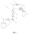
- Fig. 1 shows schematically a first embodiment of a vapour recovery system according to the present invention.
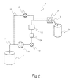
- Fig. 2 shows schematically a second embodiment of a vapour recovery system according to the present invention.
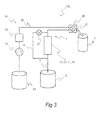
- Fig. 3 shows schematically a fuel dispensing apparatus having a vapour recovery system according to the present invention.
- the vapour recovery system according to the present invention for recovering vapour from a motor vehicle tank during filling-up has a first vapour path, drawing vapour from the vehicle tank to a vapour tank.
- the vapour flow rate is measured by a flow rate measuring means.
- the built-in control of the vapour recovery system according to the present invention is activated.
- a valve arranged in the vapour path is closed and at the same time a valve arranged in a second path is opened.
- the second path is connected to the first path downstream of the valve arranged in the first path.
- the vapour pump draws vapour (or any other gas present in the second path, e.g. air) through the second path and through the flow meter measuring means.
- the flow meter measuring means performs a new measurement, resulting in a new measured flow rate. This second flow rate is compared to the measured vapour flow rate in order to detect malfunction of the vapour recovery system.
- a first embodiment of a vapour recovery system 1 conveys fuel vapour from a motor vehicle tank 3 to a vapour tank 9 along a first vapour path 7.
- One end of the vapour path 7 is arranged via a valve 21 within a fuel dispensing nozzle 5.
- a vapour pump 11, a valve 19, a damper 23 and a flow rate measuring means 13 are arranged in the first vapour path 7.
- a second path 15 is at one end connected to the first vapour path 7, and the other end is an open end connected to the atmosphere.
- a valve 17 is arranged in the second path 15.
- the damper 23 is preferably incorporated in the first vapour path 7 in order to reduce variations in vapour flow so that the vapour pump 11 is exposed to a uniform vapour flow.
- the damper 23 can be of a simple construction, e.g. a fixed volume.
- valve 17 During the filling-up of a vehicle, the valve 17 is closed.
- the valves 21 and 19 are open and the vapour pump 11 is activated. Vapour is thereby drawn from the motor vehicle tank 3 through the valve 21.
- the vapour enters the flow rate measuring means 13, flows through the damper 23 and is accumulated in the vapour tank 9.
- the flow rate measuring means 13 measures the flow rate of vapour.
- the measured flow rate is compared to a reference flow rate corresponding to the actual speed of the vapour pump 11.
- a comparing means (not shown) is connected to the flow rate measuring means 13 and the vapour pump 11 so that a specific pump speed corresponds to a specific reference flow rate.
- the valve 21 is closed and the fuel dispensing nozzle 5 is detached from the motor vehicle tank 3. If the measured vapour flow rate equals the reference flow rate, or lies within a predetermined interval from the reference volume, the vapour recovery system 1 is considered to operate satisfactory and no further action is needed. If the measured flow rate lies outside the predetermined range, the vapour recovery system 1 is considered to malfunction and the built-in control of the vapour recovery system 1 is activated.
- the valve 17 is opened, and the vapour pump 11 draws air from the open end of the second path 15 through the second path 15, the flow rate measuring means 13, the damper 23, the valve 19 and down to the vapour tank 9.
- the flow rate measuring means 13 measures a new flow rate of air, and the measured new flow rate is compared to a new reference flow rate corresponding to the actual speed of the vapour pump 11. If the measured new flow rate lies within a predetermined range, the vapour recovery system 1 is considered to malfunction upstream of where the second path 15 connects to the first path 7. If the measured new flow rate lies outside the predetermined range, the vapour recovery system 1 is considered to malfunction downstream of where the second path 15 connects to the first path 7. Information related to any of these conclusions is e.g.
- a memory circuit (not shown) connected to the flow rate measuring means 13.
- Further equipment (not shown) is used to let an operator receive said information. Such equipment may e.g. enable wireless transmission of the information to a server. Malfunction as described above may e.g. be a result of dust particles which have been drawn into the first vapour path 7 via the fuel dispensing nozzle 5.
- the flow rate measuring means 13, the damper 23, the valve 19 and the fuel pump 11 may be arranged in another order along the first vapour path 7 than is shown in fig. 1 . Further components may also be arranged in the first vapour path 7 in order to enhance the function or efficiency of the vapour recovery system 1.
- no reference flow rate is provided.
- the valve 21 is closed and the fuel dispensing nozzle 5 is detached from the motor vehicle tank 3.
- the built-in control of the vapour recovery system is activated whereby the valve 17 is opened, and the vapour pump 11, operating at the same speed as during the previously performed filling-up, draws air from the open end of the second path 15 through the second path 15, the flow rate measuring means 13, the damper 23, the valve 19 and down to the vapour tank 9.
- the flow rate measuring means 13 measures a new flow rate of air.
- the built-in control is activated after each filling-up, or after a predetermined number of filling-ups. In one method, the built-in control is activated after each 10 th filling-up.
- the built-in control of the vapour recovery system is active for a predetermined time that can be adjusted to fit to the surrounding equipment (i.e. the fuel dispensing unit).
- the built-in control of the vapour recovery system may be active 1-60 seconds, preferably 1-20 seconds or more preferably 5-10 seconds.
- vapour recovery system 1 operates similarly to the vapour recovery system 1 shown in fig. 1 , and the first vapour path 7 is identical with the first vapour path 7 shown in fig. 1 , with the same reference numerals.
- One end of the second path 15 is connected to the first path 7 similarly to the embodiment shown in fig. 1 , and the other end is connected to the first path 7 downstream of the vapour pump 11 and the flow rate measuring means 13.
- the second path 15 forms a closed loop with the first vapour path 7.
- the valve 21 When the built-in control of the vapour recovery system 1 shown in fig. 2 is active, the valve 21 is closed and the valve 17 is opened.
- the vapour pump 11 draws vapour from the damper 23, the flow rate measuring means 13 and the second path 15 which is connected to the first path 7 downstream of the vapour pump 11 and thereby to the vapour tank 9.
- the flow rate measuring means 13 measures a new flow rate of vapour, and if the measured new flow rate lies within a predetermined range, the vapour recovery system 1 is considered to malfunction upstream of where the second path 15 connects to the first path 7 (upstream of the flow rate measuring means 13). If the measured new volume lies outside the predetermined range, the vapour recovery system 1 is considered to malfunction somewhere between the two positions where the second path 15 connects to the first path 7. Similar to what is described above, information about these conclusion is stored and accessible.
- a fuel dispensing unit 100 is shown schematically.
- the fuel dispensing unit 100 has a fuel dispensing means 50 and a vapour recovery system 1 according to the present invention.
- the fuel dispensing means 50 has a fuel pump 54 that draws fuel from a fuel tank 58, via a fuel path 52 through a flow meter 56 and to a fuel dispensing nozzle 5.
- the fuel dispensing nozzle 5 is connected to a motor vehicle tank 3.
- the fuel pump 54 is activated, and the flow meter 56 measures a volume of dispensed fuel.
- the flow meter 56 and the fuel pump 54 are connected to control means (not shown) for adjusting the speed of the fuel pump 54.
- the measured volume of dispensed fuel is transmitted to a second control means (not shown) for adjusting the speed of the vapour pump 23.
- the vapour recovery system 1 having the valve 17 closed, operates so that vapour is recovered from the motor vehicle tank 3.
- the fuel tank 58 and the vapour tank 9 can be arranged as one single unit.
- the valve 21 has two separate valves, one positioned inside the fuel path 52 and one positioned inside the vapour path 7.
- the two valves arranged in the valve 21 are automatically closed when the nozzle 5 is put in a vertical direction, i.e. after filling-up is finished.
- the vapour recovery system 1 enables the built-in control to be performed when said valves 21 are closed i.e. at any time before or after filling-up.
- the second path 15 of the vapour recovery system 1 can be open ended as shown in fig. 1 .
- the flow rate measuring means 13, the vapour pump 11, the damper 23 and the valve 19 can be arranged in any order along the first vapour path 7 as indicated in fig. 3 .
- Further components may be arranged in the first vapour path 7 in order to enhance the function or efficiency of the vapour recovery system 1.
Abstract
Description
- The present invention relates to a vapour recovery system for recovering vapour from a motor vehicle tank via a fuel dispensing nozzle. The present invention also relates to a method for control of a vapour recovery system for recovering vapour from a motor vehicle tank, and to a fuel dispensing apparatus for dispensing fuel to a motor vehicle.
- When filling the tank of a motor vehicle, it is a common measure to recover the vapour escaping the tank when filling it with liquid fuel from a fuel pump unit. The vapour recovery is performed by a system which is incorporated in the fuel pump unit, such that vapour of hydrocarbons are prevented from escaping to the environment outside the tank of the motor vehicle. Such vapour recovery system typically consists of a vapour inlet arranged in a fuel dispensing nozzle, a vapour pump and a flow meter. The recovered vapour is accumulated in a vapour tank. The vapour pump draws fuel vapour from the tank of the motor vehicle, through the flow meter and to the vapour tank. The flow meter measures the vapour flow and compares the measured value with the flow of dispensed fuel. Adjusting means are connected to the flow meter and to the vapour pump so that the vapour flow matches the flow of the dispensed fuel.
- Since a vapour recovery system consists of several components, there are several possible causes for such vapour recovery system to malfunction. If the value measured by the flow meter drops, this might be due to e.g. pump failure, flow meter failure, or dust, particles or other obstruction in the vapour line. Thus, there is a need for checking the correct operation of a vapour recovery system.
-
GB 2352437 - It is an object of the present invention to provide an improvement of the above techniques and prior art. More particularly, it is an object of the present invention to provide a built-in control of a vapour recovery system for recovering vapour from a motor vehicle tank via a fuel dispensing nozzle.
- The above objective is achieved according to a first aspect of the invention by a vapour recovery system for recovering vapour from a motor vehicle tank via a fuel dispensing nozzle, said system comprising a first vapour path between the fuel dispensing nozzle and a vapour tank, a vapour pump arranged in said first path and configured to pump vapour from the motor vehicle tank to the vapour tank, and a flow rate measuring means arranged in said first path. The system is characterised in that the vapour recovery system further comprises a second path which has a valve and one end of which is connected to the first path downstream of the fuel dispensing nozzle and upstream of the flow rate measuring means and the vapour pump. This is advantageous in that control of functionality of the vapour recovery system is possible in a simple way.
- The first path may comprise a valve arranged downstream of the fuel dispensing nozzle. Thus, the first vapour path can be shut off during e.g. service operations.
- The first path may comprise a valve arranged within the fuel dispensing nozzle, which is advantageous in that a minimum amount of vapour is present in the first path when the path is shut off.
- The other end of the second path may be connected to the atmosphere. This is advantageous in that the control can be performed at atmospheric pressure.
- The other end of the second path may be connected to the first path downstream of the flow rate measuring means and the vapour pump and upstream of the vapour tank. This is advantageous in that the second path is a closed circuit, whereby the risk of contamination is minimised.
- The above objective is achieved according to a second aspect of the invention by a method for control of a vapour recovery system for recovering vapour from a motor vehicle tank, said method comprising the steps of measuring a vapour recovery flow rate through a first vapour path between a fuel dispensing nozzle and a vapour tank and including a vapour pump and a flow rate measuring means. The method is characterised in that a second flow rate is measured through a second path one end of which is connected to the first path downstream of the fuel dispensing nozzle and upstream of the flow rate measuring means and the vapour pump, and in that the method comprises the step of comparing the measured vapour recovery flow rate with the second flow rate in order to detect malfunction of the vapour recovery system. The advantages of the first aspect of the invention are also applicable to this second aspect of the invention.
- The second flow rate may be measured through a second path the other end of which is connected to the atmosphere.
- The second flow rate may be measured through a second path the other end of which is connected to the first path downstream of the flow rate measuring means and the vapour pump and upstream of the vapour tank.
- The measured vapour recovery flow rate may be compared to a reference flow rate, and the step of measuring the second flow rate is performed if the measured vapour recovery flow rate differs from the reference flow rate.
- The vapour recovery flow rate and the second flow rate may be measured at the same speed of the vapour pump.
- The above objective is also achieved according to a third aspect of the invention by a fuel dispensing apparatus for dispensing fuel to a motor vehicle comprising fuel dispensing means and a vapour recovery system according to the first aspect of the invention.
- Other objectives, features and advantages of the present invention will appear from the following detailed disclosure, from the attached claims as well as from the drawings.
- Embodiments of the present invention will now be described in more detail, by way of examples, with reference to the accompanying drawings, in which
-
Fig. 1 shows schematically a first embodiment of a vapour recovery system according to the present invention. -
Fig. 2 shows schematically a second embodiment of a vapour recovery system according to the present invention. -
Fig. 3 shows schematically a fuel dispensing apparatus having a vapour recovery system according to the present invention. - The vapour recovery system according to the present invention for recovering vapour from a motor vehicle tank during filling-up has a first vapour path, drawing vapour from the vehicle tank to a vapour tank. The vapour flow rate is measured by a flow rate measuring means. After filling-up is finished, the built-in control of the vapour recovery system according to the present invention is activated. A valve arranged in the vapour path is closed and at the same time a valve arranged in a second path is opened. The second path is connected to the first path downstream of the valve arranged in the first path. Thus, the vapour pump draws vapour (or any other gas present in the second path, e.g. air) through the second path and through the flow meter measuring means. The flow meter measuring means performs a new measurement, resulting in a new measured flow rate. This second flow rate is compared to the measured vapour flow rate in order to detect malfunction of the vapour recovery system.
- In
fig. 1 , a first embodiment of avapour recovery system 1 is shown. Thevapour recovery system 1 conveys fuel vapour from amotor vehicle tank 3 to avapour tank 9 along afirst vapour path 7. One end of thevapour path 7 is arranged via avalve 21 within a fuel dispensing nozzle 5. Avapour pump 11, avalve 19, adamper 23 and a flow rate measuring means 13 are arranged in thefirst vapour path 7. Asecond path 15 is at one end connected to thefirst vapour path 7, and the other end is an open end connected to the atmosphere. Avalve 17 is arranged in thesecond path 15. Thedamper 23 is preferably incorporated in thefirst vapour path 7 in order to reduce variations in vapour flow so that thevapour pump 11 is exposed to a uniform vapour flow. Thedamper 23 can be of a simple construction, e.g. a fixed volume. - During the filling-up of a vehicle, the
valve 17 is closed. Thevalves vapour pump 11 is activated. Vapour is thereby drawn from themotor vehicle tank 3 through thevalve 21. The vapour enters the flow rate measuring means 13, flows through thedamper 23 and is accumulated in thevapour tank 9. The flow rate measuring means 13 measures the flow rate of vapour. - According to a first method, the measured flow rate is compared to a reference flow rate corresponding to the actual speed of the
vapour pump 11. Thus, a comparing means (not shown) is connected to the flow rate measuring means 13 and thevapour pump 11 so that a specific pump speed corresponds to a specific reference flow rate. After filling-up, thevalve 21 is closed and the fuel dispensing nozzle 5 is detached from themotor vehicle tank 3. If the measured vapour flow rate equals the reference flow rate, or lies within a predetermined interval from the reference volume, thevapour recovery system 1 is considered to operate satisfactory and no further action is needed. If the measured flow rate lies outside the predetermined range, thevapour recovery system 1 is considered to malfunction and the built-in control of thevapour recovery system 1 is activated. Thevalve 17 is opened, and thevapour pump 11 draws air from the open end of thesecond path 15 through thesecond path 15, the flow rate measuring means 13, thedamper 23, thevalve 19 and down to thevapour tank 9. The flow rate measuring means 13 measures a new flow rate of air, and the measured new flow rate is compared to a new reference flow rate corresponding to the actual speed of thevapour pump 11. If the measured new flow rate lies within a predetermined range, thevapour recovery system 1 is considered to malfunction upstream of where thesecond path 15 connects to thefirst path 7. If the measured new flow rate lies outside the predetermined range, thevapour recovery system 1 is considered to malfunction downstream of where thesecond path 15 connects to thefirst path 7. Information related to any of these conclusions is e.g. stored in a memory circuit (not shown) connected to the flow rate measuring means 13. Further equipment (not shown) is used to let an operator receive said information. Such equipment may e.g. enable wireless transmission of the information to a server. Malfunction as described above may e.g. be a result of dust particles which have been drawn into thefirst vapour path 7 via the fuel dispensing nozzle 5. The flow rate measuring means 13, thedamper 23, thevalve 19 and thefuel pump 11 may be arranged in another order along thefirst vapour path 7 than is shown infig. 1 . Further components may also be arranged in thefirst vapour path 7 in order to enhance the function or efficiency of thevapour recovery system 1. - According to a second method of the present invention, no reference flow rate is provided. After filling-up, the
valve 21 is closed and the fuel dispensing nozzle 5 is detached from themotor vehicle tank 3. The built-in control of the vapour recovery system is activated whereby thevalve 17 is opened, and thevapour pump 11, operating at the same speed as during the previously performed filling-up, draws air from the open end of thesecond path 15 through thesecond path 15, the flow rate measuring means 13, thedamper 23, thevalve 19 and down to thevapour tank 9. The flow rate measuring means 13 measures a new flow rate of air. If the measured flow rate does not equal the measured vapour flow rate, or lies outside a predetermined range from the measured vapour flow rate, a malfunction of the vapour recovery system is considered to be present somewhere in the first path upstream of where the second path is connected. Such malfunction may e.g. be an effect of a constriction in the first vapour path, e.g. in the fuel dispensing nozzle. The built-in control is activated after each filling-up, or after a predetermined number of filling-ups. In one method, the built-in control is activated after each 10th filling-up. - The built-in control of the vapour recovery system is active for a predetermined time that can be adjusted to fit to the surrounding equipment (i.e. the fuel dispensing unit). The built-in control of the vapour recovery system may be active 1-60 seconds, preferably 1-20 seconds or more preferably 5-10 seconds.
- In
fig. 2 , a further embodiment of avapour recovery system 1 is shown. Thevapour recovery system 1 operates similarly to thevapour recovery system 1 shown infig. 1 , and thefirst vapour path 7 is identical with thefirst vapour path 7 shown infig. 1 , with the same reference numerals. One end of thesecond path 15 is connected to thefirst path 7 similarly to the embodiment shown infig. 1 , and the other end is connected to thefirst path 7 downstream of thevapour pump 11 and the flow rate measuring means 13. Thus, thesecond path 15 forms a closed loop with thefirst vapour path 7. - When the built-in control of the
vapour recovery system 1 shown infig. 2 is active, thevalve 21 is closed and thevalve 17 is opened. Thevapour pump 11 draws vapour from thedamper 23, the flow rate measuring means 13 and thesecond path 15 which is connected to thefirst path 7 downstream of thevapour pump 11 and thereby to thevapour tank 9. According to the second method disclosed herein, the flow rate measuring means 13 measures a new flow rate of vapour, and if the measured new flow rate lies within a predetermined range, thevapour recovery system 1 is considered to malfunction upstream of where thesecond path 15 connects to the first path 7 (upstream of the flow rate measuring means 13). If the measured new volume lies outside the predetermined range, thevapour recovery system 1 is considered to malfunction somewhere between the two positions where thesecond path 15 connects to thefirst path 7. Similar to what is described above, information about these conclusion is stored and accessible. - In
fig. 3 , afuel dispensing unit 100 is shown schematically. Thefuel dispensing unit 100 has a fuel dispensing means 50 and avapour recovery system 1 according to the present invention. The fuel dispensing means 50 has afuel pump 54 that draws fuel from afuel tank 58, via a fuel path 52 through aflow meter 56 and to a fuel dispensing nozzle 5. During the filling-up of a vehicle, the fuel dispensing nozzle 5 is connected to amotor vehicle tank 3. Thefuel pump 54 is activated, and theflow meter 56 measures a volume of dispensed fuel. Theflow meter 56 and thefuel pump 54 are connected to control means (not shown) for adjusting the speed of thefuel pump 54. The measured volume of dispensed fuel is transmitted to a second control means (not shown) for adjusting the speed of thevapour pump 23. Thevapour recovery system 1, having thevalve 17 closed, operates so that vapour is recovered from themotor vehicle tank 3. Thefuel tank 58 and thevapour tank 9 can be arranged as one single unit. - The
valve 21 has two separate valves, one positioned inside the fuel path 52 and one positioned inside thevapour path 7. The two valves arranged in thevalve 21 are automatically closed when the nozzle 5 is put in a vertical direction, i.e. after filling-up is finished. Thevapour recovery system 1 enables the built-in control to be performed when saidvalves 21 are closed i.e. at any time before or after filling-up. - The
second path 15 of thevapour recovery system 1 can be open ended as shown infig. 1 . - The flow rate measuring means 13, the
vapour pump 11, thedamper 23 and thevalve 19 can be arranged in any order along thefirst vapour path 7 as indicated infig. 3 . - Further components may be arranged in the
first vapour path 7 in order to enhance the function or efficiency of thevapour recovery system 1. - The invention has mainly been described above with reference to a few preferred embodiments. However, as is readily appreciated by a person skilled in the art, other embodiments than the ones disclosed above are equally possible within the scope of the invention, as defined by the appended claims.
Claims (11)
- A vapour recovery system for recovering vapour from a motor vehicle tank (3) via a fuel dispensing nozzle (5), said system comprising
a first vapour path (7) between the fuel dispensing nozzle (5) and a vapour tank (9),
a vapour pump (11) arranged in said first path (7) and configured to pump vapour from the motor vehicle tank (3) to the vapour tank (9), and
a flow rate measuring means (13) arranged in said first path (7),
characterised in that
the vapour recovery system further comprises a second path (15) which has a valve (17) and one end of which is connected to the first path (7) downstream of the fuel dispensing nozzle (5) and upstream of the flow rate measuring means (13) and the vapour pump (11). - A vapour recovery system according to claim 1, wherein the first path (7) comprises a valve (19) arranged downstream of the fuel dispensing nozzle (5).
- A vapour recovery system according to any one of claims 1 or 2, wherein the first path (7) comprises a valve (21) arranged within the fuel dispensing nozzle (5).
- A vapour recovery system according to any one of claims 1-3, wherein the other end of the second path (15) is connected to the atmosphere.
- A vapour recovery system according to any one of claims 1-3, wherein the other end of the second path (15) is connected to the first path (7) downstream of the flow rate measuring means (13) and the vapour pump (11) and upstream of the vapour tank (9).
- A method for control of a vapour recovery system for recovering vapour from a motor vehicle tank, said method comprising the steps of
measuring a vapour recovery flow rate through a first vapour path between a fuel dispensing nozzle and a vapour tank and including a vapour pump and a flow rate measuring means,
characterised in that
a second flow rate is measured through a second path one end of which is connected to the first path downstream of the fuel dispensing nozzle and upstream of the flow rate measuring means and the vapour pump, and
comparing the measured vapour recovery flow rate with the second flow rate in order to detect malfunction of the vapour recovery system. - A method according to claim 6, wherein the second flow rate is measured through a second path the other end of which is connected to the atmosphere.
- A method according to claim 6, wherein the second flow rate is measured through a second path the other end of which is connected to the first path downstream of the flow rate measuring means and the vapour pump and upstream of the vapour tank.
- A method according to any one of claims 6-8, wherein the measured vapour recovery flow rate is compared to a reference flow rate, and wherein the step of measuring the second flow rate is performed if the measured vapour recovery flow rate differs from the reference flow rate.
- A method according to any one of claims 6-8, wherein the vapour recovery flow rate and the second flow rate are measured at the same speed of the vapour pump.
- A fuel dispensing apparatus for dispensing fuel to a motor vehicle comprising fuel dispensing means (50) and a vapour recovery system according to any one of claims 1-5.
Priority Applications (1)
| Application Number | Priority Date | Filing Date | Title |
|---|---|---|---|
| EP07108807A EP1995209A1 (en) | 2007-05-24 | 2007-05-24 | A vapour recovery system, a method for control thereof, and a fuel dispensing apparatus |
Applications Claiming Priority (1)
| Application Number | Priority Date | Filing Date | Title |
|---|---|---|---|
| EP07108807A EP1995209A1 (en) | 2007-05-24 | 2007-05-24 | A vapour recovery system, a method for control thereof, and a fuel dispensing apparatus |
Publications (1)
| Publication Number | Publication Date |
|---|---|
| EP1995209A1 true EP1995209A1 (en) | 2008-11-26 |
Family
ID=38537788
Family Applications (1)
| Application Number | Title | Priority Date | Filing Date |
|---|---|---|---|
| EP07108807A Withdrawn EP1995209A1 (en) | 2007-05-24 | 2007-05-24 | A vapour recovery system, a method for control thereof, and a fuel dispensing apparatus |
Country Status (1)
| Country | Link |
|---|---|
| EP (1) | EP1995209A1 (en) |
Cited By (1)
| Publication number | Priority date | Publication date | Assignee | Title |
|---|---|---|---|---|
| EP2241532A1 (en) | 2009-04-15 | 2010-10-20 | Dresser Wayne AB | A fuel dispensing unit, and a method for controlling such a fuel dispensing unit |
Citations (2)
| Publication number | Priority date | Publication date | Assignee | Title |
|---|---|---|---|---|
| WO2000055047A1 (en) | 1999-03-18 | 2000-09-21 | Dresser, Inc. | Vapor recovery system and method with leakage and air flow sensing |
| GB2352437A (en) | 1999-07-23 | 2001-01-31 | Tokheim Services France | A method of checking the correct operation of a vapour recovery system |
-
2007
- 2007-05-24 EP EP07108807A patent/EP1995209A1/en not_active Withdrawn
Patent Citations (2)
| Publication number | Priority date | Publication date | Assignee | Title |
|---|---|---|---|---|
| WO2000055047A1 (en) | 1999-03-18 | 2000-09-21 | Dresser, Inc. | Vapor recovery system and method with leakage and air flow sensing |
| GB2352437A (en) | 1999-07-23 | 2001-01-31 | Tokheim Services France | A method of checking the correct operation of a vapour recovery system |
Cited By (1)
| Publication number | Priority date | Publication date | Assignee | Title |
|---|---|---|---|---|
| EP2241532A1 (en) | 2009-04-15 | 2010-10-20 | Dresser Wayne AB | A fuel dispensing unit, and a method for controlling such a fuel dispensing unit |
Similar Documents
| Publication | Publication Date | Title |
|---|---|---|
| US5857500A (en) | System and method for testing for error conditions in a fuel vapor recovery system | |
| US5988232A (en) | Vapor recovery system employing oxygen detection | |
| EP0982263B1 (en) | Fuel delivery system with vapour recovery testing mode | |
| WO2008053839A1 (en) | Diagnostic mechanism in differential pressure type mass flow controller | |
| US6336479B1 (en) | Determining vapor recovery in a fueling system | |
| EP3555576A1 (en) | Methods and apparatus for wide range mass flow verification | |
| US20080099097A1 (en) | Method of determining the gas return rate of filling pumps | |
| US20140283582A1 (en) | Method And Apparatus For Determining The Thermal Status Of Fuel In A Line Leak Detection System | |
| AU7167700A (en) | A method and apparatus for diagnosing the status of a hydrocarbon sensor | |
| EP1995209A1 (en) | A vapour recovery system, a method for control thereof, and a fuel dispensing apparatus | |
| EP3385690B1 (en) | Aircraft fluid control system having a pressure sensor | |
| US6247508B1 (en) | Vapor recovery system and method with leakage and air flow sensing | |
| EP2113751A1 (en) | Liquid flow monitoring system | |
| EP1739053B1 (en) | Fuel vapour recovery system with temperature sensor and method therefor | |
| US10207134B2 (en) | System and method for testing a fire suppression system | |
| CN108152061B (en) | Side window pressure detection system and method | |
| EP2050711B1 (en) | Vapour recovery detection means | |
| EP2241532B1 (en) | A fuel dispensing unit, and a method for controlling such a fuel dispensing unit | |
| HUT62239A (en) | Fuel feeding device | |
| EP1898186A1 (en) | Method and apparatus for detecting gas bubble content of flowing fluid | |
| RU2020129348A (en) | FILLING DEVICE FOR AIRCRAFT, METHOD OF COMMISSIONING AND METHOD OF REFUELING USING SUCH DEVICE | |
| US20010022202A1 (en) | Vapor recovery system and method with leakage and air flow sensing | |
| EP2116506A1 (en) | Vapour recovery regulation | |
| MXPA00003663A (en) | Vapor recovery system employing oxygen detection |
Legal Events
| Date | Code | Title | Description |
|---|---|---|---|
| PUAI | Public reference made under article 153(3) epc to a published international application that has entered the european phase |
Free format text: ORIGINAL CODE: 0009012 |
|
| AK | Designated contracting states |
Kind code of ref document: A1 Designated state(s): AT BE BG CH CY CZ DE DK EE ES FI FR GB GR HU IE IS IT LI LT LU LV MC MT NL PL PT RO SE SI SK TR |
|
| AX | Request for extension of the european patent |
Extension state: AL BA HR MK RS |
|
| 17P | Request for examination filed |
Effective date: 20090526 |
|
| AKX | Designation fees paid |
Designated state(s): AT BE BG CH CY CZ DE DK EE ES FI FR GB GR HU IE IS IT LI LT LU LV MC MT NL PL PT RO SE SI SK TR |
|
| 17Q | First examination report despatched |
Effective date: 20111103 |
|
| RAP1 | Party data changed (applicant data changed or rights of an application transferred) |
Owner name: DRESSER WAYNE AB |
|
| STAA | Information on the status of an ep patent application or granted ep patent |
Free format text: STATUS: THE APPLICATION IS DEEMED TO BE WITHDRAWN |
|
| 18D | Application deemed to be withdrawn |
Effective date: 20151201 |