EP2593155B1 - Dispositif d'aspiration pour évacuer des fumées - Google Patents
Dispositif d'aspiration pour évacuer des fumées Download PDFInfo
- Publication number
- EP2593155B1 EP2593155B1 EP11867832.5A EP11867832A EP2593155B1 EP 2593155 B1 EP2593155 B1 EP 2593155B1 EP 11867832 A EP11867832 A EP 11867832A EP 2593155 B1 EP2593155 B1 EP 2593155B1
- Authority
- EP
- European Patent Office
- Prior art keywords
- suction
- suction device
- support member
- tongue
- tongue blade
- Prior art date
- Legal status (The legal status is an assumption and is not a legal conclusion. Google has not performed a legal analysis and makes no representation as to the accuracy of the status listed.)
- Active
Links
- 239000003517 fume Substances 0.000 title claims description 28
- 239000000835 fiber Substances 0.000 claims description 11
- 239000004033 plastic Substances 0.000 claims description 5
- 229910001220 stainless steel Inorganic materials 0.000 claims description 3
- 239000010935 stainless steel Substances 0.000 claims description 3
- 230000000881 depressing effect Effects 0.000 claims 1
- 210000000214 mouth Anatomy 0.000 description 34
- 210000001519 tissue Anatomy 0.000 description 28
- 239000000779 smoke Substances 0.000 description 26
- 230000001473 noxious effect Effects 0.000 description 17
- 238000001356 surgical procedure Methods 0.000 description 12
- 239000012530 fluid Substances 0.000 description 6
- 230000000694 effects Effects 0.000 description 5
- 239000003994 anesthetic gas Substances 0.000 description 4
- 238000000034 method Methods 0.000 description 4
- 210000003300 oropharynx Anatomy 0.000 description 4
- 210000002396 uvula Anatomy 0.000 description 4
- 230000004075 alteration Effects 0.000 description 2
- QVGXLLKOCUKJST-UHFFFAOYSA-N atomic oxygen Chemical compound [O] QVGXLLKOCUKJST-UHFFFAOYSA-N 0.000 description 2
- 210000004373 mandible Anatomy 0.000 description 2
- 239000000463 material Substances 0.000 description 2
- 238000012986 modification Methods 0.000 description 2
- 230000004048 modification Effects 0.000 description 2
- 239000001301 oxygen Substances 0.000 description 2
- 229910052760 oxygen Inorganic materials 0.000 description 2
- 230000001681 protective effect Effects 0.000 description 2
- 229910000811 surgical stainless steel Inorganic materials 0.000 description 2
- 239000010966 surgical stainless steel Substances 0.000 description 2
- 238000002627 tracheal intubation Methods 0.000 description 2
- 206010041235 Snoring Diseases 0.000 description 1
- 238000002679 ablation Methods 0.000 description 1
- 238000011109 contamination Methods 0.000 description 1
- 238000002316 cosmetic surgery Methods 0.000 description 1
- 230000001419 dependent effect Effects 0.000 description 1
- 239000007789 gas Substances 0.000 description 1
- 230000002452 interceptive effect Effects 0.000 description 1
- 238000002430 laser surgery Methods 0.000 description 1
- 210000002741 palatine tonsil Anatomy 0.000 description 1
- 230000001012 protector Effects 0.000 description 1
- 239000002516 radical scavenger Substances 0.000 description 1
- 238000002271 resection Methods 0.000 description 1
- 210000003296 saliva Anatomy 0.000 description 1
- 238000011012 sanitization Methods 0.000 description 1
- 210000001584 soft palate Anatomy 0.000 description 1
- 229920001169 thermoplastic Polymers 0.000 description 1
- 239000004416 thermosoftening plastic Substances 0.000 description 1
- 238000007483 tonsillectomy Methods 0.000 description 1
Images


Classifications
-
- A—HUMAN NECESSITIES
- A61—MEDICAL OR VETERINARY SCIENCE; HYGIENE
- A61C—DENTISTRY; APPARATUS OR METHODS FOR ORAL OR DENTAL HYGIENE
- A61C17/00—Devices for cleaning, polishing, rinsing or drying teeth, teeth cavities or prostheses; Saliva removers; Dental appliances for receiving spittle
- A61C17/06—Saliva removers; Accessories therefor
- A61C17/08—Aspiration nozzles
Definitions
- the disclosure relates generally to the field of surgical instrumentation and more particularly, to a suction device to be used with a tongue blade device for evacuating cauterization tissue and fumes from a patient's mouth during oral laser surgery.
- Electrocautery devices and surgical lasers are typically used for cutting or ablating tissues in various confined body cavities. For example, in the surgical treatment of snoring, the surgeon performs a vertical resection of the soft palate on both sides of the uvula, sparing the uvula itself, with further ablation with the laser of the lateral and inferior sides of the uvula to create a "new uvula" that is higher and smaller (uvulopalatoplasty). Electrocautery devices and surgical lasers are also used for reshaping or removing the tonsils (tonsillectomy), and for removing or reshaping posterior parts of the tongue (glossectomy).
- a tongue blade evacuation system can be provided as shown in U.S. Patent No. 5,460,626 . It is also necessary that the patient's tongue be kept away from the working area. These requirements are necessary to provide a clear view of the working area for the surgeon.
- the device is a tongue blade used with a Mclvor mouthgag.
- the device is used intraoperatively to retract the tongue and mandible and open the mouth for surgeries involving the oral cavity/oropharynx.
- the device is preferably a one-piece surgical stainless steel unit with a built-in suction tube to evacuate any anesthetic gases or noxious/dangerous fumes or plumes generated by electrocautery, or other similar devices. This serves as a protective feature to help ensure the safety of the Operating Room Staff and the patient. It can also be used to oxygenate or jet ventilate a patient intraoperatively by passing oxygen through the suction passage down into the oral cavity/oropharynx.
- a high impact plastic model that is disposable
- a stainless steel model with a removable, disposable suction tubing can be two other variations of the device: a high impact plastic model that is disposable, and a stainless steel model with a removable, disposable suction tubing.
- US4947896 discloses a laryngoscope having a blade and a removably attached handle, which can be fixed to the blade at a desired angle.
- An adjustable position suction tube is entrained in the blade with an adjustment actuator supported on the handle.
- US5078602 discloses a saliva ejector including a hollow tube soldered to a side of a tongue protector.
- US6254591 discloses a medical scavenger suction device which includes a tubing assembly having a primary tube and two or more auxiliary tube members.
- the tubing assembly is integrally formed within an endotracheal tube sidewall or formed integrally with a mouth gag device.
- the tubing assembly is adapted to connect to standard wall suction tubing to enable the exhausting of gas and/or smoke from the surgical area.
- US1613373 discloses a combined suction tube and tongue depressor.
- US4215984 discloses a dental suction device in which the generally hollow U-shaped base of the device is designed to be positioned in a patient's lower jaw area inside the lower row of teeth.
- the base is connected to a hollow, curved stem which can be connected to a suction source. Slots in the base are utilized to ingest excess moisture present in a patient's mouth during dental procedures.
- the device also has a flat plate attached to the base which acts as a tongue depressor and an adjustable tooth rest on the stem on which a patient's upper maxillary incisal teeth rest during dental procedures.
- US2010121152 discloses a laryngoscope with a suction catheter assembly that includes a catheter to supply suction for removal of fluids proximate to the distal end of the blade of the laryngoscope during intubation.
- a connector secures the catheter to the distal end of the blade.
- a retainer holds the catheter against the side of the blade.
- US2007287888 discloses a suction unit which is placed inside the handle of a laryngoscope to allow portable suction to be utilized during intubation without requiring multiple devices.
- the suction tip can be attached to the distal end of the laryngoscope blade.
- the present invention provides a suction device as defined in claim 1.
- Optional features are recited in dependent claims.
- the disclosure relates to an apparatus for removing noxious fumes.
- it relates to an apparatus for and a method which does not form part of the invention of removing noxious fumes, plumes generated by electrocautery, smoke and vaporized tissue from a patient's mouth and controlling a patient's tongue through the use of a one-piece tongue blade coupled with a suction device to form a single unit which can be used in and during surgical applications.
- the disclosure includes a tongue blade coupled with a suction device.
- a suction device for evacuating fumes has a tongue depressor including a pair of opposed walls; a suction tube connected to the tongue depressor; an elongated support member to which the suction tube is connected; and a connecting member attached to an end of the suction tube for connecting the suction tube to a suction generating device.
- FIGS. 1-1C show illustrations of a preferred embodiment of the disclosure including a tongue blade 10 having a distal end 12 for inserting into a patient's mouth during a surgical application and a proximal end 14 coupled in fluid communication with a hollow tube 16.
- the tongue blade has a curved or rounded shape body 18 which acts as a tongue depressor and rests on the patient's tongue.
- the distal end 12 has a fork or U-shaped appearance formed by two protrusions 22, 24 ( FIG. 1 B) extending therefrom which form a channel or opening 26. Protrusions 22, 24 extend or curve upwardly as seen in FIG. 1B .
- a disposable hollow plastic or rubber suction tube 16 is connected to an elongated spine 28 which is in communication with a barb or hollow connector 30.
- the spine is preferably formed from stainless steel or any other suitable material.
- the spine has a first elongated portion 31 and a shorter portion 33 which extends at about 90 degrees from end 35 of portion 31. Portion 33 has an opening 32 for receiving the tube 16 therethrough.
- the suction tube 16 has a receiving outlet member 34 having an opening 36 formed therethrough located adjacent to the proximal end 14 of the blade for removing anesthetic gases, noxious fumes, smoke, vaporized tissue, plumes generated by electrocautery and other debris from a patient's mouth during use in surgery.
- the spine 28 which is manually held in one of the doctor's hands, is held near the patient's mouth directing the suction tube 16 into the patient's mouth which removes smoke, fumes, plumes generated by electrocautery, and vaporized tissue from the patient's mouth using opening 36 ( FIG. 1 B) .
- the tongue blade 10, which is connected to the tube is in the patient's mouth controlling the patient's tongue, thus preventing the tongue from obstructing the application of the suction tube and removing smoke and vaporized tissue at the same time.
- the tongue blade suction tube 16 evacuates the smoke, fumes, plumes generated by electrocautery, and vaporized tissue by sucking it through the receiving port or opening 36, through tube 16, and out through any well known pneumatic or other suction causing device (not shown), attached to the tube barb 30.
- the device is a tongue blade 10 used with a Mclvor mouthgag.
- the device is used intraoperatively to retract the tongue and mandible and open the mouth for surgeries involving the oral cavity/oropharynx.
- the device 10 is preferably a one-piece surgical stainless steel tongue blade with a built-in suction tube 16 to evacuate any noxious/dangerous fumes or plumes generated by electrocautery, or other similar devices. This serves as a protective feature to help ensure the safety of the Operating Room Staff as well as the patient.
- the tongue blade and suction device can also be used to oxygenate or jet ventilate a patient intraoperatively by passing oxygen through the suction tube 16 down into the oral cavity/oropharynx through opening 36.
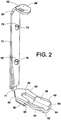
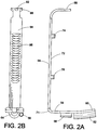
- FIGS. 2-2B and 3 show illustrations of an alternate configuration of the disclosure (not in accordance with the presently claimed invention) including a tongue blade 50 having a distal end 52 for inserting into a patient's mouth during a surgical application and a proximal end 54 coupled with a hollow tube receiving member 56 and an elongated support member or spine 70 via a curved connector 71.
- a substantially U-shaped opening 55 is formed near end 54.
- the tongue blade has a curved or rounded shape body 58 which acts as a tongue depressor and rests on the patient's tongue.
- the distal end 52 has a fork or U-shaped appearance formed by two protrusions or walls 60, 62 extending therefrom which form a rounded or curved channel 64 having opening 66.
- Walls 60, 62 curve upwardly as seen in FIG. 2A .
- a hollow disposable suction tube 70 is connected to elongated spine 72 and is in fluid communication with hollow connector or receiving member 56.
- the spine has a pair of cylindrical shaped members 74, 76 having openings 78, 80 formed therein for receiving the tube 70 therein.
- the suction tube receiving outlet member 56 has an opening 86 located adjacent to the proximal end 54 of the blade for removing noxious fumes, smoke, vaporized tissue, plumes generated by electrocautery and other debris from a patient's mouth during use in surgery.
- Spine 72 also has a wall 88 extending from end 90 which has an opening 92 therethrough for receiving tube 70.
- Wall 88 is bent at approximately 90 degrees with respect to spine 72.
- a plurality of gripping notches or knurl recesses 96 which provide an ergonomic manual grip for the user to grip and hold the spine.
- gripping members, protrusions or extensions 98 can be provided to also provide an ergonomic grip.
- the spine 72 which is held in one of the doctor's hands, is held near the patient's mouth directing the suction tube 70 in the patient's mouth and removing smoke, fumes, plumes generated by electrocautery, and vaporized tissue via opening 86.
- the tongue blade 50 which is connected to the tube, is in the patient's mouth controlling the patient's tongue, thus preventing it from obstructing the application and removing smoke and vaporized tissue at the same time.
- the tongue blade suction tube 70 meanwhile evacuates the smoke, fumes, plumes generated by electrocautery, and vaporized tissue by sucking it through the receiving port or opening 86, through tube 70, and out through the pneumatic or other suction causing device (not shown) attached to barb 93. After use, the suction tube 70 can be removed and discarded. The spine 72 can be sanitized and reused with a new suction tube.
- Another variation of the disclosure is a one-piece unit which is fabricated from a high impact plastic that is disposable.
- FIG. 4 shows an illustration of an alternate embodiment of the disclosure for a one-piece disposable tongue blade and suction device which can be fabricated of thermoplastic or any other suitable material. That is, the device can be used with one patient for a one-time use and then discarded or disposed.
- the device includes a tongue blade 100 having a distal end 102 for inserting into a patient's mouth during a surgical application and a proximal end 04 coupled in fluid communication with a hollow tube 106 integrally formed with the tongue blade.
- the tongue blade has a curved or rounded shape body 108 which acts as a tongue depressor and rests on the patient's tongue.
- the distal end 102 has a fork or U-shaped appearance formed by two protrusions 110, 112 extending therefrom and curved upwardly which form a channel or opening 116 therebetween.
- the hollow tube 106 extends from an elongated spine 18.
- the suction tube 106 has an opening 120 located adjacent to the proximal end 104 of the blade for removing noxious fumes, smoke, vaporized tissue, plumes generated by electrocautery and other debris from a patient's mouth during use in surgery.
- the spine 118 which is manually held in one of the doctor's hands, is held near the patient's mouth directing the suction tube 106 in the patient's mouth and removing smoke, fumes, plumes generated by electrocautery, and vaporized tissue via opening 120.
- the tongue blade 100 which is connected to the tube, is in the patient's mouth controlling the patient's tongue, thus preventing it from obstructing the application and removing smoke and vaporized tissue at the same time.
- the tongue blade suction tube 106 meanwhile evacuates the smoke, fumes, plumes generated by electrocautery, and vaporized tissue by sucking it through the receiving port or opening 120, through tube 106, and out through any well known device the pneumatic or other suction causing device (not shown), attached to the tube barb 122.
- FIGS. 6A-6C another alternate embodiment of the suction device is shown.
- the device is preferably used with a Dingman mouthgag such as used in plastic surgery.
- a fiber optic light also can be added to the device.
- This device can be one-piece and disposable as well.
- FIGS. 6A-6C show illustrations of an alternate embodiment of the disclosure including a tongue blade 140 having a distal end 142 for inserting into a patient's mouth during a surgical application and a proximal end 144 coupled with a hollow tube receiving members 146 and a ring or receiving member 147 for connecting a light such as a fiber optic light 180 and an elongated support member or spine 148.
- a substantially U-shaped opening 152 is formed in blade 140.
- the tongue blade has a curved or rounded shape body 156 which acts as a tongue depressor and rests on the patient's tongue.
- the U-shaped appearance is formed by two protrusions or walls 160, 162 extending therefrom which form a rounded or curved channel 164.
- Walls 160, 162 curve upwardly as seen in FIG. 6A .
- Hollow disposable suction tube 170 is connected to elongated spine 148 and is in fluid communication with hollow connector or receiving member 147.
- the ring or receiving outlet member 146 accommodates a light such as a fiber optic light 180 extending therefrom. Fiber optic light 180 can be attached via ring 146 for illuminating the patient's mouth.
- a connecting wire 182 extends from the light to an external power source (not shown).
- Tube 170 is located adjacent to the proximal end 142 of the blade for removing anesthetic gases, noxious fumes, smoke, vaporized tissue, plumes generated by electrocautery and other debris from a patient's mouth during use in surgery.
- Spine 148 also has a wall 184 extending from end 186 which has an opening 188 therethrough for receiving tube 170. Wall 184 is bent at approximately 90 degrees with respect to spine 148.
- On a rear side 190 of the spine are formed a plurality of gripping notches or knurl recesses 192 which provide an ergonomic manual grip for the user to grip and hold the spine.
- gripping members, protrusions or extensions can also be provided to also provide an ergonomic grip.
- FIGS. 7A-7C another alternate configuration of the suction device is shown (not in accordance with the presently claimed invention).
- FIGS. 7A-7C show illustrations of an alternate configuration of the disclosure including a tongue blade 200 having a distal end 202 for inserting into a patient's mouth during a surgical application and a proximal end 204 coupled with a pair of hollow tube receiving members 206, 208 and an elongated support member or spine 210 via a curved connector 212.
- a substantially U-shaped opening 214 is formed in blade 200.
- the tongue blade has a curved or rounded shape body 216 which acts as a tongue depressor and rests on the patient's tongue.
- the distal end 202 has a fork or U-shaped appearance formed by two protrusions or walls 218, 220 extending therefrom which form a rounded or curved channel 224 having opening 214.
- Walls 218, 220 curve upwardly as seen in FIG. 7B .
- a hollow disposable suction tube is connected to elongated spine 40 and is in fluid communication with one of hollow connector or receiving members 206, 208, such as shown in FIGS. 6A-6C .
- the suction tube receiving outlet members 206, 208 have openings 225, 226 located adjacent to the proximal end 204 of the blade for removing anesthetic gases, noxious fumes, smoke, vaporized tissue, plumes generated by electrocautery and other debris from a patient's mouth during use in surgery.
- One of the members 206, 208 can also accommodate a light such as a fiber optic light as shown in the embodiment of FIGS.
- the spine also has a wall 228 extending from end 230 which has an opening 232 therethrough for receiving portions of suction tubes or fiber optic lights therein.
- Wall 228 is bent at approximately 90 degrees with respect to the spine.
- On a rear side 233 of the spine are formed a plurality of gripping notches or knurl recesses 234 which provide an ergonomic manual grip for the user to grip and hold the spine.
- gripping members, protrusions or extensions can be provided to also provide an ergonomic grip.
- Rings or receiving members 236 and 238 are formed on a first side 240 of wall 210 to accommodate or retain a suction tube or a fiber optic light.
Landscapes
- Health & Medical Sciences (AREA)
- Dentistry (AREA)
- Epidemiology (AREA)
- Life Sciences & Earth Sciences (AREA)
- Animal Behavior & Ethology (AREA)
- General Health & Medical Sciences (AREA)
- Public Health (AREA)
- Veterinary Medicine (AREA)
- Surgical Instruments (AREA)
Claims (21)
- Dispositif d'aspiration destiné à évacuer des fumées, comprenant :une lame abaisse-langue (10) comprenant une paire de parois opposées et des première et seconde surfaces, ladite première surface (18) étant destinée à abaisser la langue d'un patient ;un tube d'aspiration (16) raccordé au niveau d'une première extrémité à ladite lame abaisse-langue (10) ;un élément de support allongé (28) auquel une seconde extrémité dudit tube d'aspiration (16) est raccordée ; etun élément de raccordement (30) fixé audit tube d'aspiration (16) destiné à raccorder ledit tube d'aspiration (16) à un dispositif de génération d'aspiration associé,caractérisé en ce que l'élément de support allongé (28) est une colonne et que le tube d'aspiration (16) est un tube creux rigide possédant une première partie allongée à laquelle la colonne (28) est raccordée, une seconde partie qui est incurvée et qui relie la colonne (28) et la lame abaisse-langue (10) ensemble de sorte que les forces entre la colonne (28) et la lame abaisse-langue (10) soient transférées à travers la deuxième partie, et une troisième partie raccordée à la lame abaisse-langue (10) sur la seconde surface de la lame abaisse-langue (10).
- Dispositif selon la revendication 1, ladite lame abaisse-langue (10) comprenant un corps possédant une configuration incurvée.
- Dispositif selon la revendication 1, ladite paire de parois opposées formant un canal sensiblement en forme de U.
- Dispositif selon la revendication 3, lesdites parois opposées se courbant vers le haut.
- Dispositif d'aspiration selon la revendication 1, ladite colonne (28) étant en acier inoxydable.
- Dispositif d'aspiration selon la revendication 1, ledit élément de support allongé (28) comprenant une ouverture (32) permettant de recevoir une seconde extrémité dudit tube d'aspiration (16).
- Dispositif d'aspiration selon la revendication 2, ledit corps de ladite lame abaisse-langue (10) comprenant une extrémité proximale et une extrémité distale.
- Dispositif d'aspiration selon la revendication 7, ledit tube d'aspiration (16) comprenant une ouverture (36) située de manière adjacente à ladite extrémité proximale dudit corps.
- Dispositif d'aspiration selon la revendication 1, ledit élément de support allongé (28) comprenant une première partie (31) et une deuxième partie (33) approximativement perpendiculaire à ladite première partie.
- Dispositif d'aspiration selon la revendication 1, ladite lame abaisse-langue (10), ledit tube d'aspiration (16) et ledit élément de support allongé (28) étant fabriqués sous la forme d'une unité monobloc comprenant ladite lame abaisse-langue, ledit tube d'aspiration et ledit élément de support allongé.
- Dispositif d'aspiration selon la revendication 10, ladite lame abaisse-langue (10), ledit tube d'aspiration (16) et ledit élément allongé (28) étant en matières plastiques.
- Dispositif d'aspiration selon la revendication 1, ledit élément de support allongé (28) comprenant au moins un élément de retenue destiné à fixer ledit tube d'aspiration (16) audit élément de support allongé (28).
- Dispositif d'aspiration selon la revendication 1, ledit élément de support allongé (28) comprenant une paire d'éléments de retenue destinés à fixer ledit tube d'aspiration (16) audit élément allongé (28).
- Dispositif d'aspiration selon la revendication 12, ledit élément de support allongé (28) comprenant une pluralité d'encoches de préhension destinées à faciliter la préhension dudit élément de support (28).
- Dispositif d'aspiration selon la revendication 12, ledit élément de support allongé (28) comprenant une pluralité d'éléments de préhension destinés à faciliter la préhension dudit élément de support (28).
- Dispositif d'aspiration selon la revendication 1, ladite lame abaisse-langue (10) comprenant un premier élément de retenue destiné à retenir ledit tube d'aspiration (16).
- Dispositif d'aspiration selon la revendication 16, ladite lame abaisse-langue (10) comprenant un second élément de retenue conçu pour retenir un éclairage.
- Dispositif d'aspiration selon la revendication 17,
ledit second élément de retenue étant conçu pour retenir un éclairage de fibre optique. - Dispositif d'aspiration selon la revendication 16, ledit premier élément de retenue comprenant un anneau.
- Dispositif d'aspiration selon la revendication 17, ledit second élément de retenue comprenant un anneau.
- Dispositif d'aspiration selon la revendication 17, ledit élément de support allongé (28) comprenant une paire d'éléments de retenue conçus pour fixer ladite lumière audit élément de support allongé (28).
Applications Claiming Priority (2)
| Application Number | Priority Date | Filing Date | Title |
|---|---|---|---|
| US36449910P | 2010-07-15 | 2010-07-15 | |
| PCT/US2011/023619 WO2012173586A1 (fr) | 2010-07-15 | 2011-02-03 | Dispositif d'aspiration pour évacuer des fumées |
Publications (3)
| Publication Number | Publication Date |
|---|---|
| EP2593155A1 EP2593155A1 (fr) | 2013-05-22 |
| EP2593155A4 EP2593155A4 (fr) | 2017-11-08 |
| EP2593155B1 true EP2593155B1 (fr) | 2019-06-26 |
Family
ID=45467270
Family Applications (1)
| Application Number | Title | Priority Date | Filing Date |
|---|---|---|---|
| EP11867832.5A Active EP2593155B1 (fr) | 2010-07-15 | 2011-02-03 | Dispositif d'aspiration pour évacuer des fumées |
Country Status (4)
| Country | Link |
|---|---|
| US (1) | US8852169B2 (fr) |
| EP (1) | EP2593155B1 (fr) |
| CA (1) | CA2805380C (fr) |
| WO (1) | WO2012173586A1 (fr) |
Families Citing this family (8)
| Publication number | Priority date | Publication date | Assignee | Title |
|---|---|---|---|---|
| US9788924B2 (en) | 2012-12-07 | 2017-10-17 | Dryshield, Llc | Intraoral device with bridge |
| US8911232B2 (en) | 2012-12-07 | 2014-12-16 | Incept, Inc. | Intraoral dental suction and isolation system |
| US20140257039A1 (en) * | 2013-03-08 | 2014-09-11 | Joel Feldman | Surgical retractor with smoke evacuator |
| US10390916B1 (en) * | 2013-12-13 | 2019-08-27 | Edmond Rassibi | Saliva ejector appliance |
| US9358086B2 (en) * | 2014-05-22 | 2016-06-07 | Innerlite, Inc. | Intraoral device and method of use |
| US11179225B2 (en) * | 2015-06-10 | 2021-11-23 | Essential Surgical Pty Ltd | Protective device for use in oral surgical procedures |
| US10548584B2 (en) * | 2016-09-27 | 2020-02-04 | Milo Medical Ip, Llc | Mouth gag |
| BR112021022474A2 (pt) | 2019-05-10 | 2022-01-04 | Dryshield Llc | Aparelho dentário |
Family Cites Families (17)
| Publication number | Priority date | Publication date | Assignee | Title |
|---|---|---|---|---|
| US1613373A (en) * | 1924-07-01 | 1927-01-04 | Foster A Beck | Combined suction tube and tongue depressor |
| US2697432A (en) * | 1952-03-07 | 1954-12-21 | Silas F Scinta | Mouth gag with anaesthetic tube for surgical use |
| US2756742A (en) | 1953-08-18 | 1956-07-31 | Barton Foundation | Endotracheal tongue blade with tube guide |
| US3154069A (en) * | 1962-07-31 | 1964-10-27 | Sorenson Res Corp | Grooved tongue depressor |
| US4064873A (en) | 1976-06-10 | 1977-12-27 | Swenson Rudolph E | Tongue blade for mouth gag |
| US4192071A (en) | 1978-01-30 | 1980-03-11 | Norman Erickson | Dental appliance |
| US4213451A (en) * | 1978-08-21 | 1980-07-22 | Swenson Rudolph E | Tongue blade for mouth gag for adults |
| US4215984A (en) | 1979-01-15 | 1980-08-05 | Reichley Joseph P | Dental suction device |
| US4562832A (en) | 1984-01-21 | 1986-01-07 | Wilder Joseph R | Medical instrument and light pipe illumination assembly |
| US4947896A (en) * | 1988-11-04 | 1990-08-14 | Bartlett Robert L | Laryngoscope |
| US5078602A (en) * | 1990-04-30 | 1992-01-07 | Geraldine Honoshofsky | Saliva ejector and method for cleaning the same |
| US5281134A (en) * | 1991-11-19 | 1994-01-25 | Schultz Allen J | Fiber optic illumination system for dental instruments |
| US5460626A (en) | 1994-04-06 | 1995-10-24 | Laser Industries, Ltd. | Tongue blade evacuation system |
| US6254591B1 (en) * | 1999-06-01 | 2001-07-03 | Children's Medical Center Corporation | Scavenger suction device |
| US20070287888A1 (en) * | 2006-06-09 | 2007-12-13 | Dp Medical | Integrated laryngoscope and suction device |
| US8029280B2 (en) * | 2008-05-02 | 2011-10-04 | Brian P. Black | Intra-oral device and method |
| US8998804B2 (en) * | 2008-11-12 | 2015-04-07 | Board Of Regents Of The University Of Nebraska | Suction catheter assembly for a laryngoscope |
-
2011
- 2011-02-03 US US13/020,449 patent/US8852169B2/en active Active
- 2011-02-03 CA CA2805380A patent/CA2805380C/fr active Active
- 2011-02-03 EP EP11867832.5A patent/EP2593155B1/fr active Active
- 2011-02-03 WO PCT/US2011/023619 patent/WO2012173586A1/fr active Application Filing
Non-Patent Citations (1)
| Title |
|---|
| None * |
Also Published As
| Publication number | Publication date |
|---|---|
| US20120015317A1 (en) | 2012-01-19 |
| EP2593155A1 (fr) | 2013-05-22 |
| CA2805380C (fr) | 2017-03-07 |
| US8852169B2 (en) | 2014-10-07 |
| EP2593155A4 (fr) | 2017-11-08 |
| CA2805380A1 (fr) | 2012-12-20 |
| WO2012173586A1 (fr) | 2012-12-20 |
Similar Documents
| Publication | Publication Date | Title |
|---|---|---|
| EP2593155B1 (fr) | Dispositif d'aspiration pour évacuer des fumées | |
| JP7097914B2 (ja) | 歯科処置用の補助装置 | |
| JP6951000B2 (ja) | 軟性−硬性ハイブリッド内視鏡および器具アタッチメント | |
| EP3184076B1 (fr) | Aspiration dentaire intra-orale et système d'isolation | |
| US20100190133A1 (en) | Irrigation and aspiration device | |
| US20090111068A1 (en) | Irrigation and Aspiration Device | |
| US20070113844A1 (en) | Endoscopic bite block | |
| US20080318183A1 (en) | Bite block with snap-in positionable fluid ejector | |
| JP2012505702A (ja) | 唾液吸引機能を有する舌保護用ティップス、バイトブロックおよび口腔照明器 | |
| US11103334B2 (en) | Device for removing material from the oral cavity of a patient | |
| EP2842516B1 (fr) | Canule d'evacuation de flux salivaire et/ou sanguin | |
| JP6416747B2 (ja) | 歯科用ミラー付吸引路管 | |
| US11179225B2 (en) | Protective device for use in oral surgical procedures | |
| US20090181342A1 (en) | Tooth Extration Assisting Device | |
| US20220183808A1 (en) | Removing Device for Dentistry | |
| CN205626147U (zh) | 一种可固定吸唾管的橡皮障面弓 | |
| US5460626A (en) | Tongue blade evacuation system | |
| WO2022020920A1 (fr) | Aspirateur d'aérosols et de salive pour embouts odontologiques | |
| Tiwari et al. | Suctions & Retractors in Oral & Maxillofacial Surgery | |
| US20230337896A1 (en) | Fenestrated suction retractor | |
| US20120264080A1 (en) | Dental high volume suction tube with protective cap | |
| de Boorder et al. | A novel handpiece for open laser surgery with integrated surgical smoke evacuation | |
| US20010021497A1 (en) | Protective coverage of the operative dental instruments | |
| US20200046455A1 (en) | Disposable Dental Tool | |
| JP2000229090A (ja) | 歯科用バキュームシリンジ |
Legal Events
| Date | Code | Title | Description |
|---|---|---|---|
| PUAI | Public reference made under article 153(3) epc to a published international application that has entered the european phase |
Free format text: ORIGINAL CODE: 0009012 |
|
| AK | Designated contracting states |
Kind code of ref document: A1 Designated state(s): AL AT BE BG CH CY CZ DE DK EE ES FI FR GB GR HR HU IE IS IT LI LT LU LV MC MK MT NL NO PL PT RO RS SE SI SK SM TR |
|
| AX | Request for extension of the european patent |
Extension state: BA ME |
|
| 17P | Request for examination filed |
Effective date: 20130530 |
|
| RBV | Designated contracting states (corrected) |
Designated state(s): AL AT BE BG CH CY CZ DE DK EE ES FI FR GB GR HR HU IE IS IT LI LT LU LV MC MK MT NL NO PL PT RO RS SE SI SK SM TR |
|
| DAX | Request for extension of the european patent (deleted) | ||
| RA4 | Supplementary search report drawn up and despatched (corrected) |
Effective date: 20171006 |
|
| RIC1 | Information provided on ipc code assigned before grant |
Ipc: A61M 1/00 20060101AFI20170929BHEP Ipc: A61C 17/06 20060101ALI20170929BHEP |
|
| REG | Reference to a national code |
Ref country code: DE Ref legal event code: R079 Ref document number: 602011060119 Country of ref document: DE Free format text: PREVIOUS MAIN CLASS: A61M0001000000 Ipc: A61C0017000000 |
|
| GRAP | Despatch of communication of intention to grant a patent |
Free format text: ORIGINAL CODE: EPIDOSNIGR1 |
|
| STAA | Information on the status of an ep patent application or granted ep patent |
Free format text: STATUS: GRANT OF PATENT IS INTENDED |
|
| RIC1 | Information provided on ipc code assigned before grant |
Ipc: A61C 17/00 20060101AFI20190213BHEP |
|
| INTG | Intention to grant announced |
Effective date: 20190320 |
|
| GRAS | Grant fee paid |
Free format text: ORIGINAL CODE: EPIDOSNIGR3 |
|
| GRAA | (expected) grant |
Free format text: ORIGINAL CODE: 0009210 |
|
| STAA | Information on the status of an ep patent application or granted ep patent |
Free format text: STATUS: THE PATENT HAS BEEN GRANTED |
|
| AK | Designated contracting states |
Kind code of ref document: B1 Designated state(s): AL AT BE BG CH CY CZ DE DK EE ES FI FR GB GR HR HU IE IS IT LI LT LU LV MC MK MT NL NO PL PT RO RS SE SI SK SM TR |
|
| REG | Reference to a national code |
Ref country code: GB Ref legal event code: FG4D |
|
| REG | Reference to a national code |
Ref country code: CH Ref legal event code: EP |
|
| REG | Reference to a national code |
Ref country code: AT Ref legal event code: REF Ref document number: 1147434 Country of ref document: AT Kind code of ref document: T Effective date: 20190715 |
|
| REG | Reference to a national code |
Ref country code: DE Ref legal event code: R096 Ref document number: 602011060119 Country of ref document: DE |
|
| REG | Reference to a national code |
Ref country code: IE Ref legal event code: FG4D |
|
| REG | Reference to a national code |
Ref country code: NL Ref legal event code: MP Effective date: 20190626 |
|
| PG25 | Lapsed in a contracting state [announced via postgrant information from national office to epo] |
Ref country code: AL Free format text: LAPSE BECAUSE OF FAILURE TO SUBMIT A TRANSLATION OF THE DESCRIPTION OR TO PAY THE FEE WITHIN THE PRESCRIBED TIME-LIMIT Effective date: 20190626 Ref country code: HR Free format text: LAPSE BECAUSE OF FAILURE TO SUBMIT A TRANSLATION OF THE DESCRIPTION OR TO PAY THE FEE WITHIN THE PRESCRIBED TIME-LIMIT Effective date: 20190626 Ref country code: SE Free format text: LAPSE BECAUSE OF FAILURE TO SUBMIT A TRANSLATION OF THE DESCRIPTION OR TO PAY THE FEE WITHIN THE PRESCRIBED TIME-LIMIT Effective date: 20190626 Ref country code: NO Free format text: LAPSE BECAUSE OF FAILURE TO SUBMIT A TRANSLATION OF THE DESCRIPTION OR TO PAY THE FEE WITHIN THE PRESCRIBED TIME-LIMIT Effective date: 20190926 Ref country code: FI Free format text: LAPSE BECAUSE OF FAILURE TO SUBMIT A TRANSLATION OF THE DESCRIPTION OR TO PAY THE FEE WITHIN THE PRESCRIBED TIME-LIMIT Effective date: 20190626 Ref country code: LT Free format text: LAPSE BECAUSE OF FAILURE TO SUBMIT A TRANSLATION OF THE DESCRIPTION OR TO PAY THE FEE WITHIN THE PRESCRIBED TIME-LIMIT Effective date: 20190626 |
|
| REG | Reference to a national code |
Ref country code: LT Ref legal event code: MG4D |
|
| PG25 | Lapsed in a contracting state [announced via postgrant information from national office to epo] |
Ref country code: RS Free format text: LAPSE BECAUSE OF FAILURE TO SUBMIT A TRANSLATION OF THE DESCRIPTION OR TO PAY THE FEE WITHIN THE PRESCRIBED TIME-LIMIT Effective date: 20190626 Ref country code: LV Free format text: LAPSE BECAUSE OF FAILURE TO SUBMIT A TRANSLATION OF THE DESCRIPTION OR TO PAY THE FEE WITHIN THE PRESCRIBED TIME-LIMIT Effective date: 20190626 Ref country code: BG Free format text: LAPSE BECAUSE OF FAILURE TO SUBMIT A TRANSLATION OF THE DESCRIPTION OR TO PAY THE FEE WITHIN THE PRESCRIBED TIME-LIMIT Effective date: 20190926 Ref country code: GR Free format text: LAPSE BECAUSE OF FAILURE TO SUBMIT A TRANSLATION OF THE DESCRIPTION OR TO PAY THE FEE WITHIN THE PRESCRIBED TIME-LIMIT Effective date: 20190927 |
|
| REG | Reference to a national code |
Ref country code: AT Ref legal event code: MK05 Ref document number: 1147434 Country of ref document: AT Kind code of ref document: T Effective date: 20190626 |
|
| PG25 | Lapsed in a contracting state [announced via postgrant information from national office to epo] |
Ref country code: AT Free format text: LAPSE BECAUSE OF FAILURE TO SUBMIT A TRANSLATION OF THE DESCRIPTION OR TO PAY THE FEE WITHIN THE PRESCRIBED TIME-LIMIT Effective date: 20190626 Ref country code: PT Free format text: LAPSE BECAUSE OF FAILURE TO SUBMIT A TRANSLATION OF THE DESCRIPTION OR TO PAY THE FEE WITHIN THE PRESCRIBED TIME-LIMIT Effective date: 20191028 Ref country code: EE Free format text: LAPSE BECAUSE OF FAILURE TO SUBMIT A TRANSLATION OF THE DESCRIPTION OR TO PAY THE FEE WITHIN THE PRESCRIBED TIME-LIMIT Effective date: 20190626 Ref country code: SK Free format text: LAPSE BECAUSE OF FAILURE TO SUBMIT A TRANSLATION OF THE DESCRIPTION OR TO PAY THE FEE WITHIN THE PRESCRIBED TIME-LIMIT Effective date: 20190626 Ref country code: RO Free format text: LAPSE BECAUSE OF FAILURE TO SUBMIT A TRANSLATION OF THE DESCRIPTION OR TO PAY THE FEE WITHIN THE PRESCRIBED TIME-LIMIT Effective date: 20190626 Ref country code: CZ Free format text: LAPSE BECAUSE OF FAILURE TO SUBMIT A TRANSLATION OF THE DESCRIPTION OR TO PAY THE FEE WITHIN THE PRESCRIBED TIME-LIMIT Effective date: 20190626 Ref country code: NL Free format text: LAPSE BECAUSE OF FAILURE TO SUBMIT A TRANSLATION OF THE DESCRIPTION OR TO PAY THE FEE WITHIN THE PRESCRIBED TIME-LIMIT Effective date: 20190626 |
|
| PG25 | Lapsed in a contracting state [announced via postgrant information from national office to epo] |
Ref country code: ES Free format text: LAPSE BECAUSE OF FAILURE TO SUBMIT A TRANSLATION OF THE DESCRIPTION OR TO PAY THE FEE WITHIN THE PRESCRIBED TIME-LIMIT Effective date: 20190626 Ref country code: IT Free format text: LAPSE BECAUSE OF FAILURE TO SUBMIT A TRANSLATION OF THE DESCRIPTION OR TO PAY THE FEE WITHIN THE PRESCRIBED TIME-LIMIT Effective date: 20190626 Ref country code: IS Free format text: LAPSE BECAUSE OF FAILURE TO SUBMIT A TRANSLATION OF THE DESCRIPTION OR TO PAY THE FEE WITHIN THE PRESCRIBED TIME-LIMIT Effective date: 20191026 Ref country code: SM Free format text: LAPSE BECAUSE OF FAILURE TO SUBMIT A TRANSLATION OF THE DESCRIPTION OR TO PAY THE FEE WITHIN THE PRESCRIBED TIME-LIMIT Effective date: 20190626 |
|
| PG25 | Lapsed in a contracting state [announced via postgrant information from national office to epo] |
Ref country code: TR Free format text: LAPSE BECAUSE OF FAILURE TO SUBMIT A TRANSLATION OF THE DESCRIPTION OR TO PAY THE FEE WITHIN THE PRESCRIBED TIME-LIMIT Effective date: 20190626 |
|
| PG25 | Lapsed in a contracting state [announced via postgrant information from national office to epo] |
Ref country code: PL Free format text: LAPSE BECAUSE OF FAILURE TO SUBMIT A TRANSLATION OF THE DESCRIPTION OR TO PAY THE FEE WITHIN THE PRESCRIBED TIME-LIMIT Effective date: 20190626 Ref country code: DK Free format text: LAPSE BECAUSE OF FAILURE TO SUBMIT A TRANSLATION OF THE DESCRIPTION OR TO PAY THE FEE WITHIN THE PRESCRIBED TIME-LIMIT Effective date: 20190626 |
|
| PG25 | Lapsed in a contracting state [announced via postgrant information from national office to epo] |
Ref country code: IS Free format text: LAPSE BECAUSE OF FAILURE TO SUBMIT A TRANSLATION OF THE DESCRIPTION OR TO PAY THE FEE WITHIN THE PRESCRIBED TIME-LIMIT Effective date: 20200224 |
|
| REG | Reference to a national code |
Ref country code: DE Ref legal event code: R097 Ref document number: 602011060119 Country of ref document: DE |
|
| PLBE | No opposition filed within time limit |
Free format text: ORIGINAL CODE: 0009261 |
|
| STAA | Information on the status of an ep patent application or granted ep patent |
Free format text: STATUS: NO OPPOSITION FILED WITHIN TIME LIMIT |
|
| PG2D | Information on lapse in contracting state deleted |
Ref country code: IS |
|
| 26N | No opposition filed |
Effective date: 20200603 |
|
| PG25 | Lapsed in a contracting state [announced via postgrant information from national office to epo] |
Ref country code: SI Free format text: LAPSE BECAUSE OF FAILURE TO SUBMIT A TRANSLATION OF THE DESCRIPTION OR TO PAY THE FEE WITHIN THE PRESCRIBED TIME-LIMIT Effective date: 20190626 |
|
| REG | Reference to a national code |
Ref country code: CH Ref legal event code: PL |
|
| REG | Reference to a national code |
Ref country code: BE Ref legal event code: MM Effective date: 20200229 |
|
| PG25 | Lapsed in a contracting state [announced via postgrant information from national office to epo] |
Ref country code: MC Free format text: LAPSE BECAUSE OF FAILURE TO SUBMIT A TRANSLATION OF THE DESCRIPTION OR TO PAY THE FEE WITHIN THE PRESCRIBED TIME-LIMIT Effective date: 20190626 Ref country code: LU Free format text: LAPSE BECAUSE OF NON-PAYMENT OF DUE FEES Effective date: 20200203 |
|
| REG | Reference to a national code |
Ref country code: DE Ref legal event code: R081 Ref document number: 602011060119 Country of ref document: DE Owner name: 4S MEDICAL, LLC, ROCKY RIVER, US Free format text: FORMER OWNER: MILO, ANTON G.C., AKRON, OH, US Ref country code: DE Ref legal event code: R082 Ref document number: 602011060119 Country of ref document: DE Representative=s name: HERNANDEZ, YORCK, DIPL.-ING., DE |
|
| REG | Reference to a national code |
Ref country code: GB Ref legal event code: 732E Free format text: REGISTERED BETWEEN 20201029 AND 20201104 |
|
| PG25 | Lapsed in a contracting state [announced via postgrant information from national office to epo] |
Ref country code: CH Free format text: LAPSE BECAUSE OF NON-PAYMENT OF DUE FEES Effective date: 20200229 Ref country code: LI Free format text: LAPSE BECAUSE OF NON-PAYMENT OF DUE FEES Effective date: 20200229 |
|
| PG25 | Lapsed in a contracting state [announced via postgrant information from national office to epo] |
Ref country code: IE Free format text: LAPSE BECAUSE OF NON-PAYMENT OF DUE FEES Effective date: 20200203 |
|
| PG25 | Lapsed in a contracting state [announced via postgrant information from national office to epo] |
Ref country code: BE Free format text: LAPSE BECAUSE OF NON-PAYMENT OF DUE FEES Effective date: 20200229 |
|
| PG25 | Lapsed in a contracting state [announced via postgrant information from national office to epo] |
Ref country code: MT Free format text: LAPSE BECAUSE OF FAILURE TO SUBMIT A TRANSLATION OF THE DESCRIPTION OR TO PAY THE FEE WITHIN THE PRESCRIBED TIME-LIMIT Effective date: 20190626 Ref country code: CY Free format text: LAPSE BECAUSE OF FAILURE TO SUBMIT A TRANSLATION OF THE DESCRIPTION OR TO PAY THE FEE WITHIN THE PRESCRIBED TIME-LIMIT Effective date: 20190626 |
|
| PG25 | Lapsed in a contracting state [announced via postgrant information from national office to epo] |
Ref country code: MK Free format text: LAPSE BECAUSE OF FAILURE TO SUBMIT A TRANSLATION OF THE DESCRIPTION OR TO PAY THE FEE WITHIN THE PRESCRIBED TIME-LIMIT Effective date: 20190626 |
|
| PGFP | Annual fee paid to national office [announced via postgrant information from national office to epo] |
Ref country code: DE Payment date: 20240228 Year of fee payment: 14 Ref country code: GB Payment date: 20240227 Year of fee payment: 14 |
|
| PGFP | Annual fee paid to national office [announced via postgrant information from national office to epo] |
Ref country code: FR Payment date: 20240226 Year of fee payment: 14 |