EP2592889A2 - Verfahren zur Handhabung der Ressourcenzuweisung für maschinenartige Kommunikation und zugehörige Kommunikationsvorrichtung - Google Patents
Verfahren zur Handhabung der Ressourcenzuweisung für maschinenartige Kommunikation und zugehörige Kommunikationsvorrichtung Download PDFInfo
- Publication number
- EP2592889A2 EP2592889A2 EP20120191744 EP12191744A EP2592889A2 EP 2592889 A2 EP2592889 A2 EP 2592889A2 EP 20120191744 EP20120191744 EP 20120191744 EP 12191744 A EP12191744 A EP 12191744A EP 2592889 A2 EP2592889 A2 EP 2592889A2
- Authority
- EP
- European Patent Office
- Prior art keywords
- subband resource
- communication device
- procedure
- resource
- subband
- Prior art date
- Legal status (The legal status is an assumption and is not a legal conclusion. Google has not performed a legal analysis and makes no representation as to the accuracy of the status listed.)
- Granted
Links
Images


Classifications
-
- H—ELECTRICITY
- H04—ELECTRIC COMMUNICATION TECHNIQUE
- H04W—WIRELESS COMMUNICATION NETWORKS
- H04W74/00—Wireless channel access
- H04W74/002—Transmission of channel access control information
-
- H—ELECTRICITY
- H04—ELECTRIC COMMUNICATION TECHNIQUE
- H04W—WIRELESS COMMUNICATION NETWORKS
- H04W4/00—Services specially adapted for wireless communication networks; Facilities therefor
- H04W4/70—Services for machine-to-machine communication [M2M] or machine type communication [MTC]
-
- H—ELECTRICITY
- H04—ELECTRIC COMMUNICATION TECHNIQUE
- H04J—MULTIPLEX COMMUNICATION
- H04J11/00—Orthogonal multiplex systems, e.g. using WALSH codes
- H04J11/0069—Cell search, i.e. determining cell identity [cell-ID]
-
- H—ELECTRICITY
- H04—ELECTRIC COMMUNICATION TECHNIQUE
- H04W—WIRELESS COMMUNICATION NETWORKS
- H04W72/00—Local resource management
- H04W72/04—Wireless resource allocation
- H04W72/044—Wireless resource allocation based on the type of the allocated resource
- H04W72/0453—Resources in frequency domain, e.g. a carrier in FDMA
-
- H—ELECTRICITY
- H04—ELECTRIC COMMUNICATION TECHNIQUE
- H04W—WIRELESS COMMUNICATION NETWORKS
- H04W74/00—Wireless channel access
- H04W74/08—Non-scheduled access, e.g. ALOHA
- H04W74/0833—Random access procedures, e.g. with 4-step access
Definitions
- the present invention relates a method of handling resource allocation for a machine type communication (MTC) and related communication device.
- MTC machine type communication
- LTE long-term evolution
- 3GPP 3rd Generation Partnership Project
- UMTS universal mobile telecommunications system
- the LTE system includes a new radio interface and a new radio network architecture that provides a high data rate, low latency, packet optimization, and improved system capacity and coverage.
- a radio access network known as an evolved universal terrestrial radio access network (E-UTRAN) includes multiple evolved Node-Bs (eNBs) for communicating with multiple user equipments (UEs), and communicating with a core network including a mobility management entity (MME), a serving gateway, etc., for Non-Access Stratum (NAS) control.
- E-UTRAN evolved universal terrestrial radio access network
- eNBs evolved Node-Bs
- MME mobility management entity
- serving gateway etc.
- NAS Non-Access Stratum
- LTE-advanced (LTE-A) system is an evolution of the LTE system.
- the LTE-A system targets faster switching between power states, improves performance at the coverage edge of an eNB, and includes advanced techniques, such as carrier aggregation (CA), coordinated multipoint transmission/reception (CoMP), uplink (UL) multiple-input multiple-output (MIMO), etc.
- CA carrier aggregation
- CoMP coordinated multipoint transmission/reception
- UL multiple-input multiple-output
- MIMO multiple-input multiple-output
- the UE and the eNB must support standards developed for the LTE-A system, such as the 3GPP Rel-10 standard or later versions.
- a machine type communication (MTC) device which can automatically perform predefined jobs and report corresponding results to other devices, a server, a NB or an eNB can be used in various areas, such as security, tracking and tracing, payment, healthcare, metering, etc. Further, the MTC device preferably reports the corresponding results via a wireless link such that limitation caused by environment can be removed.
- the wireless link used by the MTC device is needed to be established, and radio resource required by the wireless link is needed to be allocated (i.e., assigned). Reuse of existing infrastructures and wireless communication systems become a viable choice for operation of the MTC device. Therefore, the UMTS, the LTE system and the LTE-A system, etc., developed by the 3GPP which are widely deployed are suitable for the operation of the MTC device.
- a number of MTC devices deployed within a geographic area may be very large for most situations (e.g., metering, security, etc.). That is, an eNB may need to manage (e.g., control, communicate with) thousands to tens of thousands of MTC devices at the same time. In such situations, the eNB which usually manage hundreds of UEs may not be able to manage such large number of MTC devices. For example, a larger number of MTC devices may perform a random access (RA) procedure for communicating with the eNB at the same time. And RA related signalings of different MTC devices may collide with each other such that only a few MTC devices can perform the RA procedure successfully. Thus, large amounts of resources may be wasted on performing the RA procedure repeatedly. Thus, resource allocation for the MTC devices becomes a severe problem for existing wireless communication systems, and is a topic to be discussed and addressed.
- RA random access
- the application aims at providing a method and related communication device for handling resource allocation for a machine type communication (MTC) to solve the abovementioned problems.
- MTC machine type communication
- the claimed method of performing a random access, called RA hereinafter, procedure for a communication device in a wireless communication system comprises receiving first system information transmitted in a first subband resource of at least one subband resource by a network of the wireless communication system when performing a cell search procedure; receiving second system information transmitted in a second subband resource of the at least one subband resource according to the first system information, after performing the cell search procedure; and performing the RA procedure by using the second subband resource of the at least one subband resource according to at least one of the first system information and the second system information.
- Fig. 1 is a schematic diagram of a wireless communication system 10 according to an example of the present invention.
- the wireless communication system 10 is briefly composed of a network and a plurality of communication devices.
- the network and the communication devices are simply utilized for illustrating the structure of the wireless communication system 10.
- the network can be a universal terrestrial radio access network (UTRAN) comprising a plurality of Node-Bs (NBs) in a universal mobile telecommunications system (UMTS).
- UTRAN universal terrestrial radio access network
- NBs Node-Bs
- UMTS universal mobile telecommunications system
- the network can be an evolved UTRAN (E-UTRAN) comprising a plurality of evolved NBs (eNBs) and/or relays in a long term evolution (LTE) system or a LTE-Advanced (LTE-A) system.
- E-UTRAN evolved UTRAN
- eNBs evolved NBs
- LTE-A LTE-Advanced
- the network can also include both the UTRAN/E-UTRAN and a core network, wherein the core network includes network entities such as Mobility Management Entity (MME), Serving Gateway (S-GW), Packet Data Network (PDN) Gateway (P-GW), Self-Organizing Networks (SON) server and/or Radio Network Controller (RNC), etc.
- MME Mobility Management Entity
- S-GW Serving Gateway
- PDN Packet Data Network
- P-GW Packet Data Network Gateway
- SON Self-Organizing Networks
- RNC Radio Network Controller
- the network may be processed only by the UTRAN/E-UTRAN and decisions corresponding to the information are made at the UTRAN/E-UTRAN.
- the UTRAN/E-UTRAN may forward the information to the core network, and the decisions corresponding to the information are made at the core network after the core network processes the information.
- the information can be processed by both the UTRAN/E-UTRAN and the core network, and the decisions are made after coordination and/or cooperation are performed by the
- the communication devices can be machine-type communication (MTC) devices for performing MTC with the network.
- MTC machine-type communication
- the communication devices can be mobile phones, laptops, tablet computers, electronic books, and portable computer systems wherein a MTC function is enabled for performing the MTC with the network.
- the communication devices can also be referred to mobile stations (MSs) or user equipments (UEs) with the MTC function in the UMTS, the LTE system or the LTE-A system, for performing the MTC with the network.
- MSs mobile stations
- UEs user equipments
- the network and a communication device can be seen as a transmitter or a receiver according to transmission direction, e.g., for an uplink (UL), the communication device is the transmitter and the network is the receiver, and for a downlink (DL), the network is the transmitter and the communication device is the receiver.
- UL uplink
- DL downlink
- Fig. 2 is a schematic diagram of a communication device 20 according to an example of the present invention.
- the communication device 20 can be a communication device or the network shown in Fig. 1 , but is not limited herein.
- the communication device 20 may include a processing means 200 such as a microprocessor or Application Specific Integrated Circuit (ASIC), a storage unit 210 and a communication interfacing unit 220.
- the storage unit 210 may be any data storage device that can store a program code 214, accessed and executed by the processing means 200.
- Examples of the storage unit 210 include but are not limited to a subscriber identity module (SIM), read-only memory (ROM), flash memory, random-access memory (RAM), CD-ROM/DVD-ROM, magnetic tape, hard disk and optical data storage device.
- SIM subscriber identity module
- ROM read-only memory
- RAM random-access memory
- CD-ROM/DVD-ROM magnetic tape
- hard disk hard disk
- optical data storage device examples include but are not limited to a subscriber identity module (SIM), read-only memory (ROM), flash memory, random-access memory (RAM), CD-ROM/DVD-ROM, magnetic tape, hard disk and optical data storage device.
- the communication interfacing unit 220 is preferably a transceiver and is used to transmit and receive signals (e.g., messages or packets) according to processing results of the processing means 200.
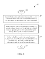
- FIG. 3 is a flowchart of a process 30 according to an example of the present invention.
- the process 30 is utilized in a communication device shown in Fig. 1 , for performing a random access (RA) procedure.
- the process 30 may be compiled into the program code 214 and includes the following steps:
- the communication device first receives first system information transmitted in a first subband resource of at least one subband resource by the network when performing a cell search procedure. Then, the communication device receives second system information transmitted in a second subband resource of the at least one subband resource according to the first system information, after performing the cell search procedure.
- the communication device can perform the RA procedure by using the second subband resource of the at least one subband resource according to at least one of the first system information and the second system information. That is, after performing the cell search procedure, the communication device can use a different subband resource for performing the RA procedure, to avoid that all communication devices use the same subband resource for performing the RA procedure. From another point of view, for each of the communication devices shown in Fig.
- the network can configure the first system information, to control the communication devices to perform the RA procedure by using various subband resources, so as to distribute (i.e., separate) the communication devices over available physical resource.
- the second system information may not be needed, if information for indicating the second subband resource and for performing the RA procedure can be provided completely in the first system information. Otherwise, the first system information and the second system information are both needed to provide the complete information. As a result, collision probability of RA related signalings can be reduced. Resource for repeating the RA procedure can be saved.
- a target of the process 30 is that the communication devices use various subband resources for performing the RA procedure, to reduce collision probability of RA related signalings, so as to save resource for repeating the RA procedure. Realization of the process 30 is not limited.
- Fig. 4 is a schematic diagram of resource allocation according to an example of the present invention.
- physical resource managed by the network is divided into 6 subband resources SR1-SR6, wherein each of the subband resources SR1-SR6 may include one or more resource blocks (RBs) within a corresponding subband.
- the rest of the physical resource is not considered for simplicity.
- 5 communication devices CD1-CD5 all perform the cell search procedure and the RA procedure during time periods TP1-TP2, respectively.
- the communication devices CD1-CD5 can receive system information SI1 transmitted in the subband resource SR6 during the time period TP1.
- each of the communication devices CD1-CD5 can then obtain system information SI2 during the time period TP2 according to the system information SI1.
- the system information SI1 may include information indicating each of the communication devices CD1-CD5 where to receive the system information SI2 and/or information for performing the RA procedure, and is not limited herein.
- the communication device CD1 can receive the system information SI2 transmitted in the subband resource SR1 according to the system information SI1. Then, the communication device CD1 can perform the RA procedure according at least one of the system information SI1 and the system information SI2.
- the system information SI2 may not be needed, if information for indicating the subband resource SR1 and for performing the RA procedure can be provided completely in the system information SI1. Otherwise, the system information SI1 and the system information SI2 are both needed to provide complete information.
- the system information SI1 and the system information SI2 comprise at least one of a carrier frequency of the second subband resource, a bandwidth of the second subband resource, types of applications supported in the second subband resource, antenna information, EAB (extended access barring) information, a physical random access channel (PRACH) resource configuration, a physical downlink shared channel (PDSCH) resource configuration, a physical downlink control channel (PDCCH) resource configuration, a physical uplink shared channel (PUSCH) resource configuration and a physical uplink control channel (PUCCH) resource configuration. That is, part of the channels and parameters can be included in the system information SI1, and the rest is included in the system information SI2.
- PRACH physical random access channel
- PDSCH physical downlink shared channel
- PDCCH physical downlink control channel
- PUSCH physical uplink shared channel
- PUCCH physical uplink control channel
- the communication devices CD2-CD5 can receive the system information SI2 transmitted in the subband resources SR2-SR5 during the time period TP2, respectively, according to the system information SI1. Then, the communication devices CD2-CD5 can perform the RA procedure according at least one of the system information SI1 and the system information SI2. Note that information in the system information SI2 transmitted in different subband resources may not be the same. Besides, a bandwidth of each of the subband resources SR1-SR5 is 1.4MHz and a bandwidth of the physical resource is 20MHz, as shown in Fig. 4 . However, the bandwidth of the subband resource can be 3MHz, 5MHz, 10MHz or 20NHz, and is not limited.
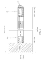
- Fig. 5 is a schematic diagram of a subframe in the subband resource SR6 (during the time period TP1) according to an example of the present invention.
- the subband resource SR6 in the subframe e.g., the subframe #0
- PBCH physical broadcast channel
- PSS primary synchronization signal
- SSS secondary synchronization signal
- UE legacy user equipment
- OFDM orthogonal frequency division multiplexing
- a number of the OFDM symbols used for transmitting the system information SI1 can be fixed. For example, the last few OFDM symbols, e.g., 2 (i.e., OFDM symbols OSB4-5), 3 (i.e., OFDM symbols OSB3-5), etc., are reserved and used for transmitting the system information SI1. Alternatively, the number of the OFDM symbols used for transmitting the system information SI1 can be varied (e.g., according to a signaling transmitted by the network).
- the OFDM symbols in the subframe except those used for the control region and the PBCH are used for transmitting the system information SI1.
- the SSS and the PSS are placed at (i.e., transmitted via) the sixth OFDM symbol and the seventh OFDM symbol, respectively, in the subframe as shown in Fig. 5 , when the wireless communication system is a frequency-division duplexing (FDD) system.
- FDD frequency-division duplexing
- TDD time-division duplexing
- the PSS is placed at (i.e., transmitted via) another subframe, i.e., one more OFDM symbol can be used for transmitting the system information SI1.
- TDD time-division duplexing
- the second subband resource is not in a maximum bandwidth supported by a communication device, e.g., the maximum bandwidth supported by the communication device is not large enough to cover a bandwidth of the second subband resource.
- the communication device cannot easily (or completely) receive system information in another subband resource different from which the communication device currently camps on.
- the communication device CD1 may need to switch a carrier frequency of the communication device CD1 from a carrier frequency of the subband resource SR6 to a carrier frequency of the subband resource SR1 according to the system information SI1, before receiving the system information SI2.
- the communication device CD1 needs to switch the carrier frequency due to that the system information SI2 for the communication device CD1 is transmitted in the subband resource SR1 and the communication device CD1 is unable to receive the system information SI2 in the subband resource SR1 when it camps on the subband resource SR6.
- the system information SI2 for the communication device CD1 is still transmitted in the subband resource SR6, i.e., the communication device CD1 is going to perform the RA procedure by using the subband resource SR6, the communication device CD1 does not need to switch the carrier frequency.
- the maximum bandwidth supported by the communication device CD3 may be large enough to cover the bandwidths of the subband resource SR3 and the subband resource SR6. In this situation, the communication device CD3 does not need to switch the carrier frequency to receive the system information SI2, even the carrier frequencies of the subband resource SR3 and the subband resource SR6 are different.
- the communication device CD1 can perform the RA procedure by using another subband resource (e.g., the subband resource SR3), to increase a possibility of performing the RA procedure successfully.
- a criterion according to which the communication device CD1 decides to use another subband resource for performing the RA procedure is not limited.
- the communication device CD1 can decide to use another subband resource, when the RA procedure is not performed successfully by using the subband resource SR1 for a predetermined amount of times (e.g., a predetermined amount of RA failures).
- the communication device CD1 can decide to use another subband resource, when the RA procedure is not performed successfully by using the subband resource SR1 within a predetermined time interval.
- the communication device CD1 can decide to use another subband resource, when the communication device CD1 receives a signaling (e.g., an extended access barring (EAB) signaling) in the subband resource SR1 indicating that the subband resource SR1 is congested (i.e., crowded).
- a signaling e.g., an extended access barring (EAB) signaling
- a criterion according to which the communication device CD1 selects another subband resource for performing the RA procedure is not limited.
- the communication device can select another subband resource according to a random selection, i.e., randomly select a (different) subband resource.
- the another subband resource is not in a maximum bandwidth supported by a communication device, e.g., the maximum bandwidth supported by the communication device is not large enough to cover a bandwidth of the another subband resource.
- the communication device CD1 may need to switch the carrier frequency of the communication device CD1 from the carrier frequency of the subband resource SR1 to a carrier frequency of another subband resource (e.g., the subband resource SR3), before performing the RA procedure.
- a carrier frequency of another subband resource e.g., the subband resource SR3
- the above description is about a method of performing a RA procedure, and can be summarized into a process 60 as shown in Fig. 6 .
- the process 60 is utilized in a communication device shown in Fig. 1 , and includes the following steps:
- the process 60 is used to illustrate operations of the communication device capable of reducing collision probability of RA related signalings when performing the RA procedure. Detail of the process 60 can be referred to the above illustration, and is not narrated herein.
- Fig. 7 is a flowchart of a process 70 according to an example of the present invention.
- the process 70 is utilized in a communication device shown in Fig. 1 , for performing MTC with the network.
- the process 70 may be compiled into the program code 214 and includes the following steps:
- the communication device first performs a first MTC with the network by using a first subband resource of at least one subband resource. Then, the communication device performs a second MTC with the network by using a second subband resource of the at least one subband resource, after performing the first MTC.
- the communication device does not need to perform MTCs by using the same subband resource, but can perform the MTCs by using various (e.g., different) subband resources.
- the subband resources can be exploited flexibly, and congestion occurred in a specific subband resource can be avoided.
- a target of the process 70 is that the communication devices use various subband resources for performing MTCs, to exploit the subband resources flexibly, so as to avoid congestion occurred in a specific subband resource. Realization of the process 70 is not limited.
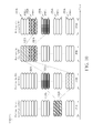
- Fig. 8 is a schematic diagram of resource allocation according to an example of the present invention.
- physical resource managed by the network is divided into 4 subband resources SR1 a-SR4a, wherein each of the subband resources SR1 a-SR4a may include one or more RBs within a corresponding subband.
- the rest of the physical resource is not considered for simplicity.
- 4 communication devices CD1 a-CD4a all perform the cell search procedure and the RA procedure during time periods TP1 a-TP2a, respectively.
- the communication devices CD1 a-CD4a can receive system information SI1 transmitted in the subband resource SR3a during the time period TP1a.
- each of the communication devices CD1 a-CD4a can obtain system information SI2 during the time period TP2a according to the system information SI1.
- the system information SI1 may include information indicating each of the communication devices CD1a-CD4a where to receive the system information SI2 and/or information for performing the RA procedure, and is not limited herein.
- the communication device CD1 a can receive the system information SI2 transmitted in the subband resource SR1 a during the time period TP2a according to the system information SI1. Then, the communication device CD1a can perform the RA procedure according at least one of the system information SI1 and the system information SI2.
- the communication devices CD2a-CD4a can receive the system information SI2 transmitted in the subband resources SR2a-SR4a during the time period TP2a, respectively, according to the system information SI1. Then, the communication devices CD2a-CD4a can perform the RA procedure according at least one of the system information SI1 and the system information SI2.
- the communication devices CD1 a-CD4a After performing the RA procedure, the communication devices CD1 a-CD4a start to perform the MTCs with the network by using the subband resource SR3a during a time period TP3a. In other words, the communication devices CD1 a-CD4a only use various (e.g., different) subband resources for performing the RA procedure, to perform the RA procedure successfully as soon as possible. After performing the RA procedure, the communication devices CD1 a-CD4a reselect the subband resource SR3a, for performing the MTCs with the network.
- the communication devices CD1 a-CD4a can select different subband resources, to perform the MTCs with the network.
- Fig. 9 is a schematic diagram of resource allocation according to an example of the present invention. Different from Fig. 8 , after performing the RA procedure, the communication devices CD1 a-CD4a select different subband resources, for performing the MTCs with the network during the time period TP3a. As shown in Fig. 9 , the communication devices CD1 a-CD2a select the subband resource SR1 a for performing the MTCs with the network, and the communication devices CD3a-CD4a select the subband resource SR2a for performing the MTCs with the network.
- Fig. 10 is a schematic diagram of resource allocation according to an example of the present invention.
- physical resource managed by the network is divided into 5 subband resources SR1b-SR5b, wherein each of the subband resources SR1b-SR5b may include one or more RBs within a corresponding subband.
- the rest of the physical resource is not considered for simplicity.
- 2 communication devices CD1 b-CD2b both perform the cell search procedure and the RA procedure during time periods TP1 b-TP2b, respectively. Detail of performing the cell search procedure and the RA procedure can be referred to the above description, and is not narrated herein.
- the communication devices CD1 b-CD2b both use the subband resource SR4b for performing the cell search procedure during the time period TP1 b. Then, the communication devices CD1 b-CD2b use the subband resource SR3b and the subband resource SR5b for performing the RA procedure during the time period TP2b, respectively. After performing the RA procedure, the communication device CD1 b performs the first MTC and the second MTC with the network by using the subband resource SR1 b (during a time period TP3b) and the subband resource SR2b (during a time period TP4b), respectively.
- the communication device CD2b performs the first MTC and the second MTC with the network by using the subband resource SR2b (during the time period TP3b) and the subband resource SR3b (during the time period TP4b), respectively.
- the communication devices CD1 b-CD2b can exploit the subband resources efficiently and flexibly.
- the second subband resource is not in a maximum bandwidth supported by a communication device, e.g., the maximum bandwidth supported by the communication device is not large enough to cover a bandwidth of the second subband resource.
- the communication device cannot easily or completely receive system information in another subband resource different from which the communication device currently camps on.
- a communication device may need to switch a carrier frequency of the communication device from a carrier frequency of a first subband resource (e.g., the subband resource SR1 b) to a carrier frequency of a second subband resource (e.g., the subband resource SR2b), before performing the MTC (e.g., the second MTC) with the network.
- the communication device needs to switch the carrier frequency due to that the communication device CD1 b is unable to perform the second MTC by using the subband resource SR2b when it camps on the subband resource SR1 b.
- the communication device When the MTC is still performed by using the same subband resource, the communication device does not need to switch the carrier frequency.
- the maximum bandwidth supported by the communication device CD1 b may be large enough to cover the bandwidths of the subband resource SR1b and the subband resource SR2b. In this situation, the communication device CD1 b does not need to switch the carrier frequency, even if the carrier frequencies of the subband resource SR1 b and the subband resource SR2b are different.
- the subband resource mentioned above is preferably referred to activated resources.
- the communication device can switch (with or without changing the carrier frequency) from the first subband resource to the second subband resource according to at least one of a higher layer signaling transmitted by the network, a random selection (performed by the communication device, or performed and transmitted by the network), an application type performed by the communication device, capability of the communication device and a subband configuration transmitted by the network. That is, the network may indicate, configure or assign the communication device, to switch the subband resources semi-statistically or dynamically, according to the abovementioned methods.
- the communication device should reply an acknowledgement corresponding to the higher layer signaling to the network within a predetermined time interval, after receiving the higher layer signaling.
- the communication device may switch the subband resources semi-statistically or dynamically according to the abovementioned causes.
- the above description is about a method of performing MTC, and can be summarized into a process 110 as shown in Fig.11 .
- the process 110 is utilized in a communication device shown in Fig. 1 , and includes the following steps:
- the process 110 is used to illustrate operations of the communication device capable of exploiting the subband resources efficiently and flexibly. Detail of the process 110 can be referred to the above illustration, and is not narrated herein.
- the abovementioned steps of the processes including suggested steps can be realized by means that could be a hardware, a firmware known as a combination of a hardware device and computer instructions and data that reside as read-only software on the hardware device, or an electronic system.
- hardware can include analog, digital and mixed circuits known as microcircuit, microchip, or silicon chip.
- the electronic system can include a system on chip (SOC), system in package (SiP), a computer on module (COM), and the communication device 20.
- SOC system on chip
- SiP system in package
- COM computer on module
- the present invention provides methods for handling resource allocation for a communication device (e.g., a MTC device) capable performing MTC with the network.
- a communication device e.g., a MTC device
- resource e.g., subband resource
- the resource can be exploited efficiently and flexibly according to the present invention.
Landscapes
- Engineering & Computer Science (AREA)
- Computer Networks & Wireless Communication (AREA)
- Signal Processing (AREA)
- Databases & Information Systems (AREA)
- Mobile Radio Communication Systems (AREA)
Applications Claiming Priority (3)
| Application Number | Priority Date | Filing Date | Title |
|---|---|---|---|
| US201161556841P | 2011-11-08 | 2011-11-08 | |
| US201161566019P | 2011-12-02 | 2011-12-02 | |
| US13/671,526 US9131468B2 (en) | 2011-11-08 | 2012-11-07 | Method of handling resource allocation for MTC and related communication device |
Publications (3)
| Publication Number | Publication Date |
|---|---|
| EP2592889A2 true EP2592889A2 (de) | 2013-05-15 |
| EP2592889A3 EP2592889A3 (de) | 2017-01-25 |
| EP2592889B1 EP2592889B1 (de) | 2020-08-12 |
Family
ID=47257468
Family Applications (1)
| Application Number | Title | Priority Date | Filing Date |
|---|---|---|---|
| EP12191744.7A Active EP2592889B1 (de) | 2011-11-08 | 2012-11-08 | Verfahren zur handhabung der ressourcenzuweisung für maschinenartige kommunikation und zugehörige kommunikationsvorrichtung |
Country Status (4)
| Country | Link |
|---|---|
| US (2) | US9131468B2 (de) |
| EP (1) | EP2592889B1 (de) |
| CN (2) | CN103139781B (de) |
| TW (1) | TWI491293B (de) |
Cited By (1)
| Publication number | Priority date | Publication date | Assignee | Title |
|---|---|---|---|---|
| EP2999140A4 (de) * | 2013-05-16 | 2016-12-14 | Lg Electronics Inc | Verfahren zur übertragung eines signals zur verbesserung der abdeckung und vorrichtung dafür |
Families Citing this family (16)
| Publication number | Priority date | Publication date | Assignee | Title |
|---|---|---|---|---|
| CN103327639B (zh) * | 2013-06-20 | 2015-11-11 | 吉林大学 | Lte系统中利用pucch传输m2m业务的方法 |
| CN105340198B (zh) * | 2013-06-26 | 2018-08-14 | Lg电子株式会社 | 在无线通信系统中获取控制信息的方法和设备 |
| US20160242203A1 (en) * | 2013-11-22 | 2016-08-18 | Lg Electronics Inc. | Method for receiving bundle of pdcch, and mtc device |
| JP2017534193A (ja) * | 2014-10-30 | 2017-11-16 | エルジー エレクトロニクス インコーポレイティド | Mtc機器のpucch転送方法 |
| US9602953B2 (en) * | 2014-12-08 | 2017-03-21 | Intel Corporation | Techniques and configurations associated with partitioning of a communication band |
| US10079665B2 (en) | 2015-01-29 | 2018-09-18 | Samsung Electronics Co., Ltd. | System and method for link adaptation for low cost user equipments |
| WO2016186430A1 (ko) * | 2015-05-18 | 2016-11-24 | 주식회사 케이티 | 시스템 정보 송수신 방법 및 그 장치 |
| KR101956978B1 (ko) * | 2015-05-18 | 2019-03-12 | 주식회사 케이티 | 시스템 정보 송수신 방법 및 그 장치 |
| WO2018084777A1 (en) * | 2016-11-04 | 2018-05-11 | Telefonaktiebolaget Lm Ericsson (Publ) | Methods and devices for acquiring system information |
| CN108811094B (zh) * | 2017-05-02 | 2021-08-13 | 普天信息技术有限公司 | 一种数据传输方法 |
| CN111034301B (zh) * | 2017-08-11 | 2023-12-01 | 三星电子株式会社 | 用于支持补充上行链路频率的方法和装置 |
| KR102137311B1 (ko) | 2017-08-18 | 2020-07-24 | 아서스테크 컴퓨터 인코포레이션 | 무선 통신 시스템에서 랜덤 액세스 구성을 위한 방법 및 장치 |
| CN110635878B (zh) * | 2018-06-22 | 2020-09-01 | 维沃移动通信有限公司 | 一种命令处理方法及终端设备 |
| CN112218374B (zh) * | 2019-07-12 | 2025-06-10 | 华为技术有限公司 | 一种通信方法、通信装置、终端设备及网络设备 |
| WO2022044558A1 (ja) * | 2020-08-28 | 2022-03-03 | 株式会社Nttドコモ | 端末、基地局及び通信方法 |
| CN114980271B (zh) * | 2022-05-20 | 2025-09-23 | 维沃移动通信有限公司 | 小区注册方法及终端 |
Family Cites Families (33)
| Publication number | Priority date | Publication date | Assignee | Title |
|---|---|---|---|---|
| DE102004027350B4 (de) * | 2004-06-01 | 2006-07-27 | Siemens Ag | Verfahren zur Einbuchung eines Funkmoduls in ein zellulares Funknetz |
| CN101300886B (zh) * | 2005-11-04 | 2012-06-13 | 株式会社Ntt都科摩 | 传输控制方法、移动台以及无线基站 |
| DE602005019434D1 (de) * | 2005-12-13 | 2010-04-01 | Panasonic Corp | Zuordnung von Broadcast System Informationen zu Transportkanälen in einem mobilen Kommunikationssystem |
| US8059728B2 (en) * | 2006-02-11 | 2011-11-15 | Samsung Electronics Co., Ltd | Method and apparatus for transmitting/receiving broadcast channels in cellular communication systems supporting scalable bandwidth |
| KR101258130B1 (ko) * | 2006-08-09 | 2013-04-25 | 미쓰비시덴키 가부시키가이샤 | 데이터 통신방법 및 이동체 통신 시스템 |
| US8509323B2 (en) | 2006-08-22 | 2013-08-13 | Motorola Mobility Llc | Resource allocation including a DC sub-carrier in a wireless communication system |
| JP5052377B2 (ja) * | 2007-06-19 | 2012-10-17 | パナソニック株式会社 | 無線通信基地局装置、無線通信端末装置及びギャップ生成方法 |
| US8441951B2 (en) * | 2008-01-30 | 2013-05-14 | Telefonatiebolaget Lm Ericsson (Publ) | Configuration measurement time slots for mobile terminals in a TDD system |
| KR101636089B1 (ko) | 2008-04-21 | 2016-07-04 | 애플 인크. | Harq 프로토콜을 위한 방법 및 시스템 |
| GB2459504B (en) | 2008-04-25 | 2010-06-16 | Ipwireless Inc | Wireless communication unit and method for channel estimation |
| CN102176790B (zh) * | 2008-04-28 | 2014-01-01 | 富士通株式会社 | 无线通信系统中的连接处理方法、无线基站以及无线终端 |
| RU2476001C2 (ru) * | 2008-04-28 | 2013-02-20 | Фудзицу Лимитед | Способ обработки соединения в системе беспроводной связи, и базовая станция беспроводной связи и терминал беспроводной связи |
| JP5168015B2 (ja) | 2008-07-31 | 2013-03-21 | 富士通モバイルコミュニケーションズ株式会社 | 無線基地局装置および移動無線端末装置 |
| EP2312897B1 (de) * | 2008-08-06 | 2018-10-10 | Sharp Kabushiki Kaisha | Mobilstationsvorrichtung, basisstationsvorrichtung und kommunikationsverfahren |
| KR101478028B1 (ko) * | 2008-09-23 | 2014-12-31 | 삼성전자주식회사 | 확장성 대역폭을 지원하는 셀룰러 무선통신시스템을 위한 하향링크채널의 송수신 방법 및 장치 |
| KR101611271B1 (ko) * | 2008-10-29 | 2016-04-26 | 엘지전자 주식회사 | 다중 반송파 결합 환경에서의 업링크 임의 접속 방법 |
| US8228862B2 (en) | 2008-12-03 | 2012-07-24 | Samsung Electronics Co., Ltd. | Method and system for reference signal pattern design |
| CN101771646A (zh) | 2009-01-07 | 2010-07-07 | 中兴通讯股份有限公司 | 控制信道的资源映射方法 |
| AU2010222296B2 (en) * | 2009-03-13 | 2014-03-20 | Sharp Kabushiki Kaisha | Mobile station apparatus, base station apparatus, integrated circuit, and method of detecting random access problems |
| CN101860956B (zh) * | 2009-04-10 | 2013-09-25 | 电信科学技术研究院 | 一种在多载波系统中触发调度信息上报的方法和装置 |
| KR101616605B1 (ko) * | 2009-04-23 | 2016-04-28 | 인터디지탈 패튼 홀딩스, 인크 | 멀티캐리어 무선 통신에서의 임의 접속을 위한 방법 및 장치 |
| US20110128919A1 (en) * | 2009-11-30 | 2011-06-02 | Samsung Electronics Co. Ltd. | Device and method for selecting transceiver in mobile communication system |
| KR101382161B1 (ko) | 2010-02-12 | 2014-04-07 | 알까뗄 루슨트 | 머신형 통신을 위한 네트워크 액세스 방법 및 시스템 |
| EP2554008B1 (de) * | 2010-04-01 | 2020-02-19 | Samsung Electronics Co., Ltd | Erweiterter zufalls-zugriffsmechanismus in einem drahtlosen kommunikationssystem |
| US9185530B2 (en) * | 2010-04-02 | 2015-11-10 | Interdigital Patent Holdings, Inc. | Group procedures for machine type communication devices |
| US8929306B2 (en) * | 2010-05-26 | 2015-01-06 | Lg Electronics Inc. | NAS-based signaling protocol for overload protection of random access in massive machine type communication |
| US20110310854A1 (en) * | 2010-06-17 | 2011-12-22 | Jialin Zou | Method of determining access times for wireless communication devices |
| US8831119B2 (en) | 2010-06-28 | 2014-09-09 | Lg Electronics Inc. | Method and apparatus for transmitting synchronization signal in multi-node system |
| DK2622929T3 (en) * | 2010-10-01 | 2015-04-20 | Ericsson Telefon Ab L M | Mobile terminal, base station and methods therein |
| US9107118B2 (en) * | 2010-10-21 | 2015-08-11 | Google Technology Holdings LLC | Method for signaling a mobile wireless device to switch to a preset carrier in a multi-carrier 4G network |
| US9408231B2 (en) * | 2011-05-09 | 2016-08-02 | Nokia Solutions And Networks Oy | Extended access barring mechanisms for machine type communications |
| CN102164421B (zh) * | 2011-05-12 | 2013-11-20 | 大唐移动通信设备有限公司 | 一种随机接入的方法及其系统和mtc设备 |
| US8830828B2 (en) * | 2011-05-31 | 2014-09-09 | Innovative Sonic Corporation | Method and apparatus to prevent RAN (radio access network) overload for legacy networks in a wireless communication system |
-
2012
- 2012-11-07 US US13/671,526 patent/US9131468B2/en active Active
- 2012-11-08 CN CN201210444059.0A patent/CN103139781B/zh active Active
- 2012-11-08 EP EP12191744.7A patent/EP2592889B1/de active Active
- 2012-11-08 TW TW101141619A patent/TWI491293B/zh active
- 2012-11-08 CN CN201510506007.5A patent/CN105163264B/zh active Active
-
2015
- 2015-07-24 US US14/807,897 patent/US10091605B2/en active Active
Non-Patent Citations (1)
| Title |
|---|
| None |
Cited By (4)
| Publication number | Priority date | Publication date | Assignee | Title |
|---|---|---|---|---|
| EP2999140A4 (de) * | 2013-05-16 | 2016-12-14 | Lg Electronics Inc | Verfahren zur übertragung eines signals zur verbesserung der abdeckung und vorrichtung dafür |
| US9913268B2 (en) | 2013-05-16 | 2018-03-06 | Lg Electronics Inc. | Signal transmission method for coverage improvement and apparatus for same |
| US9974068B2 (en) | 2013-05-16 | 2018-05-15 | Lg Electronics Inc. | Method for transmitting signal for improving coverage and apparatus for same |
| US10477535B2 (en) | 2013-05-16 | 2019-11-12 | Lg Electronics Inc. | Method for transmitting signal for improving coverage and apparatus for same |
Also Published As
| Publication number | Publication date |
|---|---|
| CN105163264A (zh) | 2015-12-16 |
| CN103139781A (zh) | 2013-06-05 |
| US20130114537A1 (en) | 2013-05-09 |
| US10091605B2 (en) | 2018-10-02 |
| US20150334510A1 (en) | 2015-11-19 |
| US9131468B2 (en) | 2015-09-08 |
| EP2592889A3 (de) | 2017-01-25 |
| EP2592889B1 (de) | 2020-08-12 |
| CN103139781B (zh) | 2016-05-25 |
| CN105163264B (zh) | 2019-04-09 |
| TWI491293B (zh) | 2015-07-01 |
| TW201320801A (zh) | 2013-05-16 |
Similar Documents
| Publication | Publication Date | Title |
|---|---|---|
| EP2592889B1 (de) | Verfahren zur handhabung der ressourcenzuweisung für maschinenartige kommunikation und zugehörige kommunikationsvorrichtung | |
| EP2922366B1 (de) | Verfahren zur handhabung von vorrichtung-zu-vorrichtung-betrieb | |
| EP3236704B1 (de) | Vorrichtung und verfahren zur handhabung einer vorrichtung-zu-vorrichtung-kommunikation | |
| EP2429239A2 (de) | Verfahren zur Konfiguration sekundärer Zellen und zugehörige Kommunikationsvorrichtung | |
| EP2373111B1 (de) | Verfahren zur Änderung des primären Komponententrägers und zugehörige Kommunikationsvorrichtung | |
| US9774427B2 (en) | Method of handling uplink/downlink configurations for time-division duplexing system and related communication device | |
| EP2750456A1 (de) | Verfahren zur Durchführung der Zellenauswahl in einem Funkabdeckungsverbesserungsmodus und dazugehörige Kommunikationsvorrichtung | |
| US9882699B2 (en) | Device and method of handling device-to-cellular communication | |
| US11240842B2 (en) | Device and method of handling transmission/reception for serving cell | |
| US9320057B2 (en) | Method and apparatus for performing machine-type communication device access in wireless communication system | |
| US20250261191A1 (en) | Device of Handling PUSCH Transmissions | |
| US9191973B2 (en) | Method of handling random access channel procedure and related communication device | |
| EP2903382B1 (de) | Verfahren zur handhabung eines vorrichtung-zu-vorrichtung-signals und eines vorrichtung-zu-zelle-signals | |
| US20190082480A1 (en) | Device and Method of Handling a Radio Resource Control Connection | |
| EP2675100A2 (de) | Verfahren zur Anzeige eines Downlink-Steuerkanals und Kommunikationsvorrichtung dafür | |
| EP3220708A1 (de) | Vorrichtung und verfahren zur handhabung der übertragung in nichtlizenziertem band | |
| US9860805B2 (en) | Device of handling energy detection in unlicensed band | |
| EP2922359A2 (de) | Verfahren zur handhabung eines downlink-only-trägers und zugehörige kommunikationsvorrichtung | |
| US10085241B2 (en) | Device of reporting control information |
Legal Events
| Date | Code | Title | Description |
|---|---|---|---|
| PUAI | Public reference made under article 153(3) epc to a published international application that has entered the european phase |
Free format text: ORIGINAL CODE: 0009012 |
|
| AK | Designated contracting states |
Kind code of ref document: A2 Designated state(s): AL AT BE BG CH CY CZ DE DK EE ES FI FR GB GR HR HU IE IS IT LI LT LU LV MC MK MT NL NO PL PT RO RS SE SI SK SM TR |
|
| AX | Request for extension of the european patent |
Extension state: BA ME |
|
| PUAL | Search report despatched |
Free format text: ORIGINAL CODE: 0009013 |
|
| AK | Designated contracting states |
Kind code of ref document: A3 Designated state(s): AL AT BE BG CH CY CZ DE DK EE ES FI FR GB GR HR HU IE IS IT LI LT LU LV MC MK MT NL NO PL PT RO RS SE SI SK SM TR |
|
| AX | Request for extension of the european patent |
Extension state: BA ME |
|
| RIC1 | Information provided on ipc code assigned before grant |
Ipc: H04W 74/00 20090101AFI20161219BHEP Ipc: H04W 4/00 20090101ALI20161219BHEP |
|
| STAA | Information on the status of an ep patent application or granted ep patent |
Free format text: STATUS: REQUEST FOR EXAMINATION WAS MADE |
|
| 17P | Request for examination filed |
Effective date: 20170724 |
|
| RBV | Designated contracting states (corrected) |
Designated state(s): AL AT BE BG CH CY CZ DE DK EE ES FI FR GB GR HR HU IE IS IT LI LT LU LV MC MK MT NL NO PL PT RO RS SE SI SK SM TR |
|
| STAA | Information on the status of an ep patent application or granted ep patent |
Free format text: STATUS: EXAMINATION IS IN PROGRESS |
|
| 17Q | First examination report despatched |
Effective date: 20180117 |
|
| RAP1 | Party data changed (applicant data changed or rights of an application transferred) |
Owner name: ACER INCORPORATED |
|
| GRAP | Despatch of communication of intention to grant a patent |
Free format text: ORIGINAL CODE: EPIDOSNIGR1 |
|
| STAA | Information on the status of an ep patent application or granted ep patent |
Free format text: STATUS: GRANT OF PATENT IS INTENDED |
|
| RIC1 | Information provided on ipc code assigned before grant |
Ipc: H04W 74/08 20090101ALI20200225BHEP Ipc: H04W 74/00 20090101AFI20200225BHEP Ipc: H04W 4/70 20180101ALI20200225BHEP |
|
| INTG | Intention to grant announced |
Effective date: 20200313 |
|
| GRAS | Grant fee paid |
Free format text: ORIGINAL CODE: EPIDOSNIGR3 |
|
| GRAA | (expected) grant |
Free format text: ORIGINAL CODE: 0009210 |
|
| STAA | Information on the status of an ep patent application or granted ep patent |
Free format text: STATUS: THE PATENT HAS BEEN GRANTED |
|
| AK | Designated contracting states |
Kind code of ref document: B1 Designated state(s): AL AT BE BG CH CY CZ DE DK EE ES FI FR GB GR HR HU IE IS IT LI LT LU LV MC MK MT NL NO PL PT RO RS SE SI SK SM TR |
|
| REG | Reference to a national code |
Ref country code: GB Ref legal event code: FG4D |
|
| REG | Reference to a national code |
Ref country code: CH Ref legal event code: EP |
|
| REG | Reference to a national code |
Ref country code: DE Ref legal event code: R096 Ref document number: 602012071732 Country of ref document: DE |
|
| REG | Reference to a national code |
Ref country code: IE Ref legal event code: FG4D |
|
| REG | Reference to a national code |
Ref country code: AT Ref legal event code: REF Ref document number: 1302850 Country of ref document: AT Kind code of ref document: T Effective date: 20200915 |
|
| REG | Reference to a national code |
Ref country code: NL Ref legal event code: FP |
|
| REG | Reference to a national code |
Ref country code: LT Ref legal event code: MG4D |
|
| PG25 | Lapsed in a contracting state [announced via postgrant information from national office to epo] |
Ref country code: LT Free format text: LAPSE BECAUSE OF FAILURE TO SUBMIT A TRANSLATION OF THE DESCRIPTION OR TO PAY THE FEE WITHIN THE PRESCRIBED TIME-LIMIT Effective date: 20200812 Ref country code: HR Free format text: LAPSE BECAUSE OF FAILURE TO SUBMIT A TRANSLATION OF THE DESCRIPTION OR TO PAY THE FEE WITHIN THE PRESCRIBED TIME-LIMIT Effective date: 20200812 Ref country code: NO Free format text: LAPSE BECAUSE OF FAILURE TO SUBMIT A TRANSLATION OF THE DESCRIPTION OR TO PAY THE FEE WITHIN THE PRESCRIBED TIME-LIMIT Effective date: 20201112 Ref country code: BG Free format text: LAPSE BECAUSE OF FAILURE TO SUBMIT A TRANSLATION OF THE DESCRIPTION OR TO PAY THE FEE WITHIN THE PRESCRIBED TIME-LIMIT Effective date: 20201112 Ref country code: ES Free format text: LAPSE BECAUSE OF FAILURE TO SUBMIT A TRANSLATION OF THE DESCRIPTION OR TO PAY THE FEE WITHIN THE PRESCRIBED TIME-LIMIT Effective date: 20200812 Ref country code: GR Free format text: LAPSE BECAUSE OF FAILURE TO SUBMIT A TRANSLATION OF THE DESCRIPTION OR TO PAY THE FEE WITHIN THE PRESCRIBED TIME-LIMIT Effective date: 20201113 Ref country code: FI Free format text: LAPSE BECAUSE OF FAILURE TO SUBMIT A TRANSLATION OF THE DESCRIPTION OR TO PAY THE FEE WITHIN THE PRESCRIBED TIME-LIMIT Effective date: 20200812 Ref country code: SE Free format text: LAPSE BECAUSE OF FAILURE TO SUBMIT A TRANSLATION OF THE DESCRIPTION OR TO PAY THE FEE WITHIN THE PRESCRIBED TIME-LIMIT Effective date: 20200812 |
|
| REG | Reference to a national code |
Ref country code: AT Ref legal event code: MK05 Ref document number: 1302850 Country of ref document: AT Kind code of ref document: T Effective date: 20200812 |
|
| PG25 | Lapsed in a contracting state [announced via postgrant information from national office to epo] |
Ref country code: RS Free format text: LAPSE BECAUSE OF FAILURE TO SUBMIT A TRANSLATION OF THE DESCRIPTION OR TO PAY THE FEE WITHIN THE PRESCRIBED TIME-LIMIT Effective date: 20200812 Ref country code: PL Free format text: LAPSE BECAUSE OF FAILURE TO SUBMIT A TRANSLATION OF THE DESCRIPTION OR TO PAY THE FEE WITHIN THE PRESCRIBED TIME-LIMIT Effective date: 20200812 Ref country code: LV Free format text: LAPSE BECAUSE OF FAILURE TO SUBMIT A TRANSLATION OF THE DESCRIPTION OR TO PAY THE FEE WITHIN THE PRESCRIBED TIME-LIMIT Effective date: 20200812 Ref country code: IS Free format text: LAPSE BECAUSE OF FAILURE TO SUBMIT A TRANSLATION OF THE DESCRIPTION OR TO PAY THE FEE WITHIN THE PRESCRIBED TIME-LIMIT Effective date: 20201212 |
|
| PG25 | Lapsed in a contracting state [announced via postgrant information from national office to epo] |
Ref country code: SM Free format text: LAPSE BECAUSE OF FAILURE TO SUBMIT A TRANSLATION OF THE DESCRIPTION OR TO PAY THE FEE WITHIN THE PRESCRIBED TIME-LIMIT Effective date: 20200812 Ref country code: RO Free format text: LAPSE BECAUSE OF FAILURE TO SUBMIT A TRANSLATION OF THE DESCRIPTION OR TO PAY THE FEE WITHIN THE PRESCRIBED TIME-LIMIT Effective date: 20200812 Ref country code: DK Free format text: LAPSE BECAUSE OF FAILURE TO SUBMIT A TRANSLATION OF THE DESCRIPTION OR TO PAY THE FEE WITHIN THE PRESCRIBED TIME-LIMIT Effective date: 20200812 Ref country code: EE Free format text: LAPSE BECAUSE OF FAILURE TO SUBMIT A TRANSLATION OF THE DESCRIPTION OR TO PAY THE FEE WITHIN THE PRESCRIBED TIME-LIMIT Effective date: 20200812 Ref country code: CZ Free format text: LAPSE BECAUSE OF FAILURE TO SUBMIT A TRANSLATION OF THE DESCRIPTION OR TO PAY THE FEE WITHIN THE PRESCRIBED TIME-LIMIT Effective date: 20200812 |
|
| REG | Reference to a national code |
Ref country code: DE Ref legal event code: R097 Ref document number: 602012071732 Country of ref document: DE |
|
| PG25 | Lapsed in a contracting state [announced via postgrant information from national office to epo] |
Ref country code: AT Free format text: LAPSE BECAUSE OF FAILURE TO SUBMIT A TRANSLATION OF THE DESCRIPTION OR TO PAY THE FEE WITHIN THE PRESCRIBED TIME-LIMIT Effective date: 20200812 Ref country code: AL Free format text: LAPSE BECAUSE OF FAILURE TO SUBMIT A TRANSLATION OF THE DESCRIPTION OR TO PAY THE FEE WITHIN THE PRESCRIBED TIME-LIMIT Effective date: 20200812 |
|
| PLBE | No opposition filed within time limit |
Free format text: ORIGINAL CODE: 0009261 |
|
| STAA | Information on the status of an ep patent application or granted ep patent |
Free format text: STATUS: NO OPPOSITION FILED WITHIN TIME LIMIT |
|
| PG25 | Lapsed in a contracting state [announced via postgrant information from national office to epo] |
Ref country code: MC Free format text: LAPSE BECAUSE OF FAILURE TO SUBMIT A TRANSLATION OF THE DESCRIPTION OR TO PAY THE FEE WITHIN THE PRESCRIBED TIME-LIMIT Effective date: 20200812 Ref country code: SK Free format text: LAPSE BECAUSE OF FAILURE TO SUBMIT A TRANSLATION OF THE DESCRIPTION OR TO PAY THE FEE WITHIN THE PRESCRIBED TIME-LIMIT Effective date: 20200812 |
|
| REG | Reference to a national code |
Ref country code: CH Ref legal event code: PL |
|
| 26N | No opposition filed |
Effective date: 20210514 |
|
| PG25 | Lapsed in a contracting state [announced via postgrant information from national office to epo] |
Ref country code: LU Free format text: LAPSE BECAUSE OF NON-PAYMENT OF DUE FEES Effective date: 20201108 |
|
| REG | Reference to a national code |
Ref country code: BE Ref legal event code: MM Effective date: 20201130 |
|
| PG25 | Lapsed in a contracting state [announced via postgrant information from national office to epo] |
Ref country code: CH Free format text: LAPSE BECAUSE OF NON-PAYMENT OF DUE FEES Effective date: 20201130 Ref country code: LI Free format text: LAPSE BECAUSE OF NON-PAYMENT OF DUE FEES Effective date: 20201130 Ref country code: SI Free format text: LAPSE BECAUSE OF FAILURE TO SUBMIT A TRANSLATION OF THE DESCRIPTION OR TO PAY THE FEE WITHIN THE PRESCRIBED TIME-LIMIT Effective date: 20200812 |
|
| PG25 | Lapsed in a contracting state [announced via postgrant information from national office to epo] |
Ref country code: IE Free format text: LAPSE BECAUSE OF NON-PAYMENT OF DUE FEES Effective date: 20201108 |
|
| PG25 | Lapsed in a contracting state [announced via postgrant information from national office to epo] |
Ref country code: TR Free format text: LAPSE BECAUSE OF FAILURE TO SUBMIT A TRANSLATION OF THE DESCRIPTION OR TO PAY THE FEE WITHIN THE PRESCRIBED TIME-LIMIT Effective date: 20200812 Ref country code: MT Free format text: LAPSE BECAUSE OF FAILURE TO SUBMIT A TRANSLATION OF THE DESCRIPTION OR TO PAY THE FEE WITHIN THE PRESCRIBED TIME-LIMIT Effective date: 20200812 Ref country code: CY Free format text: LAPSE BECAUSE OF FAILURE TO SUBMIT A TRANSLATION OF THE DESCRIPTION OR TO PAY THE FEE WITHIN THE PRESCRIBED TIME-LIMIT Effective date: 20200812 |
|
| PG25 | Lapsed in a contracting state [announced via postgrant information from national office to epo] |
Ref country code: MK Free format text: LAPSE BECAUSE OF FAILURE TO SUBMIT A TRANSLATION OF THE DESCRIPTION OR TO PAY THE FEE WITHIN THE PRESCRIBED TIME-LIMIT Effective date: 20200812 |
|
| PG25 | Lapsed in a contracting state [announced via postgrant information from national office to epo] |
Ref country code: PT Free format text: LAPSE BECAUSE OF FAILURE TO SUBMIT A TRANSLATION OF THE DESCRIPTION OR TO PAY THE FEE WITHIN THE PRESCRIBED TIME-LIMIT Effective date: 20200812 Ref country code: BE Free format text: LAPSE BECAUSE OF NON-PAYMENT OF DUE FEES Effective date: 20201130 |
|
| REG | Reference to a national code |
Ref country code: DE Ref legal event code: R082 Ref document number: 602012071732 Country of ref document: DE Representative=s name: STRAUS, ALEXANDER, DIPL.-CHEM.UNIV. DR.PHIL., DE |
|
| PGFP | Annual fee paid to national office [announced via postgrant information from national office to epo] |
Ref country code: GB Payment date: 20250925 Year of fee payment: 14 |
|
| PGFP | Annual fee paid to national office [announced via postgrant information from national office to epo] |
Ref country code: FR Payment date: 20250930 Year of fee payment: 14 |
|
| PGFP | Annual fee paid to national office [announced via postgrant information from national office to epo] |
Ref country code: NL Payment date: 20251003 Year of fee payment: 14 |
|
| PGFP | Annual fee paid to national office [announced via postgrant information from national office to epo] |
Ref country code: DE Payment date: 20250930 Year of fee payment: 14 |
|
| PGFP | Annual fee paid to national office [announced via postgrant information from national office to epo] |
Ref country code: IT Payment date: 20251022 Year of fee payment: 14 |