EP2592768A1 - Photonic system and method for tunable beamforming of the electric field radiated by a phased array antenna - Google Patents
Photonic system and method for tunable beamforming of the electric field radiated by a phased array antenna Download PDFInfo
- Publication number
- EP2592768A1 EP2592768A1 EP10809198.4A EP10809198A EP2592768A1 EP 2592768 A1 EP2592768 A1 EP 2592768A1 EP 10809198 A EP10809198 A EP 10809198A EP 2592768 A1 EP2592768 A1 EP 2592768A1
- Authority
- EP
- European Patent Office
- Prior art keywords
- optic
- polarization
- electric field
- beamforming
- phased array
- Prior art date
- Legal status (The legal status is an assumption and is not a legal conclusion. Google has not performed a legal analysis and makes no representation as to the accuracy of the status listed.)
- Granted
Links
Images


Classifications
-
- H—ELECTRICITY
- H01—ELECTRIC ELEMENTS
- H01Q—ANTENNAS, i.e. RADIO AERIALS
- H01Q3/00—Arrangements for changing or varying the orientation or the shape of the directional pattern of the waves radiated from an antenna or antenna system
- H01Q3/26—Arrangements for changing or varying the orientation or the shape of the directional pattern of the waves radiated from an antenna or antenna system varying the relative phase or relative amplitude of energisation between two or more active radiating elements; varying the distribution of energy across a radiating aperture
- H01Q3/2682—Time delay steered arrays
-
- H—ELECTRICITY
- H01—ELECTRIC ELEMENTS
- H01Q—ANTENNAS, i.e. RADIO AERIALS
- H01Q3/00—Arrangements for changing or varying the orientation or the shape of the directional pattern of the waves radiated from an antenna or antenna system
- H01Q3/26—Arrangements for changing or varying the orientation or the shape of the directional pattern of the waves radiated from an antenna or antenna system varying the relative phase or relative amplitude of energisation between two or more active radiating elements; varying the distribution of energy across a radiating aperture
- H01Q3/2676—Optically controlled phased array
-
- H—ELECTRICITY
- H04—ELECTRIC COMMUNICATION TECHNIQUE
- H04B—TRANSMISSION
- H04B10/00—Transmission systems employing electromagnetic waves other than radio-waves, e.g. infrared, visible or ultraviolet light, or employing corpuscular radiation, e.g. quantum communication
- H04B10/25—Arrangements specific to fibre transmission
- H04B10/2575—Radio-over-fibre, e.g. radio frequency signal modulated onto an optical carrier
- H04B10/25752—Optical arrangements for wireless networks
-
- H—ELECTRICITY
- H04—ELECTRIC COMMUNICATION TECHNIQUE
- H04B—TRANSMISSION
- H04B2210/00—Indexing scheme relating to optical transmission systems
- H04B2210/006—Devices for generating or processing an RF signal by optical means
Definitions
- This invention discloses a photonic system and method with the purpose of beamforming the electric field yield by a phased array antenna (PAA).
- PAA phased array antenna
- the system relies on a photonic tunable optical delay line (TODL), which is an Mach-Zehnder optical interferometer with a predefined differential time delay between arms. The time delay is tuned by adjusting the coupling ratio between the power applied to each one of the interferometer's delay lines.
- TODL photonic tunable optical delay line
- ML monochromatic light
- the proposed invention presents a novel approach in beamforming systems for the electric field radiated by a PAA.
- PAA's are being increasingly used, because such antennas allow directing the radiated beam precisely to any target direction, without using any mechanical displacement. Since the bandwidth of data transmission is growing in wired or wireless communication systems, interconnecting systems between both these types of communication systems are required, which allow high data transmission rates.
- a wireless network system with high data transmission rates ⁇ 1 Gb/s
- RoF radio over fiber
- the PAA will direct the beam in a target direction using the proposed system, since it allows the acceptance of high data transmission rates.
- Another area of interest outside communication systems is radio astronomy, which requires advanced antenna technology to monitor signals arriving from outer space with low power and high bandwidths.
- the proposed system is rather simple and is based on a well-known optics device, the Mach-Zehnder delay interferometer (MZDI). Its implementation is made with commercially available components. It also allows a very fast beam tuning, particularly when its implementation uses integrated optics. According to its inventors point of view, the main advantage is that it just requires one optical delay line (the birefringent medium in the embodiment shown in Fig. 3 ) and a single ML source, independently of the quantity of elementary antennas. This feature was not found in any techniques reported in prior art's literature.
- a PAA comprises N antennas disposed along the three spatial dimensions.
- the antennas which form the PAA are known as elementary antennas.
- a PAA allows the optimization and the beamforming of the radiated electrical field through the adjustment of the amplitude and phase of the radio frequency (RF) signals sent to each elementary antenna. This is an exclusive feature for the PAA's, since in an individual antenna the optimization of the radiated electrical field depends on the antenna's design. In addition, the beamforming of the radiated electrical field depends on the spatial orientation of the antenna.
- the beamforming of the electrical field radiated by the PAA can be controlled through the phase of the RF signals applied to each elementary antenna. More precisely, the PAA can be fed by a single RF signal, which is split to all elementary antennas including a tunable phase shift. Although tunable, the phase shift is constant. This means the induced phase shift value is correct only for a specific RF frequency. In a PAA, this implies that the emitted frequency should be constant. Otherwise, different RF frequencies get different phase shifts, and so the beamforming of the electric field becomes dependent on the emitted frequency. In the case of data transmission over one RF carrier frequency, this implies that the data signal bandwidth should be as low as possible. Since there are many applications with high bandwidth (e.g., RADAR signals, Gb/s wireless networks, radio astronomy, etc.), the beamforming of the radiated electric field cannot be efficiently performed with such a technique.
- high bandwidth e.g., RADAR signals, Gb/s wireless networks, radio astronomy, etc.
- phase shifts that depend on RF frequency.
- a phase shift depending on frequency consists in a time delay line. Therefore, instead of a phase shift, each elementary antenna should include a tunable time delay.
- the electrical implementation of a tunable time delay is particularly challenging at high frequencies, since increasing time delays implies increasing the length of the delay line, which in turn leads to greater insertion losses and a reduction in bandwidth.
- Such disadvantages are overcome using photonic implementations of tunable delay lines.
- the advantages of photonic systems consist on low losses, broad bandwidth, lighter weights, smaller dimensions and immunity to electromagnetic interference.
- a PAA with tunable photonic delay lines is characterized in that it has an electro-optical modulator, which converts the RF signal to the optical domain, followed by an optical processing system which delays and distributes the modulated optical signal according to what the needs of the different antennas are.
- the optical signals are converted to the electrical domain using photodetectors.
- US patent 5428218 discloses a photonic TODL based on spatial multiplexing.
- the optical signal is directed into a given optical fiber through the adjustment of mirrors.
- This implementation also includes the possibility of having a multi-beam system, e.g., the system can be simultaneously used by more than one optical signal.
- US patent 5978125 discloses a photonic TODL based on polarization multiplexing.
- an optical signal with a specific state-of-polarization (SOP) has a higher time delay than the orthogonal SOP.
- SOP state-of-polarization
- PC's polarization controllers
- US patent 5461687 discloses a photonic TODL based on dispersive means. By tuning the wavelength of the input optical signal the path by which the signal propagates changes, resulting in a tunable time delay.
- the dispersive mean is implemented in a free space using a diffraction grating.
- Another possible option is to use fiber Bragg gratings (FBG's) located in different points of an optical fiber.
- US patent 5751466 discloses a photonic TODL which uses the frequency response of a photonic bandgap device.
- An example of such a device is a FBG.
- This device consists of a dielectric structure in which the refractive index varies longitudinally. The control of the refractive index's variation along the structure results in changing the frequency response of the device, therefore affecting the time delay added to the photonic signal.
- US patent 7558450 B2 discloses a photonic TODL composed by three resonant elements coupled to a waveguide. This implementation is limited to single sideband (SSB) optical signals. The symmetric displacement in the frequency of two resonant elements enables the adjustment of time delay induced to the RF carrier. The third resonant element adjusts the phase of the optical carrier (OC) in order to avoid involuntary phase shifting of RF signal.
- SSB single sideband
- the third resonant element adjusts the phase of the optical carrier (OC) in order to avoid involuntary phase shifting of RF signal.
- OC optical carrier
- the TODL's frequency response is irrelevant at frequencies located between the RF carrier and the OC.
- the system proposed for beamforming the electric field yield by a PAA can be divided in three subsystems.
- the RF signal modulates a monochromatic optical carrier.
- the resulting modulated optical signal is split into N copies, where N is the number of elementary antennas.
- Each copy is introduced into a TODL, and then reconverted to the electrical domain by means of a photodetector.
- Each photodetector is connected to the respective elementary antenna.
- the key element of a beamforming system is the tunable delay line, because generally a PAA with N antennas requires N tunable delay lines.
- the proposed TODL consists of a MZDI with two arms.
- the MZDI is composed of an input optical coupler to which two delay lines and an output coupler which adds the signals coming from both lines.
- the delay lines have a fixed time delay difference ⁇ .
- One of the optical couplers has a tunable coupling ratio, i.e., the optical power ratio in the two delay lines can be tuned.
- the proposed MZDI consists of an optical filter with tunable response, which approximately corresponds to a weighted average of the delay lines responses.
- the tuning is carried out through the adjustment of the optical power ratio between the two delay lines.
- a desired TODL with a tuning ranging from 0 to ⁇ is obtained.
- Both derived equations show that the TODL has a periodic frequency response with a period 1/ ⁇ .
- the amplitude response and the group delay are depicted in Figure 1 for different values of ⁇ .
- both the amplitude response and the group delay are affected by ⁇ .
- the absolute value of the amplitude response can be adjusted by means of variable optical attenuators (VOA's), located at the input or output of the TODL's, or using electrical amplifiers for the signals detected.
- VOA's variable optical attenuators
- a RF signal modulated over an OC has three spectral lines located at f 0 - f RF , f 0 and f 0 + f RF , where f 0 is the OC frequency and f RF is the frequency of the RF signal.
- f 0 is the OC frequency
- f RF is the frequency of the RF signal.
- copies of the transmitted sequence spectrum are centered at the three spectral lines.
- the first one consists of setting all the three spectral lines within a single period of the MZDI's response.
- the other way makes use of the fact that the TODL's frequency response is irrelevant to frequencies located between the RF carriers and the OC.
- Each one of the spectral lines is then centered at different maxima of the MZDI's amplitude response.
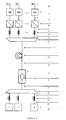
- the first proposed embodiment is shown in Fig. 2 .
- This embodiment comprises a ML source (1), optical connections (2), (6), (8), an electro-optic modulator (4), a 1 to N optical signal splitter (5), N TODL's based on the proposed MZDI (7), N photodetectors (9) and N elementary antennas (10).
- an electro-optic modulator (4) the monochromatic signal generated by the light source (1) is modulated by the electric RF signal (3) which will be radiated by the PAA.
- the modulated optical signal is split into N copies using a 1 to N optical splitter (6).
- Each one of the N copies is input into a TODL (7), which consists of a MZDI (7) with two arms and tunable coupling ratio.
- Each arm of the MZDI is a fixed optical delay line, where the propagation time difference of both arms is ⁇ .
- the time delay added to each copy of the modulated signal, before such copy enters its TODL (7), can be predefined by the length of the optical connections (6).
- each copy is converted to the electrical domain using a photodetector (9) and subsequently sent to the respective elementary antenna (10).
- the direction of the radiated electrical field is defined by manipulating the coupling ratios for the N TODL's (7).
- the second embodiment is shown in Fig. 3 .
- This embodiment also comprises a ML source (1), optical connections (2), (6), (8), an electro-optic modulator (4), a 1 to N optical signal splitter (5), N photodetectors (9) and N antennas (10).
- the new components are PC's (12), (16), a birefringent medium (14), N polarizers (18), and additional optical connections (11), (13), (15) and (17).
- This embodiment is essentially an optimized version of the embodiment depicted in Fig. 2 .
- the N interferometers of this embodiment share the input optical coupler.
- the modulated optical signal has a linear polarization state at the output of the electro-optic modulator (4).
- the birefringent medium (14) allows propagation of an optical signal along two orthogonal polarization axes, which have different propagation velocities. Therefore, this medium allows obtaining a time delay ⁇ between two orthogonally polarized optical signals aligned with the orthogonal polarization axes of the medium.
- the PC (12) sets the SOP of the modulated optical signal at an angle of 45° relative to one of the axes of the birefringent medium (14).
- At the output of said birefringent medium (14) two modulated optical signals, orthogonally polarized and time delayed by ⁇ between each other, are obtained. So, the PC (12) and the birefringent medium (14) are the input optical coupler and the delay lines of the proposed MZDI's.
- the optical splitter (5) is used to obtain N copies of the orthogonally polarized optical signals.
- the orthogonally polarized signals are added with different weights using the polarizers (18).
- the PC's (16) and the polarizers (18) are the output optical couplers with tunable coupling ratio of the proposed MZDI's.
- each signal copy is converted to the electrical domain using a photodetector (9) and subsequently sent to its respective elementary antenna (10).
- the direction of the radiated electrical field is defined through the manipulation of the PC's (16).
- the third embodiment is shown in Fig. 4 .
- This embodiment comprises N ML sources (19) optically connected to N PC's (21).
- the signals generated by the N ML sources are multiplexed in the wavelength, using a wavelength multiplexer (23) which is optically connected to the electro-optic modulator (4). All multiplexed signals are modulated the same way, and then introduced into the birefringent medium (14).
- the multiplexed signals at the output of the birefringent medium are now dye-multiplexed using a wavelength de-multiplexer (24) with N outputs, where each one of the N outputs is connected to a PC (16) and a polarizer (18).
- N photodetectors (9) and N elementary antennas (10) are the same as in previously described embodiments.
- previous embodiments are based on a ML source (1) and an optical splitter (5) which is not sensitive to the wavelength
- the present embodiment is based on wavelength multiplexing for N ML sources.
- the optical splitter (5) which is not sensitive to the wavelength is replaced by a wavelength multiplexer (23) and de-multiplexer (24).
- the MZDI associated with each ML source is now composed by a PC (21), the birefringent medium (14), another PC (16) and its respective polarizer (18).
- the coupling ratio and consequently the time delay associated to a ML source can be tuned through the PC (21).
- all the PC's (16) have the same function, which is to align the polarization axis of the birefringent medium (14) at an angle of 45° relative to one of the polarizer's axes (18).
- Such functions belonging to PC's (21) and (16) can be performed by PC's (16) and (21) respectively.
- the MZDI's can have both the input and output optical couplers with tunable coupling ratio.
- the fourth embodiment is shown in Fig. 5 .
- This embodiment is quite similar to the second embodiment sharing most of its functioning, but differs in the following details.
- the polarizers (18) were replaced by VOA's (25) sensitive to the polarization.
- This device allows an independent attenuation for the SOP's of the input optical signal.
- the PC's (16) are used to align the polarization orthogonal axes of the birefringent medium (14) with the polarization orthogonal axes of the device (25).
- the polarization orthogonal signals are not added to the electrical domain.
- the polarization orthogonal signals are simultaneously added in the photodetection process, which means the electrical signal consists in adding the polarization orthogonal signals detected.
- the MZDI's are therefore partly implemented both on the optical and electrical domains.
- the coupling ratio can be tuned through the adjustment of the VOA's (25) sensitive to polarization.
- To perform the addition in the electrical domain one needs that the phase information of the orthogonally polarized optical signals is preserved at the electrical domain.
- this embodiment is limited to optical signals with SSB modulation.
- the main difference between this and the second embodiment relates to the fact that this embodiment has a incoherent operation, unlike the third embodiment where orthogonally polarized optical signals are coherently added in optical domain polarization.
- the beamforming of the radiated electrical field is defined through the tuning of devices (25).
- the fifth embodiment is shown in Fig. 6 .
- This embodiment is quite similar to the third embodiment sharing most of its functioning, but differs in the following details.
- the polarizers (18) are replaced by VOA's (25) sensitive to polarization.
- the PC's (16) are used to align the orthogonal axes in the polarization of the birefringent medium (14) with the polarization orthogonal axes of the device (25).
- the purpose of these modifications is explained in fourth embodiment. Therefore, this embodiment is also limited to optical signals with SSB modulation.
- the main difference between this and the third embodiment relates to the fact that this embodiment has a incoherent operation, unlike the third embodiment where orthogonally polarized optical signals are coherently added in optical domain polarization.
- the beamforming of the radiated electrical field is defined through the tuning of devices (25).
Abstract
Description
- This invention discloses a photonic system and method with the purpose of beamforming the electric field yield by a phased array antenna (PAA). The system relies on a photonic tunable optical delay line (TODL), which is an Mach-Zehnder optical interferometer with a predefined differential time delay between arms. The time delay is tuned by adjusting the coupling ratio between the power applied to each one of the interferometer's delay lines. Three embodiments are proposed, wherein one of them just uses a single delay line and a single monochromatic light (ML) source, independently of the quantity of elementary antennas of the phased array. The application of the described TODL in a photonic system with the purpose of beamforming the electric field yield by a PAA has not been found in the present state of the art. The proposed system is apropriate to wireless communication systems with high frequency RF carriers, which allow handling with high data transmission rates.
- The proposed invention presents a novel approach in beamforming systems for the electric field radiated by a PAA. PAA's are being increasingly used, because such antennas allow directing the radiated beam precisely to any target direction, without using any mechanical displacement. Since the bandwidth of data transmission is growing in wired or wireless communication systems, interconnecting systems between both these types of communication systems are required, which allow high data transmission rates. Let us consider the following example: a wireless network system with high data transmission rates (≥ 1 Gb/s) can use a radio over fiber (RoF) system to connect a central office to a remote PAA. Subsequently, the PAA will direct the beam in a target direction using the proposed system, since it allows the acceptance of high data transmission rates. Another area of interest outside communication systems is radio astronomy, which requires advanced antenna technology to monitor signals arriving from outer space with low power and high bandwidths.
- In comparison with the photonic beamforming techniques reported so far, the proposed system is rather simple and is based on a well-known optics device, the Mach-Zehnder delay interferometer (MZDI). Its implementation is made with commercially available components. It also allows a very fast beam tuning, particularly when its implementation uses integrated optics. According to its inventors point of view, the main advantage is that it just requires one optical delay line (the birefringent medium in the embodiment shown in
Fig. 3 ) and a single ML source, independently of the quantity of elementary antennas. This feature was not found in any techniques reported in prior art's literature. - A PAA comprises N antennas disposed along the three spatial dimensions. The antennas which form the PAA are known as elementary antennas. A PAA allows the optimization and the beamforming of the radiated electrical field through the adjustment of the amplitude and phase of the radio frequency (RF) signals sent to each elementary antenna. This is an exclusive feature for the PAA's, since in an individual antenna the optimization of the radiated electrical field depends on the antenna's design. In addition, the beamforming of the radiated electrical field depends on the spatial orientation of the antenna.
- As previously said, the beamforming of the electrical field radiated by the PAA can be controlled through the phase of the RF signals applied to each elementary antenna. More precisely, the PAA can be fed by a single RF signal, which is split to all elementary antennas including a tunable phase shift. Although tunable, the phase shift is constant. This means the induced phase shift value is correct only for a specific RF frequency. In a PAA, this implies that the emitted frequency should be constant. Otherwise, different RF frequencies get different phase shifts, and so the beamforming of the electric field becomes dependent on the emitted frequency. In the case of data transmission over one RF carrier frequency, this implies that the data signal bandwidth should be as low as possible. Since there are many applications with high bandwidth (e.g., RADAR signals, Gb/s wireless networks, radio astronomy, etc.), the beamforming of the radiated electric field cannot be efficiently performed with such a technique.
- This problem can be solved using phase shifts that depend on RF frequency. In practice, a phase shift depending on frequency consists in a time delay line. Therefore, instead of a phase shift, each elementary antenna should include a tunable time delay. The electrical implementation of a tunable time delay is particularly challenging at high frequencies, since increasing time delays implies increasing the length of the delay line, which in turn leads to greater insertion losses and a reduction in bandwidth. Such disadvantages are overcome using photonic implementations of tunable delay lines. The advantages of photonic systems consist on low losses, broad bandwidth, lighter weights, smaller dimensions and immunity to electromagnetic interference. Generally, a PAA with tunable photonic delay lines is characterized in that it has an electro-optical modulator, which converts the RF signal to the optical domain, followed by an optical processing system which delays and distributes the modulated optical signal according to what the needs of the different antennas are. The optical signals are converted to the electrical domain using photodetectors.
- The patents summarized below describe different implementations of photonic TODL's, which can be applied to PAA.
-
US patent 5428218 discloses a photonic TODL based on spatial multiplexing. In such free-space implementation, the optical signal is directed into a given optical fiber through the adjustment of mirrors. As different optical fibers have different lengths, one can get a discrete tuning of the time delay added to the optical signal. This implementation also includes the possibility of having a multi-beam system, e.g., the system can be simultaneously used by more than one optical signal. -
US patent 5978125 discloses a photonic TODL based on polarization multiplexing. In a birefringent medium, an optical signal with a specific state-of-polarization (SOP) has a higher time delay than the orthogonal SOP. By selecting one of the two SOP's, the added time delay can then be controlled. This method is described in a cascaded configuration, in which serial birefringent media are intercalated by polarization controllers (PC's). As a result, a discrete delay tuning is obtained. -
US patent 5461687 discloses a photonic TODL based on dispersive means. By tuning the wavelength of the input optical signal the path by which the signal propagates changes, resulting in a tunable time delay. In this patent, the dispersive mean is implemented in a free space using a diffraction grating. Another possible option is to use fiber Bragg gratings (FBG's) located in different points of an optical fiber. -
US patent 5751466 discloses a photonic TODL which uses the frequency response of a photonic bandgap device. An example of such a device is a FBG. This device consists of a dielectric structure in which the refractive index varies longitudinally. The control of the refractive index's variation along the structure results in changing the frequency response of the device, therefore affecting the time delay added to the photonic signal. -
US patent 7558450 B2 discloses a photonic TODL composed by three resonant elements coupled to a waveguide. This implementation is limited to single sideband (SSB) optical signals. The symmetric displacement in the frequency of two resonant elements enables the adjustment of time delay induced to the RF carrier. The third resonant element adjusts the phase of the optical carrier (OC) in order to avoid involuntary phase shifting of RF signal. Of greater importance than the tuning method, is the fact that this patent is clearly appropriate to RF signals without any spectral content between the optical and the RF carriers. As a result, the TODL's frequency response is irrelevant at frequencies located between the RF carrier and the OC. - The following description is based on the drawings attached hereto, which are represented without any restrictions:
- In
Fig. 1 the response in amplitude and the photonic TODL group delay, considering different coupling ratios α among the power applied to each one of the interferometer's optical delay lines. -
Fig 2 shows a first embodiment of the invention; -
Fig 3 shows a second embodiment of the invention; and -
Fig 4 shows a third embodiment of the invention. -
Fig 5 shows a fourth embodiment of the invention. -
Fig 6 shows a fifth embodiment of the invention. - The system proposed for beamforming the electric field yield by a PAA can be divided in three subsystems. In the first subsystem, the RF signal modulates a monochromatic optical carrier. The resulting modulated optical signal is split into N copies, where N is the number of elementary antennas. Each copy is introduced into a TODL, and then reconverted to the electrical domain by means of a photodetector. Each photodetector is connected to the respective elementary antenna.
- The key element of a beamforming system is the tunable delay line, because generally a PAA with N antennas requires N tunable delay lines. The proposed TODL consists of a MZDI with two arms. The MZDI is composed of an input optical coupler to which two delay lines and an output coupler which adds the signals coming from both lines. The delay lines have a fixed time delay difference τ. One of the optical couplers has a tunable coupling ratio, i.e., the optical power ratio in the two delay lines can be tuned. According to what is claimed in patent
PT 104237 
where 0≤α≤1 is the coupling ratio and f is the frequency. The amplitude response ∥H(f)∥2 and the group delay τ(f) can be derived from (1),

- Both derived equations show that the TODL has a periodic frequency response with a
period 1/τ. The amplitude response and the group delay are depicted inFigure 1 for different values of α. As predicted by (2.1) and (2.2), both the amplitude response and the group delay are affected by α. As a result, the optical signal must be properly centered with the MZDI's frequency response. The absolute value of the amplitude response can be adjusted by means of variable optical attenuators (VOA's), located at the input or output of the TODL's, or using electrical amplifiers for the signals detected. - Generally, a RF signal modulated over an OC has three spectral lines located at f 0-f RF, f 0 and f 0+f RF, where f 0 is the OC frequency and f RF is the frequency of the RF signal. In the case of data transmission, copies of the transmitted sequence spectrum are centered at the three spectral lines. Thus, there are two ways for centering the modulated signal spectrum with the MZDI's frequency response. The first one consists of setting all the three spectral lines within a single period of the MZDI's response. The other way makes use of the fact that the TODL's frequency response is irrelevant to frequencies located between the RF carriers and the OC. Each one of the spectral lines is then centered at different maxima of the MZDI's amplitude response.
- The implementation of the proposed photonic system for beamforming the electric field radiated by a PAA is presented through five different architectures.
- The first proposed embodiment is shown in
Fig. 2 . This embodiment comprises a ML source (1), optical connections (2), (6), (8), an electro-optic modulator (4), a 1 to N optical signal splitter (5), N TODL's based on the proposed MZDI (7), N photodetectors (9) and N elementary antennas (10). By means of an electro-optic modulator (4), the monochromatic signal generated by the light source (1) is modulated by the electric RF signal (3) which will be radiated by the PAA. The modulated optical signal is split into N copies using a 1 to N optical splitter (6). Each one of the N copies is input into a TODL (7), which consists of a MZDI (7) with two arms and tunable coupling ratio. Each arm of the MZDI is a fixed optical delay line, where the propagation time difference of both arms is τ. The time delay added to each copy of the modulated signal, before such copy enters its TODL (7), can be predefined by the length of the optical connections (6). After being time delayed, each copy is converted to the electrical domain using a photodetector (9) and subsequently sent to the respective elementary antenna (10). Briefly, the direction of the radiated electrical field is defined by manipulating the coupling ratios for the N TODL's (7). - The second embodiment is shown in
Fig. 3 . This embodiment also comprises a ML source (1), optical connections (2), (6), (8), an electro-optic modulator (4), a 1 to N optical signal splitter (5), N photodetectors (9) and N antennas (10). The new components are PC's (12), (16), a birefringent medium (14), N polarizers (18), and additional optical connections (11), (13), (15) and (17). This embodiment is essentially an optimized version of the embodiment depicted inFig. 2 . Instead of the N independent MZDI's (7), the N interferometers of this embodiment share the input optical coupler. The modulated optical signal has a linear polarization state at the output of the electro-optic modulator (4). The birefringent medium (14) allows propagation of an optical signal along two orthogonal polarization axes, which have different propagation velocities. Therefore, this medium allows obtaining a time delay τ between two orthogonally polarized optical signals aligned with the orthogonal polarization axes of the medium. The PC (12) sets the SOP of the modulated optical signal at an angle of 45° relative to one of the axes of the birefringent medium (14). At the output of said birefringent medium (14) two modulated optical signals, orthogonally polarized and time delayed by τ between each other, are obtained. So, the PC (12) and the birefringent medium (14) are the input optical coupler and the delay lines of the proposed MZDI's. The optical splitter (5) is used to obtain N copies of the orthogonally polarized optical signals. Depending on the angular orientation set by the PC's (16), the orthogonally polarized signals are added with different weights using the polarizers (18). Hence, the PC's (16) and the polarizers (18) are the output optical couplers with tunable coupling ratio of the proposed MZDI's. After being time delayed, each signal copy is converted to the electrical domain using a photodetector (9) and subsequently sent to its respective elementary antenna (10). Briefly, the direction of the radiated electrical field is defined through the manipulation of the PC's (16). - The third embodiment is shown in
Fig. 4 . This embodiment comprises N ML sources (19) optically connected to N PC's (21). The signals generated by the N ML sources are multiplexed in the wavelength, using a wavelength multiplexer (23) which is optically connected to the electro-optic modulator (4). All multiplexed signals are modulated the same way, and then introduced into the birefringent medium (14). The multiplexed signals at the output of the birefringent medium are now dye-multiplexed using a wavelength de-multiplexer (24) with N outputs, where each one of the N outputs is connected to a PC (16) and a polarizer (18). Several optical connections are presented at (20), (22), (2), (11), (15), (6), (17) and (8). Of course, the N photodetectors (9) and N elementary antennas (10) are the same as in previously described embodiments. Although previous embodiments are based on a ML source (1) and an optical splitter (5) which is not sensitive to the wavelength, the present embodiment is based on wavelength multiplexing for N ML sources. The optical splitter (5) which is not sensitive to the wavelength is replaced by a wavelength multiplexer (23) and de-multiplexer (24). The MZDI associated with each ML source is now composed by a PC (21), the birefringent medium (14), another PC (16) and its respective polarizer (18). The coupling ratio and consequently the time delay associated to a ML source can be tuned through the PC (21). Here, all the PC's (16) have the same function, which is to align the polarization axis of the birefringent medium (14) at an angle of 45° relative to one of the polarizer's axes (18). Such functions belonging to PC's (21) and (16) can be performed by PC's (16) and (21) respectively. It should be noted that, in the first situation, it is required that the electro-optic modulator is not sensitive to the polarization of the ML sources (19). Therefore, in this embodiment the MZDI's can have both the input and output optical couplers with tunable coupling ratio. - The fourth embodiment is shown in
Fig. 5 . This embodiment is quite similar to the second embodiment sharing most of its functioning, but differs in the following details. The polarizers (18) were replaced by VOA's (25) sensitive to the polarization. This device allows an independent attenuation for the SOP's of the input optical signal. The PC's (16) are used to align the polarization orthogonal axes of the birefringent medium (14) with the polarization orthogonal axes of the device (25). As a consequence of the replacement of polarizers (18) by devices (25), the polarization orthogonal signals are not added to the electrical domain. In this embodiment, the polarization orthogonal signals are simultaneously added in the photodetection process, which means the electrical signal consists in adding the polarization orthogonal signals detected. The MZDI's are therefore partly implemented both on the optical and electrical domains. The coupling ratio can be tuned through the adjustment of the VOA's (25) sensitive to polarization. To perform the addition in the electrical domain, one needs that the phase information of the orthogonally polarized optical signals is preserved at the electrical domain. As a result, this embodiment is limited to optical signals with SSB modulation. The main difference between this and the second embodiment relates to the fact that this embodiment has a incoherent operation, unlike the third embodiment where orthogonally polarized optical signals are coherently added in optical domain polarization. Briefly, the beamforming of the radiated electrical field is defined through the tuning of devices (25). - The fifth embodiment is shown in
Fig. 6 . This embodiment is quite similar to the third embodiment sharing most of its functioning, but differs in the following details. The polarizers (18) are replaced by VOA's (25) sensitive to polarization. The PC's (16) are used to align the orthogonal axes in the polarization of the birefringent medium (14) with the polarization orthogonal axes of the device (25). The purpose of these modifications is explained in fourth embodiment. Therefore, this embodiment is also limited to optical signals with SSB modulation. The main difference between this and the third embodiment relates to the fact that this embodiment has a incoherent operation, unlike the third embodiment where orthogonally polarized optical signals are coherently added in optical domain polarization. Briefly, the beamforming of the radiated electrical field is defined through the tuning of devices (25).
Claims (11)
- A photonic system to perform the tunable beamforming of the electric field radiated by a phased array antenna characterized in that it comprises: at least one monochromatic light source, an electro-optic modulator, and a 1 to N optical signal splitter, in which each of the N outputs of the 1 to N optical signal splitter is optically connected to at least one Mach-Zehnder optic interferometer, a photodetector and one of the N elementary antennas that compose the phased array antenna.
- A photonic system to perform the tunable beamforming of the electric field radiated by a phased array antenna according to claim 1, characterized in that each Mach-Zehnder optic interferometer comprises an input optical coupler optically connected to at least two time delay lines with a time difference between them, which are optically connected to an output optical coupler; and in that at least one of the two optical couplers that compose each Mach-Zehnder optic interferometer has a tunable coupling ratio.
- The photonic system to perform the tunable beamforming of the electric field radiated by a phased array antenna according to the previous claims, characterized in that each one of the at least N optic interferometers represents a tunable delay line; and in that the time tuning is performed through the control of the coupling ratio of at least one of the two optical couplers.
- The phetonic system to perform the tunable beamforming of the electric field radiated by a phased array antenna according to the previous claims, characterized in that the coupling ratio of at least N optic Mach-Zehnder interferometers is controlled to permit the tuning of the radiated electric field beamforming.
- The photonic system to perform the tunable beamforming of the electric field radiated by a phased array antenna according to the previous claims, characterized in that another kind of optic interferometer can be used, besides Mach-Zehnder, as long as it permits to perform the time delay tuning through the adjustment of the power coupling ratio between the arms.
- The photonic system to perform the tunable beamforming of electric field radiated by a phased array antenna according to the previous claims, characterized in that it can comprise N variable optical attenuators placed after the outputs of the 1 to N optical splitter in order to enable controlling the power of the detected N optical signals.
- Method to perform the beamforming of the electric field radiated by a phased array antenna according to claim 1, characterized in that at least one monochromatic light source is modulated by the RF signal which is going to be radiated using an electro-optic modulator; in that the modulated signals are copied N times, where each copy is processed by at least one Mach-Zehnder optic interferometer with tunable coupling ratio, being next converted to the electric domain through photodetection, and being then sent to the respective elementary antenna of the phased array antenna; throughout controlling the interferometers coupling ratio, the time delay associated to each one of the N copies is varied, and therefore the beamforming of the electric field radiated by the phased array antenna can be controlled.
- Method to perform the beamforming of the electric field radiated by a phased array antenna according to claim 7, characterized in that it comprises a monochromatic light source, an electro-optic modulator and N Mach-Zehnder optic interferometers with tunable coupling ratio, composed as follows: the modulated signal is split with equal power by the two propagation axes of a birefringent medium, obtaining at the output of the birefringent medium two polarization orthogonal optic signals, time delayed between each other by τ; the polarization orthogonal optic signals are copied N times by an 1 to N optic signal splitter; the polarization orthogonal optic signals of each of the N copies are added using a polarizer; the coupling ratio of each Mach-Zehnder optic interferometer, and consequently the time delay of each copy, can be tuned through the polarization controller, which is previous tc the respective polarizer.
- Method to perform the beamforming of the electric field radiated by a phased array antenna according to claim 7, characterized in that it has N monochromatic light sources, multiplexed at the wavelength using a wavelength multiplexer optically connected to an electro-optic modulator which is optically connected to N optic Mach-Zehnder interferometers with tunable coupling ratio, composed as follows: the N modulated signals are introduced into a birefringent medium; the polarization of the N modulated signals introduced into the birefringent medium can be adjusted using the polarization controllers which come after the N monochromatic sources; at the output of the birefringent medium, each wavelength multiplexed signal is de-multiplexed using a wavelength de-multiplexer, and the orthogonally polarized signals which compose each de-multiplexed signal are added using a polarizer; the coupling ratio can be defined by adjusting the polarization controllers which come after each monochromatic source and/or the polarization controllers which come before the polarizers.
- Method to perform the beamforming of the electric field radiated by a phased array antenna according to claim 7, characterized in that it has a monochromatic light source, an electro-optic modulator that converts the electric signal in an optic signal with single side band, and N Mach-zehnder optoelectric interferometers with tunable coupling ratio, composed as follows: the modulated signal is divided with equal power between the two propagation axes of a birefringent medium, obtaining at the output of the birefringent medium two polarization orthogonal optic signals, time delayed between each other by τ; the polarization orthogonal optic signals are copied N times by an 1 to N optic signal splitter; the polarization orthogonal signals of each of the N copies are attenuated independently by an optically variable attenuator, sensitive to polarization; the coupling ratio, and consequently the time delay of each copy can be tuned using optically variable attenuator, which is sensitive to polarization, that comes before the respective photodetector, which, in turn adds the polarization orthogonal signals detected simultaneously to the photodetection.
- Method to perform the to perform the beamforming of the electric field radiated by a phased array antenna according to claim 7, characterized in that it has N monochromatic light sources, multiplexed at wavelength using a wavelength multiplexer, optically connected to an electro-optic modulator, which converts the electric signal into an optical signal with single sideband, and in turn is optically connected to N Mach-Zehnder optic interferometers with tunable coupling ratio, composed as follows: the modulated signals are divided with equal power between the two propagation axis of a birefringent medium, through the adjustment of the polarization controllers that come after the N monochromatic sources and through the adjustment of one polarization controller that comes before the birefringent medium; at the output of the birefringent medium, each wavelength multiplexed signal is de-multiplexed using a wavelength de-multiplexer and the orthogonally polarized signals that compose each de-multiplexed signal are attenuated independently by an optically variable attenuator that is sensitive to polarization; the coupling ratio, and consequently the time delay of each copy can be tuned using optically variable attenuator, which is sensitive to polarization, that comes before the respective photodetector, which, in turn adds the polarization orthogonal signals detected simultaneously to the photodetection.
Applications Claiming Priority (2)
| Application Number | Priority Date | Filing Date | Title |
|---|---|---|---|
| PT105190A PT105190A (en) | 2010-07-08 | 2010-07-08 | SYSTEM AND PHOTONIC METHOD FOR PERFORMING THE TUNING DIRECTIONATION OF THE ELECTRIC FIELD RADIATED BY AN AGGREGATE OF ANTENNAS |
| PCT/PT2010/000061 WO2012005618A1 (en) | 2010-07-08 | 2010-12-09 | Photonic system and method for tunable beamforming of the electric field radiated by a phased array antenna |
Publications (2)
| Publication Number | Publication Date |
|---|---|
| EP2592768A1 true EP2592768A1 (en) | 2013-05-15 |
| EP2592768B1 EP2592768B1 (en) | 2018-05-02 |
Family
ID=43836706
Family Applications (1)
| Application Number | Title | Priority Date | Filing Date |
|---|---|---|---|
| EP10809198.4A Not-in-force EP2592768B1 (en) | 2010-07-08 | 2010-12-09 | Photonic system and method for tunable beamforming of the electric field radiated by a phased array antenna |
Country Status (5)
| Country | Link |
|---|---|
| US (1) | US9257745B2 (en) |
| EP (1) | EP2592768B1 (en) |
| CN (1) | CN103222207B (en) |
| PT (1) | PT105190A (en) |
| WO (1) | WO2012005618A1 (en) |
Cited By (3)
| Publication number | Priority date | Publication date | Assignee | Title |
|---|---|---|---|---|
| WO2016170466A1 (en) * | 2015-04-20 | 2016-10-27 | Instituto De Telecomunicações | Photonic beamforming system for a phased array antenna receiver |
| KR20180039948A (en) * | 2016-10-11 | 2018-04-19 | 한국과학기술원 | Photonic beam forming network chip based on silicon semiconductor |
| CN111095673A (en) * | 2017-08-08 | 2020-05-01 | 泰雷兹公司 | Device for optically receiving signals from a phased antenna array and antenna system |
Families Citing this family (11)
| Publication number | Priority date | Publication date | Assignee | Title |
|---|---|---|---|---|
| US10003131B2 (en) * | 2013-11-19 | 2018-06-19 | At&T Intellectual Property I, L.P. | System and method of optical antenna tuning |
| JP6249838B2 (en) * | 2014-03-18 | 2017-12-20 | Kddi株式会社 | ANTENNA LIGHT CONTROL DEVICE, ANTENNA LIGHT CONTROL SYSTEM, ANTENNA LIGHT CONTROL METHOD, AND PROGRAM |
| US9590706B1 (en) * | 2015-09-16 | 2017-03-07 | Motorola Mobility Llc | Method and apparatus for equal energy codebooks for antenna arrays with mutual coupling |
| CN105609954B (en) * | 2015-10-30 | 2018-07-24 | 中国电子科技集团公司第二十九研究所 | An a kind of width based on optical instrument/mutually weight implementation method and device |
| US10439282B2 (en) * | 2016-01-19 | 2019-10-08 | Phase Sensitive Innovations, Inc. | Beam steering antenna transmitter, multi-user antenna MIMO transmitter and related methods of communication |
| IT201700053579A1 (en) | 2017-05-17 | 2018-11-17 | Milano Politecnico | METHOD AND OPTICAL DELAY SYSTEM |
| US11005178B2 (en) | 2017-11-21 | 2021-05-11 | Phase Sensitive Innovations, Inc. | Antenna and antenna array configurations, antenna systems and related methods of operation |
| US11567189B2 (en) | 2018-02-15 | 2023-01-31 | The Trustees Of The University Of Pennsylvania | Optically assisted ultra-wideband (UWB) imager |
| KR102470140B1 (en) * | 2018-09-03 | 2022-11-24 | 한국전자통신연구원 | Apparatus and method for beamformaing communications |
| CN113376928B (en) * | 2021-06-15 | 2023-04-14 | 上海电子信息职业技术学院 | Integrated photoelectron mixed bit reversible logic gate |
| CN117031480B (en) * | 2023-10-08 | 2024-03-15 | 之江实验室 | Coherent microwave photon radar detection method and system |
Family Cites Families (11)
| Publication number | Priority date | Publication date | Assignee | Title |
|---|---|---|---|---|
| US5461687A (en) * | 1992-03-18 | 1995-10-24 | Trw Inc. | Wavelength controlled optical true time delay generator |
| US5333000A (en) * | 1992-04-03 | 1994-07-26 | The United States Of America As Represented By The United States Department Of Energy | Coherent optical monolithic phased-array antenna steering system |
| US5274385A (en) | 1992-06-18 | 1993-12-28 | General Electric Company | Optical time delay units for phased array antennas |
| US5428218A (en) * | 1993-09-30 | 1995-06-27 | The United States Of America As Represented By The Secretary Of The Air Force | Variable time-delay system for broadband phased array and other transversal filtering applications |
| US5994891A (en) * | 1994-09-26 | 1999-11-30 | The Boeing Company | Electrically small, wideband, high dynamic range antenna having a serial array of optical modulators |
| US5978125A (en) * | 1995-11-30 | 1999-11-02 | Yao; X. Steve | Compact programmable photonic variable delay devices |
| US5751466A (en) | 1996-01-11 | 1998-05-12 | University Of Alabama At Huntsville | Photonic bandgap apparatus and method for delaying photonic signals |
| US6124827A (en) * | 1996-12-30 | 2000-09-26 | Green; Leon | Photonic phase and time delay-steered arrays |
| JP3444270B2 (en) * | 2000-05-23 | 2003-09-08 | 日本電気株式会社 | Array antenna receiver calibration system |
| US7558450B2 (en) * | 2007-09-06 | 2009-07-07 | Morton Photonics, Inc. | Microwave photonic delay line with separate tuning of optical carrier |
| PT104237B (en) | 2008-10-28 | 2010-12-28 | Univ Aveiro | OPTICAL FILTER WITH CONTINUOUS TUNING RESPONSE BASED ON COMBINATION OF DIFFERENT OPTICAL FILTERS |
-
2010
- 2010-07-08 PT PT105190A patent/PT105190A/en not_active IP Right Cessation
- 2010-12-09 WO PCT/PT2010/000061 patent/WO2012005618A1/en active Application Filing
- 2010-12-09 EP EP10809198.4A patent/EP2592768B1/en not_active Not-in-force
- 2010-12-09 US US13/808,996 patent/US9257745B2/en not_active Expired - Fee Related
- 2010-12-09 CN CN201080068628.5A patent/CN103222207B/en not_active Expired - Fee Related
Non-Patent Citations (1)
| Title |
|---|
| See references of WO2012005618A1 * |
Cited By (5)
| Publication number | Priority date | Publication date | Assignee | Title |
|---|---|---|---|---|
| WO2016170466A1 (en) * | 2015-04-20 | 2016-10-27 | Instituto De Telecomunicações | Photonic beamforming system for a phased array antenna receiver |
| US10224628B2 (en) | 2015-04-20 | 2019-03-05 | Instituto De Telecommunicações | Photonic beamforming system for a phased array antenna receiver |
| KR20180039948A (en) * | 2016-10-11 | 2018-04-19 | 한국과학기술원 | Photonic beam forming network chip based on silicon semiconductor |
| KR101892357B1 (en) | 2016-10-11 | 2018-08-27 | 한국과학기술원 | Photonic beam forming network chip based on silicon semiconductor |
| CN111095673A (en) * | 2017-08-08 | 2020-05-01 | 泰雷兹公司 | Device for optically receiving signals from a phased antenna array and antenna system |
Also Published As
| Publication number | Publication date |
|---|---|
| CN103222207B (en) | 2016-04-27 |
| US20130169483A1 (en) | 2013-07-04 |
| WO2012005618A1 (en) | 2012-01-12 |
| CN103222207A (en) | 2013-07-24 |
| PT105190A (en) | 2012-01-09 |
| EP2592768B1 (en) | 2018-05-02 |
| US9257745B2 (en) | 2016-02-09 |
Similar Documents
| Publication | Publication Date | Title |
|---|---|---|
| EP2592768B1 (en) | Photonic system and method for tunable beamforming of the electric field radiated by a phased array antenna | |
| US11243352B2 (en) | Polarization independent processing in integrated photonics | |
| US6594408B1 (en) | Method for compensating polarization mode dispersion in a waveguide and a polarization mode dispersion compensator | |
| US6628850B1 (en) | Dynamic wavelength-selective grating modulator | |
| US6137442A (en) | Chirped fiber grating beamformer for phased array antennas | |
| EP0254509B1 (en) | Wavelength sensitive optical devices | |
| US6388785B2 (en) | Optical compensation for dispersion-induced power fading in optical transmission of double-sideband signals | |
| US6400869B2 (en) | Tunable compensation for polarization-mode dispersion using a birefringent nonlinearly-chirped bragg grating in a dual-pass configuration | |
| EP3164953B1 (en) | Feed signal generation for a phased array antenna | |
| US20020005970A1 (en) | Dispersion compensator and method of compensating for dispersion | |
| Lee et al. | Optical Dispersion Compensator With $≫ $4000-ps/nm Tuning Range Using a Virtually Imaged Phased Array (VIPA) and Spatial Light Modulator (SLM) | |
| US6907199B2 (en) | Method for polarization mode dispersion compensation | |
| US6748126B2 (en) | System for polarization mode dispersion compensation | |
| KR20130093839A (en) | Optical transmitters and optical communication systems using thermal coupled resonance modulator | |
| JPH0369927A (en) | Polarization batch control method | |
| US11206085B2 (en) | Chromatic dispersion compensation | |
| EP1410100B1 (en) | Fiber optical gain equalizer | |
| JP3932769B2 (en) | Wavelength dispersion device, wavelength dispersion method, and optical transmission system | |
| US20170294925A1 (en) | Multi-Bit Digital To Analog-Optical Conversion Based On The Kerr Effect | |
| KR100860549B1 (en) | Optical signal processing system based on polarization modulation and optical signal processing method | |
| Tkachenko et al. | BEAM-FORMING DEVICES OF THE PHASED ARRAYANTENNA OF THE 5G NETWORK BASE STATION USING MICROWAVE PHOTONIC TECHNOLOGIES | |
| CN116846507A (en) | Silicon-based multi-beam forming network chip shared by delay units | |
| JP2018205646A (en) | Two-lightwave phase adjustment device | |
| Blais et al. | Single sideband modulation scheme employing an equivalent phase shifted fiber Bragg grating for a remotely controlled photonic true time-delay beamforming system | |
| Vidal et al. | Photonic tunable microwave transversal filter based on optical switches and fiber dispersion |
Legal Events
| Date | Code | Title | Description |
|---|---|---|---|
| PUAI | Public reference made under article 153(3) epc to a published international application that has entered the european phase |
Free format text: ORIGINAL CODE: 0009012 |
|
| 17P | Request for examination filed |
Effective date: 20130123 |
|
| AK | Designated contracting states |
Kind code of ref document: A1 Designated state(s): AL AT BE BG CH CY CZ DE DK EE ES FI FR GB GR HR HU IE IS IT LI LT LU LV MC MK MT NL NO PL PT RO RS SE SI SK SM TR |
|
| DAX | Request for extension of the european patent (deleted) | ||
| 17Q | First examination report despatched |
Effective date: 20170220 |
|
| REG | Reference to a national code |
Ref country code: DE Ref legal event code: R079 Ref document number: 602010050413 Country of ref document: DE Free format text: PREVIOUS MAIN CLASS: H04B0010120000 Ipc: H04B0010257500 |
|
| RAP1 | Party data changed (applicant data changed or rights of an application transferred) |
Owner name: INSTITUTO DE TELECOMUNICACOES |
|
| GRAP | Despatch of communication of intention to grant a patent |
Free format text: ORIGINAL CODE: EPIDOSNIGR1 |
|
| RIC1 | Information provided on ipc code assigned before grant |
Ipc: H04B 10/2575 20130101AFI20171020BHEP Ipc: H01Q 3/26 20060101ALI20171020BHEP |
|
| INTG | Intention to grant announced |
Effective date: 20171130 |
|
| GRAS | Grant fee paid |
Free format text: ORIGINAL CODE: EPIDOSNIGR3 |
|
| GRAA | (expected) grant |
Free format text: ORIGINAL CODE: 0009210 |
|
| AK | Designated contracting states |
Kind code of ref document: B1 Designated state(s): AL AT BE BG CH CY CZ DE DK EE ES FI FR GB GR HR HU IE IS IT LI LT LU LV MC MK MT NL NO PL PT RO RS SE SI SK SM TR |
|
| REG | Reference to a national code |
Ref country code: GB Ref legal event code: FG4D |
|
| REG | Reference to a national code |
Ref country code: CH Ref legal event code: EP Ref country code: AT Ref legal event code: REF Ref document number: 996338 Country of ref document: AT Kind code of ref document: T Effective date: 20180515 |
|
| REG | Reference to a national code |
Ref country code: DE Ref legal event code: R096 Ref document number: 602010050413 Country of ref document: DE Ref country code: IE Ref legal event code: FG4D |
|
| REG | Reference to a national code |
Ref country code: NL Ref legal event code: MP Effective date: 20180502 |
|
| REG | Reference to a national code |
Ref country code: LT Ref legal event code: MG4D |
|
| PG25 | Lapsed in a contracting state [announced via postgrant information from national office to epo] |
Ref country code: SE Free format text: LAPSE BECAUSE OF FAILURE TO SUBMIT A TRANSLATION OF THE DESCRIPTION OR TO PAY THE FEE WITHIN THE PRESCRIBED TIME-LIMIT Effective date: 20180502 Ref country code: LT Free format text: LAPSE BECAUSE OF FAILURE TO SUBMIT A TRANSLATION OF THE DESCRIPTION OR TO PAY THE FEE WITHIN THE PRESCRIBED TIME-LIMIT Effective date: 20180502 Ref country code: ES Free format text: LAPSE BECAUSE OF FAILURE TO SUBMIT A TRANSLATION OF THE DESCRIPTION OR TO PAY THE FEE WITHIN THE PRESCRIBED TIME-LIMIT Effective date: 20180502 Ref country code: BG Free format text: LAPSE BECAUSE OF FAILURE TO SUBMIT A TRANSLATION OF THE DESCRIPTION OR TO PAY THE FEE WITHIN THE PRESCRIBED TIME-LIMIT Effective date: 20180802 Ref country code: FI Free format text: LAPSE BECAUSE OF FAILURE TO SUBMIT A TRANSLATION OF THE DESCRIPTION OR TO PAY THE FEE WITHIN THE PRESCRIBED TIME-LIMIT Effective date: 20180502 Ref country code: NO Free format text: LAPSE BECAUSE OF FAILURE TO SUBMIT A TRANSLATION OF THE DESCRIPTION OR TO PAY THE FEE WITHIN THE PRESCRIBED TIME-LIMIT Effective date: 20180802 |
|
| PG25 | Lapsed in a contracting state [announced via postgrant information from national office to epo] |
Ref country code: LV Free format text: LAPSE BECAUSE OF FAILURE TO SUBMIT A TRANSLATION OF THE DESCRIPTION OR TO PAY THE FEE WITHIN THE PRESCRIBED TIME-LIMIT Effective date: 20180502 Ref country code: HR Free format text: LAPSE BECAUSE OF FAILURE TO SUBMIT A TRANSLATION OF THE DESCRIPTION OR TO PAY THE FEE WITHIN THE PRESCRIBED TIME-LIMIT Effective date: 20180502 Ref country code: RS Free format text: LAPSE BECAUSE OF FAILURE TO SUBMIT A TRANSLATION OF THE DESCRIPTION OR TO PAY THE FEE WITHIN THE PRESCRIBED TIME-LIMIT Effective date: 20180502 Ref country code: NL Free format text: LAPSE BECAUSE OF FAILURE TO SUBMIT A TRANSLATION OF THE DESCRIPTION OR TO PAY THE FEE WITHIN THE PRESCRIBED TIME-LIMIT Effective date: 20180502 |
|
| REG | Reference to a national code |
Ref country code: AT Ref legal event code: MK05 Ref document number: 996338 Country of ref document: AT Kind code of ref document: T Effective date: 20180502 |
|
| PG25 | Lapsed in a contracting state [announced via postgrant information from national office to epo] |
Ref country code: CZ Free format text: LAPSE BECAUSE OF FAILURE TO SUBMIT A TRANSLATION OF THE DESCRIPTION OR TO PAY THE FEE WITHIN THE PRESCRIBED TIME-LIMIT Effective date: 20180502 Ref country code: RO Free format text: LAPSE BECAUSE OF FAILURE TO SUBMIT A TRANSLATION OF THE DESCRIPTION OR TO PAY THE FEE WITHIN THE PRESCRIBED TIME-LIMIT Effective date: 20180502 Ref country code: PL Free format text: LAPSE BECAUSE OF FAILURE TO SUBMIT A TRANSLATION OF THE DESCRIPTION OR TO PAY THE FEE WITHIN THE PRESCRIBED TIME-LIMIT Effective date: 20180502 Ref country code: EE Free format text: LAPSE BECAUSE OF FAILURE TO SUBMIT A TRANSLATION OF THE DESCRIPTION OR TO PAY THE FEE WITHIN THE PRESCRIBED TIME-LIMIT Effective date: 20180502 Ref country code: SK Free format text: LAPSE BECAUSE OF FAILURE TO SUBMIT A TRANSLATION OF THE DESCRIPTION OR TO PAY THE FEE WITHIN THE PRESCRIBED TIME-LIMIT Effective date: 20180502 Ref country code: DK Free format text: LAPSE BECAUSE OF FAILURE TO SUBMIT A TRANSLATION OF THE DESCRIPTION OR TO PAY THE FEE WITHIN THE PRESCRIBED TIME-LIMIT Effective date: 20180502 Ref country code: AT Free format text: LAPSE BECAUSE OF FAILURE TO SUBMIT A TRANSLATION OF THE DESCRIPTION OR TO PAY THE FEE WITHIN THE PRESCRIBED TIME-LIMIT Effective date: 20180502 |
|
| REG | Reference to a national code |
Ref country code: DE Ref legal event code: R097 Ref document number: 602010050413 Country of ref document: DE |
|
| PG25 | Lapsed in a contracting state [announced via postgrant information from national office to epo] |
Ref country code: SM Free format text: LAPSE BECAUSE OF FAILURE TO SUBMIT A TRANSLATION OF THE DESCRIPTION OR TO PAY THE FEE WITHIN THE PRESCRIBED TIME-LIMIT Effective date: 20180502 |
|
| PLBE | No opposition filed within time limit |
Free format text: ORIGINAL CODE: 0009261 |
|
| STAA | Information on the status of an ep patent application or granted ep patent |
Free format text: STATUS: NO OPPOSITION FILED WITHIN TIME LIMIT |
|
| 26N | No opposition filed |
Effective date: 20190205 |
|
| PG25 | Lapsed in a contracting state [announced via postgrant information from national office to epo] |
Ref country code: SI Free format text: LAPSE BECAUSE OF FAILURE TO SUBMIT A TRANSLATION OF THE DESCRIPTION OR TO PAY THE FEE WITHIN THE PRESCRIBED TIME-LIMIT Effective date: 20180502 |
|
| REG | Reference to a national code |
Ref country code: CH Ref legal event code: PL |
|
| PG25 | Lapsed in a contracting state [announced via postgrant information from national office to epo] |
Ref country code: MC Free format text: LAPSE BECAUSE OF FAILURE TO SUBMIT A TRANSLATION OF THE DESCRIPTION OR TO PAY THE FEE WITHIN THE PRESCRIBED TIME-LIMIT Effective date: 20180502 Ref country code: LU Free format text: LAPSE BECAUSE OF NON-PAYMENT OF DUE FEES Effective date: 20181209 |
|
| REG | Reference to a national code |
Ref country code: IE Ref legal event code: MM4A |
|
| REG | Reference to a national code |
Ref country code: BE Ref legal event code: MM Effective date: 20181231 |
|
| PG25 | Lapsed in a contracting state [announced via postgrant information from national office to epo] |
Ref country code: IE Free format text: LAPSE BECAUSE OF NON-PAYMENT OF DUE FEES Effective date: 20181209 |
|
| PG25 | Lapsed in a contracting state [announced via postgrant information from national office to epo] |
Ref country code: BE Free format text: LAPSE BECAUSE OF NON-PAYMENT OF DUE FEES Effective date: 20181231 Ref country code: AL Free format text: LAPSE BECAUSE OF FAILURE TO SUBMIT A TRANSLATION OF THE DESCRIPTION OR TO PAY THE FEE WITHIN THE PRESCRIBED TIME-LIMIT Effective date: 20180502 |
|
| PG25 | Lapsed in a contracting state [announced via postgrant information from national office to epo] |
Ref country code: LI Free format text: LAPSE BECAUSE OF NON-PAYMENT OF DUE FEES Effective date: 20181231 Ref country code: CH Free format text: LAPSE BECAUSE OF NON-PAYMENT OF DUE FEES Effective date: 20181231 |
|
| PG25 | Lapsed in a contracting state [announced via postgrant information from national office to epo] |
Ref country code: MT Free format text: LAPSE BECAUSE OF NON-PAYMENT OF DUE FEES Effective date: 20181209 |
|
| PGFP | Annual fee paid to national office [announced via postgrant information from national office to epo] |
Ref country code: DE Payment date: 20191210 Year of fee payment: 10 |
|
| PGFP | Annual fee paid to national office [announced via postgrant information from national office to epo] |
Ref country code: IT Payment date: 20191209 Year of fee payment: 10 Ref country code: FR Payment date: 20191216 Year of fee payment: 10 |
|
| PG25 | Lapsed in a contracting state [announced via postgrant information from national office to epo] |
Ref country code: TR Free format text: LAPSE BECAUSE OF FAILURE TO SUBMIT A TRANSLATION OF THE DESCRIPTION OR TO PAY THE FEE WITHIN THE PRESCRIBED TIME-LIMIT Effective date: 20180502 |
|
| PGFP | Annual fee paid to national office [announced via postgrant information from national office to epo] |
Ref country code: GB Payment date: 20191213 Year of fee payment: 10 |
|
| PG25 | Lapsed in a contracting state [announced via postgrant information from national office to epo] |
Ref country code: PT Free format text: LAPSE BECAUSE OF FAILURE TO SUBMIT A TRANSLATION OF THE DESCRIPTION OR TO PAY THE FEE WITHIN THE PRESCRIBED TIME-LIMIT Effective date: 20180502 |
|
| PG25 | Lapsed in a contracting state [announced via postgrant information from national office to epo] |
Ref country code: MK Free format text: LAPSE BECAUSE OF NON-PAYMENT OF DUE FEES Effective date: 20180502 Ref country code: CY Free format text: LAPSE BECAUSE OF FAILURE TO SUBMIT A TRANSLATION OF THE DESCRIPTION OR TO PAY THE FEE WITHIN THE PRESCRIBED TIME-LIMIT Effective date: 20180502 Ref country code: GR Free format text: LAPSE BECAUSE OF FAILURE TO SUBMIT A TRANSLATION OF THE DESCRIPTION OR TO PAY THE FEE WITHIN THE PRESCRIBED TIME-LIMIT Effective date: 20180502 Ref country code: HU Free format text: LAPSE BECAUSE OF FAILURE TO SUBMIT A TRANSLATION OF THE DESCRIPTION OR TO PAY THE FEE WITHIN THE PRESCRIBED TIME-LIMIT; INVALID AB INITIO Effective date: 20101209 |
|
| PG25 | Lapsed in a contracting state [announced via postgrant information from national office to epo] |
Ref country code: IS Free format text: LAPSE BECAUSE OF FAILURE TO SUBMIT A TRANSLATION OF THE DESCRIPTION OR TO PAY THE FEE WITHIN THE PRESCRIBED TIME-LIMIT Effective date: 20180902 |
|
| REG | Reference to a national code |
Ref country code: DE Ref legal event code: R119 Ref document number: 602010050413 Country of ref document: DE |
|
| GBPC | Gb: european patent ceased through non-payment of renewal fee |
Effective date: 20201209 |
|
| PG25 | Lapsed in a contracting state [announced via postgrant information from national office to epo] |
Ref country code: IT Free format text: LAPSE BECAUSE OF NON-PAYMENT OF DUE FEES Effective date: 20201209 Ref country code: FR Free format text: LAPSE BECAUSE OF NON-PAYMENT OF DUE FEES Effective date: 20201231 |
|
| PG25 | Lapsed in a contracting state [announced via postgrant information from national office to epo] |
Ref country code: DE Free format text: LAPSE BECAUSE OF NON-PAYMENT OF DUE FEES Effective date: 20210701 Ref country code: GB Free format text: LAPSE BECAUSE OF NON-PAYMENT OF DUE FEES Effective date: 20201209 |