EP2592596A2 - Compression of texture rendered wire mesh models - Google Patents
Compression of texture rendered wire mesh models Download PDFInfo
- Publication number
- EP2592596A2 EP2592596A2 EP12188600.6A EP12188600A EP2592596A2 EP 2592596 A2 EP2592596 A2 EP 2592596A2 EP 12188600 A EP12188600 A EP 12188600A EP 2592596 A2 EP2592596 A2 EP 2592596A2
- Authority
- EP
- European Patent Office
- Prior art keywords
- data
- mesh
- ordinate
- texture
- ordinates
- Prior art date
- Legal status (The legal status is an assumption and is not a legal conclusion. Google has not performed a legal analysis and makes no representation as to the accuracy of the status listed.)
- Granted
Links
Images


Classifications
-
- G—PHYSICS
- G06—COMPUTING; CALCULATING OR COUNTING
- G06T—IMAGE DATA PROCESSING OR GENERATION, IN GENERAL
- G06T9/00—Image coding
Definitions
- the present invention relates generally to data compression and particularly to compression of texture rendered wire mesh models.
- Texture-mapped 3D graphics models ordinarily consist of three parts: a geometric mesh component, texture render data, and texture co-ordinate data.
- a geometric mesh component comprises data defining the geometry and connectivity of a plurality of triangles or other polygons which together define a wire mesh surface.
- Texture render data is typically represented by a 2 dimensional image and texture co-ordinate data comprises set of pairs of uv co-ordinates which define a mapping between vertices on the geometric mesh to the 2D image pixel co-ordinate space.
- the mapping defined by the texture co-ordinate data enables portions of the 2D image defined by the texture render data to be projected onto individual triangles in the mesh.
- uv texture co-ordinates are normalized in the range 0.0 - 1.0, covering the image where U defines left-right relative location on the image, and V defines the vertical y location on the image. Therefore uv values (0.5, 0.5) specify the center of the image.
- uv texture co-ordinates are usually specified in single precision 32-bit floating point representation.
- a triangle mesh representation of a complex, three-dimensional object requires a large volume of data.
- the communication lines through which such data may be transferred over the Internet or other networks typically have a limited average rate of data transfer, commonly referred to as bandwidth. Therefore, it is important to compress data objects as best possible before transfer. Similar issues arise with the storage of data representing complex texture rendered surfaces. The better the compression method which is used, the more data can be transferred in a given amount of time or the greater amount of data which can be stored for a given resource.
- the processed data can then be further compressed using conventional data compression algorithms such as the Deflate algorithm in zLib written by Jean-Loup Gailly and Mark Adler which is hereby incorporated by reference.
- Greater levels of compression of can be achieved using lossy compression techniques which sacrifice some of the accuracy of the representation of a wire mesh by for example truncation or quantization of the vectors representing a surface to increase the amount of repetition of data and hence increase the susceptibility of data to compression.
- a computer implemented method of processing mesh data defining the spatial co-ordinates in a co-ordinate space of vertices of a mesh surface and texture co-ordinate data associating vertices of a mesh surface with locations in an image space of an image to be rendered onto the mesh surface comprising: determining for each of the vertices of a mesh surface represented by mesh data, spatial error vectors identifying the differences in between spatial co-ordinates of vertices of the mesh surface as defined by the mesh data and the spatial co-ordinates of corresponding vertices in a mesh surface generated from an encoded representation of the mesh data; determining a mapping between the co-ordinate space of the mesh data and the image space of an image to be rendered onto the mesh surface; and modifying texture co-ordinate data to associate vertices of the mesh with locations in image space which differ from the locations identified by the unmodified texture co-ordinate data by amounts corresponding to a projection of the determined spatial error vector associated with a vertex
- the present invention is particularly applicable to modification of texture co-ordinate data associated with triangle mesh data where such as in PRC-HCT encoding, the encoding of triangles in the mesh comprises generating data defining the relative locations of triangles and rounding data representing said triangles to within a geometric tolerance.
- mapping between co-ordinate space and image space may be known in advance and the known mapping may be used to modify texture co-ordinate data.
- determining a mapping between a co-ordinate space and an image space may comprise analyzing the spatial co-ordinates of vertices of a mesh surface in a co-ordinate space and the texture co-ordinate data associating vertices of the mesh with locations in an image to be rendered onto the mesh surface to determine a mapping.
- analyzing the spatial co-ordinates and texture co-ordinates may comprise identifying correlations between variations in spatial co-ordinates of vertices identified by mesh data and image locations associated with said vertices by co-ordinate data to determine a mapping between the co-ordinate space and image space.
- the identified correlations may be utilized to identify the existence of mappings such as planar mappings between the co-ordinate and image spaces.
- a mapping between co-ordinate space and image space may be determined by for each vertex in a mesh surface: identifying a plane in co-ordinate space containing the vertices of a polygon in the mesh which includes the vertex; determining a projection of the spatial position of a corresponding vertex in a mesh surface generated from an encoded representation of the mesh data to the identified plane; and estimating modified texture co-ordinates for the vertex on the basis of the determined projection to the identified plane and the texture co-ordinates associated with the vertices of the polygon defining the plane.
- estimated modified texture co-ordinates may be determined based on projection to planes for each polygon which includes a vertex and the average of estimated texture co-ordinates may be utilized as modified texture co-ordinates for a vertex.
- the present invention also provides a data processing apparatus comprising: a data store operable to store mesh data defining the spatial co-ordinates of vertices of a mesh surface in a co-ordinate space and texture co-ordinate data associating vertices of the mesh surface with locations in an image space of image to be rendered onto the mesh surface; and a co-ordinate modification module operable to: determine spatial error vectors identifying the differences between spatial co-ordinates of vertices of the mesh surface as defined by stored mesh data and the spatial co-ordinates of corresponding vertices in a mesh surface generated from an encoded representation of the mesh data; determine a mapping between the co-ordinate space of the mesh data and the image space of an image to be rendered onto the mesh surface; and modify stored texture co-ordinate data to associate vertices of a mesh defined by mesh data stored in the data store with locations in image space of an image to be rendered onto the mesh which differ from the locations identified by the unmodified texture co-ordinate data by amounts corresponding to the projection of the determined spatial
- Such a data processing apparatus may additionally comprise an encoding module operable to encode triangle mesh data wherein the encoding of triangles in the mesh comprises generating data defining the relative locations of triangles and rounding data representing said triangles to within a geometric tolerance and a data compression module operable to compress encoded triangle mesh data generated by the encoding module and modified texture co-ordinate data output by the co-ordinate modification module.
- an encoding module operable to encode triangle mesh data wherein the encoding of triangles in the mesh comprises generating data defining the relative locations of triangles and rounding data representing said triangles to within a geometric tolerance
- a data compression module operable to compress encoded triangle mesh data generated by the encoding module and modified texture co-ordinate data output by the co-ordinate modification module.
- a non-transient computer readable medium storing computer implementable instructions which when interpreted by a programmable computer cause the computer to become configured as a data processing apparatus comprising: a data store operable to store mesh data defining the spatial co-ordinates of vertices of a mesh surface in a co-ordinate space and texture co-ordinate data associating vertices of the mesh surface with locations in an image to be rendered onto the mesh surface; and a co-ordinate modification module operable to: determine spatial error vectors identifying the differences between spatial co-ordinates of vertices of the mesh surface as defined by stored mesh data and the spatial co-ordinates of corresponding vertices in a mesh surface generated from an encoded representation of the mesh data; determine a mapping between the co-ordinate space of the mesh data and the image space of an image to be rendered onto the mesh surface; and modify stored texture co-ordinate data to associate vertices of a mesh defined by mesh data stored in the data store with locations in image space of an image to be rendered
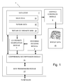
- Figure 1 is a schematic block diagram of a computer system 1 incorporating a co-ordinate modification module 3 which as will be described enables improved representations of texture rendered wire mesh models to be created which permit greater levels of compression of such models.
- the computer system 1 also comprises: an encoding/decoding module 5, a data store 7, a graphics conversion module 9, a compression/decompression module 11 and a data transmission module 13.
- the data store 7 is arranged to store data comprising: mesh data 15 which defines the geometry and connectivity of triangle mesh surface; texture data 17 which in this embodiment comprises a 2D image of texture to be rendered onto the surface defined by the mesh data 15; and texture co-ordinate data 19 which define a mapping between vertices of the surface defined by the mesh data 15 and positions within the texture data to identify portions of the texture data 17 to be applied to each triangle in the triangle mesh surface.
- the graphics conversion module 7 is arranged to process the data 15-19 stored in the data store 7 and generate a display data 21 being a visual representation of the wire mesh model rendered using the texture data 17 and the texture co-ordinate data 19.
- Detailed model data can be of a significant size. For that reason if such data is to be transmitted to another computer via a communications network or stored, the data needs to be compressed. In this embodiment this is achieved by the encoding/decoding module 5 and compression/decompression module 11 which in this embodiment comprise a conventional PRC-HCT encoding module and a conventional compression module for compressing data using the Deflate algorithm in zLib. This compressed data can then be transmitted to another computer or to storage by the data transmission module 13.
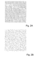
- Figures 2 and 3 illustrate the effect of such displacement errors on the representation of an exemplary wire mesh model and an exemplary checkerboard texture render pattern.
- Figure 2A is a plan view of an exemplary wire mesh model comprising a regular grid defining a flat surface.
- Figure 2B is a plan view of a reconstruction of the exemplary wire mesh model of Figure 2A from compressed data illustrating the introduction of small displacement errors such as arise in the encoding and compression processes. As can be seen in this illustration encoding introduces minor errors into the geometry data for the grid.
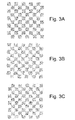
- Figure 3A is a representation of a rendering of a checker board pattern onto the surface of Figure 2A
- Figure 3B is a representation of the rendering of the same checker board pattern of Figure 3A on the surface of Figure 2B .
- the present invention identifies the spatial errors arising during mesh compression and encoding and then utilizes the identified errors to adjust the texture co-ordinate data 19 to be associated with a compressed model to compensate for such errors.
- Such correction may either be utilized to achieve a more accurate and faithful rendition of the original model or alternatively the modified texture co-ordinates may be subjected to truncation and approximation enabling higher rates of data compression to be achieved.
- original uncompressed texture co-ordinates might be represented by a pair of 4-byte (32-bit) floating point precision integers, they might be truncated to a pair of 2-byte (16-bit) integers, resulting in substantially reduced storage and transmission costs.
- any such truncation approximation of uv texture co-ordinates would be additive to errors from spatial distortion.
- processing the texture co-ordinates in advance to correct for the errors arising due to spatial distortions arising from mesh encoding and compression greater levels of truncation can be permitted for a permitted level of error.
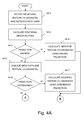
- the co-ordinate modification module 3 is invoked when the encoding/decoding module 5 has finished processing the mesh data 15.
- the co-ordinate modification module 3 receives (s4-1) mesh data 15 and texture co-ordinate data 19 from the data store 7 and modified mesh data from the encoding/decoding module 5.
- Both the original mesh data 15 received from the data store 7 and the modified mesh data received from the encoding/decoding module 5 comprise data defining the 3D locations of vertices in the wire mesh being modeled.
- the original mesh data 15 received from the data store 7 will identify the positions of the vertices as they are recorded in the original mesh data 15.
- the modified mesh data received from the encoding/decoding module 5 will identify the locations of the vertices as they are represented in model data which is to be reconstructed from data output by the data transmission module 13. As noted above due to approximations in the encoding process the locations associated with corresponding vertices in the original and modified mesh data will differ slightly from one another.
- the co-ordinate modification module 3 then (s4-2) proceeds to calculate a set of positional error correction vectors.
- the co-ordinate modification module 3 proceeds to compare the 3D co-ordinates for each vertex in the wire mesh model as defined in the original mesh data 15 with the 3D co-ordinates for the corresponding vertex in the modified mesh data which is to be output by the data transmission module 13. The co-ordinate modification module 3 then records an error vector for each vertex recording the difference in position for the vertex as defined by the original mesh data 15 and the position for the vertex to be output by the data transmission module 13.
- the co-ordinate modification module 3 When error vectors have been determined for all of the vertices in the mesh being processed, the co-ordinate modification module 3 then (s4-3) checks whether the projection linking positions in 3D space and positions of point in the texture data 17 are known. If this is the case the co-ordinate modification module 3 then proceeds to utilize the projection and the error vectors to modify the texture co-ordinate data 19 received from the data store 7 so that the texture co-ordinate data 19 identify parts of the texture data 17 corresponding to the actual positions of vertices as identified by data output by the data transmission module 13 rather than the positions of vertices identified by the mesh data 15 in the data store 7.
- the 3D position of a second point in a wire mesh model P 2 is encoded by storing data defining the vector connecting a previously encoded point P 1 with the point being encoded P 2 (i.e. data recording the vector P 2 - P 1 is recorded).
- data for a modified vector is P' 2 - P 1 may be encoded in the data which is finally output with the result that the point is encoded as being at position P' 2 rather than position P 2 .
- point P 2 will be associated with a position T(u,v) in the image defined by the texture data 17.
- the output mesh data associates the vertex being encoded with P' 2 rather than position P 2
- the correct texture co-ordinates for the position actually being encoded will be at a different location T'(u,v) in the image defined by the texture data 17 with the location of T'(u,v) being offset from T(u,v) by a texture co-ordinate error vector ⁇ .
- the correction vector ⁇ in the image plane can be determined directly from the error vector ⁇ in 3D space by noting the projection of the error vector ⁇ into the image plane.
- the texture co-ordinates for the actual position identified by the output mesh data can then be determined by applying the correction ⁇ in the image plane to the original texture mesh co-ordinates T(u,v) so that texture applied to the point corresponding to texture at position T'(u,v) rather than T(u,v).
- Texture may be projected onto a surface in a vast number of ways. However, it is most common that some form of planar projection is used where texture data 17 is effectively projected onto a model in the manner of a slide projector onto a 3D surface from a particular direction with other more complex projections such as spherical or distorted projections being less common. It is therefore often possible if the projection in question is not known to determine a projection by (s4-5) analyzing the relationships between the 3D positions of vertices in the mesh data 15 and the u,v positions identified by texture co-ordinates 17 received from the data store 7. This can be achieved by analyzing the manner in which u,v co-ordinates vary depending upon variations in 3D position.
- a frequently used projection in the case of an elevation mesh where mesh vertices are arranged on a regular 2D grid is to use a projection where texture data 17 is effectively projected onto a surface from a plane lying parallel to the x and y axes.
- the existence of such a projection can be identified by considering the manner in which u,v positions vary dependent upon variations in x,y,z position data. In such an example, it would be possible to determine that for example u values varied monotonically with variations in x co-ordinate, v values varied monotonically with variations in y co-ordinate and no pattern of variation in z co-ordinate was apparent. Whereas a simple planar projection in the manner described is particularly easy to identify it will be appreciated that by comparing identified correlations between changes in 3D position and u,v texture co-ordinates other more complex projections can be identified.
- modified texture co-ordinates can then (s4-7) be calculated in a similar manner as has previously been described (s4-4) using the calculated error vectors ⁇ and the determined projection.
- Figure 4B illustrates the processing undertaken by the co-ordinate modification module 3 in this embodiment to determine an estimate.
- the co-ordinate modification module 3 determines an estimate of the corrections to be made based on the fact that the texture applied to individual triangles in a triangle mesh model are identified by the texture co-ordinates associated with the vertices of each of the triangles in the mesh.
- the co-ordinate modification module 3 selects a first triangle for processing and then selects (s4-9) an initial vertex from that triangle.
- the actual 3D position of the selected vertex as identified in the modified mesh data received from the encoding/decoding module 5 is then (s4-1 0) considered.
- the co-ordinate modification module 3 identifies the point in the texture data 17 corresponding to the output vertex location and records co-ordinate data for that point as a potential texture co-ordinate data for the vertex.
- the co-ordinate modification module 3 determines a projection of the output of the vertex being considered onto the plane containing the original locations of vertices of the triangle currently being processed.
- the triangle being processed is associated with original mesh data 15 which identifies the vertices of the triangle as being at points P 1 , P 2 , and P 3
- these basis vectors are P 2 -P 1 , P 3 -P 1 and ( P 2 -P 1 ) x( P 3 -P 1 ) , where the origin for the basis vectors is chosen from a vertex of the triangle, typically as P 1 .
- a projection of a vertex as identified in output data on to the plane containing points P 1 , P 2 , and P 3 can then be made by representing the position of the vertex in the co-ordinate system of the three basis vectors and then setting the co-ordinate value for the final basis vector ( P 2 -P 1 ) x ( P 3 -P 1 ) to zero. This will then identify a point in the plane containing the triangle P 1 , P 2 , and P 3 .
- Estimated texture co-ordinates for the projection of the output position of a vertex into the plane containing the triangle being processed can then be determined by considering the mapping of texture co-ordinates to the plane containing points P 1 , P 2 , and P 3 defined by the original texture co-ordinate data 19 associated with the triangle being processed.
- the co-ordinate modification module 3 then checks (s4-11) whether texture co-ordinates for the actual positions for all three vertices of the triangle currently being process have been determined. If this is not the case, the next vertex in the triangle being processed is selected (s4-12) and estimated texture co-ordinates for that vertex are determined (s4-10).
- the co-ordinate modification module 3 determines (s4-11) that estimated texture co-ordinates for all three vertices in a triangle have been calculated, the co-ordinate modification module 3 then (s4-13) checks whether all of the triangles on the triangle mesh have been processed.
- the co-ordinate modification module 3 then proceeds (s4-9-s4-12) to generate estimated texture co-ordinates for all three vertices in the newly selected triangle.
- the co-ordinate modification module 3 determines (s4-13) that all the triangles in a triangle mesh have been processed, a set of estimated texture co-ordinates will be stored for each vertex in the mesh. This will comprise a pair of estimated texture co-ordinates for a vertex for each triangle in the triangle mesh containing that vertex. Thus for example if a particular vertex is shared by three triangles, three sets of estimated texture co-ordinates will be stored.
- the co-ordinate modification module 3 determines a final estimated modified texture co-ordinate for each vertex by, in this embodiment, taking an average of the estimated u,v co-ordinates determined for that vertex.
- the co-ordinate modification module 3 will have calculated a modified set of texture co-ordinate data 19 which accounts for the introduction of spatial errors in the encoding a compression of the mesh by the encoding/decoding module 5 and the compression module 11.
- These modified co-ordinates may have been determined based on a known relationship between texture render data 17 and positions in 3D model space (s4-4).
- modified texture co-ordinates may be based on the identification of a relationship between texture render data 17 and positions in 3D model space derived from analysis of mesh data 15 and unmodified texture co-ordinate data 19 (s4-7) or alternatively they may be based on estimates of modified texture co-ordinates based on the projection of points to planes containing triangles in the triangle mesh (s4-8 -s4-15).
- the co-ordinate modification module 3 determines whether these modified texture co-ordinates are to be utilized to reduce the appearance of distortion of a texture rendered mesh or whether the modified texture co-ordinates are to be utilized to achieve improved level of data compression.
- the co-ordinate modification module 3 determines that the modified texture co-ordinates are to be utilized to reduce the appearance of distortion of a texture rendered mesh
- the modified texture co-ordinates are output (s4-17) to the compression/ decompression module 11 for compression using conventional techniques before compressed mesh data 15, texture data 17 and texture co-ordinate data 19 are passed to the data transmission module 13.
- the modification of texture co-ordinates in this way removes some of the errors which appear due to the encoding and compression of a mesh surface and hence improve the fidelity of a surface being rendered.
- the co-ordinate modification module 3 determines that the modified texture co-ordinates are to be utilized to achieve improved level of data compression, the co-ordinate modification module 3 proceeds (s4-18) to reduce the volume of the modified texture co-ordinates by truncating each item of co-ordinate data prior to sending the truncated modified texture co-ordinates to the compression/decompression module 11 for compression and dispatch by the data transition module 13.
- an error value representative of the apparent distortion of a model was determined. More specifically to evaluate the system, two dimensional distance values were calculated for the distance in u,v space between the exact corrected texture co-ordinates calculated for each vertex of an exemplary model and the position in u,v, coordinate space identified by either unmodified texture co-ordinate data or a position identified after texture co-ordinates had been truncated to a certain degree.
- An overall error value for the exemplary model was then calculated by summing the calculated distance measures for all of the vertices of the model resulting in the following: Total error value Original texture co-ordinates with 23 bits after the binary radix point 14.961 Modified texture co-ordinates with 23 bits after the binary radix point 0.046 Modified texture co-ordinates truncated to 18 bits after the binary radix point 0.066 Modified texture co-ordinates truncated to 14 bits after the binary radix point 0.753 Modified texture co-ordinates truncated to 10 bits after the binary radix point 12.057 Modified texture co-ordinates truncated to 9 bits after the binary radix point 24.079
- texture co-ordinates can be truncated to around 9-10 bits after the binary radix point before errors similar to those which arise in conventional unprocessed data re-appear.
- texture co-ordinate data is stored as a pair of 4 byte, 32-bit floating point precision integers for each vertex in a triangle mesh.
- Such co-ordinate data can account for around three quarters of the data needed to represent a texture rendered wire mesh model. Truncation of such data can result in significant levels of data compression. Thus for example in the case of an exemplary mesh the following were achieved.
- File size after compression Error Original data truncated to 15 bits after the binary radix point 78.2KB 14.98
- the embodiments of the invention described with reference to the drawings comprise computer apparatus and processes performed in computer apparatus, the invention also extends to computer programs, particularly computer programs on or in a carrier, adapted for putting the invention into practice.
- the program may be in the form of source or object code or in any other form suitable for use in the implementation of the processes according to the invention.
- the carrier could be any entity or device capable of carrying the program.
- the carrier may comprise a storage medium, such as a ROM, for example a CD ROM or a semiconductor ROM, or a magnetic recording medium, for example a floppy disc or hard disk.
- a storage medium such as a ROM, for example a CD ROM or a semiconductor ROM, or a magnetic recording medium, for example a floppy disc or hard disk.
- the carrier may be a transmissible carrier such as an electrical or optical signal which may be conveyed via electrical or optical cable or by radio or other means.
- the carrier When a program is embodied in a signal which may be conveyed directly by a cable or other device or means, the carrier may be constituted by such cable or other device or means.
- the carrier may be an integrated circuit in which the program is embedded, the integrated circuit being adapted for performing, or for use in the performance of, the relevant processes.
Abstract
Description
- The present invention relates generally to data compression and particularly to compression of texture rendered wire mesh models.
- Texture-mapped 3D graphics models ordinarily consist of three parts: a geometric mesh component, texture render data, and texture co-ordinate data.
- Typically a geometric mesh component comprises data defining the geometry and connectivity of a plurality of triangles or other polygons which together define a wire mesh surface. Texture render data is typically represented by a 2 dimensional image and texture co-ordinate data comprises set of pairs of uv co-ordinates which define a mapping between vertices on the geometric mesh to the 2D image pixel co-ordinate space. The mapping defined by the texture co-ordinate data enables portions of the 2D image defined by the texture render data to be projected onto individual triangles in the mesh. Normally uv texture co-ordinates are normalized in the range 0.0 - 1.0, covering the image where U defines left-right relative location on the image, and V defines the vertical y location on the image. Therefore uv values (0.5, 0.5) specify the center of the image. uv texture co-ordinates are usually specified in single precision 32-bit floating point representation.
- A triangle mesh representation of a complex, three-dimensional object requires a large volume of data. However, the communication lines through which such data may be transferred over the Internet or other networks typically have a limited average rate of data transfer, commonly referred to as bandwidth. Therefore, it is important to compress data objects as best possible before transfer. Similar issues arise with the storage of data representing complex texture rendered surfaces. The better the compression method which is used, the more data can be transferred in a given amount of time or the greater amount of data which can be stored for a given resource.
- There are well-known techniques for compressing 2D image data such as is used to represent texture data. Techniques include run-length encoding and color quantization, such as are used in JPEG, and PNG image standards.
- Similarly there are known 3D polygon mesh compression techniques such as those disclosed in "Highly Compressed Tessellation (PRC-HCT)" in ISO24517-1:2008 PDF/E SC2N570-PRC-WD.pdf (21 July 2009 Edition) available for download from http://pdf.editme.com/PDFE which is hereby incorporated by reference.
- Having reduced the size of a data set for a triangular mesh using the PRC-HCT approach, the processed data can then be further compressed using conventional data compression algorithms such as the Deflate algorithm in zLib written by Jean-Loup Gailly and Mark Adler which is hereby incorporated by reference.
- Greater levels of compression of can be achieved using lossy compression techniques which sacrifice some of the accuracy of the representation of a wire mesh by for example truncation or quantization of the vectors representing a surface to increase the amount of repetition of data and hence increase the susceptibility of data to compression.
- Although, data compression techniques exist, further improvement is desirable, either by obtaining greater compression rates or by reducing the appearance of errors in data compressed to a certain file size.
- In accordance with one aspect of the present invention there is provided a computer implemented method of processing mesh data defining the spatial co-ordinates in a co-ordinate space of vertices of a mesh surface and texture co-ordinate data associating vertices of a mesh surface with locations in an image space of an image to be rendered onto the mesh surface, the method comprising: determining for each of the vertices of a mesh surface represented by mesh data, spatial error vectors identifying the differences in between spatial co-ordinates of vertices of the mesh surface as defined by the mesh data and the spatial co-ordinates of corresponding vertices in a mesh surface generated from an encoded representation of the mesh data; determining a mapping between the co-ordinate space of the mesh data and the image space of an image to be rendered onto the mesh surface; and modifying texture co-ordinate data to associate vertices of the mesh with locations in image space which differ from the locations identified by the unmodified texture co-ordinate data by amounts corresponding to a projection of the determined spatial error vector associated with a vertex to the image space in accordance with the determined mapping.
- The present invention is particularly applicable to modification of texture co-ordinate data associated with triangle mesh data where such as in PRC-HCT encoding, the encoding of triangles in the mesh comprises generating data defining the relative locations of triangles and rounding data representing said triangles to within a geometric tolerance.
- In some embodiments the mapping between co-ordinate space and image space may be known in advance and the known mapping may be used to modify texture co-ordinate data.
- Where a mapping between co-ordinate space and image space is not known in advance, determining a mapping between a co-ordinate space and an image space may comprise analyzing the spatial co-ordinates of vertices of a mesh surface in a co-ordinate space and the texture co-ordinate data associating vertices of the mesh with locations in an image to be rendered onto the mesh surface to determine a mapping. In such embodiments analyzing the spatial co-ordinates and texture co-ordinates may comprise identifying correlations between variations in spatial co-ordinates of vertices identified by mesh data and image locations associated with said vertices by co-ordinate data to determine a mapping between the co-ordinate space and image space. In such embodiments the identified correlations may be utilized to identify the existence of mappings such as planar mappings between the co-ordinate and image spaces.
- In some embodiments a mapping between co-ordinate space and image space may be determined by for each vertex in a mesh surface: identifying a plane in co-ordinate space containing the vertices of a polygon in the mesh which includes the vertex; determining a projection of the spatial position of a corresponding vertex in a mesh surface generated from an encoded representation of the mesh data to the identified plane; and estimating modified texture co-ordinates for the vertex on the basis of the determined projection to the identified plane and the texture co-ordinates associated with the vertices of the polygon defining the plane.
- In some embodiments estimated modified texture co-ordinates may be determined based on projection to planes for each polygon which includes a vertex and the average of estimated texture co-ordinates may be utilized as modified texture co-ordinates for a vertex.
- In a further aspect the present invention also provides a data processing apparatus comprising: a data store operable to store mesh data defining the spatial co-ordinates of vertices of a mesh surface in a co-ordinate space and texture co-ordinate data associating vertices of the mesh surface with locations in an image space of image to be rendered onto the mesh surface; and a co-ordinate modification module operable to: determine spatial error vectors identifying the differences between spatial co-ordinates of vertices of the mesh surface as defined by stored mesh data and the spatial co-ordinates of corresponding vertices in a mesh surface generated from an encoded representation of the mesh data; determine a mapping between the co-ordinate space of the mesh data and the image space of an image to be rendered onto the mesh surface; and modify stored texture co-ordinate data to associate vertices of a mesh defined by mesh data stored in the data store with locations in image space of an image to be rendered onto the mesh which differ from the locations identified by the unmodified texture co-ordinate data by amounts corresponding to the projection of the determined spatial error vector associated with a vertex to the image space in accordance with the determined mapping between the co-ordinate space and the image space.
- Such a data processing apparatus may additionally comprise an encoding module operable to encode triangle mesh data wherein the encoding of triangles in the mesh comprises generating data defining the relative locations of triangles and rounding data representing said triangles to within a geometric tolerance and a data compression module operable to compress encoded triangle mesh data generated by the encoding module and modified texture co-ordinate data output by the co-ordinate modification module.
- In a further aspect there is also provided a non-transient computer readable medium storing computer implementable instructions which when interpreted by a programmable computer cause the computer to become configured as a data processing apparatus comprising: a data store operable to store mesh data defining the spatial co-ordinates of vertices of a mesh surface in a co-ordinate space and texture co-ordinate data associating vertices of the mesh surface with locations in an image to be rendered onto the mesh surface; and a co-ordinate modification module operable to: determine spatial error vectors identifying the differences between spatial co-ordinates of vertices of the mesh surface as defined by stored mesh data and the spatial co-ordinates of corresponding vertices in a mesh surface generated from an encoded representation of the mesh data; determine a mapping between the co-ordinate space of the mesh data and the image space of an image to be rendered onto the mesh surface; and modify stored texture co-ordinate data to associate vertices of a mesh defined by mesh data stored in the data store with locations in image space of an image to be rendered onto the mesh which differ from the locations identified by the unmodified texture co-ordinate data by amounts corresponding to the projection of the determined spatial error vector associated with a vertex to the image space in accordance with the determined mapping between the co-ordinate space and the image space.
- Embodiments of the present invention will now be described with reference to the accompanying drawings in which:
-
Figure 1 is a schematic block diagram of computer system incorporating a co-ordinate modification module in accordance with an embodiment of the present invention; -
Figure 2A is a plan view of an exemplary wire mesh model; -
Figure 2B is a plan view of a reconstruction of the exemplary wire mesh model ofFigure 2A from compressed data illustrating the introduction of errors which arise in encoding and compression processes; -
Figure 3A is a representation of a rendering of a checkerboard pattern onto the surface ofFigure 2A ; -
Figure 3B is a representation of the rendering of the checkerboard pattern ofFigure 3A on the surface ofFigure 2B ; -
Figure 3C is a representation of the checkerboard pattern ofFigure 3A on the surface ofFigure 2B using a modified set of texture co-ordinates; -
Figures 4A ,4B and4C are a flow diagram of the processing of the co-ordinate modification module ofFigure 1 to determine a set of modified texture co-ordinates; and -
Figure 5 is a schematic diagram for explaining the relationships between spatial errors arising when encoding mesh data and modified texture co-ordinates. -
Figure 1 is a schematic block diagram of acomputer system 1 incorporating aco-ordinate modification module 3 which as will be described enables improved representations of texture rendered wire mesh models to be created which permit greater levels of compression of such models. - In addition to the
co-ordinate modification module 3, thecomputer system 1 also comprises: an encoding/decoding module 5, adata store 7, agraphics conversion module 9, a compression/decompression module 11 and adata transmission module 13. - The
data store 7 is arranged to store data comprising:mesh data 15 which defines the geometry and connectivity of triangle mesh surface;texture data 17 which in this embodiment comprises a 2D image of texture to be rendered onto the surface defined by themesh data 15; and texture co-ordinatedata 19 which define a mapping between vertices of the surface defined by themesh data 15 and positions within the texture data to identify portions of thetexture data 17 to be applied to each triangle in the triangle mesh surface. - The
graphics conversion module 7 is arranged to process the data 15-19 stored in thedata store 7 and generate adisplay data 21 being a visual representation of the wire mesh model rendered using thetexture data 17 and the texture co-ordinatedata 19. - Detailed model data can be of a significant size. For that reason if such data is to be transmitted to another computer via a communications network or stored, the data needs to be compressed. In this embodiment this is achieved by the encoding/
decoding module 5 and compression/decompression module 11 which in this embodiment comprise a conventional PRC-HCT encoding module and a conventional compression module for compressing data using the Deflate algorithm in zLib. This compressed data can then be transmitted to another computer or to storage by thedata transmission module 13. - During the PRC-HCT mesh compression of triangle data structures undertaken by the encoding/
decoding module 5, digital representations of 3D shapes are represented by tessellated triangle faces in a geometric mesh, or triangle mesh. This triangle mesh is processed where successive adjacent triangles are stored in a binary edge tree, by adding a relative vector between the next non-stored point and the mid-point of the shared edge, to describe the next neighbor triangle. This vector is then quantized, rounded to suitable reduced precision numerical value storage, within a geometric tolerance of the original vertex position. Such tolerance based geometric position reduction introduces small 3D displacement errors on the geometric surface. -
Figures 2 and3 illustrate the effect of such displacement errors on the representation of an exemplary wire mesh model and an exemplary checkerboard texture render pattern. -
Figure 2A is a plan view of an exemplary wire mesh model comprising a regular grid defining a flat surface. -
Figure 2B is a plan view of a reconstruction of the exemplary wire mesh model ofFigure 2A from compressed data illustrating the introduction of small displacement errors such as arise in the encoding and compression processes. As can be seen in this illustration encoding introduces minor errors into the geometry data for the grid. - The effect of such errors on the appearance of a texture rendered wire mesh model is illustrated in
Figure 3A and 3B . -
Figure 3A is a representation of a rendering of a checker board pattern onto the surface ofFigure 2A , whereasFigure 3B is a representation of the rendering of the same checker board pattern ofFigure 3A on the surface ofFigure 2B . - As can be seen from
Figures 3A and 3B the effect of the distortions of the wire mesh grid which arise from the encoding process cause corresponding distortions to appear in a rendering of an image. Thus for example, comparingFigures 2A, 2B ,3A and 3B , errors in the encoding of a wire mesh result in the regular grid pattern ofFigure 3A becoming distorted as is shown inFig 3B when it is rendered onto the surface ofFig 2B . - The applicants have appreciated that the identification of the spatial errors which arise in the encoding/compression process provide an opportunity to increase the fidelity of model representation or alternatively to obtain further reductions in the data required to represent a texture rendered wire mesh model.
- More specifically, as will be explained, the present invention identifies the spatial errors arising during mesh compression and encoding and then utilizes the identified errors to adjust the texture co-ordinate
data 19 to be associated with a compressed model to compensate for such errors. - Thus for example, in the case of the examples of
Figures 2 and3 , the effect of such modification would be to modify the appearance of the texture rendered image ofFig 3B to become the representation ofFigure 3C . As can be seen inFigure 3C , modifying the texture co-ordinates restores most of the regular appearance of the original image ofFigure 3A . - Such correction may either be utilized to achieve a more accurate and faithful rendition of the original model or alternatively the modified texture co-ordinates may be subjected to truncation and approximation enabling higher rates of data compression to be achieved.
- Thus for example, whereas original uncompressed texture co-ordinates might be represented by a pair of 4-byte (32-bit) floating point precision integers, they might be truncated to a pair of 2-byte (16-bit) integers, resulting in substantially reduced storage and transmission costs. Ordinarily, any such truncation approximation of uv texture co-ordinates would be additive to errors from spatial distortion. However, by processing the texture co-ordinates in advance to correct for the errors arising due to spatial distortions arising from mesh encoding and compression greater levels of truncation can be permitted for a permitted level of error.
- The processing undertaken by the co-ordinate
modification module 3 will now be described in detail with reference toFigures 4A-C and5 . - Turning first to
Figure 4A , in this embodiment, the co-ordinatemodification module 3 is invoked when the encoding/decoding module 5 has finished processing themesh data 15. When invoked, as an initial step (s4-1) the co-ordinatemodification module 3 receives (s4-1)mesh data 15 and texture co-ordinatedata 19 from thedata store 7 and modified mesh data from the encoding/decoding module 5. Both theoriginal mesh data 15 received from thedata store 7 and the modified mesh data received from the encoding/decoding module 5 comprise data defining the 3D locations of vertices in the wire mesh being modeled. Theoriginal mesh data 15 received from thedata store 7 will identify the positions of the vertices as they are recorded in theoriginal mesh data 15. The modified mesh data received from the encoding/decoding module 5 will identify the locations of the vertices as they are represented in model data which is to be reconstructed from data output by thedata transmission module 13. As noted above due to approximations in the encoding process the locations associated with corresponding vertices in the original and modified mesh data will differ slightly from one another. - When data has been received, the co-ordinate
modification module 3 then (s4-2) proceeds to calculate a set of positional error correction vectors. - More specifically, the co-ordinate
modification module 3 proceeds to compare the 3D co-ordinates for each vertex in the wire mesh model as defined in theoriginal mesh data 15 with the 3D co-ordinates for the corresponding vertex in the modified mesh data which is to be output by thedata transmission module 13. The co-ordinatemodification module 3 then records an error vector for each vertex recording the difference in position for the vertex as defined by theoriginal mesh data 15 and the position for the vertex to be output by thedata transmission module 13. - When error vectors have been determined for all of the vertices in the mesh being processed, the co-ordinate
modification module 3 then (s4-3) checks whether the projection linking positions in 3D space and positions of point in thetexture data 17 are known. If this is the case the co-ordinatemodification module 3 then proceeds to utilize the projection and the error vectors to modify the texture co-ordinatedata 19 received from thedata store 7 so that the texture co-ordinatedata 19 identify parts of thetexture data 17 corresponding to the actual positions of vertices as identified by data output by thedata transmission module 13 rather than the positions of vertices identified by themesh data 15 in thedata store 7. - As shown in
Figure 5 , in conventional PRC-HRT encoding, the 3D position of a second point in a wire mesh model P2 is encoded by storing data defining the vector connecting a previously encoded point P1 with the point being encoded P2 (i.e. data recording the vector P2 - P1 is recorded). However, as a result of truncation approximation or other processing, frequently rather than storing data for the vector P2 - P1, data for a modified vector is P'2 - P1 may be encoded in the data which is finally output with the result that the point is encoded as being at position P'2 rather than position P2. By comparing the actually encoded positions for vertices in a wire mesh with the positions as identified in output data, error vector ε identifying the errors can be identified. - In the original texture co-ordinate
data 19, point P2 will be associated with a position T(u,v) in the image defined by thetexture data 17. However as the output mesh data associates the vertex being encoded with P'2 rather than position P2 , the correct texture co-ordinates for the position actually being encoded will be at a different location T'(u,v) in the image defined by thetexture data 17 with the location of T'(u,v) being offset from T(u,v) by a texture co-ordinate error vector τ . If the relationships between the image plane containing thetexture data 17 and the 3D dimensional space containing the positions of vertices in known then the correction vector τ in the image plane can be determined directly from the error vector ε in 3D space by noting the projection of the error vector ε into the image plane. The texture co-ordinates for the actual position identified by the output mesh data can then be determined by applying the correction τ in the image plane to the original texture mesh co-ordinates T(u,v) so that texture applied to the point corresponding to texture at position T'(u,v) rather than T(u,v). By making appropriate amendments to the texture co-ordinate data for all the vertices, the errors in visual appearance arising due to spatial encoding errors in encoding/compression can largely be eliminated. - It will be appreciated that where the relationship between 3D position space for vertices in the wire mesh and projections to the image plane are known, converting positional error vectors ε into texture co-ordinate corrections τ is relatively straight-forward and hence appropriate amendments can be made for all vertices in a mesh.
- Frequently, however, the details of the mapping between points in 3D space and the image plane of the
texture data 17 are not known in advance. Texture may be projected onto a surface in a vast number of ways. However, it is most common that some form of planar projection is used wheretexture data 17 is effectively projected onto a model in the manner of a slide projector onto a 3D surface from a particular direction with other more complex projections such as spherical or distorted projections being less common. It is therefore often possible if the projection in question is not known to determine a projection by (s4-5) analyzing the relationships between the 3D positions of vertices in themesh data 15 and the u,v positions identified bytexture co-ordinates 17 received from thedata store 7. This can be achieved by analyzing the manner in which u,v co-ordinates vary depending upon variations in 3D position. - Thus for example a frequently used projection in the case of an elevation mesh where mesh vertices are arranged on a regular 2D grid is to use a projection where
texture data 17 is effectively projected onto a surface from a plane lying parallel to the x and y axes. The existence of such a projection can be identified by considering the manner in which u,v positions vary dependent upon variations in x,y,z position data. In such an example, it would be possible to determine that for example u values varied monotonically with variations in x co-ordinate, v values varied monotonically with variations in y co-ordinate and no pattern of variation in z co-ordinate was apparent. Whereas a simple planar projection in the manner described is particularly easy to identify it will be appreciated that by comparing identified correlations between changes in 3D position and u,v texture co-ordinates other more complex projections can be identified. - If the projection connecting the texture co-ordinates can be identified (s4-6), modified texture co-ordinates can then (s4-7) be calculated in a similar manner as has previously been described (s4-4) using the calculated error vectors ε and the determined projection.
- Although analysis of correlations between 3D positions and u,v texture co-ordinates can enable many projections to be identified, such analysis will normally only identify projections which apply globally to an entire surface. Sometimes, in particular where texture co-ordinates encode scientific data, no global projection exists and attempting to identify such a projection will be unsuccessful.
- If analysis (s4-5) of the
mesh data 15 and the texture co-ordinatedata 19 does not reveal (s4-6) a projection to be used an estimation of the appropriate projection needs to be made. -
Figure 4B illustrates the processing undertaken by the co-ordinatemodification module 3 in this embodiment to determine an estimate. In this embodiment, where no global projection can be identified, the co-ordinatemodification module 3 determines an estimate of the corrections to be made based on the fact that the texture applied to individual triangles in a triangle mesh model are identified by the texture co-ordinates associated with the vertices of each of the triangles in the mesh. - In order to determine estimated texture co-ordinates, initially, (s4-8), the co-ordinate
modification module 3 selects a first triangle for processing and then selects (s4-9) an initial vertex from that triangle. - The actual 3D position of the selected vertex as identified in the modified mesh data received from the encoding/
decoding module 5 is then (s4-1 0) considered. - If the 3D co-ordinates for a vertex lie within the triangle plane currently being processed, the co-ordinate
modification module 3 identifies the point in thetexture data 17 corresponding to the output vertex location and records co-ordinate data for that point as a potential texture co-ordinate data for the vertex. - More frequently, the spatial errors introduced during encoding and compression will identify a position which lies outside of the original triangle plane. If this is the case, the co-ordinate
modification module 3 determines a projection of the output of the vertex being considered onto the plane containing the original locations of vertices of the triangle currently being processed. - This can be achieved by re-expressing the 3D co-ordinates of the vertex being processed in terms of a co-ordinate system based on three basis vectors. Where the triangle being processed is associated with
original mesh data 15 which identifies the vertices of the triangle as being at points P1, P2, and P3, these basis vectors are P2-P1, P3-P1 and (P2-P1 ) x( P3-P1 ), where the origin for the basis vectors is chosen from a vertex of the triangle, typically as P1. A projection of a vertex as identified in output data on to the plane containing points P1, P2, and P3 can then be made by representing the position of the vertex in the co-ordinate system of the three basis vectors and then setting the co-ordinate value for the final basis vector (P2-P1 ) x (P3-P1 ) to zero. This will then identify a point in the plane containing the triangle P1, P2, and P3. Estimated texture co-ordinates for the projection of the output position of a vertex into the plane containing the triangle being processed can then be determined by considering the mapping of texture co-ordinates to the plane containing points P1, P2, and P3 defined by the original texture co-ordinatedata 19 associated with the triangle being processed. - Having generated estimated texture co-ordinates for a vertex, the co-ordinate
modification module 3 then checks (s4-11) whether texture co-ordinates for the actual positions for all three vertices of the triangle currently being process have been determined. If this is not the case, the next vertex in the triangle being processed is selected (s4-12) and estimated texture co-ordinates for that vertex are determined (s4-10). - When the co-ordinate
modification module 3 determines (s4-11) that estimated texture co-ordinates for all three vertices in a triangle have been calculated, the co-ordinatemodification module 3 then (s4-13) checks whether all of the triangles on the triangle mesh have been processed. - If this is not the case, the next triangle in the triangle mesh is selected (s4-14) and then the co-ordinate
modification module 3 then proceeds (s4-9-s4-12) to generate estimated texture co-ordinates for all three vertices in the newly selected triangle. - When the co-ordinate
modification module 3 determines (s4-13) that all the triangles in a triangle mesh have been processed, a set of estimated texture co-ordinates will be stored for each vertex in the mesh. This will comprise a pair of estimated texture co-ordinates for a vertex for each triangle in the triangle mesh containing that vertex. Thus for example if a particular vertex is shared by three triangles, three sets of estimated texture co-ordinates will be stored. The co-ordinatemodification module 3 then (s4-15) determines a final estimated modified texture co-ordinate for each vertex by, in this embodiment, taking an average of the estimated u,v co-ordinates determined for that vertex. - Where a global projection between 3D space and a texture plane cannot be determined, calculating modified texture co-ordinates in the way described enables an estimate of an appropriate correction to be made. In general the spatial distortions ε which arise from encoding and compressing
mesh data 15 are not very large. It is therefore a reasonable to approximate the projection of spatial distortions by considering the projection of modified points into planes containing original triangle positions and then extrapolating texture co-ordinates for such projections based on the original texture co-ordinates for the original points. Where this is done for each of the triangles which share a vertex, an estimate of texture co-ordinates for a modified point can be made by taking an average of the calculated estimates. Determining such an average by per-component averaging minimizes the sum of squared errors compared with the initial estimates. - Turning to
Figure 4C , having processed themesh data 15 and texture co-ordinatedata 19 from thedata store 7 and modified mesh data from the encoding/decoding module 5, the co-ordinatemodification module 3 will have calculated a modified set of texture co-ordinatedata 19 which accounts for the introduction of spatial errors in the encoding a compression of the mesh by the encoding/decoding module 5 and thecompression module 11. These modified co-ordinates may have been determined based on a known relationship between texture renderdata 17 and positions in 3D model space (s4-4). Alternatively the modified texture co-ordinates may be based on the identification of a relationship between texture renderdata 17 and positions in 3D model space derived from analysis ofmesh data 15 and unmodified texture co-ordinate data 19 (s4-7) or alternatively they may be based on estimates of modified texture co-ordinates based on the projection of points to planes containing triangles in the triangle mesh (s4-8 -s4-15). - Having determined modified texture co-ordinates for all the vertices in a wire mesh model, the co-ordinate
modification module 3 then (s4-16) determines whether these modified texture co-ordinates are to be utilized to reduce the appearance of distortion of a texture rendered mesh or whether the modified texture co-ordinates are to be utilized to achieve improved level of data compression. - If the co-ordinate
modification module 3 determines that the modified texture co-ordinates are to be utilized to reduce the appearance of distortion of a texture rendered mesh, the modified texture co-ordinates are output (s4-17) to the compression/decompression module 11 for compression using conventional techniques before compressedmesh data 15,texture data 17 and texture co-ordinatedata 19 are passed to thedata transmission module 13. As noted above, the modification of texture co-ordinates in this way removes some of the errors which appear due to the encoding and compression of a mesh surface and hence improve the fidelity of a surface being rendered. - If the co-ordinate
modification module 3 determines that the modified texture co-ordinates are to be utilized to achieve improved level of data compression, the co-ordinatemodification module 3 proceeds (s4-18) to reduce the volume of the modified texture co-ordinates by truncating each item of co-ordinate data prior to sending the truncated modified texture co-ordinates to the compression/decompression module 11 for compression and dispatch by thedata transition module 13. - The applicants have appreciated that any errors which occur due to the introduction of spatial errors in the encoding of a wire mesh model and the truncation of texture co-ordinate data are cumulative. As generating modified texture co-ordinates removes most of the errors in appearance which arise due to spatial errors in mesh encoding, this then means that a similar quality of texture rendered wire mesh can be achieved using less accurate representations of the modified u,v texture co-ordinates.
- To evaluate the performance of the system an error value representative of the apparent distortion of a model was determined. More specifically to evaluate the system, two dimensional distance values were calculated for the distance in u,v space between the exact corrected texture co-ordinates calculated for each vertex of an exemplary model and the position in u,v, coordinate space identified by either unmodified texture co-ordinate data or a position identified after texture co-ordinates had been truncated to a certain degree. An overall error value for the exemplary model was then calculated by summing the calculated distance measures for all of the vertices of the model resulting in the following:
Total error value Original texture co-ordinates with 23 bits after the binary radix point 14.961 Modified texture co-ordinates with 23 bits after the binary radix point 0.046 Modified texture co-ordinates truncated to 18 bits after the binary radix point 0.066 Modified texture co-ordinates truncated to 14 bits after the binary radix point 0.753 Modified texture co-ordinates truncated to 10 bits after the binary radix point 12.057 Modified texture co-ordinates truncated to 9 bits after the binary radix point 24.079 - As can be seen from the above, modifying texture co-ordinates to correct for spatial encoding errors substantially reduces the appearance of such errors and hence reduces error levels from almost 15 to less than 0.05. As would be expected truncating modified texture co-ordinates increases the appearance of error. However, texture co-ordinates can be truncated to around 9-10 bits after the binary radix point before errors similar to those which arise in conventional unprocessed data re-appear.
- Typically texture co-ordinate data is stored as a pair of 4 byte, 32-bit floating point precision integers for each vertex in a triangle mesh. Such co-ordinate data can account for around three quarters of the data needed to represent a texture rendered wire mesh model. Truncation of such data can result in significant levels of data compression. Thus for example in the case of an exemplary mesh the following were achieved.
File size after compression Error Original data truncated to 15 bits after the binary radix point 78.2KB 14.98 Modified texture co-ordinates truncated to 15 bits after the binary radix point 78.5KB 0.38 Modified texture co-ordinates truncated to 10 bits after the binary radix point 62.9KB 12.06 - Thus as can be seen, utilizing modified texture co-ordinates in the manner discussed and truncating texture co-ordinates to 15 bits after the binary radix point largely removes errors in appearance (error reduced from 14.98 to 0.38) at the cost of a marginally increased file size(78.5KB v 78.2KB). In contrast utilizing modified texture co-ordinates and reducing the numbers of bits after the binary radix point from 23 to 10 results in a slightly more accurate representation than that which is achieve without amending the texture co-ordinates (error reduced from 14.98 to 12.06) and an approximately 20% reduction in file size.
- Although the embodiments of the invention described with reference to the drawings comprise computer apparatus and processes performed in computer apparatus, the invention also extends to computer programs, particularly computer programs on or in a carrier, adapted for putting the invention into practice. The program may be in the form of source or object code or in any other form suitable for use in the implementation of the processes according to the invention. The carrier could be any entity or device capable of carrying the program.
- For example, the carrier may comprise a storage medium, such as a ROM, for example a CD ROM or a semiconductor ROM, or a magnetic recording medium, for example a floppy disc or hard disk. Further, the carrier may be a transmissible carrier such as an electrical or optical signal which may be conveyed via electrical or optical cable or by radio or other means.
- When a program is embodied in a signal which may be conveyed directly by a cable or other device or means, the carrier may be constituted by such cable or other device or means.
- Alternatively, the carrier may be an integrated circuit in which the program is embedded, the integrated circuit being adapted for performing, or for use in the performance of, the relevant processes.
Claims (16)
- A computer implemented method of processing mesh data defining the spatial co-ordinates in a co-ordinate space of vertices of a mesh surface and texture co-ordinate data associating vertices of a mesh surface with locations in an image space of an image to be rendered onto the mesh surface, the method comprising:determining for each of the vertices of a mesh surface represented by mesh data, spatial error vectors identifying the differences in between spatial co-ordinates of vertices of the mesh surface as defined by the mesh data and the spatial co-ordinates of corresponding vertices in a mesh surface generated from an encoded representation of the mesh data;determining a mapping between the co-ordinate space of the mesh data and the image space of an image to be rendered onto the mesh surface; andmodifying texture co-ordinate data to associate vertices of the mesh with locations in image space which differ from the locations identified by the unmodified texture co-ordinate data by amounts corresponding to a projection of the determined spatial error vector associated with a vertex to the image space in accordance with the determined mapping.
- The method of claim 1 wherein determining a mapping between co-ordinate space and image space comprises identifying a known mapping between the co-ordinate space of the mesh data and locations in an image to be rendered onto a mesh surface.
- The method of claim 1 wherein determining a mapping between co-ordinate space and the image space comprises analyzing the spatial co-ordinates of vertices of a mesh surface in a co-ordinate space and the texture co-ordinate data associating vertices of the mesh with locations in an image to be rendered onto the mesh surface to determine a mapping between the co-ordinate space of the mesh data and the image space of an image to be rendered onto the mesh surface.
- The method of claim 3 wherein the analysis of spatial co-ordinates and texture co-ordinate data comprises identifying correlations between variations in spatial co-ordinates of vertices identified by mesh data and image locations associated with said vertices by co-ordinate data to determine a mapping between the co-ordinate space and image space.
- The method of claim 4 wherein said mapping comprises a planar mapping and the analysis of spatial co-ordinates and texture co-ordinate data comprises utilizing said identified correlations to determine said planar mapping.
- The method of claim 1 wherein determining a mapping between co-ordinate space and image space comprises, for each vertex in a mesh surface:identifying a plane in co-ordinate space containing the vertices of a polygon in the mesh which includes the vertex;determining a projection of the spatial position of a corresponding vertex in a mesh surface generated from an encoded representation of the mesh data to the identified plane; andestimating modified texture co-ordinates for the vertex on the basis of the determined projection to the identified plane and the texture co-ordinates associated with the vertices of the polygon defining the plane.
- The method of claim 6 wherein determining a mapping between co-ordinate space of and image space comprises:estimating modified texture co-ordinates for each vertex for each polygon which includes the vertex; andutilizing as modified texture co-ordinates the average texture co-ordinates determined for a vertex.
- The method of claim 1 further comprising truncating the modified texture co-ordinates.
- The method of claim 1 wherein said mesh data comprises triangle mesh data and wherein the encoding of triangles in the mesh comprises generating data defining the relative locations of triangles and rounding data representing said triangles to within a geometric tolerance.
- The method of claim 9 wherein said encoding comprises PRC- HCT encoding.
- A data processing apparatus comprising:a data store operable to store mesh data defining the spatial co-ordinates of vertices of a mesh surface in a co-ordinate space and texture co-ordinate data associating vertices of the mesh surface with locations in an image space of image to be rendered onto the mesh surface; anda co-ordinate modification module operable to:determine spatial error vectors identifying the differences between spatial co-ordinates of vertices of the mesh surface as defined by stored mesh data and the spatial co-ordinates of corresponding vertices in a mesh surface generated from an encoded representation of the mesh data;determine a mapping between the co-ordinate space of the mesh data and the image space of an image to be rendered onto the mesh surface; andmodify stored texture co-ordinate data to associate vertices of a mesh defined by mesh data stored in the data store with locations in image space of an image to be rendered onto the mesh which differ from the locations identified by the unmodified texture co-ordinate data by amounts corresponding to the projection of the determined spatial error vector associated with a vertex to the image space in accordance with the determined mapping between the co-ordinate space and the image space.
- The data processing apparatus of claim 11 wherein the co-ordinate modification module is operable to implement the computer method of any of Claims 1 to 10.
- The data processing apparatus of claim 11 or claim 12 further comprising an encoding module operable to encode triangle mesh data wherein the encoding of triangles in the mesh comprises generating data defining the relative locations of triangles and rounding data representing said triangles to within a geometric tolerance.
- The data processing apparatus of claim 13 further comprising a data compression module operable to compress encoded triangle mesh data generated by the encoding module and modified texture co-ordinate data output by the co-ordinate modification module.
- A non-transient computer readable medium storing computer implementable instructions which when interpreted by a programmable computer cause the computer to become configured as a data processing apparatus comprising:a data store operable to store mesh data defining the spatial co-ordinates of vertices of a mesh surface in a co-ordinate space and texture co-ordinate data associating vertices of the mesh surface with locations in an image to be rendered onto the mesh surface; anda co-ordinate modification module operable to:determine spatial error vectors identifying the differences between spatial co-ordinates of vertices of the mesh surface as defined by stored mesh data and the spatial co-ordinates of corresponding vertices in a mesh surface generated from an encoded representation of the mesh data;determine a mapping between the co-ordinate space of the mesh data and the image space of an image to be rendered onto the mesh surface; andmodify stored texture co-ordinate data to associate vertices of a mesh defined by mesh data stored in the data store with locations in image space of an image to be rendered onto the mesh which differ from the locations identified by the unmodified texture co-ordinate data by amounts corresponding to the projection of the determined spatial error vector associated with a vertex to the image space in accordance with the determined mapping between the co-ordinate space and the image space.
- The non-transient computer readable medium of claim 15 wherein the co-ordinate modification module is operable to implement the computer method of any of Claims 1 to 10.
Applications Claiming Priority (1)
| Application Number | Priority Date | Filing Date | Title |
|---|---|---|---|
| US13/287,472 US8736603B2 (en) | 2011-11-02 | 2011-11-02 | Compression of texture rendered wire mesh models |
Publications (3)
| Publication Number | Publication Date |
|---|---|
| EP2592596A2 true EP2592596A2 (en) | 2013-05-15 |
| EP2592596A3 EP2592596A3 (en) | 2014-12-24 |
| EP2592596B1 EP2592596B1 (en) | 2020-04-15 |
Family
ID=47278080
Family Applications (1)
| Application Number | Title | Priority Date | Filing Date |
|---|---|---|---|
| EP12188600.6A Active EP2592596B1 (en) | 2011-11-02 | 2012-10-15 | Compression of texture rendered wire mesh models |
Country Status (2)
| Country | Link |
|---|---|
| US (1) | US8736603B2 (en) |
| EP (1) | EP2592596B1 (en) |
Families Citing this family (26)
| Publication number | Priority date | Publication date | Assignee | Title |
|---|---|---|---|---|
| US9251116B2 (en) * | 2011-11-30 | 2016-02-02 | International Business Machines Corporation | Direct interthread communication dataport pack/unpack and load/save |
| EP2805307B1 (en) * | 2012-01-21 | 2024-04-24 | InterDigital VC Holdings, Inc. | Method and apparatus for compressing texture information of three-dimensional (3d) models |
| US20140340393A1 (en) * | 2012-02-03 | 2014-11-20 | Thomson Licensing | System and method for error controllable repetitive structure discovery based compression |
| US20150016742A1 (en) * | 2012-02-20 | 2015-01-15 | Thomson Licensing | Methods for compensating decoding error in three-dimensional models |
| JP6019215B2 (en) * | 2012-04-18 | 2016-11-02 | トムソン ライセンシングThomson Licensing | Vertex correction method and apparatus for rotated three-dimensional (3D) components |
| CN105103192B (en) * | 2013-01-10 | 2018-09-25 | 汤姆逊许可公司 | Method and apparatus for vertex error correction |
| EP4113991A1 (en) * | 2014-09-03 | 2023-01-04 | Nevermind Capital LLC | Methods and apparatus for capturing, streaming and/or playing back content |
| FR3028990B1 (en) * | 2014-11-21 | 2018-01-19 | Institut National Des Sciences Appliquees De Lyon | METHODS OF COMPRESSING AND DECOMPRESSING REPRESENTATIVE DATA OF A DIGITAL THREE DIMENSIONAL OBJECT AND INFORMATION RECORDING MEDIUM CONTAINING THE SAME |
| US9646410B2 (en) | 2015-06-30 | 2017-05-09 | Microsoft Technology Licensing, Llc | Mixed three dimensional scene reconstruction from plural surface models |
| US10163247B2 (en) | 2015-07-14 | 2018-12-25 | Microsoft Technology Licensing, Llc | Context-adaptive allocation of render model resources |
| US9665978B2 (en) * | 2015-07-20 | 2017-05-30 | Microsoft Technology Licensing, Llc | Consistent tessellation via topology-aware surface tracking |
| US10733766B2 (en) | 2016-10-19 | 2020-08-04 | Google, Llc | Methods and apparatus to encode and/or decode normals of geometric representations of surfaces |
| US10313673B2 (en) | 2016-10-19 | 2019-06-04 | Google Llc | Methods and apparatus to encode and/or decode normals of geometric representations of surfaces |
| US9787321B1 (en) | 2016-11-17 | 2017-10-10 | Google Inc. | Point cloud data compression using a space-filling curve |
| US10496336B2 (en) | 2016-11-17 | 2019-12-03 | Google Llc | K-D tree encoding for point clouds using deviations |
| US10430975B2 (en) | 2016-11-17 | 2019-10-01 | Google Llc | Advanced k-D tree encoding for point clouds by most significant axis selection |
| US10950042B2 (en) | 2017-06-02 | 2021-03-16 | Google Llc | Guided traversal in compression of triangular meshes |
| US10553035B2 (en) | 2017-06-02 | 2020-02-04 | Google Llc | Valence based implicit traversal for improved compression of triangular meshes |
| US10650586B2 (en) | 2017-08-10 | 2020-05-12 | Outward, Inc. | Automated mesh generation |
| CN109544668B (en) * | 2017-09-21 | 2022-10-25 | 腾讯科技(深圳)有限公司 | Texture coordinate processing method, terminal device and computer readable storage medium |
| US10417806B2 (en) * | 2018-02-15 | 2019-09-17 | JJK Holdings, LLC | Dynamic local temporal-consistent textured mesh compression |
| US10891758B2 (en) | 2018-07-23 | 2021-01-12 | Google Llc | Geometry encoder |
| CN111773707A (en) * | 2020-08-11 | 2020-10-16 | 网易(杭州)网络有限公司 | Rendering processing method and device, electronic equipment and storage medium |
| CN112365584A (en) * | 2020-11-23 | 2021-02-12 | 浙江凌迪数字科技有限公司 | Method for generating printing effect on three-dimensional garment model |
| US20230222697A1 (en) * | 2022-01-10 | 2023-07-13 | Tencent America LLC | Mesh compression with deduced texture coordinates |
| CN117412058A (en) * | 2022-07-06 | 2024-01-16 | 维沃移动通信有限公司 | Encoding and decoding methods, devices and equipment |
Family Cites Families (15)
| Publication number | Priority date | Publication date | Assignee | Title |
|---|---|---|---|---|
| US5953506A (en) * | 1996-12-17 | 1999-09-14 | Adaptive Media Technologies | Method and apparatus that provides a scalable media delivery system |
| US6208347B1 (en) * | 1997-06-23 | 2001-03-27 | Real-Time Geometry Corporation | System and method for computer modeling of 3D objects and 2D images by mesh constructions that incorporate non-spatial data such as color or texture |
| US6064771A (en) * | 1997-06-23 | 2000-05-16 | Real-Time Geometry Corp. | System and method for asynchronous, adaptive moving picture compression, and decompression |
| EP1086412A4 (en) * | 1998-06-08 | 2008-05-07 | Microsoft Corp | Compression of time-dependent geometry |
| JP4409956B2 (en) * | 2002-03-01 | 2010-02-03 | ティーファイヴ ラブズ リミテッド | Centralized interactive graphical application server |
| US20050168460A1 (en) * | 2002-04-04 | 2005-08-04 | Anshuman Razdan | Three-dimensional digital library system |
| US7436981B2 (en) * | 2005-01-28 | 2008-10-14 | Euclid Discoveries, Llc | Apparatus and method for processing video data |
| DE102004049156B4 (en) * | 2004-10-08 | 2006-07-13 | Fraunhofer-Gesellschaft zur Förderung der angewandten Forschung e.V. | Coding scheme for a temporally variable graphic model representing data stream |
| US7432936B2 (en) * | 2004-12-02 | 2008-10-07 | Avid Technology, Inc. | Texture data anti-aliasing method and apparatus |
| US8207965B2 (en) * | 2006-07-11 | 2012-06-26 | Adobe Systems Incorporated | Rewritable compression of triangulated data |
| WO2008129021A2 (en) * | 2007-04-18 | 2008-10-30 | Gottfried Wilhelm Leibniz Universität Hannover | Scalable compression of time-consistend 3d mesh sequences |
| EP2216750A1 (en) * | 2009-02-06 | 2010-08-11 | Thomson Licensing | Method and apparatus for encoding 3D mesh models, and method and apparatus for decoding encoded 3D mesh models |
| EP2261859A1 (en) * | 2009-06-10 | 2010-12-15 | Thomson Licensing | Method for encoding/decoding a 3D mesh model that comprises one or more components |
| GB201003962D0 (en) * | 2010-03-10 | 2010-04-21 | Tangentix Ltd | Multimedia content delivery system |
| US8416236B1 (en) * | 2012-07-19 | 2013-04-09 | Google Inc. | Calibration of devices used to generate images of a three-dimensional object data model |
-
2011
- 2011-11-02 US US13/287,472 patent/US8736603B2/en active Active
-
2012
- 2012-10-15 EP EP12188600.6A patent/EP2592596B1/en active Active
Non-Patent Citations (1)
| Title |
|---|
| "IS024517-1:2008 PDF/E SC2N570-PRC-WD.pdf", 21 July 2009, article "Highly Compressed Tessellation (PRC-HCT" |
Also Published As
| Publication number | Publication date |
|---|---|
| US20130106834A1 (en) | 2013-05-02 |
| EP2592596A3 (en) | 2014-12-24 |
| EP2592596B1 (en) | 2020-04-15 |
| US8736603B2 (en) | 2014-05-27 |
Similar Documents
| Publication | Publication Date | Title |
|---|---|---|
| EP2592596A2 (en) | Compression of texture rendered wire mesh models | |
| JP6676193B2 (en) | Method for encoding a point cloud representing a scene, an encoder system, and a non-transitory computer-readable recording medium storing a program | |
| EP3275190B1 (en) | Chroma subsampling and gamut reshaping | |
| US9736455B2 (en) | Method and apparatus for downscaling depth data for view plus depth data compression | |
| CN111433821B (en) | Method and apparatus for reconstructing a point cloud representing a 3D object | |
| US7113635B2 (en) | Process for modelling a 3D scene | |
| EP2805307B1 (en) | Method and apparatus for compressing texture information of three-dimensional (3d) models | |
| JP4672735B2 (en) | Texture coordinate encoding and decoding method of 3D mesh information for effective texture mapping | |
| JP7371691B2 (en) | Point cloud encoding using homography transformation | |
| US11711535B2 (en) | Video-based point cloud compression model to world signaling information | |
| JP3790728B2 (en) | Image encoding apparatus, image decoding apparatus and methods thereof | |
| WO2019215388A2 (en) | Method and apparatus for encoding and decoding volumetric video data | |
| CN115315950A (en) | Global scaling of point cloud data | |
| US20230245390A1 (en) | Manhattan layout estimation using geometric and semantic information | |
| US20230162404A1 (en) | Decoding of patch temporal alignment for mesh compression | |
| US20230306641A1 (en) | Mesh geometry coding | |
| WO2023180839A1 (en) | Mesh geometry coding | |
| US20230306683A1 (en) | Mesh patch sub-division | |
| US20230306642A1 (en) | Patch mesh connectivity coding | |
| US20240127489A1 (en) | Efficient mapping coordinate creation and transmission | |
| US20220385941A1 (en) | Volumetric video in web browswer | |
| Maceira et al. | Region-based depth map coding using a 3D scene representation | |
| WO2023180841A1 (en) | Mesh patch sub-division | |
| WO2023180840A1 (en) | Patch mesh connectivity coding | |
| CN117751387A (en) | Face mesh connectivity coding |
Legal Events
| Date | Code | Title | Description |
|---|---|---|---|
| PUAI | Public reference made under article 153(3) epc to a published international application that has entered the european phase |
Free format text: ORIGINAL CODE: 0009012 |
|
| AK | Designated contracting states |
Kind code of ref document: A2 Designated state(s): AL AT BE BG CH CY CZ DE DK EE ES FI FR GB GR HR HU IE IS IT LI LT LU LV MC MK MT NL NO PL PT RO RS SE SI SK SM TR |
|
| AX | Request for extension of the european patent |
Extension state: BA ME |
|
| REG | Reference to a national code |
Ref country code: HK Ref legal event code: DE Ref document number: 1182208 Country of ref document: HK |
|
| PUAL | Search report despatched |
Free format text: ORIGINAL CODE: 0009013 |
|
| RIC1 | Information provided on ipc code assigned before grant |
Ipc: G06T 9/00 20060101AFI20141111BHEP |
|
| AK | Designated contracting states |
Kind code of ref document: A3 Designated state(s): AL AT BE BG CH CY CZ DE DK EE ES FI FR GB GR HR HU IE IS IT LI LT LU LV MC MK MT NL NO PL PT RO RS SE SI SK SM TR |
|
| AX | Request for extension of the european patent |
Extension state: BA ME |
|
| 17P | Request for examination filed |
Effective date: 20150623 |
|
| STAA | Information on the status of an ep patent application or granted ep patent |
Free format text: STATUS: EXAMINATION IS IN PROGRESS |
|
| 17Q | First examination report despatched |
Effective date: 20170524 |
|
| RAP1 | Party data changed (applicant data changed or rights of an application transferred) |
Owner name: VISUAL TECHNOLOGY SERVICES LTD. |
|
| GRAP | Despatch of communication of intention to grant a patent |
Free format text: ORIGINAL CODE: EPIDOSNIGR1 |
|
| STAA | Information on the status of an ep patent application or granted ep patent |
Free format text: STATUS: GRANT OF PATENT IS INTENDED |
|
| INTG | Intention to grant announced |
Effective date: 20191113 |
|
| RIN1 | Information on inventor provided before grant (corrected) |
Inventor name: CURINGTON, IAN |
|
| GRAS | Grant fee paid |
Free format text: ORIGINAL CODE: EPIDOSNIGR3 |
|
| GRAA | (expected) grant |
Free format text: ORIGINAL CODE: 0009210 |
|
| STAA | Information on the status of an ep patent application or granted ep patent |
Free format text: STATUS: THE PATENT HAS BEEN GRANTED |
|
| AK | Designated contracting states |
Kind code of ref document: B1 Designated state(s): AL AT BE BG CH CY CZ DE DK EE ES FI FR GB GR HR HU IE IS IT LI LT LU LV MC MK MT NL NO PL PT RO RS SE SI SK SM TR |
|
| REG | Reference to a national code |
Ref country code: CH Ref legal event code: EP Ref country code: GB Ref legal event code: FG4D |
|
| REG | Reference to a national code |
Ref country code: DE Ref legal event code: R096 Ref document number: 602012069266 Country of ref document: DE |
|
| REG | Reference to a national code |
Ref country code: IE Ref legal event code: FG4D |
|
| REG | Reference to a national code |
Ref country code: AT Ref legal event code: REF Ref document number: 1258173 Country of ref document: AT Kind code of ref document: T Effective date: 20200515 |
|
| REG | Reference to a national code |
Ref country code: SE Ref legal event code: TRGR |
|
| REG | Reference to a national code |
Ref country code: NL Ref legal event code: FP |
|
| REG | Reference to a national code |
Ref country code: CH Ref legal event code: NV Representative=s name: KIRKER AND CIE S.A., CH |
|
| REG | Reference to a national code |
Ref country code: LT Ref legal event code: MG4D |
|
| PG25 | Lapsed in a contracting state [announced via postgrant information from national office to epo] |
Ref country code: PT Free format text: LAPSE BECAUSE OF FAILURE TO SUBMIT A TRANSLATION OF THE DESCRIPTION OR TO PAY THE FEE WITHIN THE PRESCRIBED TIME-LIMIT Effective date: 20200817 Ref country code: NO Free format text: LAPSE BECAUSE OF FAILURE TO SUBMIT A TRANSLATION OF THE DESCRIPTION OR TO PAY THE FEE WITHIN THE PRESCRIBED TIME-LIMIT Effective date: 20200715 Ref country code: IS Free format text: LAPSE BECAUSE OF FAILURE TO SUBMIT A TRANSLATION OF THE DESCRIPTION OR TO PAY THE FEE WITHIN THE PRESCRIBED TIME-LIMIT Effective date: 20200815 Ref country code: FI Free format text: LAPSE BECAUSE OF FAILURE TO SUBMIT A TRANSLATION OF THE DESCRIPTION OR TO PAY THE FEE WITHIN THE PRESCRIBED TIME-LIMIT Effective date: 20200415 Ref country code: LT Free format text: LAPSE BECAUSE OF FAILURE TO SUBMIT A TRANSLATION OF THE DESCRIPTION OR TO PAY THE FEE WITHIN THE PRESCRIBED TIME-LIMIT Effective date: 20200415 Ref country code: GR Free format text: LAPSE BECAUSE OF FAILURE TO SUBMIT A TRANSLATION OF THE DESCRIPTION OR TO PAY THE FEE WITHIN THE PRESCRIBED TIME-LIMIT Effective date: 20200716 |
|
| REG | Reference to a national code |
Ref country code: AT Ref legal event code: MK05 Ref document number: 1258173 Country of ref document: AT Kind code of ref document: T Effective date: 20200415 |
|
| PG25 | Lapsed in a contracting state [announced via postgrant information from national office to epo] |
Ref country code: LV Free format text: LAPSE BECAUSE OF FAILURE TO SUBMIT A TRANSLATION OF THE DESCRIPTION OR TO PAY THE FEE WITHIN THE PRESCRIBED TIME-LIMIT Effective date: 20200415 Ref country code: RS Free format text: LAPSE BECAUSE OF FAILURE TO SUBMIT A TRANSLATION OF THE DESCRIPTION OR TO PAY THE FEE WITHIN THE PRESCRIBED TIME-LIMIT Effective date: 20200415 Ref country code: BG Free format text: LAPSE BECAUSE OF FAILURE TO SUBMIT A TRANSLATION OF THE DESCRIPTION OR TO PAY THE FEE WITHIN THE PRESCRIBED TIME-LIMIT Effective date: 20200715 Ref country code: HR Free format text: LAPSE BECAUSE OF FAILURE TO SUBMIT A TRANSLATION OF THE DESCRIPTION OR TO PAY THE FEE WITHIN THE PRESCRIBED TIME-LIMIT Effective date: 20200415 |
|
| PG25 | Lapsed in a contracting state [announced via postgrant information from national office to epo] |
Ref country code: AL Free format text: LAPSE BECAUSE OF FAILURE TO SUBMIT A TRANSLATION OF THE DESCRIPTION OR TO PAY THE FEE WITHIN THE PRESCRIBED TIME-LIMIT Effective date: 20200415 |
|
| REG | Reference to a national code |
Ref country code: DE Ref legal event code: R097 Ref document number: 602012069266 Country of ref document: DE |
|
| PG25 | Lapsed in a contracting state [announced via postgrant information from national office to epo] |
Ref country code: IT Free format text: LAPSE BECAUSE OF FAILURE TO SUBMIT A TRANSLATION OF THE DESCRIPTION OR TO PAY THE FEE WITHIN THE PRESCRIBED TIME-LIMIT Effective date: 20200415 Ref country code: RO Free format text: LAPSE BECAUSE OF FAILURE TO SUBMIT A TRANSLATION OF THE DESCRIPTION OR TO PAY THE FEE WITHIN THE PRESCRIBED TIME-LIMIT Effective date: 20200415 Ref country code: CZ Free format text: LAPSE BECAUSE OF FAILURE TO SUBMIT A TRANSLATION OF THE DESCRIPTION OR TO PAY THE FEE WITHIN THE PRESCRIBED TIME-LIMIT Effective date: 20200415 Ref country code: EE Free format text: LAPSE BECAUSE OF FAILURE TO SUBMIT A TRANSLATION OF THE DESCRIPTION OR TO PAY THE FEE WITHIN THE PRESCRIBED TIME-LIMIT Effective date: 20200415 Ref country code: SM Free format text: LAPSE BECAUSE OF FAILURE TO SUBMIT A TRANSLATION OF THE DESCRIPTION OR TO PAY THE FEE WITHIN THE PRESCRIBED TIME-LIMIT Effective date: 20200415 Ref country code: AT Free format text: LAPSE BECAUSE OF FAILURE TO SUBMIT A TRANSLATION OF THE DESCRIPTION OR TO PAY THE FEE WITHIN THE PRESCRIBED TIME-LIMIT Effective date: 20200415 Ref country code: DK Free format text: LAPSE BECAUSE OF FAILURE TO SUBMIT A TRANSLATION OF THE DESCRIPTION OR TO PAY THE FEE WITHIN THE PRESCRIBED TIME-LIMIT Effective date: 20200415 Ref country code: ES Free format text: LAPSE BECAUSE OF FAILURE TO SUBMIT A TRANSLATION OF THE DESCRIPTION OR TO PAY THE FEE WITHIN THE PRESCRIBED TIME-LIMIT Effective date: 20200415 |
|
| PLBE | No opposition filed within time limit |
Free format text: ORIGINAL CODE: 0009261 |
|
| STAA | Information on the status of an ep patent application or granted ep patent |
Free format text: STATUS: NO OPPOSITION FILED WITHIN TIME LIMIT |
|
| PG25 | Lapsed in a contracting state [announced via postgrant information from national office to epo] |
Ref country code: PL Free format text: LAPSE BECAUSE OF FAILURE TO SUBMIT A TRANSLATION OF THE DESCRIPTION OR TO PAY THE FEE WITHIN THE PRESCRIBED TIME-LIMIT Effective date: 20200415 Ref country code: SK Free format text: LAPSE BECAUSE OF FAILURE TO SUBMIT A TRANSLATION OF THE DESCRIPTION OR TO PAY THE FEE WITHIN THE PRESCRIBED TIME-LIMIT Effective date: 20200415 |
|
| 26N | No opposition filed |
Effective date: 20210118 |
|
| PG25 | Lapsed in a contracting state [announced via postgrant information from national office to epo] |
Ref country code: SI Free format text: LAPSE BECAUSE OF FAILURE TO SUBMIT A TRANSLATION OF THE DESCRIPTION OR TO PAY THE FEE WITHIN THE PRESCRIBED TIME-LIMIT Effective date: 20200415 |
|
| PG25 | Lapsed in a contracting state [announced via postgrant information from national office to epo] |
Ref country code: LU Free format text: LAPSE BECAUSE OF NON-PAYMENT OF DUE FEES Effective date: 20201015 Ref country code: MC Free format text: LAPSE BECAUSE OF FAILURE TO SUBMIT A TRANSLATION OF THE DESCRIPTION OR TO PAY THE FEE WITHIN THE PRESCRIBED TIME-LIMIT Effective date: 20200415 |
|
| PG25 | Lapsed in a contracting state [announced via postgrant information from national office to epo] |
Ref country code: TR Free format text: LAPSE BECAUSE OF FAILURE TO SUBMIT A TRANSLATION OF THE DESCRIPTION OR TO PAY THE FEE WITHIN THE PRESCRIBED TIME-LIMIT Effective date: 20200415 Ref country code: MT Free format text: LAPSE BECAUSE OF FAILURE TO SUBMIT A TRANSLATION OF THE DESCRIPTION OR TO PAY THE FEE WITHIN THE PRESCRIBED TIME-LIMIT Effective date: 20200415 Ref country code: CY Free format text: LAPSE BECAUSE OF FAILURE TO SUBMIT A TRANSLATION OF THE DESCRIPTION OR TO PAY THE FEE WITHIN THE PRESCRIBED TIME-LIMIT Effective date: 20200415 |
|
| PG25 | Lapsed in a contracting state [announced via postgrant information from national office to epo] |
Ref country code: MK Free format text: LAPSE BECAUSE OF FAILURE TO SUBMIT A TRANSLATION OF THE DESCRIPTION OR TO PAY THE FEE WITHIN THE PRESCRIBED TIME-LIMIT Effective date: 20200415 |
|
| PGFP | Annual fee paid to national office [announced via postgrant information from national office to epo] |
Ref country code: NL Payment date: 20221012 Year of fee payment: 11 Ref country code: FR Payment date: 20221010 Year of fee payment: 11 |
|
| PGFP | Annual fee paid to national office [announced via postgrant information from national office to epo] |
Ref country code: SE Payment date: 20221017 Year of fee payment: 11 Ref country code: IE Payment date: 20221026 Year of fee payment: 11 Ref country code: GB Payment date: 20221007 Year of fee payment: 11 Ref country code: DE Payment date: 20221018 Year of fee payment: 11 |
|
| PGFP | Annual fee paid to national office [announced via postgrant information from national office to epo] |
Ref country code: CH Payment date: 20221014 Year of fee payment: 11 Ref country code: BE Payment date: 20221012 Year of fee payment: 11 |