EP2592440A2 - Elektrodenanordnung für elektromagnetische geophysikalische Unterwasser-Messquellen - Google Patents
Elektrodenanordnung für elektromagnetische geophysikalische Unterwasser-Messquellen Download PDFInfo
- Publication number
- EP2592440A2 EP2592440A2 EP20120191466 EP12191466A EP2592440A2 EP 2592440 A2 EP2592440 A2 EP 2592440A2 EP 20120191466 EP20120191466 EP 20120191466 EP 12191466 A EP12191466 A EP 12191466A EP 2592440 A2 EP2592440 A2 EP 2592440A2
- Authority
- EP
- European Patent Office
- Prior art keywords
- electrode assembly
- carrier body
- electrically conducting
- conducting surfaces
- cable
- Prior art date
- Legal status (The legal status is an assumption and is not a legal conclusion. Google has not performed a legal analysis and makes no representation as to the accuracy of the status listed.)
- Withdrawn
Links
Images



Classifications
-
- G—PHYSICS
- G01—MEASURING; TESTING
- G01V—GEOPHYSICS; GRAVITATIONAL MEASUREMENTS; DETECTING MASSES OR OBJECTS; TAGS
- G01V3/00—Electric or magnetic prospecting or detecting; Measuring magnetic field characteristics of the earth, e.g. declination, deviation
- G01V3/08—Electric or magnetic prospecting or detecting; Measuring magnetic field characteristics of the earth, e.g. declination, deviation operating with magnetic or electric fields produced or modified by objects or geological structures or by detecting devices
- G01V3/083—Controlled source electromagnetic [CSEM] surveying
-
- G—PHYSICS
- G01—MEASURING; TESTING
- G01V—GEOPHYSICS; GRAVITATIONAL MEASUREMENTS; DETECTING MASSES OR OBJECTS; TAGS
- G01V1/00—Seismology; Seismic or acoustic prospecting or detecting
- G01V1/16—Receiving elements for seismic signals; Arrangements or adaptations of receiving elements
- G01V1/20—Arrangements of receiving elements, e.g. geophone pattern
- G01V1/201—Constructional details of seismic cables, e.g. streamers
-
- G—PHYSICS
- G01—MEASURING; TESTING
- G01V—GEOPHYSICS; GRAVITATIONAL MEASUREMENTS; DETECTING MASSES OR OBJECTS; TAGS
- G01V3/00—Electric or magnetic prospecting or detecting; Measuring magnetic field characteristics of the earth, e.g. declination, deviation
- G01V3/08—Electric or magnetic prospecting or detecting; Measuring magnetic field characteristics of the earth, e.g. declination, deviation operating with magnetic or electric fields produced or modified by objects or geological structures or by detecting devices
- G01V3/083—Controlled source electromagnetic [CSEM] surveying
- G01V2003/084—Sources
Definitions
- the present invention relates generally to the field of marine electromagnetic geophysical surveying. More particularly, in one or more embodiments, this invention relates to an electrode assembly for marine electromagnetic geophysical survey sources and associated methods of use, the electrode assembly comprising a carrier body and electrically conducting surfaces longitudinally spaced along the carrier body.
- Marine electromagnetic geophysical surveying is used, among other purposes, to infer spatial distribution of electrical conductivity of rock formations below the bottom of a body of water, such as a lake or ocean.
- the spatial distribution of conductivity is used to assist in determining the presence of hydrocarbon-bearing rock formations in the subsurface, potentially resulting in cost saving by better targeted drilling operations.
- One type of such surveying is known as "controlled source” electromagnetic surveying ("CSEM”), which generally includes inducing a time-varying electromagnetic field in the subsurface formations and measuring one or more parameters related to a response of the subsurface rock formations to the induced electromagnetic field.
- CSEM controlled source electromagnetic surveying
- Electrodes for inducing such electromagnetic fields are generally referred to as electromagnetic “sources” or “transmitters” and include, among other devices, spaced apart electrodes or wire coils disposed along or at the end of a cable.
- the cable is typically towed by a vessel in the body of water.
- Time-varying electric current is imparted across the electrodes to induce a time-varying electric field in the water and subsequently in the subsurface rock formations.
- the electrodes may be large, inflexible structures, such as metal cylinders or tubes. Such cylinders or tubes may be suspended at a selected depth in the water by the use of flotation devices, such as buoys.
- Drawbacks to these types of electrodes include difficulties in handling as these larger, inflexible structures can be difficult to deploy and may exert undesirable stress on the cables, connectors, and flotation devices. Further drawbacks to these types of electrodes include the high power requirements that may be needed to generate the high levels of current that may be imparted across the electrodes, in some instances.
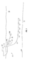
- FIG. 1 illustrates an example embodiment of a marine electromagnetic survey system.
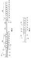
- FIG. 2 illustrates an example embodiment of a source cable comprising two electrode assemblies that each comprise a carrier body and electrically conducting surfaces longitudinally spaced along the carrier body.
- FIG. 3 illustrates an example embodiment of a source cable comprising one electrode assembly that comprises a carrier body and electrically conducting surfaces longitudinally spaced along the carrier body.
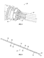
- FIG. 4 illustrates a forward end of an electrode assembly in accordance with example embodiments of the present invention.
- FIG. 5 illustrates an aft end of an electrode assembly in accordance with example embodiments of the present invention.
- FIG. 6 illustrates termination of electrical conductors at a forward termination of an electrode assembly in accordance with example embodiments of the present invention.
- FIG. 7 illustrates parallel connection of electrical conductors to the electrically conducting surfaces of an electrode assembly in accordance with example embodiments of the present invention.
- FIG. 8 illustrates an electrode assembly comprising a central core in accordance with embodiments of the present invention.
- FIG. 9 illustrates an electrode assembly that comprises two or more electrode sections in accordance with example embodiments of the present invention.
- FIGS. 10 and 11 illustrate an electrode assembly in accordance with alternative example embodiments of the present invention.
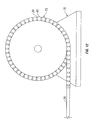
- FIG. 12 illustrates a flexible electrode assembly in accordance with example embodiments of the present invention.
- FIG. 1 illustrates a marine electromagnetic survey system 10 in accordance with embodiments of the present invention.
- the marine electromagnetic survey system 10 may include a sensor cable 12 having thereon at longitudinally spaced apart positions a plurality of sensors 14.
- the sensor cable is shown being towed by a survey vessel 16 moving on the surface of a body of water 18, such as a lake or ocean.
- the sensor cable 12 may alternatively be deployed on or near the water bottom 20 or towed by another vessel (not shown).
- one or more additional sensor cables may be towed behind the survey vessel 16, towed behind another vessel (not shown), or deployed at or near the water bottom 20.
- the invention may also be used with sensor nodes (not shown), for example, static nodes disposed on or near the water bottom 20.
- the types(s) and configurations(s) of the sensors 14 are not intended to limit the scope of the invention.
- the sensors 14 may be used, for example, to measure the electromagnetic response of formations 21 below the water bottom 20 to electromagnetic field(s) imparted by one or more electromagnetic sources, as discussed below.
- the sensors 14 may measure one or more various electric field properties, such as voltage, magnetic field amplitude, and/or magnetic field gradient.
- the survey vessel 16 may include thereon equipment, shown generally at 22 and referred to for convenience as a "recording system,” that may include devices (none shown separately) for navigation, for energizing one or more electromagnetic sources for imparting an electromagnetic field in the formations 21 below the water bottom 20, and/or for recording and processing signals generated by the various sensors 14.
- a recording system may include devices (none shown separately) for navigation, for energizing one or more electromagnetic sources for imparting an electromagnetic field in the formations 21 below the water bottom 20, and/or for recording and processing signals generated by the various sensors 14.
- the marine electromagnetic survey system 10 shown in FIG. 1 further may include an electromagnetic source cable 24 for towing one or more devices for inducing an electromagnetic field in the formations 21 below the water bottom 20.
- the sensor cable 12 may be longer than the source cable 24.
- the sensor cable 12 may have a length that is at least 8 times longer than the source cable 24.
- the sensor cable 12 may have a length in a range of from about 4 kilometers to about 8 kilometers while the source cable 24 may have length in a range of from about 0.5 kilometers to about 2 kilometers.
- the source cable 24 may have a length of about 1 kilometer.
- the source cable 24 may comprise a tow cable 26 coupled (directly or indirectly) to the survey vessel 16 and may include insulated conductors, optical fibers, and a strength member (not shown separately) to, among things, conduct electrical and/or optical signals, conduct electric power, and transmit axial towing force from the survey vessel 16.
- the tow cable 26 is coupled to a pair of electromagnetic source electrodes, such as first and second electrode assemblies 28A, 28B.
- the distance between the first and second electrode assemblies 28A, 28B may be greater than the distance from the survey vessel 16 to the first electrode assembly 28A.
- the distance between the first and second electrode assemblies 28A, 28B may be in a range of from about 400 meters to about 800 meters while the distance from the survey vessel 16 to the first electrode assembly 28A may be in a range of about 50 meters to about 150 meters. In one embodiment, the distance from the survey vessel 16 to the first electrode assembly 28A may be about 100 meters. As illustrated, the first and second electrode assemblies 28A, 28B may be at different depths in the body of water 18 with respect to one another. The aft end (with respect to the towing direction) of the tow cable 26 may be coupled to a forward end (with respect to the towing direction) of the first electrode assembly 28A with the first electrode assembly 28A electrically coupled to the tow cable 26.
- the aft end of the first electrode assembly 28A may be coupled to a spacer cable 30.
- the aft end of the spacer cable 30 may be coupled to a forward end of the second electrode assembly 28B with the second electrode assembly 28B electrically coupled to the tow cable 26.
- the second electrode assembly 28B can be electrically independent from the first electrode assembly 28A.
- the electrode assemblies 28A, 28B may be activated at selected times by an electrical current source (not shown separately) so as to induce an electromagnetic field in the formations 21 below the water bottom 20.
- the electrical current source may be located, for example, in the recording system 22, on the source cable 24, or in other equipment (not shown).
- the current may be, for example, switched direct current (e.g., switching current on, switching current off, reversing current polarity, or sequential switching such as a pseudorandom binary sequence).
- switched direct current e.g., switching current on, switching current off, reversing current polarity, or sequential switching such as a pseudorandom binary sequence.
- the configuration shown in FIG. 1 may induce an electric field in the subsurface formations 21 when the electrode assemblies 28A, 28B are energized by the electric current.
- the type of current used to energize the electrode assemblies 28A, 28B is not limited to the foregoing as the invention is applicable to the use of any desired current waveform.
- the invention is also applicable to both frequency domain (continuous source) and transient induced electromagnetic fields.
- the source cable 24 may include a tow cable 26 that may include, for example, one or more electrical conductors (e.g., first electrical conductor 32, second electrical conductor 33) therein and suitable axial load carrying components (e.g., one or more strength members-not shown) to enable transmission of towing force from the survey vessel (e.g., survey vessel 16 on FIG. 1 ) to the remaining components on the source cable 24.
- the tow cable 26 may be a single cable with two electrical cores, e.g., first electrical conductor 32 and second electrical conductor 33.
- the tow cable 26 is terminated at its aft end by a termination plate 34 that is configured to make suitable electrical and mechanical connections to the first electrode assembly 28A.
- the forward end of the first electrode assembly 28A may be coupled to the aft end of the tow cable 26.
- a forward termination 36 on the first electrode assembly 28A may make mechanical and electrical connection to the termination plate 34 at the aft end of the tow cable 26.
- the first electrode assembly 28A may have a length, for example, in a range of about 10 meters to about 100 meters. In alternative embodiments, the first electrode assembly 28A may have a length in a range of about 12 meters to about 20 meters. Lengths outside this range may also be suitable in some applications. For example, if surveying in a shallow body of water it may be desirable to use a shorter electrode assembly 28A. By way of further example, a longer electrode assembly 28A may be used where a stronger source strength may be desired.
- the first electrode assembly 28A may have a diameter, for example, in a range of about 0.1 meters to about 0.3 meters or, in alternative embodiments, of about 0.1 meters to about 0.2 meters.
- a long, thin electrode assembly 28A, for example, with a long length with respect to the diameter may be desired in accordance with certain embodiments, to provide a reduced contact resistance to water, as compared to other electrodes with the same surface area.
- a smaller diameter electrode assembly 28A will provide a lower drag profile when towed, thereby improving towing performance.
- the forward termination 36 of the first electrode assembly 28A may be coupled to a carrier body 38 on which electrically conducting surfaces 40 are longitudinally spaced.
- the carrier body 38 may be in the form of an elongated support, such as an elongated tube, in accordance with present embodiments.
- the elongated tube of the carrier body 38 may have an oval, circular, triangular, square, pentagonal, or other polygonal-shaped cross section.
- the cross section may comprise one or more concave angles or indentions.
- the carrier body 38 may be made, for example, from a non-conductive material.
- non-conductive materials include thermoplastic polymers, such as polyvinyl chloride, polycarbonate, polyoxymethylene (e.g., Delrin ® acetal resin, available from Dupont Engineering Polymers).
- the carrier body 38 is rigid. In an alternative embodiment, the carrier body 38 is flexible. A carrier body 38 that is flexible may be preferred, in some embodiments, to provide flexibility to the first electrode assembly 28A.
- the carrier body 38 may be sufficiently flexible to permit coiled storage of the electrode assembly 28A on the survey vessel 16 and elongated deployment of the electrode assembly 28A behind the survey vessel 16.
- the configuration of the carrier body 38 is not limited to the foregoing as other structures may be suitable.
- carrier body 38 may be in the form of a central elongated support with strut members (e.g., see FIGS. 10 and 11 ) extending radially therefrom for supporting the electrically conducting surfaces 40.
- the carrier body 38 may be the tow cable 26 itself with the electrically conducting surfaces 40 longitudinally spaced on the tow cable.
- a series of electrically conducting surfaces 40 may be longitudinally spaced along the carrier body 38.
- the electrically conducting surfaces 40 may be electrically coupled in parallel, for example, to the electrical conductor 32 in the tow cable 26 wherein the first electrode assembly 28A may be activated when the charge is applied to the electrically conducting surfaces 40.
- the electrically conducting surfaces 40 may be configured to be in contact with water (e.g., body of water 18 on FIG. 1 ) when the first electrode assembly 28A is deployed in the water in operation.
- the electrically conducting surfaces 40 may be disposed around the carrier body 38.
- each of the electrically conducting surfaces 40 may be continuous surfaces that are fitted around the carrier body 38.
- the electrically conducting surfaces 40 may be in the form of metal tubes or rings that are fitted around the carrier body 38. In alternative embodiments, one or more of the electrically conducting surfaces may be discontinuous. For example, one or more of the electrically conducting surfaces 40 may be in the form of a split ring.
- the electrically conducting surfaces 40 may be made from any of a variety of suitable electrically conducting materials, including carbon fiber, graphite impregnated glass fiber or other fibers, or metal, for example. Examples of suitable metals include 316 alloy stainless steel or copper.
- the electrically conducting surfaces 40 may comprise a metal coated with a mixed-metal oxide, such as titanium or titanium-clad copper coated with the mixed-metal oxide.
- the electrically conducting surfaces 40 may have a length L 1 , for example, of about 0.1 meters to about 0.5 meters. In some embodiments, the length L 1 of the electrically conducting surfaces 40 should generally be consistent. In alternative embodiments, the length L 1 may differ for one or more of the electrically conducting surfaces 40, for example, from one of electrically conducting surfaces 40 to the next. In the illustrated embodiment, there is a gap between each of the electrically conducting surfaces 40 disposed on the carrier body 38. Among other things, this gap should allow the first electrode assembly 28A to flex in embodiments with a flexible carrier body 38. The gap may have a length L 2 , for example, of about 0.1 meters to about 0.5 meters.
- the length L 2 of the gap should generally be consistent to ensure that the overall field generated by the first electrode assembly 28A is similar to a single, contiguous metal electrode.
- the length L 2 of the gap may differ for one or more of the electrically conducting surfaces 40, for example, from one of electrically conducting surfaces 40 to the next.
- the length L 2 of the gap and the length L 1 of the conducting surfaces 38 may be substantially the same.
- Each of the electrically conducting surfaces 40 may be electrically coupled in parallel to the first electrical conductor 32 by a respective one of the electrical conductors 42 in the first electrode assembly 28A.
- the first electrical conductor 32 and the electrical conductors 42 may be insulated. Electrical connection between the first electrical conductor 32 in the tow cable 26 and the electrical conductors 42 in the first electrode assembly 28A may be made by any suitable electrical conductors (not shown) disposed in the respective cable-end terminations, such as the termination plate 34 and forward termination 36.
- the first electrode assembly 28A may be terminated at its aft end by an aft termination 44.
- the aft termination 44 may make mechanical connection to the spacer cable 30.
- the spacer cable 30 may include one or more internally disposed, conductors (not shown) configured to make electrical connection to one or more of the second electrical conductors 33 in the tow cable 26 via one or more electrical conductors (not shown) that can extend along the length (e.g., either inside or outside) of the first electrode assembly 28A.
- the spacer cable 30 may have electrically insulating material on its exterior surface to cause the first electrode assembly 28A and second electrode assembly 28B, coupled to the aft end of the spacer cable 30, to be electrically isolated from each other.
- the spacer cable 30 may include suitable electrical and mechanical terminations 46 at each axial end thereof to couple to corresponding terminations on the axial ends of the first and second electrode assemblies 28A, 28B. While not illustrated, the spacer cable 30, in some embodiments, may run from the aft end of the tow cable 26 without connection to the aft end of the first electrode assembly 28A, wherein the tow cable 26 includes a twin electrical core cable that splits for connection to the first electrode assembly 28A and the second electrode assembly 28B.
- the second electrode assembly 28B may be substantially similar to the first electrode assembly 28A in accordance with embodiments of the present invention.
- the second electrode assembly 28B includes a forward termination 36 for making mechanical and electrical connection to the spacer cable 30 at the aft end of the spacer cable 30.
- the forward termination 36 may be coupled to a carrier body 38.
- a series of electrically conducting surfaces 40 may be longitudinally spaced on the carrier body 38.
- electrical connection may be made between the conductors (not shown) in the spacer cable 30 and the electrically conducting surfaces 40 on the second electrode assembly 28B.
- each of the electrically conducting surfaces 40 may be coupled in parallel to the second electrical conductor 33 in the tow cable 26 by one or more of the electrical conductors 42 in the second electrode assembly 28B.
- the second electrode assembly 28B may be terminated at its aft end by an aft termination 44.
- the aft termination 44 of the second electrode assembly 28B may be open, thus allowing entry of water into the interior of the second electrode assembly 28B.
- FIG. 2 illustrates two electrode assemblies 28A and 28B coupled to tow cable 26
- embodiments of the present invention may include the tow cable 26 coupled to only one electrode assembly 28 having a carrier body 38 and electrically conducting surfaces 40 longitudinally spaced along the carrier body 38 and electrically coupled in parallel, as shown in FIG. 3 .
- Other types of electrodes for transmitting an electromagnetic field could also be used with the tow cable 26 in accordance with embodiments of the present invention.
- a conventional electromagnetic source may also be disposed on the tow cable 26 in addition to the electrode assembly 28.
- FIG. 4 shows the forward end of an electrode assembly 28 in accordance with embodiments of the present invention.
- the electrode assembly 28 includes a forward termination 36, a carrier body 38, and electrically conducting surfaces 40 longitudinally spaced on the carrier body 38.
- each of the electrically conducting surfaces 40 may be electrically coupled in parallel to an electrical conductor (e.g., first electrical conductor 32 on FIGS. 2 and 3 ) by a respective one of the electrical conductors 42 in the electrode assembly 28.
- the forward termination 36 may be a flange that can be coupled to an end of a corresponding cable, such as the aft termination 34 of tow cable 26 or the termination 46 of the spacer cable 30 shown on FIG.
- the forward termination 36 further may include a connector 48, such as a support ring or collar, for attaching the electrode assembly 28 to floats or other equipment.
- FIG. 5 shows the aft end of an electrode assembly 28 in accordance with embodiments of the present invention.
- the electrode assembly 28 includes an aft termination 44, a carrier body 38, and electrically conducting surfaces 40 longitudinally spaced on the carrier body 38.
- the aft termination 44 may have a distal opening 50 that allows, for example, water ingress when the electrode assembly 28 is in operation (e.g., deployed in body of water 18 on FIG. 1 ).
- the aft termination 44 further may include a connector 48, such as a support ring or collar, for attaching the electrode assembly 28 to floats or other equipment, such as the forward end of the space cable 30.
- each of the electrically conducting surfaces 40 connects each of the electrically conducting surfaces 40 to the forward termination 36 to form a parallel connection.
- each of the electrically conductors 42 may extend from the forward termination 36 to a corresponding one of the electrically conducting surfaces 40.
- Crimped connectors 52 may be used to connect each of the electrical conductors 42 to the forward termination 36, as shown on FIG. 6 .
- welding or other suitable connection may be used for coupling the electrical conductors 42 to the forward termination 36.
- the electrical connection at the forward termination 36 may have an overmold (not shown) of an electrically insulating material, such as polyurethane, to prevent water ingress, for example.
- an overmold may not be needed for the forward termination 36 itself as it can be made from a suitable material, such as titanium or stainless steel.
- FIG. 8 shows an electrode assembly 28 having a central core 58 in accordance with embodiments of the present invention.
- the central core 58 may be inside the carrier body 38.
- the central core 58 may be electrically coupled to the forward termination 36 at electrical connection 60.
- the central core 58 may extend along the substantial length of the electrode assembly 28.
- the central core 58 may include a plurality of electrical terminations 62, which may be waterproof, for example.
- An electrical conductor 42 may extend from each of the electrically conducting surfaces 40 terminating at a corresponding one of the electrical terminations 62.
- FIG. 9 shows an electrode assembly 28 that includes two or more electrode sections 54 in accordance with embodiments of the present invention.
- Each of the electrode sections 54 may comprise a carrier body 38, and electrically conducting surfaces 40 longitudinally spaced along the carrier body 38. As described above, the electrically conducting surfaces 40 may be electrically coupled in parallel to a source cable (e.g., source cable 24 on FIG. 1 ).
- each of the electrode sections 54 may be individually energized.
- each of the electrodes sections 54 may be simultaneously energized. While FIG. 9 shows three electrode sections 54, it should be understood that embodiments of the present invention may include more or less electrode sections 54 for a particular implementation of the electrode assembly 28.
- a flexible joint 56 may be disposed between adjacent electrode sections 54.
- the flexible joint 56 may make mechanical and electrical connection between adjacent electrode sections 54.
- the flexible joint 56 may be configured, for example, to allow the electrode sections 54 to swing with respect to one another.
- the flexible joint 56 may be desirable in embodiments where the carrier body 38 is rigid to provide some flexibility to the electrode assembly 28.
- FIGS. 10 and 11 show an electrode assembly 28 in accordance with an alternative embodiment of the present invention.
- the electrode assembly 28 may comprise a carrier body 38 that includes a central elongated support 64.
- the central elongated support 64 may be flexible in accordance with embodiments of the present invention.
- the central elongated support 64 may be rigid.
- the carrier body 38 further may include a series of annular elements 66 spaced longitudinally on the central elongated support 64.
- Each of the annular elements 66 may include a set of strut members 68, which may be interconnected, for example, in a hub-and-spoke configuration.
- four strut members 68 (as seen on FIG.
- each annular element 66 may be circumferentially disposed about the central elongated support 64.
- Each strut member 68 may extend between the central elongated support 64 and a corresponding one of the electrically conducting surfaces 40.
- Each strut member 68 may have a first end 70 and a second end 72, as shown by FIG. 11 .
- the first end 70 of each strut member 68 may be coupled to one of the electrically conducting surfaces 40.
- the second end 72 of each strut member 68 may be coupled to the central elongated support 64.
- FIG. 12 shows a flexible electrode assembly 74 in accordance with yet another alternative embodiment of the present invention.
- the flexible electrode assembly 74 may comprise a carrier body 38 having electrically conducting surfaces 40 spaced longitudinally on the carrier body 38.
- the flexible electrode assembly 74 may be coupled to tow cable 26.
- the carrier body 38 is flexible.
- the flexible electrode assembly 74 may be wound on reel assembly 76 in accordance with present embodiments.
- the reel assembly 76 may be a winch or other suitable device on which a cable may be wound. Storing and deploying the flexible electrode assembly 74 on the reel assembly 76 may facilitate handling of the flexible electrode assembly 74 aboard the survey vessel 16 (e.g., FIG. 1 ).
- the flexible electrode assembly 74 may be deployed from a reel assembly 76 on which the flexible electrode assembly 74 may be disposed.
- Some advantages of employing an electrode assembly that includes electrically conducting surfaces that are longitudinally spaced on a carrier body with each of the electrically conducting surfaces electrically coupled in parallel may include one or more of the following.
- One of the many potential advantages is that by the electrode assembly having a long, thin configuration, in present embodiments, the contact resistance to water may be reduced, as compared to other electrodes with the same surface area. By reducing the resistance to water, lower power requirements may be needed to generate the high levels of current that may be imparted across the electrode assemblies in some embodiments. Lower power requirements may result in reduced system size which in turn results in easier handling and lower cost.
- the electrode assembly may be easier to store and deploy from the survey vessel.
- the electrode assembly may be sufficiently flexible in some embodiments to be deployed from a winch.
- flexible electrode assemblies may provide opportunities for better positioning and focusing of an emitted electric field.
- a section or end of the electrode assembly may be held at a different depth or lateral position than the remainder of the electrode assembly.
- the depth of at least a section of the electrode assembly may be controlled while activating the electrode assembly.
- the electrode assembly may be held at a different depth or lateral position than another electrode assembly.
- Such configurations could be used to emit electric fields comprising selected components in the X, Y, and Z directions.
Landscapes
- Physics & Mathematics (AREA)
- Electromagnetism (AREA)
- Engineering & Computer Science (AREA)
- Remote Sensing (AREA)
- Life Sciences & Earth Sciences (AREA)
- Geology (AREA)
- Environmental & Geological Engineering (AREA)
- General Life Sciences & Earth Sciences (AREA)
- General Physics & Mathematics (AREA)
- Geophysics (AREA)
- Investigating Or Analyzing Materials By The Use Of Electric Means (AREA)
- Geophysics And Detection Of Objects (AREA)
- Electric Cable Arrangement Between Relatively Moving Parts (AREA)
Applications Claiming Priority (2)
| Application Number | Priority Date | Filing Date | Title |
|---|---|---|---|
| US201161558918P | 2011-11-11 | 2011-11-11 | |
| US13/494,883 US9720123B2 (en) | 2011-11-11 | 2012-06-12 | Electrode assembly for marine electromagnetic geophysical survey sources |
Publications (2)
| Publication Number | Publication Date |
|---|---|
| EP2592440A2 true EP2592440A2 (de) | 2013-05-15 |
| EP2592440A3 EP2592440A3 (de) | 2015-04-08 |
Family
ID=47630068
Family Applications (1)
| Application Number | Title | Priority Date | Filing Date |
|---|---|---|---|
| EP20120191466 Withdrawn EP2592440A3 (de) | 2011-11-11 | 2012-11-06 | Elektrodenanordnung für elektromagnetische geophysikalische Unterwasser-Messquellen |
Country Status (2)
| Country | Link |
|---|---|
| US (1) | US9720123B2 (de) |
| EP (1) | EP2592440A3 (de) |
Families Citing this family (6)
| Publication number | Priority date | Publication date | Assignee | Title |
|---|---|---|---|---|
| US10605947B2 (en) * | 2014-06-18 | 2020-03-31 | Pgs Geophysical As | Marine streamer connector used as an electrode |
| US10012751B2 (en) | 2014-06-18 | 2018-07-03 | Pgs Geophysical As | Electrode adapter for geophysical surveys |
| WO2017119896A1 (en) * | 2016-01-08 | 2017-07-13 | Halliburton Energy Services, Inc. | Reelable sensor arrays for downhole deployment |
| EP3443391A1 (de) * | 2016-04-15 | 2019-02-20 | PGS Geophysical AS | Em-elektrode |
| CN110850481B (zh) * | 2019-10-15 | 2021-08-03 | 中国石油天然气集团有限公司 | 一种海洋电磁采集站的电极固定装置 |
| CN115341889B (zh) * | 2022-05-20 | 2023-03-24 | 中国石油天然气集团有限公司 | 一种外覆承载线缆电极井下放电作业系统 |
Citations (1)
| Publication number | Priority date | Publication date | Assignee | Title |
|---|---|---|---|---|
| EP0005872A1 (de) * | 1978-05-19 | 1979-12-12 | Shell Internationale Researchmaatschappij B.V. | Vorrichtung zur Wasserbodenforschung |
Family Cites Families (22)
| Publication number | Priority date | Publication date | Assignee | Title |
|---|---|---|---|---|
| US2838731A (en) * | 1953-07-31 | 1958-06-10 | Phillips Petroleum Co | Electrical well logging |
| US3187831A (en) * | 1961-12-22 | 1965-06-08 | Shell Oil Co | Seismic surveying system for watercovered areas |
| US4295096A (en) * | 1978-12-20 | 1981-10-13 | Conoco, Inc. | Electrode prospecting method providing calculable electromagnetic coupling for the indirect detection of hydrocarbon reservoirs |
| US4617518A (en) | 1983-11-21 | 1986-10-14 | Exxon Production Research Co. | Method and apparatus for offshore electromagnetic sounding utilizing wavelength effects to determine optimum source and detector positions |
| US4641288A (en) * | 1985-11-07 | 1987-02-03 | Hughes Aircraft Company | Ribbon termination member |
| CA2232570C (en) * | 1995-09-22 | 2010-01-12 | The Laitram Corporation | Underwater cable arrangements and devices |
| US6426464B1 (en) * | 2000-10-10 | 2002-07-30 | The United States Of America As Represented By The Secretary Of The Navy | Cable sectional assembly which houses concatenated electronic modules |
| US6674286B2 (en) * | 2001-04-18 | 2004-01-06 | Advanced Geosciences, Inc. | Methods and apparatus for measuring electrical properties of a ground using a graphite electrode |
| US7023213B2 (en) * | 2002-12-10 | 2006-04-04 | Schlumberger Technology Corporation | Subsurface conductivity imaging systems and methods |
| US7514930B2 (en) | 2003-12-02 | 2009-04-07 | Schlumberger Technology Corporation | Apparatus and method for addressing borehole eccentricity effects |
| US7180828B1 (en) * | 2004-04-22 | 2007-02-20 | The United States Of America As Represented By The Secretary Of The Navy | Non-kinking oil-filled acoustic sensor stave |
| US7411399B2 (en) | 2005-10-04 | 2008-08-12 | Schlumberger Technology Corporation | Electromagnetic survey system with multiple sources |
| US7737698B2 (en) | 2006-03-29 | 2010-06-15 | Pgs Geophysical As | Low noise, towed electromagnetic system for subsurface exploration |
| US8278929B2 (en) * | 2006-05-19 | 2012-10-02 | Exxonmobil Upstream Research Company | Determining orientation for seafloor electromagnetic receivers |
| US20090010101A1 (en) * | 2007-07-05 | 2009-01-08 | Nils Lunde | Seismic streamer having longitudinally symmetrically sensitive sensors to reduce effects of longitudinally traveling waves |
| US7446535B1 (en) | 2007-09-21 | 2008-11-04 | Pgs Geopysical As | Electrode structure and streamer made therewith for marine electromagnetic surveying |
| US8198899B2 (en) | 2009-03-16 | 2012-06-12 | Pgs Geophysical As | Method and system for calibrating streamer electrodes in a marine electromagnetic survey system |
| US8995221B2 (en) * | 2009-09-08 | 2015-03-31 | Pgs Geophysical As | Towed marine sensor streamer having concentric stress member |
| US8575938B2 (en) | 2010-04-20 | 2013-11-05 | Pgs Geophysical As | Electrical power system for towed electromagnetic survey streamers |
| NO332630B1 (no) | 2010-09-13 | 2012-11-26 | Norges Geotekniske Inst | Elektrisk feltsensor for marin streaming |
| US8614580B2 (en) * | 2010-12-13 | 2013-12-24 | Westerngeco L.L.C. | Dynamically activating different subsets of a plurality of electrodes |
| US8797038B2 (en) | 2011-03-01 | 2014-08-05 | Pgs Geophysical As | High voltage DC power for electromagnetic survey source |
-
2012
- 2012-06-12 US US13/494,883 patent/US9720123B2/en not_active Expired - Fee Related
- 2012-11-06 EP EP20120191466 patent/EP2592440A3/de not_active Withdrawn
Patent Citations (1)
| Publication number | Priority date | Publication date | Assignee | Title |
|---|---|---|---|---|
| EP0005872A1 (de) * | 1978-05-19 | 1979-12-12 | Shell Internationale Researchmaatschappij B.V. | Vorrichtung zur Wasserbodenforschung |
Also Published As
| Publication number | Publication date |
|---|---|
| US20130119996A1 (en) | 2013-05-16 |
| US9720123B2 (en) | 2017-08-01 |
| EP2592440A3 (de) | 2015-04-08 |
Similar Documents
| Publication | Publication Date | Title |
|---|---|---|
| US9720123B2 (en) | Electrode assembly for marine electromagnetic geophysical survey sources | |
| US9081106B2 (en) | Power converter and electrode combinations for electromagnetic survey source | |
| US8319497B2 (en) | Marine sensor streamer having pressure activated stiffness enhancement | |
| AU2008203456B2 (en) | Electrode structure and streamer made therewith for marine electromagnetic surveying | |
| CN102124377A (zh) | 用于地下勘探的线缆型电磁接收器系统 | |
| US20060202697A1 (en) | Transmitter antenna | |
| US8514656B2 (en) | Sensor arrangement for detecting motion induced noise in towed marine electromagnetic sensor streamers | |
| US8643374B2 (en) | Electrode structure for marine electromagnetic geophysical survey transducer cables | |
| US8797038B2 (en) | High voltage DC power for electromagnetic survey source | |
| US20110292759A1 (en) | Structure for marine electromagnetic sensor streamer suited for manufacturing by extrusion | |
| EP3399349A1 (de) | Geophysikalische sensorkabel | |
| US10012751B2 (en) | Electrode adapter for geophysical surveys | |
| AU2015238805B2 (en) | Electrically isolated streamer section | |
| US9664811B2 (en) | Methods and systems for using a combined electromagnetic source electrode and deflector | |
| EP2933661A1 (de) | Extrem lange elektromagnetische quelle | |
| US10605947B2 (en) | Marine streamer connector used as an electrode | |
| US10761234B2 (en) | EM electrode |
Legal Events
| Date | Code | Title | Description |
|---|---|---|---|
| PUAI | Public reference made under article 153(3) epc to a published international application that has entered the european phase |
Free format text: ORIGINAL CODE: 0009012 |
|
| AK | Designated contracting states |
Kind code of ref document: A2 Designated state(s): AL AT BE BG CH CY CZ DE DK EE ES FI FR GB GR HR HU IE IS IT LI LT LU LV MC MK MT NL NO PL PT RO RS SE SI SK SM TR |
|
| AX | Request for extension of the european patent |
Extension state: BA ME |
|
| RAP1 | Party data changed (applicant data changed or rights of an application transferred) |
Owner name: PGS GEOPHYSICAL AS |
|
| PUAL | Search report despatched |
Free format text: ORIGINAL CODE: 0009013 |
|
| AK | Designated contracting states |
Kind code of ref document: A3 Designated state(s): AL AT BE BG CH CY CZ DE DK EE ES FI FR GB GR HR HU IE IS IT LI LT LU LV MC MK MT NL NO PL PT RO RS SE SI SK SM TR |
|
| AX | Request for extension of the european patent |
Extension state: BA ME |
|
| RIC1 | Information provided on ipc code assigned before grant |
Ipc: G01V 3/08 20060101AFI20150304BHEP |
|
| 17P | Request for examination filed |
Effective date: 20150910 |
|
| RBV | Designated contracting states (corrected) |
Designated state(s): AL AT BE BG CH CY CZ DE DK EE ES FI FR GB GR HR HU IE IS IT LI LT LU LV MC MK MT NL NO PL PT RO RS SE SI SK SM TR |
|
| STAA | Information on the status of an ep patent application or granted ep patent |
Free format text: STATUS: EXAMINATION IS IN PROGRESS |
|
| 17Q | First examination report despatched |
Effective date: 20180903 |
|
| STAA | Information on the status of an ep patent application or granted ep patent |
Free format text: STATUS: THE APPLICATION IS DEEMED TO BE WITHDRAWN |
|
| 18D | Application deemed to be withdrawn |
Effective date: 20210330 |