EP2592371A2 - Cooling appliance - Google Patents
Cooling appliance Download PDFInfo
- Publication number
- EP2592371A2 EP2592371A2 EP12191383.4A EP12191383A EP2592371A2 EP 2592371 A2 EP2592371 A2 EP 2592371A2 EP 12191383 A EP12191383 A EP 12191383A EP 2592371 A2 EP2592371 A2 EP 2592371A2
- Authority
- EP
- European Patent Office
- Prior art keywords
- electrical connector
- cabinet
- cooling appliance
- door
- receiving member
- Prior art date
- Legal status (The legal status is an assumption and is not a legal conclusion. Google has not performed a legal analysis and makes no representation as to the accuracy of the status listed.)
- Withdrawn
Links
- 238000001816 cooling Methods 0.000 title claims abstract description 28
- 238000003780 insertion Methods 0.000 claims abstract description 51
- 230000037431 insertion Effects 0.000 claims abstract description 51
- 230000013011 mating Effects 0.000 claims description 10
- 238000005187 foaming Methods 0.000 description 7
- 238000000034 method Methods 0.000 description 6
- 239000004020 conductor Substances 0.000 description 5
- 238000004519 manufacturing process Methods 0.000 description 4
- 238000010276 construction Methods 0.000 description 2
- 230000000994 depressogenic effect Effects 0.000 description 1
Images


Classifications
-
- F—MECHANICAL ENGINEERING; LIGHTING; HEATING; WEAPONS; BLASTING
- F25—REFRIGERATION OR COOLING; COMBINED HEATING AND REFRIGERATION SYSTEMS; HEAT PUMP SYSTEMS; MANUFACTURE OR STORAGE OF ICE; LIQUEFACTION SOLIDIFICATION OF GASES
- F25D—REFRIGERATORS; COLD ROOMS; ICE-BOXES; COOLING OR FREEZING APPARATUS NOT OTHERWISE PROVIDED FOR
- F25D23/00—General constructional features
- F25D23/02—Doors; Covers
- F25D23/028—Details
-
- F—MECHANICAL ENGINEERING; LIGHTING; HEATING; WEAPONS; BLASTING
- F25—REFRIGERATION OR COOLING; COMBINED HEATING AND REFRIGERATION SYSTEMS; HEAT PUMP SYSTEMS; MANUFACTURE OR STORAGE OF ICE; LIQUEFACTION SOLIDIFICATION OF GASES
- F25D—REFRIGERATORS; COLD ROOMS; ICE-BOXES; COOLING OR FREEZING APPARATUS NOT OTHERWISE PROVIDED FOR
- F25D23/00—General constructional features
- F25D23/06—Walls
- F25D23/065—Details
- F25D23/067—Supporting elements
-
- F—MECHANICAL ENGINEERING; LIGHTING; HEATING; WEAPONS; BLASTING
- F25—REFRIGERATION OR COOLING; COMBINED HEATING AND REFRIGERATION SYSTEMS; HEAT PUMP SYSTEMS; MANUFACTURE OR STORAGE OF ICE; LIQUEFACTION SOLIDIFICATION OF GASES
- F25D—REFRIGERATORS; COLD ROOMS; ICE-BOXES; COOLING OR FREEZING APPARATUS NOT OTHERWISE PROVIDED FOR
- F25D2323/00—General constructional features not provided for in other groups of this subclass
- F25D2323/02—Details of doors or covers not otherwise covered
- F25D2323/024—Door hinges
-
- F—MECHANICAL ENGINEERING; LIGHTING; HEATING; WEAPONS; BLASTING
- F25—REFRIGERATION OR COOLING; COMBINED HEATING AND REFRIGERATION SYSTEMS; HEAT PUMP SYSTEMS; MANUFACTURE OR STORAGE OF ICE; LIQUEFACTION SOLIDIFICATION OF GASES
- F25D—REFRIGERATORS; COLD ROOMS; ICE-BOXES; COOLING OR FREEZING APPARATUS NOT OTHERWISE PROVIDED FOR
- F25D2400/00—General features of, or devices for refrigerators, cold rooms, ice-boxes, or for cooling or freezing apparatus not covered by any other subclass
- F25D2400/40—Refrigerating devices characterised by electrical wiring
Definitions
- the present invention relates to a cooling appliance, and more particularly to a household or commercial cooling appliance.
- US8,033,623B2 discloses a refrigerator, which includes a cabinet and a door connected to the cabinet through a hinge.
- a receiving member is disposed on the top of the cabinet to receive cables.
- the receiving member has a cabinet-side insertion hole and a door-side insertion hole for respectively guiding a cable from the cabinet and a cable from the door. Ends of the cabinet-side cable and the door-side cable are respectively connected to a corresponding electrical connector.
- the cabinet-side cable is electrically connected to the door-side cable.
- the electrical connector is movably located in an accommodating space of the receiving member. In a foaming process of the refrigerator, the electrical connector may move outside the receiving member and is damaged by a foaming mold, which affects the foaming quality of the refrigerator and accordingly the manufacturing cost of the refrigerator increases.
- An objective of the present invention is to provide a cooling appliance which can facilitate manufacture thereof.
- an aspect of the present invention relates to a cooling appliance, including: a heat-insulating housing having a heat-insulating layer; a receiving member embedded in the heat-insulating layer, the receiving member having a receiving space and an insertion hole; and an electrical connector, passing through the insertion hole and extending into the receiving space, where the electrical connector is fixed in the receiving member.
- the electrical connector can be maintained at a preset position, instead of moving outside the receiving member to affect the manufacturing of the cooling appliance, so that a cooling appliance which is easy to manufacture can be obtained at lower cost.
- the electrical connector is hold in the insertion hole, which not only reduces the occupied space of the electrical connector in the receiving space, but also facilitates the fixing of the electrical connector.
- the insertion hole has a shape and a size substantially corresponding to an external contour of the electrical connector. Therefore, it is possible to limit the movement of the electrical connector in at least one direction through the insertion hole.
- the depth of the insertion hole is larger than the thickness of a wall where the insertion hole is located.
- the receiving member includes at least one stopper located in the receiving space, and the stopper is abut against a front end of the electrical connector to stop the electrical connector from moving more further in an insertion direction of the electrical connector.
- the electrical connector includes an mating surface for mating with a mating connector, and in the insertion direction, the stopper and the mating suface are not overlapped. Therefore, the stopper may not affect the mating connector from connecting with the electrical connector.
- the stopper is pressed against a side surface of the electrical connector, and in a direction opposite to the insertion direction, the side surface slants outwardly.
- the electrical connector includes a pair of elastic pieces connected to a corresponding side at a front end thereof, and the stopper is butted against the elastic pieces.
- the stopper is flaky and perpendicular to the insertion direction of the electrical connector.
- the electrical connector includes a pair of elastic pieces, a free end of each elastic piece is butted against the wall disposed with the insertion hole of the receiving member, so as to stop the electrical connector from moving in the direction opposite to the insertion direction.
- the housing includes a cabinet and a door connected to the cabinet, the cabinet has a cabinet-side cable connected to the electrical connector, the door has a door-side cable, and the cabinet-side cable and the door-side cable are connected in the receiving space through the electrical connector and an abutting electrical connector.
- the cooling appliance includes a hinge connected to the cabinet and the door and a lid used to cover the hinge and the receiving member.
- a cooling appliance 1 includes a cabinet 2 for defining at least one heat-insulated storage chamber (not shown) and a door 13 connected to a front end of the cabinet 2 to close the corresponding storage chamber.
- the cabinet 2 and the door 13 both have a heat-insulating layer (not shown), to reduce heat exchange of the interior of the storage chamber with the outside.
- the heat-insulating layer may be formed in a foaming process.
- the cabinet 2 and the door 13 together form a heat-insulating housing of the cooling appliance 1.
- the door 13 is pivotally connected to the cabinet 2, and is rotatable about a longitudinal axis. An upper end of the door 13 is connected to the cabinet 2 through an upper hinge 14.
- An end of the upper hinge 14 is connected in the door 13. Specifically, a hinge axial portion 27 of the upper hinge 14 is inserted into a hinge hole 26 on the door 13. The other end of the upper hinge 14 is plate-like, and is fixed on the cabinet 2.
- the cabinet 2 is disposed with a recessed space 6 depressed from the housing on the top wall thereof.
- the recessed space 6 has an opening (not shown) facing the top side of the cabinet 2.
- the upper hinge 14 is fixed in the recessed space 6, and a front end thereof extends to the door 13.
- the cooling appliance 1 includes a main control unit 22 located in the cabinet 2 and a displaying and/or operating unit 23 located in the door 13.
- the cooling appliance 1 further includes a transfer line connected between the main control unit 22 and the displaying and/or operating unit 23 to transfer power from the main control unit 22 to the displaying and/or operating unit 23 and transmit signals there-between.
- the transfer line includes a cabinet-side cable 15 extending from the main control unit 22 into the recessed space 6 and a door-side cable 16 extending from the displaying and/or operating unit 23 into the recessed space 6. Ends of the cabinet-side cable 15 and the door-side cable 16 are respectively connected to a cabinet-side connector 17 and a door-side connector (not shown). The cabinet-side connector 17 and the door-side connector are connected in the recessed space 6 so as to make the cabinet-side cable 15 electrically connected to the door-side cable 16.
- the cabinet-side connector 17 includes a connector housing 170 and several conductor terminals (not shown) fixed in the connector housing 170.
- the connector housing 170 has several terminal holes 171 to respectively accommodate a corresponding conductor terminal.
- the conductor terminals are connected to the cabinet-side cable 15.
- the door-side connector also has a connector housing and several conductor terminals connected to the door-side cable 16. Through connecting between the conductor terminals of the cabinet-side connector 17 and the door-side connector, the cabinet-side cable 15 is electrically connected to the door-side cable 16.
- two cabinet-side connectors 17 are provided, and correspondingly, two door-side connectors are provided.
- the two cabinet-side connectors 17 are arranged up and down, but have different transverse width and longitudinal height. It should be understood that, the number and specific construction of the electrical connector should not be limited in the present invention.
- the recessed space 6 includes a front portion 61 and a rear portion that is deeper than the front portion 61.
- the upper hinge 14 is accommodated in and is immovably fixed in the front portion 61.
- the cabinet-side connector 17 and the door-side electrical connector are at least partially accommodated in the rear portion of the recessed space 6.
- the rear portion of the recessed space 6 is formed by a receiving member 3 fixed in the cabinet 2.
- the receiving member 3 is substantially box-like with an opening facing upwards.
- the receiving member 3 includes a base wall 31, a surrounding wall 32 connected to the base wall 31 and extending upwards, and a receiving space 33 enclosed by the base wall 31 and the surrounding wall 32.
- the receiving space 33 forms the rear portion of the recessed space 6.
- the receiving member 3 includes a flange 35 bent outwards from the surrounding wall 32 and a groove 36 located on an upper end of the surrounding wall 32 and surrounding the receiving space 33.
- the receiving member 3 is connected to a housing 4 of the cabinet 2 before the foaming process of the cabinet 2 is implemented. Specifically, when the receiving member 3 is connected to the housing 4, the flange 35 is attached to an inner side of the housing 4, and the housing 4 has a connecting flange (not shown) inserted into the groove 36. After the foaming process is finished, the receiving member 3 is closely joined to the inner side of the housing 4 and the heat-insulating layer, and is embedded in the cabinet 2 in an undetachable manner.
- the receiving member 3 has a pair of insertion holes 34 for communicating the interior of the receiving space 33 with the outside.
- the insertion holes 34 may be formed on the surrounding wall 32. It should be understood that, according to the design requirement, the insertion holes 34 may also be formed on the base wall 31.
- Each cabinet-side connector 17 extends into the receiving space 33 from the receiving member 3 through the corresponding insertion hole 34.
- the insertion hole 34 penetrates the surrounding wall 32.
- a part of the insertion hole 34 also protrudes outwards from an outer side of the surrounding wall 32, so that the length of the insertion hole 34 in an insertion direction is larger than the thickness of the surrounding wall 32.
- the cabinet-side connector 17 is fixed on the receiving member 3.
- a fixing mode between the cabinet-side connector 17 and the receiving member 3 according to a preferred embodiment of the present invention is illustrated in detail below.
- each cabinet-side connector 17 includes a pair of elastic pieces 172 connected to a corresponding side of a front end of the cabinet-side connector 17 (an end that contacts with the door-side connector) and extending backwards.
- the elastic piece 172 extends outwards from front to back, and has an inclined surface 173 that slants outwardly. A free end of the elastic piece 172 is bent inwards.
- Each insertion hole 34 has a shape and a size substantially corresponding to an external contour of the cabinet-side connector 17. Specifically, the transverse dimension of the insertion hole 34 is set to enable the connector housing 170 to enter after the elastic pieces 172 are extruded inwards. After the elastic pieces 172 penetrate from the insertion hole 34, the distance between the ends of the pair of elastic pieces 172 that restore to their natural states is larger than the transverse dimension of the insertion hole 34, so that the elastic pieces can be butted against the inner side of the surrounding wall 32, to prevent the cabinet-side connector 17 from moving out of the insertion hole 34.
- the longitudinal dimension of the insertion hole 34 is slightly larger than that of the connector housing 170, so as to limit the movement of the connector housing 170 in the longitudinal direction.
- the receiving member 3 includes a pair of stoppers 18 located opposite to each other in the receiving space 33.
- the stopper 18 has a shape like a plate and is perpendicular to the insertion direction of the cabinet-side connector 17.
- the distance between the stopper 18 and an inner end of the insertion hole 34 is smaller than the length of the connector housing 170.
- the front end of the connector housing 170 is abut against the stopper 18, so that the connector housing 170 is stopped from moving more further in the insertion direction.
- a part of the connector housing 170 is exposed in the receiving space 33, and the remaining part thereof is maintained in the insertion hole 34.
- the rear end of the connector housing 170 does not exceed that of the insertion hole 34.
- the stopper 18 presses against a side surface of the corresponding elastic piece 172, so that in the insertion direction of the cabinet-side connector 17, the stopper 18 is not overlapped with a mating surface 174 (in this embodiment, a front surface) of the connector housing 170 that contacts with the door-side connector.
- the stopper 18 is pressed against the incline surface 173 of the elastic piece 172 that is inclined outwardly, which limits the movement of the connector housing 170 in the transverse direction and the insertion direction.
- the receiving member 3 stops the two cabinet-side connectors 17 from moving forwards or moving from left to right by using the pair of stoppers 18. Since the two cabinet-side connectors 17 have different width, the stoppers 18 are correspondingly step-like in a gap between the two cabinet-side connectors 17.
- the cooling appliance 1 includes a hinge lid 8 for a user to close the recessed space 6.
- the hinge lid 8 extends from the cabinet 2 to above the door 13, so as to shield the upper hinge 14 and the receiving member 3.
- the cabinet-side connector 17 is fixed in the receiving member 3 through a fixing structure provided by the receiving member 3, so that the cabinet-side connector 17 is prevented from moving outside the receiving space 33 to cause damages during the foaming process of the cabinet 2.
- the receiving member 3 is disposed near the upper hinge 14 to accommodate the cabinet-side connector 17 and the door-side connector. It should be understood that, the present invention should not be limited thereto, and other embodiments are also available. For example, the present invention is also applicable to an electrical connector for connecting at least two cables both located on the cabinet or door and a receiving member for accommodating such electrical connectors.
Landscapes
- Engineering & Computer Science (AREA)
- Chemical & Material Sciences (AREA)
- Combustion & Propulsion (AREA)
- Physics & Mathematics (AREA)
- Mechanical Engineering (AREA)
- Thermal Sciences (AREA)
- General Engineering & Computer Science (AREA)
- Connector Housings Or Holding Contact Members (AREA)
Abstract
Description
- The present invention relates to a cooling appliance, and more particularly to a household or commercial cooling appliance.
-
US8,033,623B2 discloses a refrigerator, which includes a cabinet and a door connected to the cabinet through a hinge. A receiving member is disposed on the top of the cabinet to receive cables. The receiving member has a cabinet-side insertion hole and a door-side insertion hole for respectively guiding a cable from the cabinet and a cable from the door. Ends of the cabinet-side cable and the door-side cable are respectively connected to a corresponding electrical connector. By connecting of the pair of electrical connectors, the cabinet-side cable is electrically connected to the door-side cable. After passing through the corresponding insertion hole, the electrical connector is movably located in an accommodating space of the receiving member. In a foaming process of the refrigerator, the electrical connector may move outside the receiving member and is damaged by a foaming mold, which affects the foaming quality of the refrigerator and accordingly the manufacturing cost of the refrigerator increases. - An objective of the present invention is to provide a cooling appliance which can facilitate manufacture thereof.
- Hence, an aspect of the present invention relates to a cooling appliance, including: a heat-insulating housing having a heat-insulating layer; a receiving member embedded in the heat-insulating layer, the receiving member having a receiving space and an insertion hole; and an electrical connector, passing through the insertion hole and extending into the receiving space, where the electrical connector is fixed in the receiving member.
- Therefore, in a process of forming the heat-insulating layer, the electrical connector can be maintained at a preset position, instead of moving outside the receiving member to affect the manufacturing of the cooling appliance, so that a cooling appliance which is easy to manufacture can be obtained at lower cost.
- Other individual characteristics or characteristics combined with others to serve as features of the present invention are illustrated in the appended claims.
- According to a preferred embodiment of the present invention, the electrical connector is hold in the insertion hole, which not only reduces the occupied space of the electrical connector in the receiving space, but also facilitates the fixing of the electrical connector.
- According to a preferred embodiment of the present invention, the insertion hole has a shape and a size substantially corresponding to an external contour of the electrical connector. Therefore, it is possible to limit the movement of the electrical connector in at least one direction through the insertion hole.
- According to a preferred embodiment of the present invention, the depth of the insertion hole is larger than the thickness of a wall where the insertion hole is located.
- According to a preferred embodiment of the present invention, the receiving member includes at least one stopper located in the receiving space, and the stopper is abut against a front end of the electrical connector to stop the electrical connector from moving more further in an insertion direction of the electrical connector.
- According to a preferred embodiment of the present invention, the electrical connector includes an mating surface for mating with a mating connector, and in the insertion direction, the stopper and the mating suface are not overlapped. Therefore, the stopper may not affect the mating connector from connecting with the electrical connector.
- According to a preferred embodiment of the present invention, the stopper is pressed against a side surface of the electrical connector, and in a direction opposite to the insertion direction, the side surface slants outwardly.
- According to a preferred embodiment of the present invention, the electrical connector includes a pair of elastic pieces connected to a corresponding side at a front end thereof, and the stopper is butted against the elastic pieces.
- According to a preferred embodiment of the present invention, the stopper is flaky and perpendicular to the insertion direction of the electrical connector.
- According to a preferred embodiment of the present invention, the electrical connector includes a pair of elastic pieces, a free end of each elastic piece is butted against the wall disposed with the insertion hole of the receiving member, so as to stop the electrical connector from moving in the direction opposite to the insertion direction.
- According to a preferred embodiment of the present invention, the housing includes a cabinet and a door connected to the cabinet, the cabinet has a cabinet-side cable connected to the electrical connector, the door has a door-side cable, and the cabinet-side cable and the door-side cable are connected in the receiving space through the electrical connector and an abutting electrical connector.
- According to a preferred embodiment of the present invention, the cooling appliance includes a hinge connected to the cabinet and the door and a lid used to cover the hinge and the receiving member.
- The construction of the invention, however, together with additional objects and advantages thereof will be best understood from the following description of specific embodiments when read in connection with the accompanying drawings.
- As a part of the specification and for further understanding of the present invention, the accompanying drawings are used to explain the exemplary embodiments of the present invention, and are used to describe the principle of the present invention together with the specification.
-
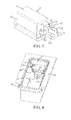
FIG. 1 is a schematic partial three-dimensional view of a cooling appliance according to a preferred embodiment of the present invention; -
FIG. 2 is a schematic exploded view of an upper hinge unit of the cooling appliance according to a preferred embodiment of the present invention; -
FIG. 3 is a three-dimensional view before a receiving member and an electrical connector are assembled according to a preferred embodiment of the present invention; and -
FIG. 4 is a three-dimensional view after the receiving member and the electrical connector are assembled according to a preferred embodiment of the present invention. - Firstly referring to
FIG. 1 andFIG. 2 , acooling appliance 1 includes acabinet 2 for defining at least one heat-insulated storage chamber (not shown) and adoor 13 connected to a front end of thecabinet 2 to close the corresponding storage chamber. Thecabinet 2 and thedoor 13 both have a heat-insulating layer (not shown), to reduce heat exchange of the interior of the storage chamber with the outside. The heat-insulating layer may be formed in a foaming process. Thecabinet 2 and thedoor 13 together form a heat-insulating housing of thecooling appliance 1. - The
door 13 is pivotally connected to thecabinet 2, and is rotatable about a longitudinal axis. An upper end of thedoor 13 is connected to thecabinet 2 through anupper hinge 14. - An end of the
upper hinge 14 is connected in thedoor 13. Specifically, a hingeaxial portion 27 of theupper hinge 14 is inserted into a hinge hole 26 on thedoor 13. The other end of theupper hinge 14 is plate-like, and is fixed on thecabinet 2. - The
cabinet 2 is disposed with a recessed space 6 depressed from the housing on the top wall thereof. The recessed space 6 has an opening (not shown) facing the top side of thecabinet 2. Theupper hinge 14 is fixed in the recessed space 6, and a front end thereof extends to thedoor 13. - The
cooling appliance 1 includes amain control unit 22 located in thecabinet 2 and a displaying and/oroperating unit 23 located in thedoor 13. Thecooling appliance 1 further includes a transfer line connected between themain control unit 22 and the displaying and/oroperating unit 23 to transfer power from themain control unit 22 to the displaying and/oroperating unit 23 and transmit signals there-between. - The transfer line includes a cabinet-side cable 15 extending from the
main control unit 22 into the recessed space 6 and a door-side cable 16 extending from the displaying and/oroperating unit 23 into the recessed space 6. Ends of the cabinet-side cable 15 and the door-side cable 16 are respectively connected to a cabinet-side connector 17 and a door-side connector (not shown). The cabinet-side connector 17 and the door-side connector are connected in the recessed space 6 so as to make the cabinet-side cable 15 electrically connected to the door-side cable 16. - The cabinet-
side connector 17 includes aconnector housing 170 and several conductor terminals (not shown) fixed in theconnector housing 170. Theconnector housing 170 hasseveral terminal holes 171 to respectively accommodate a corresponding conductor terminal. - The conductor terminals are connected to the cabinet-side cable 15. Similarly, the door-side connector also has a connector housing and several conductor terminals connected to the door-
side cable 16. Through connecting between the conductor terminals of the cabinet-side connector 17 and the door-side connector, the cabinet-side cable 15 is electrically connected to the door-side cable 16. - In this embodiment, two cabinet-
side connectors 17 are provided, and correspondingly, two door-side connectors are provided. The two cabinet-side connectors 17 are arranged up and down, but have different transverse width and longitudinal height. It should be understood that, the number and specific construction of the electrical connector should not be limited in the present invention. - Referring to
FIG. 2 , the recessed space 6 includes afront portion 61 and a rear portion that is deeper than thefront portion 61. Theupper hinge 14 is accommodated in and is immovably fixed in thefront portion 61. - The cabinet-
side connector 17 and the door-side electrical connector are at least partially accommodated in the rear portion of the recessed space 6. According to a preferred embodiment of the present invention, the rear portion of the recessed space 6 is formed by a receivingmember 3 fixed in thecabinet 2. - Referring to
FIG. 2 to FIG. 4 , the receivingmember 3 is substantially box-like with an opening facing upwards. The receivingmember 3 includes abase wall 31, a surroundingwall 32 connected to thebase wall 31 and extending upwards, and a receivingspace 33 enclosed by thebase wall 31 and the surroundingwall 32. The receivingspace 33 forms the rear portion of the recessed space 6. - The receiving
member 3 includes aflange 35 bent outwards from the surroundingwall 32 and agroove 36 located on an upper end of the surroundingwall 32 and surrounding the receivingspace 33. The receivingmember 3 is connected to a housing 4 of thecabinet 2 before the foaming process of thecabinet 2 is implemented. Specifically, when the receivingmember 3 is connected to the housing 4, theflange 35 is attached to an inner side of the housing 4, and the housing 4 has a connecting flange (not shown) inserted into thegroove 36. After the foaming process is finished, the receivingmember 3 is closely joined to the inner side of the housing 4 and the heat-insulating layer, and is embedded in thecabinet 2 in an undetachable manner. - The receiving
member 3 has a pair of insertion holes 34 for communicating the interior of the receivingspace 33 with the outside. The insertion holes 34 may be formed on the surroundingwall 32. It should be understood that, according to the design requirement, the insertion holes 34 may also be formed on thebase wall 31. - Each cabinet-
side connector 17 extends into the receivingspace 33 from the receivingmember 3 through thecorresponding insertion hole 34. Theinsertion hole 34 penetrates the surroundingwall 32. In this embodiment, a part of theinsertion hole 34 also protrudes outwards from an outer side of the surroundingwall 32, so that the length of theinsertion hole 34 in an insertion direction is larger than the thickness of the surroundingwall 32. - According to the present invention, the cabinet-
side connector 17 is fixed on the receivingmember 3. A fixing mode between the cabinet-side connector 17 and the receivingmember 3 according to a preferred embodiment of the present invention is illustrated in detail below. - The
connector housing 170 of each cabinet-side connector 17 includes a pair ofelastic pieces 172 connected to a corresponding side of a front end of the cabinet-side connector 17 (an end that contacts with the door-side connector) and extending backwards. Theelastic piece 172 extends outwards from front to back, and has aninclined surface 173 that slants outwardly. A free end of theelastic piece 172 is bent inwards. - Each
insertion hole 34 has a shape and a size substantially corresponding to an external contour of the cabinet-side connector 17. Specifically, the transverse dimension of theinsertion hole 34 is set to enable theconnector housing 170 to enter after theelastic pieces 172 are extruded inwards. After theelastic pieces 172 penetrate from theinsertion hole 34, the distance between the ends of the pair ofelastic pieces 172 that restore to their natural states is larger than the transverse dimension of theinsertion hole 34, so that the elastic pieces can be butted against the inner side of the surroundingwall 32, to prevent the cabinet-side connector 17 from moving out of theinsertion hole 34. The longitudinal dimension of theinsertion hole 34 is slightly larger than that of theconnector housing 170, so as to limit the movement of theconnector housing 170 in the longitudinal direction. - The receiving
member 3 includes a pair ofstoppers 18 located opposite to each other in the receivingspace 33. In an embodiment, thestopper 18 has a shape like a plate and is perpendicular to the insertion direction of the cabinet-side connector 17. - The distance between the
stopper 18 and an inner end of theinsertion hole 34 is smaller than the length of theconnector housing 170. When the cabinet-side connector 17 extends into the receivingspace 33, the front end of theconnector housing 170 is abut against thestopper 18, so that theconnector housing 170 is stopped from moving more further in the insertion direction. A part of theconnector housing 170 is exposed in the receivingspace 33, and the remaining part thereof is maintained in theinsertion hole 34. Preferably, the rear end of theconnector housing 170 does not exceed that of theinsertion hole 34. - The
stopper 18 presses against a side surface of the correspondingelastic piece 172, so that in the insertion direction of the cabinet-side connector 17, thestopper 18 is not overlapped with a mating surface 174 (in this embodiment, a front surface) of theconnector housing 170 that contacts with the door-side connector. - The
stopper 18 is pressed against theincline surface 173 of theelastic piece 172 that is inclined outwardly, which limits the movement of theconnector housing 170 in the transverse direction and the insertion direction. - In an embodiment, the receiving
member 3 stops the two cabinet-side connectors 17 from moving forwards or moving from left to right by using the pair ofstoppers 18. Since the two cabinet-side connectors 17 have different width, thestoppers 18 are correspondingly step-like in a gap between the two cabinet-side connectors 17. - The cooling
appliance 1 includes ahinge lid 8 for a user to close the recessed space 6. Thehinge lid 8 extends from thecabinet 2 to above thedoor 13, so as to shield theupper hinge 14 and the receivingmember 3. - According to the embodiment of the present invention, the cabinet-
side connector 17 is fixed in the receivingmember 3 through a fixing structure provided by the receivingmember 3, so that the cabinet-side connector 17 is prevented from moving outside the receivingspace 33 to cause damages during the foaming process of thecabinet 2. - In the above embodiment, the receiving
member 3 is disposed near theupper hinge 14 to accommodate the cabinet-side connector 17 and the door-side connector. It should be understood that, the present invention should not be limited thereto, and other embodiments are also available. For example, the present invention is also applicable to an electrical connector for connecting at least two cables both located on the cabinet or door and a receiving member for accommodating such electrical connectors.
Claims (12)
- A cooling appliance (1), comprising:a heat-insulating housing (2) having a heat-insulating layer;a receiving member (3) embedded in the heat-insulating layer, wherein the receiving member (3) has a receiving space (33) and an insertion hole (34); andan electrical connector (17), being inserted through the insertion hole (34) and extending into the receiving space (33),characterized in that, the electrical connector (17) is fixed in the receiving member (3).
- The cooling appliance according to claim 1, characterized in that, the electrical connector (17) is hold in the insertion hole (34).
- The cooling appliance according to claim 2, characterized in that, the insertion hole (34) has a shape and a size substantially corresponding to an external contour of the electrical connector (17).
- The cooling appliance according to claim 2, characterized in that, the depth of the insertion hole (34) is larger than the thickness of a wall (32) where the insertion hole (34) is located.
- The cooling appliance according to claim 1, characterized in that, the receiving member (3) comprises at least one stopper (18) located in the receiving space (33), and the stopper (18) is abut against a front end of the electrical connector (17) to stop the electrical connector (17) from moving more further in an insertion direction of the electrical connector.
- The cooling appliance according to claim 5, characterized in that, the electrical connector (17) comprises a mating surface (174) for contacting with a mating connector, and in the insertion direction, the stopper (18) and the mating surface (174) are not overlapped.
- The cooling appliance according to claim 5, characterized in that, the stopper (18) is butted against a side surface (173) of the electrical connector (17), and in a direction opposite to the insertion direction, the side surface (173) slants outwardly.
- The cooling appliance according to claim 5, 6 or 7, characterized in that, the electrical connector (17) comprises a pair of elastic pieces (172) which are connected to a corresponding side of the front end of the electrical connector (17), and the stopper (18) is pressed against a corresponding elastic pieces (172).
- The cooling appliance according to claim 5, characterized in that, the stopper (18) has a shape of plate, and is perpendicular to the insertion direction of the electrical connector (17).
- The cooling appliance according to claim 1, characterized in that, the electrical connector (17) comprises a pair of elastic pieces (172), a free end of each of the elastic pieces (172) is abut against a wall (32) of the receiving member (13) where the insertion hole (34) is disposed, so as to stop the electrical connector (17) from moving in a direction opposite to an insertion direction of the electrical connector.
- The cooling appliance according to any one of above claims, characterized in that, the housing (2, 13) comprises a cabinet (2) and a door (13) connected to the cabinet (2), the cabinet (2) has a cabinet-side cable (15) connected to the electrical connector (17), the door (13) has a door-side cable (16), and the cabinet-side cable (15) and the door-side cable (16) are connected in the receiving space (33) through the electrical connector (17) and a mating electrical connector.
- The cooling appliance according to claim 11, comprising: a hinge (14) connected to the cabinet (2) and the door (13) and a lid (8) for covering the hinge (14) and the receiving member (3).
Applications Claiming Priority (1)
| Application Number | Priority Date | Filing Date | Title |
|---|---|---|---|
| CN201110364592.1A CN103105031B (en) | 2011-11-11 | 2011-11-11 | Refrigerating appliance |
Publications (2)
| Publication Number | Publication Date |
|---|---|
| EP2592371A2 true EP2592371A2 (en) | 2013-05-15 |
| EP2592371A3 EP2592371A3 (en) | 2017-11-15 |
Family
ID=47221958
Family Applications (1)
| Application Number | Title | Priority Date | Filing Date |
|---|---|---|---|
| EP12191383.4A Withdrawn EP2592371A3 (en) | 2011-11-11 | 2012-11-06 | Cooling appliance |
Country Status (2)
| Country | Link |
|---|---|
| EP (1) | EP2592371A3 (en) |
| CN (1) | CN103105031B (en) |
Cited By (5)
| Publication number | Priority date | Publication date | Assignee | Title |
|---|---|---|---|---|
| DE102014004572A1 (en) * | 2014-02-14 | 2015-08-20 | Liebherr-Hausgeräte Lienz Gmbh | Fridge and / or freezer |
| US20160091243A1 (en) * | 2014-09-30 | 2016-03-31 | Miele & Cie. Kg | Domestic appliance comprising two or more appliance units |
| EP3507553A4 (en) * | 2017-01-03 | 2019-09-18 | Samsung Electronics Co., Ltd. | FRIDGE |
| US10544983B2 (en) | 2017-01-03 | 2020-01-28 | Samsung Electronics Co., Ltd. | Refrigerator |
| US11598574B2 (en) | 2021-03-19 | 2023-03-07 | Electrolux Home Products, Inc. | Appliance door including a wireless module |
Families Citing this family (4)
| Publication number | Priority date | Publication date | Assignee | Title |
|---|---|---|---|---|
| CN106403470B (en) * | 2015-07-30 | 2020-09-22 | 博西华电器(江苏)有限公司 | Refrigerator with door |
| CN110337574A (en) * | 2017-03-03 | 2019-10-15 | 夏普株式会社 | The manufacturing method of refrigerator and refrigerator doors |
| CN107101448B (en) * | 2017-05-27 | 2020-03-06 | 合肥华凌股份有限公司 | Box body structure and refrigerator |
| CN111193139A (en) * | 2020-02-18 | 2020-05-22 | 珠海格力电器股份有限公司 | Terminal connection structure and electrical apparatus |
Citations (1)
| Publication number | Priority date | Publication date | Assignee | Title |
|---|---|---|---|---|
| US8033623B2 (en) | 2007-05-23 | 2011-10-11 | Lg Electronics Inc. | Refrigerator |
Family Cites Families (9)
| Publication number | Priority date | Publication date | Assignee | Title |
|---|---|---|---|---|
| US4715512A (en) * | 1981-09-03 | 1987-12-29 | Whirlpool Corporation | Insulated cabinet manufacture |
| TR200202566A2 (en) * | 2002-11-22 | 2004-06-21 | Vestel Beyaz E�Ya Sanay� Ve T�Caret A.�. | Electronically controlled cooler with door opening direction changeable. |
| JP2004239583A (en) * | 2003-02-10 | 2004-08-26 | Fujitsu General Ltd | refrigerator |
| DE102004013431B4 (en) * | 2003-03-20 | 2018-06-21 | Lg Electronics Inc. | refrigerator door |
| CN1590893A (en) * | 2003-08-25 | 2005-03-09 | 乐金电子(天津)电器有限公司 | Refrigerator terminal external shell sealing device |
| DE102004012538A1 (en) * | 2004-03-15 | 2005-10-06 | BSH Bosch und Siemens Hausgeräte GmbH | The refrigerator |
| KR100764279B1 (en) * | 2006-07-06 | 2007-10-05 | 엘지전자 주식회사 | Sound system of the refrigerator |
| CN201081483Y (en) * | 2007-08-07 | 2008-07-02 | 海信科龙电器股份有限公司 | Refrigerator |
| ES2345235B1 (en) * | 2008-07-21 | 2011-08-17 | Bsh Electrodomesticos España, S.A | THERMAL INSULATING HOUSING WITH PASSAGE PASSAGE. |
-
2011
- 2011-11-11 CN CN201110364592.1A patent/CN103105031B/en active Active
-
2012
- 2012-11-06 EP EP12191383.4A patent/EP2592371A3/en not_active Withdrawn
Patent Citations (1)
| Publication number | Priority date | Publication date | Assignee | Title |
|---|---|---|---|---|
| US8033623B2 (en) | 2007-05-23 | 2011-10-11 | Lg Electronics Inc. | Refrigerator |
Cited By (8)
| Publication number | Priority date | Publication date | Assignee | Title |
|---|---|---|---|---|
| DE102014004572A1 (en) * | 2014-02-14 | 2015-08-20 | Liebherr-Hausgeräte Lienz Gmbh | Fridge and / or freezer |
| US20160091243A1 (en) * | 2014-09-30 | 2016-03-31 | Miele & Cie. Kg | Domestic appliance comprising two or more appliance units |
| EP3507553A4 (en) * | 2017-01-03 | 2019-09-18 | Samsung Electronics Co., Ltd. | FRIDGE |
| US10544983B2 (en) | 2017-01-03 | 2020-01-28 | Samsung Electronics Co., Ltd. | Refrigerator |
| US11009286B2 (en) | 2017-01-03 | 2021-05-18 | Samsung Electronics Co., Ltd. | Refrigerator |
| US11656022B2 (en) | 2017-01-03 | 2023-05-23 | Samsung Electronics Co., Ltd. | Refrigerator |
| US11598574B2 (en) | 2021-03-19 | 2023-03-07 | Electrolux Home Products, Inc. | Appliance door including a wireless module |
| US12007160B2 (en) | 2021-03-19 | 2024-06-11 | Electrolux Home Products, Inc. | Appliance door including a wireless module |
Also Published As
| Publication number | Publication date |
|---|---|
| CN103105031B (en) | 2017-08-11 |
| CN103105031A (en) | 2013-05-15 |
| EP2592371A3 (en) | 2017-11-15 |
Similar Documents
| Publication | Publication Date | Title |
|---|---|---|
| CN103105031B (en) | Refrigerating appliance | |
| US10205256B2 (en) | Plug and electrical connector component | |
| US11495905B2 (en) | Electrical plug connector | |
| JP5914547B2 (en) | connector | |
| US9705217B2 (en) | Electrical connector | |
| US7824219B2 (en) | Electrical connector having a connecting sheet for resisting electronic interference | |
| US9450342B2 (en) | Plug connector assembly having improved anti-EMI performance | |
| CN201130756Y (en) | electrical connector housing | |
| US9450319B2 (en) | Cable connector and connector device having the same | |
| US9252531B2 (en) | Electrical connector with magnetic element | |
| JP2010067459A (en) | Receptacle connector and method of manufacturing the same | |
| US9673580B2 (en) | Electrical connector with improved contacts | |
| US7648385B2 (en) | Electrical connector having a LED device thereon | |
| CN101325299B (en) | Electric connector | |
| JP2013247110A (en) | Electric connector | |
| US7086908B2 (en) | Jack | |
| US7485016B2 (en) | Female terminal with guiding piece | |
| KR20110051135A (en) | Shield case and connector with it | |
| US8834206B2 (en) | Electrical connector with grounging plate | |
| US20090028498A1 (en) | Optical fiber connector | |
| CN101207249B (en) | electrical connector | |
| CN201130757Y (en) | electrical connector | |
| JP3167543U (en) | Card connector | |
| US20180051926A1 (en) | Door for refrigerator and refrigerator | |
| JP2010092742A (en) | Receptacle connector |
Legal Events
| Date | Code | Title | Description |
|---|---|---|---|
| PUAI | Public reference made under article 153(3) epc to a published international application that has entered the european phase |
Free format text: ORIGINAL CODE: 0009012 |
|
| AK | Designated contracting states |
Kind code of ref document: A2 Designated state(s): AL AT BE BG CH CY CZ DE DK EE ES FI FR GB GR HR HU IE IS IT LI LT LU LV MC MK MT NL NO PL PT RO RS SE SI SK SM TR |
|
| AX | Request for extension of the european patent |
Extension state: BA ME |
|
| RAP1 | Party data changed (applicant data changed or rights of an application transferred) |
Owner name: BSH HAUSGERAETE GMBH |
|
| PUAL | Search report despatched |
Free format text: ORIGINAL CODE: 0009013 |
|
| AK | Designated contracting states |
Kind code of ref document: A3 Designated state(s): AL AT BE BG CH CY CZ DE DK EE ES FI FR GB GR HR HU IE IS IT LI LT LU LV MC MK MT NL NO PL PT RO RS SE SI SK SM TR |
|
| AX | Request for extension of the european patent |
Extension state: BA ME |
|
| RIC1 | Information provided on ipc code assigned before grant |
Ipc: F25D 23/02 20060101AFI20171011BHEP |
|
| 17P | Request for examination filed |
Effective date: 20180515 |
|
| RBV | Designated contracting states (corrected) |
Designated state(s): AL AT BE BG CH CY CZ DE DK EE ES FI FR GB GR HR HU IE IS IT LI LT LU LV MC MK MT NL NO PL PT RO RS SE SI SK SM TR |
|
| GRAP | Despatch of communication of intention to grant a patent |
Free format text: ORIGINAL CODE: EPIDOSNIGR1 |
|
| INTG | Intention to grant announced |
Effective date: 20180724 |
|
| STAA | Information on the status of an ep patent application or granted ep patent |
Free format text: STATUS: THE APPLICATION IS DEEMED TO BE WITHDRAWN |
|
| 18D | Application deemed to be withdrawn |
Effective date: 20181204 |