EP2592325A1 - Lubrication system and wind turbine incorporating same - Google Patents
Lubrication system and wind turbine incorporating same Download PDFInfo
- Publication number
- EP2592325A1 EP2592325A1 EP12191851.0A EP12191851A EP2592325A1 EP 2592325 A1 EP2592325 A1 EP 2592325A1 EP 12191851 A EP12191851 A EP 12191851A EP 2592325 A1 EP2592325 A1 EP 2592325A1
- Authority
- EP
- European Patent Office
- Prior art keywords
- lubrication
- receptacle
- expandable
- component
- wind turbine
- Prior art date
- Legal status (The legal status is an assumption and is not a legal conclusion. Google has not performed a legal analysis and makes no representation as to the accuracy of the status listed.)
- Withdrawn
Links
- 238000005461 lubrication Methods 0.000 title claims abstract description 134
- 229920000728 polyester Polymers 0.000 claims description 8
- 239000000314 lubricant Substances 0.000 description 27
- 239000004519 grease Substances 0.000 description 17
- 238000005096 rolling process Methods 0.000 description 7
- 238000004519 manufacturing process Methods 0.000 description 3
- 230000008901 benefit Effects 0.000 description 2
- 238000013461 design Methods 0.000 description 2
- 238000011161 development Methods 0.000 description 2
- 230000000694 effects Effects 0.000 description 2
- 238000007689 inspection Methods 0.000 description 2
- 238000004891 communication Methods 0.000 description 1
- 230000008878 coupling Effects 0.000 description 1
- 238000010168 coupling process Methods 0.000 description 1
- 238000005859 coupling reaction Methods 0.000 description 1
- -1 dirt Substances 0.000 description 1
- 238000009826 distribution Methods 0.000 description 1
- 239000000428 dust Substances 0.000 description 1
- 210000005069 ears Anatomy 0.000 description 1
- 239000013536 elastomeric material Substances 0.000 description 1
- 230000007613 environmental effect Effects 0.000 description 1
- 239000012530 fluid Substances 0.000 description 1
- 230000006870 function Effects 0.000 description 1
- 231100001261 hazardous Toxicity 0.000 description 1
- 230000008595 infiltration Effects 0.000 description 1
- 238000001764 infiltration Methods 0.000 description 1
- 238000012423 maintenance Methods 0.000 description 1
- 239000000463 material Substances 0.000 description 1
- 238000000034 method Methods 0.000 description 1
- 238000012544 monitoring process Methods 0.000 description 1
- 230000002093 peripheral effect Effects 0.000 description 1
- 239000012858 resilient material Substances 0.000 description 1
- XLYOFNOQVPJJNP-UHFFFAOYSA-N water Substances O XLYOFNOQVPJJNP-UHFFFAOYSA-N 0.000 description 1
Images



Classifications
-
- F—MECHANICAL ENGINEERING; LIGHTING; HEATING; WEAPONS; BLASTING
- F16—ENGINEERING ELEMENTS AND UNITS; GENERAL MEASURES FOR PRODUCING AND MAINTAINING EFFECTIVE FUNCTIONING OF MACHINES OR INSTALLATIONS; THERMAL INSULATION IN GENERAL
- F16C—SHAFTS; FLEXIBLE SHAFTS; ELEMENTS OR CRANKSHAFT MECHANISMS; ROTARY BODIES OTHER THAN GEARING ELEMENTS; BEARINGS
- F16C33/00—Parts of bearings; Special methods for making bearings or parts thereof
- F16C33/30—Parts of ball or roller bearings
- F16C33/66—Special parts or details in view of lubrication
- F16C33/6603—Special parts or details in view of lubrication with grease as lubricant
- F16C33/6622—Details of supply and/or removal of the grease, e.g. purging grease
-
- F—MECHANICAL ENGINEERING; LIGHTING; HEATING; WEAPONS; BLASTING
- F03—MACHINES OR ENGINES FOR LIQUIDS; WIND, SPRING, OR WEIGHT MOTORS; PRODUCING MECHANICAL POWER OR A REACTIVE PROPULSIVE THRUST, NOT OTHERWISE PROVIDED FOR
- F03D—WIND MOTORS
- F03D80/00—Details, components or accessories not provided for in groups F03D1/00 - F03D17/00
- F03D80/70—Bearing or lubricating arrangements
-
- F—MECHANICAL ENGINEERING; LIGHTING; HEATING; WEAPONS; BLASTING
- F16—ENGINEERING ELEMENTS AND UNITS; GENERAL MEASURES FOR PRODUCING AND MAINTAINING EFFECTIVE FUNCTIONING OF MACHINES OR INSTALLATIONS; THERMAL INSULATION IN GENERAL
- F16C—SHAFTS; FLEXIBLE SHAFTS; ELEMENTS OR CRANKSHAFT MECHANISMS; ROTARY BODIES OTHER THAN GEARING ELEMENTS; BEARINGS
- F16C19/00—Bearings with rolling contact, for exclusively rotary movement
- F16C19/02—Bearings with rolling contact, for exclusively rotary movement with bearing balls essentially of the same size in one or more circular rows
- F16C19/04—Bearings with rolling contact, for exclusively rotary movement with bearing balls essentially of the same size in one or more circular rows for radial load mainly
- F16C19/08—Bearings with rolling contact, for exclusively rotary movement with bearing balls essentially of the same size in one or more circular rows for radial load mainly with two or more rows of balls
-
- F—MECHANICAL ENGINEERING; LIGHTING; HEATING; WEAPONS; BLASTING
- F16—ENGINEERING ELEMENTS AND UNITS; GENERAL MEASURES FOR PRODUCING AND MAINTAINING EFFECTIVE FUNCTIONING OF MACHINES OR INSTALLATIONS; THERMAL INSULATION IN GENERAL
- F16N—LUBRICATING
- F16N31/00—Means for collecting, retaining, or draining-off lubricant in or on machines or apparatus
-
- F—MECHANICAL ENGINEERING; LIGHTING; HEATING; WEAPONS; BLASTING
- F16—ENGINEERING ELEMENTS AND UNITS; GENERAL MEASURES FOR PRODUCING AND MAINTAINING EFFECTIVE FUNCTIONING OF MACHINES OR INSTALLATIONS; THERMAL INSULATION IN GENERAL
- F16C—SHAFTS; FLEXIBLE SHAFTS; ELEMENTS OR CRANKSHAFT MECHANISMS; ROTARY BODIES OTHER THAN GEARING ELEMENTS; BEARINGS
- F16C2300/00—Application independent of particular apparatuses
- F16C2300/10—Application independent of particular apparatuses related to size
- F16C2300/14—Large applications, e.g. bearings having an inner diameter exceeding 500 mm
-
- F—MECHANICAL ENGINEERING; LIGHTING; HEATING; WEAPONS; BLASTING
- F16—ENGINEERING ELEMENTS AND UNITS; GENERAL MEASURES FOR PRODUCING AND MAINTAINING EFFECTIVE FUNCTIONING OF MACHINES OR INSTALLATIONS; THERMAL INSULATION IN GENERAL
- F16C—SHAFTS; FLEXIBLE SHAFTS; ELEMENTS OR CRANKSHAFT MECHANISMS; ROTARY BODIES OTHER THAN GEARING ELEMENTS; BEARINGS
- F16C2360/00—Engines or pumps
- F16C2360/31—Wind motors
-
- F—MECHANICAL ENGINEERING; LIGHTING; HEATING; WEAPONS; BLASTING
- F16—ENGINEERING ELEMENTS AND UNITS; GENERAL MEASURES FOR PRODUCING AND MAINTAINING EFFECTIVE FUNCTIONING OF MACHINES OR INSTALLATIONS; THERMAL INSULATION IN GENERAL
- F16N—LUBRICATING
- F16N2250/00—Measuring
- F16N2250/04—Pressure
-
- Y—GENERAL TAGGING OF NEW TECHNOLOGICAL DEVELOPMENTS; GENERAL TAGGING OF CROSS-SECTIONAL TECHNOLOGIES SPANNING OVER SEVERAL SECTIONS OF THE IPC; TECHNICAL SUBJECTS COVERED BY FORMER USPC CROSS-REFERENCE ART COLLECTIONS [XRACs] AND DIGESTS
- Y02—TECHNOLOGIES OR APPLICATIONS FOR MITIGATION OR ADAPTATION AGAINST CLIMATE CHANGE
- Y02E—REDUCTION OF GREENHOUSE GAS [GHG] EMISSIONS, RELATED TO ENERGY GENERATION, TRANSMISSION OR DISTRIBUTION
- Y02E10/00—Energy generation through renewable energy sources
- Y02E10/70—Wind energy
- Y02E10/72—Wind turbines with rotation axis in wind direction
Definitions
- the subject matter disclosed herein relates generally to a lubrication system. More specifically, the subject matter disclosed herein relates to a lubrication system for a wind turbine.
- Wind turbines need to be inspected and serviced on a regular basis to keep them operating reliably and effectively.
- damage invariably occurs to the wind turbine either from external effects (e.g., lightning, wind, rain, hail, etc.) or from general wear and tear leading to fatigue of various components.
- the bearings and drives of the wind turbine need inspection and service, and typically a technician must climb the tower and enter the nacelle. This is a time consuming and labor intensive activity. In addition, there are limits placed on the number of climbs any one technician can perform per day. This can be particularly problematic when a wind farm has a large number of wind turbines, and each wind turbine needs to be inspected and/or serviced. Further, wind turbines typically must be shut down when personnel are inside the wind turbine, and this reduces the production capability of the wind turbine currently undergoing an inspection. Some wind turbine sites may be difficult to reach, as they may be located off-shore or in isolated and difficult to reach locations.
- the bearings and drives may be lubricated with grease, and this grease must be injected into the target component at pre-determined intervals of time. As the grease is injected into the component, some of the grease may be forced out of the component. Grease may also be forced out during use and operation of the wind turbine. Typically, grease is forced out of seals and this excess grease may undesirably accumulate on exterior surfaces of the component, exterior portions of the wind turbine, or on interior portions of the wind turbine, such as floors or walkways. A potentially hazardous working environment could be created by grease that undesirably accumulates on floors, ladders or walkways. Grease that accumulates on exterior portions of the wind turbine can also deter from the aesthetic appearance of the wind turbine.
- a lubrication system having one or more input ports in a component and one or more output ports in the component.
- An expandable lubrication receptacle is connected to the one or more output ports, and the expandable lubrication receptacle is configured for receiving a lubrication medium from the component.
- a wind turbine having a tower, a nacelle supported by the tower, and a rotor including one or more rotor blades.
- a lubrication system includes one or more input ports in a component and one or more output ports in the component.
- An expandable lubrication receptacle is connected to the one or more output ports, and the lubrication receptacle is configured for receiving a lubrication medium from the component.
- a lubrication system having one or more input ports and one or more output ports in a component.
- An expandable lubrication receptacle is connected to the one or more output ports, and the expandable lubrication receptacle wraps around at least a portion of the component.
- the expandable lubrication receptacle is configured for receiving a lubrication medium from the component.
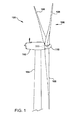
- a wind turbine 100 comprises a nacelle 102 housing a generator (not shown in FIG. 1 ). Nacelle 102 is supported by and mounted atop a tall tower 104, only a portion of which is shown in FIG. 1 .
- Wind turbine 100 also comprises a rotor 106 that includes one or more rotor blades 108 attached to a rotating hub 110.
- wind turbine 100 illustrated in FIG. 1 includes three rotor blades 108, there are no specific limits on the number of rotor blades 108 required by the present invention.
- various components are housed in nacelle 102 or in tower 104 of wind turbine 100.
- the height of tower 104 is selected based upon factors and conditions known in the art.
- one or more microcontrollers within control panel 112 comprise a control system used for overall system monitoring and control.
- Alternative distributed or centralized control architectures are used in some configurations.
- a variable blade pitch drive 114 may be provided to control the pitch of blades 108 (not shown in FIG. 2 ) that drive hub 110 as a result of wind.
- the pitch angles of blades 108 may be individually controlled by blade pitch drive 114.
- Hub 110 and blades 108 together comprise wind turbine rotor 106 (not shown in entirety in FIG. 2 ).
- the drive train of the wind turbine includes a main rotor shaft 116 (also referred to as a "low speed shaft”) connected to hub 110 via main bearing 130 and (in some configurations), at an opposite end of shaft 116 to a gear box 118.
- Gearbox 118 drives a high-speed shaft of generator 120.
- main rotor shaft 116 is coupled directly to generator 120.
- the high-speed shaft (not identified in FIG. 2 ) is used to drive generator 120, which is mounted on mainframe 132.
- rotor torque is transmitted via coupling 122.
- generator 120 is a direct drive permanent magnet generator.
- Yaw drive 124, yaw bearing 125 and yaw deck 126 provide a yaw orientation system for wind turbine 100.
- a meteorological boom 128 provides information for a turbine control system, which may include wind direction and/or wind speed.
- the yaw system is mounted on a flange provided atop tower 104.
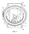
- FIG. 3 illustrates a perspective view of a pitch drive and pitch bearing 300 of the rotor hub with a removed blade for clarity.
- the pitch drive 114 which is firmly fixed to rotor hub 110, may be mounted inside the rotor hub.
- Drive element 305 of pitch drive 114 may be a gear wheel, which interacts with the inner gear rim of inner flange 310.
- Flange 310 may be firmly attached to a rotor blade and is rotatably located within rotor hub 110 (i.e., the rotor blade is attached to the rotating portion of the pitch bearing).
- pitch drive 114 enables a swiveling movement of its corresponding rotor blade, whereby the swivel axis of the rotor blade is roughly parallel to the longitudinal axis of the blade.
- Outer flange 320 may hold a stationary race for the rotor blade or pitch bearing and is bolted with a plurality of peripheral bolts 330 to the rotor hub 110.
- Lifting ears 160 with holes 165 may optionally be present and may be used for raising or lowering the hub.
- the pitch bearing is comprised of inner flange 310 and outer flange 320.
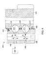
- FIG. 4 illustrates a partial, cross-sectional view of a pitch bearing 400 that may be used for a blade of a wind turbine, according to a view along section line 4-4 in FIG. 3 and to an aspect of the present invention.
- the pitch bearing 400, yaw bearing 125, main bearing 130, generator bearing (not shown) or any other bearing or item requiring lubrication may be considered a component or components of wind turbine 100.
- the outer flange 320 is fixed and bolted to the rotor hub 110.
- the inner flange 310 is connected to a rotor blade and is configured to rotate about a central axis (not shown).
- a plurality of rolling elements 410 are located between the inner flange 310 and the outer flange 320.
- the rolling elements may comprise ball bearings, spherical elements, cylindrical bearings, tapered roller bearings, or any other suitable friction reducing element.
- the rolling elements may be arranged in one, two or more rows as desired in the specific application.
- a cage 415 may be used in conjunction with the rolling elements, and the cage 415 helps to stabilize the tangential or circumferential position of the rolling elements.
- An inner seal 420 and an outer seal 422 may be formed of a resilient and/or elastomeric material and function to prevent or reduce infiltration of unwanted material (e.g., dirt, dust, water, etc.) or escape of desired lubrication fluids.
- a lubricant e.g., grease
- the lubricant reduces friction and wear, thereby increasing longevity of the bearing 400.
- the lubricant is injected into bearing 400 via one or more input ports 430 having a first diameter D I .
- the input port 430 may be a grease fitting configured for use with a grease gun or grease supply connection.
- Excess lubricant may be routed out of bearing 400 through one or more output ports 440 having a second diameter Do.
- the second diameter Do is larger than the first diameter D I .
- the first diameter D I may be in the range of about 8-14 mm and the second diameter Do may be in the range of about 14-20 mm, however, any suitable range of diameters may be used as desired in the specific application. It is desirable to reduce or eliminate lubricant leakage through seals 420, 422 as this leaked lubricant could damage the seals and/or accumulate on undesired surfaces. Therefore, the larger diameter output port 440 (compared to the diameter of input port 430) provides a lower flow resistance for the lubricant compared to either the input port 430 or the seals 420, 422.
- lubricant may be forced out of the bearing due to mechanical loads, temperature increases or other forces. Lubricant may also be forced out of bearing 400 by the addition of new lubricant forced through input ports 430.
- a lubricant or lubrication receptacle 450 can be connected to the one or more output ports to capture or receive the excess or expelled lubricant or lubrication medium.
- FIG. 5 illustrates a simplified perspective view of a lubrication system 500, according to an aspect of the present invention.
- Lubrication system 500 includes a component needing lubrication, such as a bearing comprised of inner flange 310 and outer flange 320.
- One or more input ports 430 may be located on or in outer flange 320.
- one or more input ports 530 may be located on or in inner flange 310.
- An expandable lubrication receptacle 550 is connected to a plurality of the one or more output ports 440.
- the expandable lubrication receptacle 550 may comprise any suitable device, and as one non-limiting example, the lubricant or lubrication receptacle may comprise a lay-flat or collapsible-type hose.
- the lubricant or lubrication receptacle may comprise a lay-flat or collapsible-type hose.
- one such expandable or collapsible hose is a discharge hose formed of an outer polyester cover jacket and an inner elastomeric or rubber liner. Diameters of the collapsible-type hose may range from about 1 inch to about 6 inches, but any suitable diameter may be used as desired in the specific application.
- a polyester/elastomeric hose may also withstand internal pressures of about 150 PSI and may maintain flexibility and integrity in a temperature range of about -25F to about 185F.
- lubrication receptacles with qualities outside the given ranges may also be employed as desired in the specific application.
- two lubrication receptacles 550 are shown connected to multiple output ports 440, however, it is to be understood that one, two, three or more lubrication receptacles could be employed as desired.
- the expandable lubrication receptacle 550 may be configured to wrap around at least a portion of the component. As non-limiting examples only, the expandable lubrication receptacle 550 could extend or wrap around about one fourth, about one third or about one half of the component (e.g., a bearing), or any other suitable amount as desired in the specific application.
- the expandable lubrication receptacle 550 can be initially installed in a collapsed state, and then as the lubricant medium (e.g., grease) fills the receptacle, the receptacle (or hose) would expand.
- lubricant medium e.g., grease
- the lubrication receptacle may also be purged or cleaned for re-use, and the lubricant previously contained therein may also be recycled and/or re-used.
- a lubricant supply or lubrication supply 560 may also be connected to the one or more input ports 430 and/or 530.
- the input ports 430/530 may be equally distributed about the component to permit substantially equal distribution of the lubricant medium.
- Any suitable supply conduit 564 may be used to transport the lubrication medium from the lubricant supply to the various input ports 430 and/or 530.
- the lubrication medium may be grease, synthetic grease, oil, synthetic oil, combinations thereof or any other desired lubricant as desired for the specific component.
- FIG. 6 illustrates a partial cut-away view of a portion of a lubrication system 600, according to an aspect of the present invention.
- a bearing includes rolling elements 410, inner flange 310 and outer flange 320.
- One or more input ports 630 and one or more output ports 640 are located in the outer flange 320.
- a lubrication receptacle 660 takes the form of a hose having an outer polyester cover jacket 662 and an inner elastomeric liner 664.
- the lubrication receptacle 660 may be attached to a connector 670, which may be a T-type connector or any other suitable connector.
- the connector 670 may be connected to an input connection 680, such as a quick connector or any other suitable connector.
- the lubrication receptacle 660 may also include one or more sensors 690 that can be used to determine amount of lubricant contained within the lubrication receptacle 660.
- the sensors 690 may detect internal pressure, external pressure, tension or any other parameter that indicates or can be used to determine the amount of lubricant within the receptacle or the level of "fullness" of the lubricant receptacle 660.
- the sensors 690 may be attached to the lubrication receptacle 660 (i.e., internally and/or externally), and/or embedded within the lubrication receptacle.
- the sensors may also transmit a signal 694 via antenna 692 to control panel 112 or any other suitable control device.
- the signal 694 can be used to determine if and/or when the lubrication receptacle 660 should be serviced, cleaned, emptied or replaced. As one non-limiting example only, if the sensor 690 detected a full state of the lubrication receptacle 660, then a signal could be sent to a lubrication system to cease further addition of lubricant until the lubrication receptacle was serviced.
- the sensor 690 may take the form of any suitable device as desired in the specific application (e.g., a RFID device, etc.) and may communicate with the control panel 112 or other control device via wired or wireless communication. One or more sensors 690 may be equally and/or unequally distributed along the length of the lubrication receptacle(s) 660.
- At least one sensor 690 may be used for detecting a parameter that indicates at least one of, the amount of lubricant within the lubricant receptacle 660, and/or the level of fullness of the lubricant receptacle 660.
- a signal 694 may be transmitted by the at least one sensor 690 to a control device 112 to indicate or notify if and/or when the lubrication receptacle 660 should be serviced.
Landscapes
- Engineering & Computer Science (AREA)
- General Engineering & Computer Science (AREA)
- Mechanical Engineering (AREA)
- Life Sciences & Earth Sciences (AREA)
- Sustainable Development (AREA)
- Sustainable Energy (AREA)
- Chemical & Material Sciences (AREA)
- Combustion & Propulsion (AREA)
- Wind Motors (AREA)
Abstract
Description
- The subject matter disclosed herein relates generally to a lubrication system. More specifically, the subject matter disclosed herein relates to a lubrication system for a wind turbine.
- Wind turbines need to be inspected and serviced on a regular basis to keep them operating reliably and effectively. However, damage invariably occurs to the wind turbine either from external effects (e.g., lightning, wind, rain, hail, etc.) or from general wear and tear leading to fatigue of various components.
- The bearings and drives of the wind turbine need inspection and service, and typically a technician must climb the tower and enter the nacelle. This is a time consuming and labor intensive activity. In addition, there are limits placed on the number of climbs any one technician can perform per day. This can be particularly problematic when a wind farm has a large number of wind turbines, and each wind turbine needs to be inspected and/or serviced. Further, wind turbines typically must be shut down when personnel are inside the wind turbine, and this reduces the production capability of the wind turbine currently undergoing an inspection. Some wind turbine sites may be difficult to reach, as they may be located off-shore or in isolated and difficult to reach locations.
- The bearings and drives may be lubricated with grease, and this grease must be injected into the target component at pre-determined intervals of time. As the grease is injected into the component, some of the grease may be forced out of the component. Grease may also be forced out during use and operation of the wind turbine. Typically, grease is forced out of seals and this excess grease may undesirably accumulate on exterior surfaces of the component, exterior portions of the wind turbine, or on interior portions of the wind turbine, such as floors or walkways. A potentially hazardous working environment could be created by grease that undesirably accumulates on floors, ladders or walkways. Grease that accumulates on exterior portions of the wind turbine can also deter from the aesthetic appearance of the wind turbine.
- In an aspect of the present invention, a lubrication system is provided having one or more input ports in a component and one or more output ports in the component. An expandable lubrication receptacle is connected to the one or more output ports, and the expandable lubrication receptacle is configured for receiving a lubrication medium from the component.
- In another aspect of the present invention, a wind turbine is provided having a tower, a nacelle supported by the tower, and a rotor including one or more rotor blades. A lubrication system includes one or more input ports in a component and one or more output ports in the component. An expandable lubrication receptacle is connected to the one or more output ports, and the lubrication receptacle is configured for receiving a lubrication medium from the component.
- In yet another aspect of the present invention, a lubrication system is provided having one or more input ports and one or more output ports in a component. An expandable lubrication receptacle is connected to the one or more output ports, and the expandable lubrication receptacle wraps around at least a portion of the component. The expandable lubrication receptacle is configured for receiving a lubrication medium from the component.
- Various aspects and embodiments of the present invention will now be described in connection with the accompanying drawings, in which:
-
FIG. 1 is a partial side elevational illustration of a wind turbine, according to an aspect of the present invention; -
FIG. 2 is a partial perspective illustration of the interior of the nacelle of the wind turbine ofFIG. 1 , according to an aspect of the present invention; -
FIG. 3 illustrates a perspective view of a pitch drive and pitch bearing; -
FIG. 4 illustrates a partial, cross-sectional view of a pitch bearing, according to an aspect of the present invention; -
FIG. 5 illustrates a simplified perspective view of a lubrication system, according to an aspect of the present invention; and -
FIG. 6 illustrates a partial cut-away view of a portion of a lubrication system, according to an aspect of the present invention. - One or more specific embodiments of the present invention will be described below. In an effort to provide a concise description of these embodiments, all features of an actual implementation may not be described in the specification. It should be appreciated that in the development of any such actual implementation, as in any engineering or design project, numerous implementation-specific decisions must be made to achieve the developers' specific goals, such as compliance with system-related and business-related constraints, which may vary from one implementation to another. Moreover, it should be appreciated that such a development effort might be complex and time consuming, but would nevertheless be a routine undertaking of design, fabrication, and manufacture for those of ordinary skill having the benefit of this disclosure.
- When introducing elements of various embodiments of the present invention, the articles "a," "an," "the," and "said" are intended to mean that there are one or more of the elements. The terms "comprising," "including," and "having" are intended to be inclusive and mean that there may be additional elements other than the listed elements. Any examples of operating parameters and/or environmental conditions are not exclusive of other parameters/conditions of the disclosed embodiments. Additionally, it should be understood that references to "one embodiment", "one aspect" or "an embodiment" or "an aspect" of the present invention are not intended to be interpreted as excluding the existence of additional embodiments that also incorporate the recited features.
- In some configurations and referring to
FIG. 1 , awind turbine 100 comprises anacelle 102 housing a generator (not shown inFIG. 1 ). Nacelle 102 is supported by and mounted atop atall tower 104, only a portion of which is shown inFIG. 1 .Wind turbine 100 also comprises arotor 106 that includes one ormore rotor blades 108 attached to arotating hub 110. Althoughwind turbine 100 illustrated inFIG. 1 includes threerotor blades 108, there are no specific limits on the number ofrotor blades 108 required by the present invention. - Referring to
FIG. 2 , various components are housed innacelle 102 or intower 104 ofwind turbine 100. The height oftower 104 is selected based upon factors and conditions known in the art. In some configurations, one or more microcontrollers withincontrol panel 112 comprise a control system used for overall system monitoring and control. Alternative distributed or centralized control architectures are used in some configurations. A variableblade pitch drive 114 may be provided to control the pitch of blades 108 (not shown inFIG. 2 ) that drivehub 110 as a result of wind. The pitch angles ofblades 108 may be individually controlled byblade pitch drive 114.Hub 110 andblades 108 together comprise wind turbine rotor 106 (not shown in entirety inFIG. 2 ). - The drive train of the wind turbine includes a main rotor shaft 116 (also referred to as a "low speed shaft") connected to
hub 110 via main bearing 130 and (in some configurations), at an opposite end ofshaft 116 to agear box 118. Gearbox 118 drives a high-speed shaft ofgenerator 120. In other configurations,main rotor shaft 116 is coupled directly togenerator 120. The high-speed shaft (not identified inFIG. 2 ) is used to drivegenerator 120, which is mounted onmainframe 132. In some configurations, rotor torque is transmitted viacoupling 122. In some configurations of the present invention,generator 120 is a direct drive permanent magnet generator. Yawdrive 124, yaw bearing 125 andyaw deck 126 provide a yaw orientation system forwind turbine 100. Ameteorological boom 128 provides information for a turbine control system, which may include wind direction and/or wind speed. In some configurations, the yaw system is mounted on a flange provided atoptower 104. -
FIG. 3 illustrates a perspective view of a pitch drive and pitch bearing 300 of the rotor hub with a removed blade for clarity. Thepitch drive 114, which is firmly fixed torotor hub 110, may be mounted inside the rotor hub.Drive element 305 ofpitch drive 114 may be a gear wheel, which interacts with the inner gear rim ofinner flange 310.Flange 310 may be firmly attached to a rotor blade and is rotatably located within rotor hub 110 (i.e., the rotor blade is attached to the rotating portion of the pitch bearing). Thus,pitch drive 114 enables a swiveling movement of its corresponding rotor blade, whereby the swivel axis of the rotor blade is roughly parallel to the longitudinal axis of the blade.Outer flange 320 may hold a stationary race for the rotor blade or pitch bearing and is bolted with a plurality ofperipheral bolts 330 to therotor hub 110. Liftingears 160 withholes 165 may optionally be present and may be used for raising or lowering the hub. The pitch bearing is comprised ofinner flange 310 andouter flange 320. -
FIG. 4 illustrates a partial, cross-sectional view of a pitch bearing 400 that may be used for a blade of a wind turbine, according to a view along section line 4-4 inFIG. 3 and to an aspect of the present invention. Thepitch bearing 400, yaw bearing 125,main bearing 130, generator bearing (not shown) or any other bearing or item requiring lubrication may be considered a component or components ofwind turbine 100. Theouter flange 320 is fixed and bolted to therotor hub 110. Theinner flange 310 is connected to a rotor blade and is configured to rotate about a central axis (not shown). A plurality of rollingelements 410 are located between theinner flange 310 and theouter flange 320. The rolling elements may comprise ball bearings, spherical elements, cylindrical bearings, tapered roller bearings, or any other suitable friction reducing element. The rolling elements may be arranged in one, two or more rows as desired in the specific application. In some applications, acage 415 may be used in conjunction with the rolling elements, and thecage 415 helps to stabilize the tangential or circumferential position of the rolling elements. - An
inner seal 420 and anouter seal 422 may be formed of a resilient and/or elastomeric material and function to prevent or reduce infiltration of unwanted material (e.g., dirt, dust, water, etc.) or escape of desired lubrication fluids. For example, a lubricant (e.g., grease) may be desired between theinner flange 310 andouter flange 320 as well as around the rollingelements 410. The lubricant reduces friction and wear, thereby increasing longevity of thebearing 400. The lubricant is injected into bearing 400 via one ormore input ports 430 having a first diameter DI. Theinput port 430 may be a grease fitting configured for use with a grease gun or grease supply connection. Excess lubricant may be routed out of bearing 400 through one ormore output ports 440 having a second diameter Do. The second diameter Do is larger than the first diameter DI. As non-limiting examples only, the first diameter DI may be in the range of about 8-14 mm and the second diameter Do may be in the range of about 14-20 mm, however, any suitable range of diameters may be used as desired in the specific application. It is desirable to reduce or eliminate lubricant leakage throughseals input port 430 or theseals - During operation of the
bearing 400, lubricant may be forced out of the bearing due to mechanical loads, temperature increases or other forces. Lubricant may also be forced out of bearing 400 by the addition of new lubricant forced throughinput ports 430. As embodied by an aspect of the present invention, a lubricant orlubrication receptacle 450 can be connected to the one or more output ports to capture or receive the excess or expelled lubricant or lubrication medium. -
FIG. 5 illustrates a simplified perspective view of alubrication system 500, according to an aspect of the present invention.Lubrication system 500 includes a component needing lubrication, such as a bearing comprised ofinner flange 310 andouter flange 320. One ormore input ports 430 may be located on or inouter flange 320. Alternatively, or in addition toinput ports 430, one ormore input ports 530 may be located on or ininner flange 310. Anexpandable lubrication receptacle 550 is connected to a plurality of the one ormore output ports 440. Theexpandable lubrication receptacle 550 may comprise any suitable device, and as one non-limiting example, the lubricant or lubrication receptacle may comprise a lay-flat or collapsible-type hose. For example, one such expandable or collapsible hose is a discharge hose formed of an outer polyester cover jacket and an inner elastomeric or rubber liner. Diameters of the collapsible-type hose may range from about 1 inch to about 6 inches, but any suitable diameter may be used as desired in the specific application. A polyester/elastomeric hose may also withstand internal pressures of about 150 PSI and may maintain flexibility and integrity in a temperature range of about -25F to about 185F. However, lubrication receptacles with qualities outside the given ranges may also be employed as desired in the specific application. In the example shown inFIG. 5 , twolubrication receptacles 550 are shown connected tomultiple output ports 440, however, it is to be understood that one, two, three or more lubrication receptacles could be employed as desired. Further, theexpandable lubrication receptacle 550 may be configured to wrap around at least a portion of the component. As non-limiting examples only, theexpandable lubrication receptacle 550 could extend or wrap around about one fourth, about one third or about one half of the component (e.g., a bearing), or any other suitable amount as desired in the specific application. Theexpandable lubrication receptacle 550 can be initially installed in a collapsed state, and then as the lubricant medium (e.g., grease) fills the receptacle, the receptacle (or hose) would expand. One advantage provided by the lubrication receptacle, according to an aspect of the present invention, is that that the lubrication receptacle is capable of capturing large volumes of lubricant (e.g., grease), thereby extending maintenance intervals. This would be highly desirable in remotely located wind turbines, or in wind farms having a large number of wind turbines. The lubrication receptacle may also be purged or cleaned for re-use, and the lubricant previously contained therein may also be recycled and/or re-used. - A lubricant supply or
lubrication supply 560, containing alubrication medium 562, may also be connected to the one ormore input ports 430 and/or 530. Theinput ports 430/530 may be equally distributed about the component to permit substantially equal distribution of the lubricant medium. Anysuitable supply conduit 564 may be used to transport the lubrication medium from the lubricant supply to thevarious input ports 430 and/or 530. The lubrication medium may be grease, synthetic grease, oil, synthetic oil, combinations thereof or any other desired lubricant as desired for the specific component. -
FIG. 6 illustrates a partial cut-away view of a portion of alubrication system 600, according to an aspect of the present invention. A bearing includes rollingelements 410,inner flange 310 andouter flange 320. One ormore input ports 630 and one ormore output ports 640 are located in theouter flange 320. Alubrication receptacle 660 takes the form of a hose having an outerpolyester cover jacket 662 and an innerelastomeric liner 664. Thelubrication receptacle 660 may be attached to aconnector 670, which may be a T-type connector or any other suitable connector. Theconnector 670 may be connected to aninput connection 680, such as a quick connector or any other suitable connector. - The
lubrication receptacle 660 may also include one ormore sensors 690 that can be used to determine amount of lubricant contained within thelubrication receptacle 660. Thesensors 690 may detect internal pressure, external pressure, tension or any other parameter that indicates or can be used to determine the amount of lubricant within the receptacle or the level of "fullness" of thelubricant receptacle 660. Thesensors 690 may be attached to the lubrication receptacle 660 (i.e., internally and/or externally), and/or embedded within the lubrication receptacle. The sensors may also transmit asignal 694 viaantenna 692 to controlpanel 112 or any other suitable control device. Thesignal 694 can be used to determine if and/or when thelubrication receptacle 660 should be serviced, cleaned, emptied or replaced. As one non-limiting example only, if thesensor 690 detected a full state of thelubrication receptacle 660, then a signal could be sent to a lubrication system to cease further addition of lubricant until the lubrication receptacle was serviced. Thesensor 690 may take the form of any suitable device as desired in the specific application (e.g., a RFID device, etc.) and may communicate with thecontrol panel 112 or other control device via wired or wireless communication. One ormore sensors 690 may be equally and/or unequally distributed along the length of the lubrication receptacle(s) 660. - As one non-limiting example only, at least one
sensor 690 may be used for detecting a parameter that indicates at least one of, the amount of lubricant within thelubricant receptacle 660, and/or the level of fullness of thelubricant receptacle 660. Asignal 694 may be transmitted by the at least onesensor 690 to acontrol device 112 to indicate or notify if and/or when thelubrication receptacle 660 should be serviced. - This written description uses examples to disclose the invention, including the preferred mode, and also to enable any person skilled in the art to practice the invention, including making and using any devices or systems and performing any incorporated methods. The patentable scope of the invention is defined by the claims, and may include other examples that occur to those skilled in the art. Such other examples are intended to be within the scope of the claims if they have structural elements that do not differ from the literal language of the claims, or if they include equivalent structural elements with insubstantial differences from the literal languages of the claims.
- Various aspects and embodiments of the present invention are defined by the following numbered clauses:
- 1. A lubrication system comprising:
- one or more input ports in a component;
- one or more output ports in the component;
- wherein an expandable lubrication receptacle is connected to the one or more output ports, and the lubrication receptacle is configured for receiving a lubrication medium from the component.
- 2. The lubrication system of clause 1, wherein a diameter of the one or more input ports is smaller than a diameter of the one or more output ports.
- 3. The lubrication system of any preceding clause, wherein the expandable lubrication receptacle comprises one or more hoses, and each of the one or more hoses is connected to a plurality of the one or more output ports.
- 4. The lubrication system of any preceding clause, wherein the one or more hoses comprise at least one collapsible-type hose.
- 5. The lubrication system of any preceding clause, wherein the collapsible-type hose comprises an outer polyester cover jacket and an inner elastomeric liner.
- 6. The lubrication system of any preceding clause, further comprising:
- a lubrication supply connected to the one or more input ports, the lubrication supply configured to supply the lubrication medium to the component.
- 7. The lubrication system of any preceding clause, wherein the component is at least one of:
- a bearing, a pitch bearing, a yaw bearing and a main bearing.
- 8. The lubrication system of any preceding clause, further comprising:
- at least one sensor for detecting a parameter that indicates at least one of, the amount of lubrication medium within the expandable lubrication receptacle, and the level of fullness of the expandable lubrication receptacle;
- wherein a signal may be transmitted by the at least one sensor to a control device to indicate if the expandable lubrication receptacle should be serviced.
- 9. A wind turbine comprising:
- a tower;
- a nacelle supported by the tower;
- a rotor including one or more rotor blades;
- a lubrication system comprising:
- one or more input ports in a component;
- one or more output ports in the component;
- wherein an expandable lubrication receptacle is connected to the one or more output ports, and the expandable lubrication receptacle is configured for receiving a lubrication medium from the component.
- 10. The wind turbine of any preceding clause, wherein a diameter of the one or more input ports is smaller than a diameter of the one or more output ports.
- 11. The wind turbine of any preceding clause, wherein the expandable lubrication receptacle comprises one or more collapsible-type hoses, and each of the one or more collapsible-type hoses is connected to a plurality of the one or more output ports.
- 12. The wind turbine of any preceding clause, wherein each of the one or more collapsible-type hoses comprise an outer polyester cover jacket and an inner elastomeric liner.
- 13. The wind turbine of any preceding clause, further comprising:
- a lubrication supply connected to the one or more input ports, the lubrication supply configured to supply the lubrication medium to the component.
- 14. The wind turbine of any preceding clause, wherein the component is at least one of:
- a bearing, a pitch bearing, a yaw bearing and a main bearing.
- 15. The wind turbine of any preceding clause, further comprising:
- at least one sensor for detecting a parameter that indicates at least one of, the amount of lubrication medium within the expandable lubrication receptacle, and the level of fullness of the expandable lubrication receptacle;
- wherein a signal is transmitted by the at least one sensor to a control device to indicate if the expandable lubrication receptacle should be serviced.
- 16. A lubrication system comprising:
- one or more input ports in a component;
- one or more output ports in the component;
- wherein an expandable lubrication receptacle is connected to the one or more output ports, the expandable lubrication receptacle wrapping around at least a portion of the component, and wherein the expandable lubrication receptacle is configured for receiving a lubrication medium from the component.
- 17. The lubrication system of any preceding clause, wherein the expandable lubrication receptacle comprises one or more collapsible-type hoses, and each of the one or more collapsible-type hoses is connected to a plurality of the one or more output ports.
- 18. The lubrication system of any preceding clause, wherein each of the one or more collapsible-type hoses comprise an outer polyester cover jacket and an inner elastomeric liner.
- 19. The lubrication system of any preceding clause, wherein a diameter of the one or more input ports is smaller than a diameter of the one or more output ports.
- 20. The lubrication system of any preceding clause, further comprising:
- at least one sensor for detecting a parameter that indicates at least one of, the amount of lubrication medium within the expandable lubrication receptacle, and the level of fullness of the expandable lubrication receptacle;
- wherein the component is at least one of a bearing, a pitch bearing, a yaw bearing and a main bearing; and
- wherein a signal may be transmitted by the at least one sensor to a control device to indicate if the expandable lubrication receptacle should be serviced.
Claims (15)
- A lubrication system (500) comprising:one or more input ports (430, 530) in a component (310, 320);one or more output ports (440) in the component;wherein an expandable lubrication receptacle (550) is connected to the one or more output ports, and the lubrication receptacle is configured for receiving a lubrication medium (562) from the component.
- The lubrication system (500) of claim 1, wherein a diameter of the one or more input ports (430) is smaller than a diameter of the one or more output ports (440).
- The lubrication system (500) of any preceding claim, wherein the expandable lubrication receptacle (550) comprises one or more hoses, and each of the one or more hoses is connected to a plurality of the one or more output ports (440).
- The lubrication system (500) of claim 3, wherein the one or more hoses comprise at least one collapsible-type hose.
- The lubrication system (500) of claim 4, wherein the collapsible-type hose comprises an outer polyester cover jacket (662) and an inner elastomeric liner (664).
- The lubrication system (500) of any preceding claim, further comprising:a lubrication supply (560) connected to the one or more input ports, the lubrication supply configured to supply the lubrication medium (562) to the component.
- The lubrication system (500) of any preceding claim, wherein the component is at least one of:a bearing, a pitch bearing, a yaw bearing and a main bearing.
- The lubrication system (500) of any preceding claim, further comprising:at least one sensor (690) for detecting a parameter that indicates at least one of, the amount of lubrication medium within the expandable lubrication receptacle, and the level of fullness of the expandable lubrication receptacle;wherein a signal (694) may be transmitted by the at least one sensor to a control device (112) to indicate if the expandable lubrication receptacle should be serviced.
- A wind turbine (100) comprising:a tower (104);a nacelle (102) supported by the tower;a rotor (106) including one or more rotor blades (108);a lubrication system (500) comprising:one or more input ports (430, 530) in a component (310, 320);one or more output ports (440) in the component;wherein an expandable lubrication receptacle (550) is connected to the one or more output ports, and the expandable lubrication receptacle is configured for receiving a lubrication medium (562) from the component.
- The wind turbine (100) of claim 9, wherein a diameter of the one or more input ports (430) is smaller than a diameter of the one or more output ports (440).
- The wind turbine (100) of claim 9 or claim 10, wherein the expandable lubrication receptacle (550) comprises one or more collapsible-type hoses, and each of the one or more collapsible-type hoses is connected to a plurality of the one or more output ports.
- The wind turbine (100) of claim 11, wherein each of the one or more collapsible-type hoses comprise an outer polyester cover jacket (662) and an inner elastomeric liner (664).
- The wind turbine (100) of any of claims 9 to 12, further comprising:a lubrication supply (560) connected to the one or more input ports, the lubrication supply configured to supply the lubrication medium (562) to the component.
- The wind turbine (100) of any of claims 9 to 13, wherein the component is at least one of:a bearing, a pitch bearing, a yaw bearing and a main bearing.
- The wind turbine (100) of any of claims 9 to 14, further comprising:at least one sensor (690) for detecting a parameter that indicates at least one of, the amount of lubrication medium within the expandable lubrication receptacle, and the level of fullness of the expandable lubrication receptacle;wherein a signal (694) is transmitted by the at least one sensor to a control device to indicate if the expandable lubrication receptacle should be serviced.
Applications Claiming Priority (1)
| Application Number | Priority Date | Filing Date | Title |
|---|---|---|---|
| US13/291,266 US8366390B2 (en) | 2011-11-08 | 2011-11-08 | Lubrication system and wind turbine incorporating same |
Publications (1)
| Publication Number | Publication Date |
|---|---|
| EP2592325A1 true EP2592325A1 (en) | 2013-05-15 |
Family
ID=46126796
Family Applications (1)
| Application Number | Title | Priority Date | Filing Date |
|---|---|---|---|
| EP12191851.0A Withdrawn EP2592325A1 (en) | 2011-11-08 | 2012-11-08 | Lubrication system and wind turbine incorporating same |
Country Status (3)
| Country | Link |
|---|---|
| US (1) | US8366390B2 (en) |
| EP (1) | EP2592325A1 (en) |
| CN (1) | CN103089552A (en) |
Cited By (1)
| Publication number | Priority date | Publication date | Assignee | Title |
|---|---|---|---|---|
| EP4212724A1 (en) * | 2022-01-14 | 2023-07-19 | General Electric Renovables España S.L. | Lubrication system for a pitch bearing of a wind turbine |
Families Citing this family (12)
| Publication number | Priority date | Publication date | Assignee | Title |
|---|---|---|---|---|
| US9850881B2 (en) * | 2011-02-21 | 2017-12-26 | Vestas Wind Systems A/S | Sealing system and method of maintaining a clean environment in a wind turbine by absorbing lubricant used in the pitch or yaw bearings |
| GB201307794D0 (en) * | 2013-04-30 | 2013-06-12 | Romax Technology Ltd | Turbine main bearing lubrication |
| DE102013217322B4 (en) * | 2013-08-30 | 2015-12-24 | Aktiebolaget Skf | Outer ring for a rolling bearing and roller bearing |
| US9188107B2 (en) * | 2013-08-30 | 2015-11-17 | General Electric Company | Wind turbine bearings |
| DK178936B1 (en) * | 2014-08-28 | 2017-06-12 | Harry Højvang Sørensen | SLURRY DISTRIBUTOR |
| ES2638650T3 (en) * | 2015-04-21 | 2017-10-23 | Siemens Aktiengesellschaft | Bearing with minimized lubricant leakage |
| DK3179123T3 (en) * | 2015-12-08 | 2019-05-20 | Siemens Gamesa Renewable Energy As | Filling level of lubricant in a bearing |
| US10502195B2 (en) * | 2017-04-27 | 2019-12-10 | General Electric Company | Clamping apparatus for securing a main bearing of a wind turbine during an installation and/or repair procedure |
| CN107701902A (en) * | 2017-09-29 | 2018-02-16 | 郑州奥特科技有限公司 | Bearing waste grease auto-collection system and bearing move fat system certainly |
| CN109869290B (en) * | 2017-12-01 | 2023-11-03 | 武彩霞 | Windmill with automatic lubrication rust-proof device |
| CN109989895B (en) * | 2017-12-29 | 2020-02-11 | 新疆金风科技股份有限公司 | Lubricating method and device for yaw system of wind generating set |
| EP4139581B1 (en) * | 2020-04-21 | 2024-10-09 | Vestas Wind Systems A/S | Bearing monitoring by pressure sensor |
Citations (9)
| Publication number | Priority date | Publication date | Assignee | Title |
|---|---|---|---|---|
| JPH0635796U (en) * | 1991-01-19 | 1994-05-13 | 油谷重工株式会社 | Bearing grease recovery device |
| US5454960A (en) * | 1993-11-10 | 1995-10-03 | Advanced Building Technologies, Inc. | Oil change and recycling system |
| US20030048963A1 (en) * | 2001-07-06 | 2003-03-13 | Eric Jacquemont | Device for improving the lubrication of bearings, particularly in wind turbines |
| ES2199677A1 (en) * | 2002-06-11 | 2004-02-16 | Camax S L | Portable unit with incorporated grease media and automated control for wind turbines. (Machine-translation by Google Translate, not legally binding) |
| EP1433930A1 (en) * | 2002-12-23 | 2004-06-30 | Renault s.a.s. | Lubrication arrangement for a turbocharger |
| US20080099280A1 (en) * | 2006-10-27 | 2008-05-01 | Nordex Energy Gmbh | Apparatus for the lubrication of a roller bearing in a wind energy plant |
| EP2088316A2 (en) * | 2008-02-08 | 2009-08-12 | General Electric Company | Wind turbine comprising a thermal management system |
| US20100179011A1 (en) * | 2007-06-22 | 2010-07-15 | Vestas Wind Systems A/S | Lubrication system for a gearbox and wind turbine |
| CA2739085A1 (en) * | 2010-05-06 | 2011-11-06 | Siemens Aktiengesellschaft | Bearing, in particular for a wind turbine |
Family Cites Families (11)
| Publication number | Priority date | Publication date | Assignee | Title |
|---|---|---|---|---|
| US4366746A (en) * | 1974-02-14 | 1983-01-04 | Aeroquip Corporation | Pressurized hydraulic fluid system using cross-linked chlorinated polyethylene hose |
| US4174031A (en) * | 1978-03-27 | 1979-11-13 | Rexnord Inc. | Lubricating system and method |
| US4697933A (en) * | 1986-03-31 | 1987-10-06 | Nippon Thompson Co., Ltd. | Fluid bearing assembly |
| DE3721264A1 (en) * | 1987-06-27 | 1989-01-12 | Schloemann Siemag Ag | SEALING DEVICE FOR ROLLER BEARINGS |
| US5628248A (en) * | 1996-01-11 | 1997-05-13 | The Minster Machine Co. | Fluid control system for rotating shaft or flywheel |
| US6023961A (en) * | 1998-04-02 | 2000-02-15 | Reliance Electric Industrial Company | Micro-viscosity sensor and lubrication analysis system employing the same |
| CN100558867C (en) * | 2004-02-09 | 2009-11-11 | Ntn株式会社 | Grease, rolling bearings, constant velocity couplings and rotating parts |
| US20050281499A1 (en) * | 2004-06-22 | 2005-12-22 | Wojtkowski Thomas Jr | Oil outlet for rolling mill oil film bearing |
| WO2008065088A2 (en) | 2006-11-28 | 2008-06-05 | Ecotecnia Energias Renovables, S.L. | A method for dynamically lubricating a wind turbine pitch blade bearing |
| CN101196175A (en) * | 2007-12-13 | 2008-06-11 | 苏州市南极风能源设备有限公司 | Wind power generation lubricating system |
| US8262347B2 (en) | 2008-01-17 | 2012-09-11 | Frontier Pro Services, Llc | Fluid catchment system for a wind turbine |
-
2011
- 2011-11-08 US US13/291,266 patent/US8366390B2/en not_active Expired - Fee Related
-
2012
- 2012-11-08 CN CN2012104425209A patent/CN103089552A/en active Pending
- 2012-11-08 EP EP12191851.0A patent/EP2592325A1/en not_active Withdrawn
Patent Citations (9)
| Publication number | Priority date | Publication date | Assignee | Title |
|---|---|---|---|---|
| JPH0635796U (en) * | 1991-01-19 | 1994-05-13 | 油谷重工株式会社 | Bearing grease recovery device |
| US5454960A (en) * | 1993-11-10 | 1995-10-03 | Advanced Building Technologies, Inc. | Oil change and recycling system |
| US20030048963A1 (en) * | 2001-07-06 | 2003-03-13 | Eric Jacquemont | Device for improving the lubrication of bearings, particularly in wind turbines |
| ES2199677A1 (en) * | 2002-06-11 | 2004-02-16 | Camax S L | Portable unit with incorporated grease media and automated control for wind turbines. (Machine-translation by Google Translate, not legally binding) |
| EP1433930A1 (en) * | 2002-12-23 | 2004-06-30 | Renault s.a.s. | Lubrication arrangement for a turbocharger |
| US20080099280A1 (en) * | 2006-10-27 | 2008-05-01 | Nordex Energy Gmbh | Apparatus for the lubrication of a roller bearing in a wind energy plant |
| US20100179011A1 (en) * | 2007-06-22 | 2010-07-15 | Vestas Wind Systems A/S | Lubrication system for a gearbox and wind turbine |
| EP2088316A2 (en) * | 2008-02-08 | 2009-08-12 | General Electric Company | Wind turbine comprising a thermal management system |
| CA2739085A1 (en) * | 2010-05-06 | 2011-11-06 | Siemens Aktiengesellschaft | Bearing, in particular for a wind turbine |
Cited By (2)
| Publication number | Priority date | Publication date | Assignee | Title |
|---|---|---|---|---|
| EP4212724A1 (en) * | 2022-01-14 | 2023-07-19 | General Electric Renovables España S.L. | Lubrication system for a pitch bearing of a wind turbine |
| US12258943B2 (en) | 2022-01-14 | 2025-03-25 | General Electric Renovables Espana, S.L. | Lubrication system for a pitch bearing of a wind turbine |
Also Published As
| Publication number | Publication date |
|---|---|
| CN103089552A (en) | 2013-05-08 |
| US8366390B2 (en) | 2013-02-05 |
| US20120134831A1 (en) | 2012-05-31 |
Similar Documents
| Publication | Publication Date | Title |
|---|---|---|
| US8366390B2 (en) | Lubrication system and wind turbine incorporating same | |
| US8212372B2 (en) | Wind turbine generator with seal mechanism | |
| EP3040553A1 (en) | Wind power generation station and gearbox | |
| US8622697B2 (en) | Ram air turbine bearing spacer | |
| US20110188988A1 (en) | Plain bearing for a wind turbine blade and method of operating a wind turbine having such a plain bearing | |
| CN102678890A (en) | Gear box structure and module, shaft, end cover, seal, lubricant and wind turbine | |
| US9528500B2 (en) | System for lubricating gears in a wind turbine | |
| CN101749196A (en) | Wind turbine and method of assembling the same | |
| EP2565477A1 (en) | Bearing system for a wind turbine comprising a rotatable scraper and a stationary scraper | |
| KR20130026501A (en) | Wind power generator | |
| EP2096303A1 (en) | Windturbine comprising a bearing seal | |
| CN105333017B (en) | Sealing device, wind-driven generator and Grease Collection method | |
| CN103899501A (en) | Gear box and module, shaft, wind turbine, and assembling method thereof | |
| CN112502919A (en) | Bearing arrangement for a wind turbine and wind turbine | |
| CA2974337C (en) | Bearing module for adjusting a rotor blade angle of attack in an underwater power plant | |
| CN106065901B (en) | Method outside wind turbine, its bearing and reduction leakage of lubricant to bearing | |
| EP2678559B1 (en) | Sealing system and method of maintaining a clean environment in a wind turbine by absorbing lubricant used in the pitch or yaw bearings. | |
| EP3974648B1 (en) | Grease collection arrangement for collecting waste grease from a grease lubricated rotor blade pitch bearing of a wind turbine | |
| US9976541B2 (en) | Turbine main bearing lubrication | |
| WO2016145564A1 (en) | Sealing system for a gearbox of a wind turbine | |
| CN120466148B (en) | Underground coal mine wind power generation device | |
| KR101021453B1 (en) | Wind power generator | |
| US9200619B2 (en) | Wind turbine yaw or pitch bearing utilizing a threaded bearing surface | |
| TWI637107B (en) | Wind power system | |
| CN106838260A (en) | A kind of detachable gear-box |
Legal Events
| Date | Code | Title | Description |
|---|---|---|---|
| PUAI | Public reference made under article 153(3) epc to a published international application that has entered the european phase |
Free format text: ORIGINAL CODE: 0009012 |
|
| AK | Designated contracting states |
Kind code of ref document: A1 Designated state(s): AL AT BE BG CH CY CZ DE DK EE ES FI FR GB GR HR HU IE IS IT LI LT LU LV MC MK MT NL NO PL PT RO RS SE SI SK SM TR |
|
| AX | Request for extension of the european patent |
Extension state: BA ME |
|
| 17P | Request for examination filed |
Effective date: 20131115 |
|
| RBV | Designated contracting states (corrected) |
Designated state(s): AL AT BE BG CH CY CZ DE DK EE ES FI FR GB GR HR HU IE IS IT LI LT LU LV MC MK MT NL NO PL PT RO RS SE SI SK SM TR |
|
| 17Q | First examination report despatched |
Effective date: 20140221 |
|
| GRAP | Despatch of communication of intention to grant a patent |
Free format text: ORIGINAL CODE: EPIDOSNIGR1 |
|
| INTG | Intention to grant announced |
Effective date: 20160210 |
|
| STAA | Information on the status of an ep patent application or granted ep patent |
Free format text: STATUS: THE APPLICATION IS DEEMED TO BE WITHDRAWN |
|
| 18D | Application deemed to be withdrawn |
Effective date: 20160621 |