EP2592316B1 - Clack valve assembly - Google Patents
Clack valve assembly Download PDFInfo
- Publication number
- EP2592316B1 EP2592316B1 EP12191642.3A EP12191642A EP2592316B1 EP 2592316 B1 EP2592316 B1 EP 2592316B1 EP 12191642 A EP12191642 A EP 12191642A EP 2592316 B1 EP2592316 B1 EP 2592316B1
- Authority
- EP
- European Patent Office
- Prior art keywords
- lid
- shaft
- valve assembly
- recess
- bearing
- Prior art date
- Legal status (The legal status is an assumption and is not a legal conclusion. Google has not performed a legal analysis and makes no representation as to the accuracy of the status listed.)
- Active
Links
Images


Classifications
-
- F—MECHANICAL ENGINEERING; LIGHTING; HEATING; WEAPONS; BLASTING
- F16—ENGINEERING ELEMENTS AND UNITS; GENERAL MEASURES FOR PRODUCING AND MAINTAINING EFFECTIVE FUNCTIONING OF MACHINES OR INSTALLATIONS; THERMAL INSULATION IN GENERAL
- F16K—VALVES; TAPS; COCKS; ACTUATING-FLOATS; DEVICES FOR VENTING OR AERATING
- F16K15/00—Check valves
- F16K15/02—Check valves with guided rigid valve members
- F16K15/03—Check valves with guided rigid valve members with a hinged closure member or with a pivoted closure member
-
- B—PERFORMING OPERATIONS; TRANSPORTING
- B64—AIRCRAFT; AVIATION; COSMONAUTICS
- B64D—EQUIPMENT FOR FITTING IN OR TO AIRCRAFT; FLIGHT SUITS; PARACHUTES; ARRANGEMENT OR MOUNTING OF POWER PLANTS OR PROPULSION TRANSMISSIONS IN AIRCRAFT
- B64D37/00—Arrangements in connection with fuel supply for power plant
- B64D37/005—Accessories not provided for in the groups B64D37/02 - B64D37/28
-
- F—MECHANICAL ENGINEERING; LIGHTING; HEATING; WEAPONS; BLASTING
- F16—ENGINEERING ELEMENTS AND UNITS; GENERAL MEASURES FOR PRODUCING AND MAINTAINING EFFECTIVE FUNCTIONING OF MACHINES OR INSTALLATIONS; THERMAL INSULATION IN GENERAL
- F16K—VALVES; TAPS; COCKS; ACTUATING-FLOATS; DEVICES FOR VENTING OR AERATING
- F16K17/00—Safety valves; Equalising valves, e.g. pressure relief valves
- F16K17/02—Safety valves; Equalising valves, e.g. pressure relief valves opening on surplus pressure on one side; closing on insufficient pressure on one side
- F16K17/12—Safety valves; Equalising valves, e.g. pressure relief valves opening on surplus pressure on one side; closing on insufficient pressure on one side weight-loaded
-
- Y—GENERAL TAGGING OF NEW TECHNOLOGICAL DEVELOPMENTS; GENERAL TAGGING OF CROSS-SECTIONAL TECHNOLOGIES SPANNING OVER SEVERAL SECTIONS OF THE IPC; TECHNICAL SUBJECTS COVERED BY FORMER USPC CROSS-REFERENCE ART COLLECTIONS [XRACs] AND DIGESTS
- Y02—TECHNOLOGIES OR APPLICATIONS FOR MITIGATION OR ADAPTATION AGAINST CLIMATE CHANGE
- Y02T—CLIMATE CHANGE MITIGATION TECHNOLOGIES RELATED TO TRANSPORTATION
- Y02T50/00—Aeronautics or air transport
- Y02T50/40—Weight reduction
-
- Y—GENERAL TAGGING OF NEW TECHNOLOGICAL DEVELOPMENTS; GENERAL TAGGING OF CROSS-SECTIONAL TECHNOLOGIES SPANNING OVER SEVERAL SECTIONS OF THE IPC; TECHNICAL SUBJECTS COVERED BY FORMER USPC CROSS-REFERENCE ART COLLECTIONS [XRACs] AND DIGESTS
- Y10—TECHNICAL SUBJECTS COVERED BY FORMER USPC
- Y10T—TECHNICAL SUBJECTS COVERED BY FORMER US CLASSIFICATION
- Y10T137/00—Fluid handling
- Y10T137/0318—Processes
- Y10T137/0402—Cleaning, repairing, or assembling
- Y10T137/0491—Valve or valve element assembling, disassembling, or replacing
- Y10T137/0497—Fluid actuated or retarded
-
- Y—GENERAL TAGGING OF NEW TECHNOLOGICAL DEVELOPMENTS; GENERAL TAGGING OF CROSS-SECTIONAL TECHNOLOGIES SPANNING OVER SEVERAL SECTIONS OF THE IPC; TECHNICAL SUBJECTS COVERED BY FORMER USPC CROSS-REFERENCE ART COLLECTIONS [XRACs] AND DIGESTS
- Y10—TECHNICAL SUBJECTS COVERED BY FORMER USPC
- Y10T—TECHNICAL SUBJECTS COVERED BY FORMER US CLASSIFICATION
- Y10T137/00—Fluid handling
- Y10T137/7722—Line condition change responsive valves
- Y10T137/7837—Direct response valves [i.e., check valve type]
- Y10T137/7898—Pivoted valves
- Y10T137/7903—Weight biased
Definitions
- the present invention relates to a clack valve assembly and a method of assembling a clack valve assembly.
- Clack valves also known as check valves or flapper valves
- a clack valve may, for example, be mounted to a rib or another wall separating two compartments of a fuel system in an aircraft wing to control the flow of fuel between the two compartments, and in particular to allow fuel to flow in one direction between the two compartments but not in the other direction.
- a clack value may be designed and installed in an aircraft fuel tank such that, under positive G flight conditions, fuel can flow from a fuel tank into a collector box through the clack valve assembly, but not flow back out through it. Such an arrangement helps to ensure adequate fuel flow to the collector box under all engine feeding conditions, including gravity feed and when the quantity of fuel in the tank is low.
- GB1397393 and US2918934 describe non-return valves installed in pipes, the valves having a metallic lid with protrusions which are rotatably received by a housing member.
- GB2338749 describes a non-return valve in a compressor having a reed steel lid with protrusions which are rotatably received by a clip.
- WO2007019560 describes a non-return valve in a pump having a lid with a metallic plate with protrusions which are rotatably received by a housing.
- WO2011012581 describes a non-return valve mechanism having a lid pivotally connected to a swinging arm, the swinging arm having protrusions which are rotatably received by projections extending from a housing.
- EP1479554 describes a check valve assembly suitable to be inserted into a fuel tank spud for accommodating insertion of a refuelling nozzle.
- a first aspect of the invention provides a clack valve assembly according to claim 1.
- a second aspect of the invention provides a method of assembling a clack valve assembly according to the first aspect, the method comprising: inserting the shaft into the recess through the mouth of the recess; and then closing the mouth of the recess in the bearing with the retaining member, thus retaining the shaft within the recess.
- the shaft and the lid plate are integrally formed elements of a single part, which minimises part count compared with an alternative arrangement in which the shaft and lid plate are formed as separate parts.
- the shaft and lid plate are integrally formed elements of a single part of non-conductive material, which minimises the risk of electrostatic discharge or electromagnetic hazard, and also minimises corrosion.
- the shaft and lid plate are integrally formed elements of a single part of polymeric material such as Nylon 66, which may be reinforced with non-conductive fibres such as glass fibres.
- the shaft retaining member may comprise a stop feature which engages the lid when the lid opens beyond a stop angle to hinder the lid from opening beyond the stop angle.
- the clack valve assembly may comprise a first stop feature which engages the lid when the lid opens to a first stop angle to hinder the lid from opening beyond the first stop angle; and the shaft retaining member may comprise a second stop feature which engages the lid if the first stop feature fails to prevent the lid from opening beyond the first stop angle and reaches a second stop angle at which the second stop feature engages the lid and hinders the lid from opening beyond the second stop angle.
- the valve seat and the first stop feature may be integrally formed parts of a valve body member.
- the valve seat and the bearing may be integrally formed parts of a valve body member.
- the shaft retaining member may be attached to the valve body member by removable fasteners.
- the valve body member may be attached to a wall by removable fasteners. Some or all of the fasteners used to attach the valve body member to the wall may also be used to attach the shaft retaining member to the valve body member to minimise the part count.
- the lid body may comprise a lid plate and a pair of lid arms extending from the lid plate, and the shaft may extend between the lid arms.
- the shaft, the lid plate and the lid arms are integrally formed elements of a single part.
- the bearing may comprise a first bearing member and a second bearing member, each bearing member comprising a recess with a base, a mouth, and a pair of side walls between the base and the opening.
- the shaft may be received in the recesses of the first and second bearing members, and the shaft retaining member may close the mouths of the recesses in the bearing members, thus retaining the shaft within the recesses, so that the shaft can rotate within the recesses to enable the lid to rotate from a closed position in which it engages the valve seat to an open position in which it lifts away from the valve seat enabling fluid to flow through the opening in the valve seat.
- the lid plate may directly engage the valve seat, or more preferably the lid comprises a resilient sealing member which is attached to the lid plate and engages the valve seat when the lid is in its closed position.
- the sealing member may comprise a plate which covers the opening along with the lid plate, or it may be an O-ring or similar which does not cover the opening but rather just provides an annular seal against the valve seat.
- the base of the recess is preferably curved, typically with a constant radius of curvature.
- the clack valve assembly may be installed on a wall separating two regions, and may be used to control the flow of fluid between the two regions.
- the wall may be a wall of a fuel system, or may be a wall separating any two bodies of fluid.
- the clack valve assembly may be installed in a fuel system, for example in a wall or a rib separating two adjacent fuel compartments or a wall of a collector box.
- the clack valve assembly may be used to control fluid flow between two compartments in an aircraft fuel system, for example flow between two adjacent fuel tank bays or flow into and out of a collector box for supplying fuel to an engine under negative g flight conditions, or may generally be mounted to any wall separating two bodies of fluid to control flow between the two bodies.
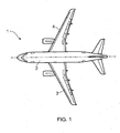
- Figure 1 illustrates a plan view of an aircraft 1 having a fuselage 2 and wings 3, 4.
- the aircraft 1 has a fuel tank located in the wing 3.
- the wing has front and rear spars 6, 7 which form front and rear walls of the fuel tank, as indicated in Figure 2 , while upper and lower covers of the wing form the top and bottom walls.
- the fuel tank is divided into a plurality of compartments 5a-5d by ribs 8a-8e which run between the front and rear spars 6, 7 and between the upper and lower covers.
- the rib 8c has several clack valve assemblies 9 installed along its length to control the flow of fuel between fuel tank compartments 5b and 5c.
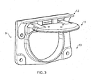
- Figure 3 illustrates the clack valve assembly 9.
- the assembly comprises three components: a valve base member 10 shown in Figure 4 , a lid assembly 11 shown in Figure 5 , and a retaining member 12 shown in Figure 6 .
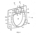
- the valve base member 10 comprises a base plate 40 with an opening 13 surrounded by a flange 14 with an annular end face 15.
- the opening 13 is aligned with a corresponding opening (not shown) in the rib 8c.
- the valve base member 10 has two bearing members 50 which project from the base plate 40.
- Each bearing member 50 has a recess with an open mouth 51, a semi cylindrical base 52, and a pair of parallel planar vertical side walls 53 between the base 52 and the mouth 51.
- the valve base member 10 is also provided with first and second stop features 18.
- valve base member 10 shown in Figure 4 All parts of the valve base member 10 shown in Figure 4 are integrally formed as a single part (for instance by injection moulding) from a polymer such as Nylon 66.
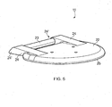
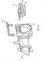
- the lid assembly 11 shown in Figure 5 comprises a lid plate 22, a shaft 23, a pair of arms 24, a nitrile rubber sealing member 25 and a seal holding plate 32 shown in Figures 9 and 10 .
- the lid plate 22, arms 24 and shaft 23 are integrally formed as a single part from a polymeric composite material such as Nylon 66 reinforced with glass fibres.
- the use of such non-conductive materials minimises the risk of electrostatic discharge or electromagnetic hazard, and also minimises corrosion.
- the sealing member 25 is held against the lid plate 22 by the holding plate 32, which is attached to the lid assembly by metal rivets 33 which pass through the lid plate 22, the sealing member 25 and the holding plate 32.
- the heads of the metal rivets are encapsulated by an over seal material 80 which reduces the isolated conductors exposed to surrounding structures.
- the shaft 23 has a circular cross section as shown in Figure 8 and is seated on the semi cylindrical bases 52 of the recesses 51 in the bearing members 50.
- the lid assembly 11 can, therefore, pivot relative to the valve base member 10 about the longitudinal axis of the shaft 23.
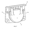
- the lid assembly 11 can pivot between a closed position shown in Figure 7 in which the sealing member 25 engages the end face 15 of the valve seat, thereby preventing fluid flow through the opening, and an open position shown in Figure 3 , in which the lid lifts away from the valve seat enabling fluid to flow through the opening.
- the sealing member 25 engages the end face 15 of the flange 14 so that the end face 15 acts as a valve seat.
- the lid plate 22 and the sealing member 25 both cover the opening 13. Both the lid plate 22 and the sealing member 25 have a greater area than the opening 13, when viewed perpendicular to the opening 13.
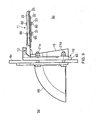
- the plane of the end face 15 lies at an acute angle to the vertical plane of the base plate 40 as shown in Figure 9 . This ensures that the lid assembly 11 remains closed when installed in a dihedral wing.
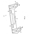
- the retaining member 12 shown in Figure 6 comprises a top plate 26; two location arms 27 with bolt holes 28a and 28b; two stop features 29; and a retaining element 31. All parts of the retaining member 12 shown in Figure 6 are integrally formed as a single part from a polymer such as Nylon 66 reinforced with glass fibres.
- the base plate 40 is attached to the rib 8c on the side of the rib 8c facing the compartment 5c by bolts (21a and 21d shown) passing through holes 20a-20d in the base plate 40.
- the bolts passing through the holes 20a,20b also pass through the holes 28a,28b in the location arms 27 of the retaining member 12, attaching the retaining member 12 to the base member 10.
- the lid assembly 11 is mounted on the base member 10 by positioning the shaft 23 within the recesses of the bearing members 50 so that the shaft 23 sits on the semi cylindrical bases 52, fitting the retaining plate member 12; and inserting the bolts.
- the top plate 26 of the retaining member closes the mouths 51 of the recesses, thus retaining the shaft 23 within the recesses.
- the retaining element 31 is also pushed into the recesses, with a small gap 70 between the retaining element 31 and the shaft 23.
- lid assembly 11 By attaching the lid assembly 11 to the valve base member 10 using a shaft, bearing member and retaining member as shown, separate metallic spindles and cotter pins are not required. The cost, complexity, part count and assembly time of the valve assembly 9 are therefore all minimised. Additionally, by forming the lid plate 22, shaft 23 and arms 24 of a non-metallic material, the number of isolated metallic parts in the fuel tank 5 is minimised.
- the movement of the lid assembly 11 relative to the valve base member 10 is controlled by the movement of the fuel through the valve assembly 9 and the pressure exerted on the faces of the lid plate 22 by fluids within the fuel tank 5.
- Fuel flow from compartment 5c towards compartment 5b will generally act to move the valve into its closed position while fuel flow through the opening 13 from compartment 5b into compartment 5c will generally act to keep the valve open.
- the lid rotates 83° about the axis of the shaft when moving between its closed position and its position of maximum opening.
- Figure 8 shows the lid in its closed position and its fully open position.
- Each arm has a protrusion 24' which extends beyond the shaft 23.
- the lid assembly 11 is prevented from rotating beyond a primary stop angle of about 83° by engagement of the protrusions 24' with the stop features 18 as shown in Figure 8 , which thus act as a primary stop mechanism.
- the valve assembly also has a redundant stop mechanism in the form of the stop features 29 on the retaining member 12. If the primary stop mechanism fails and permits the lid assembly to rotate beyond the primary stop angle shown in Figure 8 , then the stop features 29 engage with the arms 24 to prevent continued rotation beyond a secondary stop angle of about 90°.
- a metallic hood 60 shown in Figures 9 and 10 is attached to the rib 8c on the opposite side to the valve base 10 by the bolts 21a,21d etc.
- the hood 60 acts to channel fuel from compartment 5b through the valve assembly under negative g conditions.
- the hood 60 is bonded back to the rib 8c and the bolts 21a, 21d are bonded back to the hood 60 to minimise the risk of electrostatic discharge.
Landscapes
- Engineering & Computer Science (AREA)
- General Engineering & Computer Science (AREA)
- Mechanical Engineering (AREA)
- Aviation & Aerospace Engineering (AREA)
- Lift Valve (AREA)
- Check Valves (AREA)
- Cooling, Air Intake And Gas Exhaust, And Fuel Tank Arrangements In Propulsion Units (AREA)
Description
- The present invention relates to a clack valve assembly and a method of assembling a clack valve assembly.
- Clack valves (also known as check valves or flapper valves) are commonly used in aircraft fuel systems to control the flow of fuel between different compartments within the fuel system. A clack valve may, for example, be mounted to a rib or another wall separating two compartments of a fuel system in an aircraft wing to control the flow of fuel between the two compartments, and in particular to allow fuel to flow in one direction between the two compartments but not in the other direction.
- A clack value may be designed and installed in an aircraft fuel tank such that, under positive G flight conditions, fuel can flow from a fuel tank into a collector box through the clack valve assembly, but not flow back out through it. Such an arrangement helps to ensure adequate fuel flow to the collector box under all engine feeding conditions, including gravity feed and when the quantity of fuel in the tank is low.
- It is desirable to minimise the part count of clack valves in order to reduce cost, complexity, weight and assembly time and provide a rugged mechanism.
-
GB1397393 US2918934 describe non-return valves installed in pipes, the valves having a metallic lid with protrusions which are rotatably received by a housing member.GB2338749 WO2007019560 describes a non-return valve in a pump having a lid with a metallic plate with protrusions which are rotatably received by a housing.WO2011012581 describes a non-return valve mechanism having a lid pivotally connected to a swinging arm, the swinging arm having protrusions which are rotatably received by projections extending from a housing.EP1479554 describes a check valve assembly suitable to be inserted into a fuel tank spud for accommodating insertion of a refuelling nozzle. - A first aspect of the invention provides a clack valve assembly according to claim 1.
- A second aspect of the invention provides a method of assembling a clack valve assembly according to the first aspect, the method comprising: inserting the shaft into the recess through the mouth of the recess; and then closing the mouth of the recess in the bearing with the retaining member, thus retaining the shaft within the recess.
- The shaft and the lid plate are integrally formed elements of a single part, which minimises part count compared with an alternative arrangement in which the shaft and lid plate are formed as separate parts.
- The shaft and lid plate are integrally formed elements of a single part of non-conductive material, which minimises the risk of electrostatic discharge or electromagnetic hazard, and also minimises corrosion. Typically the shaft and lid plate are integrally formed elements of a single part of polymeric material such as
Nylon 66, which may be reinforced with non-conductive fibres such as glass fibres. The shaft retaining member may comprise a stop feature which engages the lid when the lid opens beyond a stop angle to hinder the lid from opening beyond the stop angle. - The clack valve assembly may comprise a first stop feature which engages the lid when the lid opens to a first stop angle to hinder the lid from opening beyond the first stop angle; and the shaft retaining member may comprise a second stop feature which engages the lid if the first stop feature fails to prevent the lid from opening beyond the first stop angle and reaches a second stop angle at which the second stop feature engages the lid and hinders the lid from opening beyond the second stop angle. The valve seat and the first stop feature may be integrally formed parts of a valve body member.
- The valve seat and the bearing may be integrally formed parts of a valve body member. The shaft retaining member may be attached to the valve body member by removable fasteners. The valve body member may be attached to a wall by removable fasteners. Some or all of the fasteners used to attach the valve body member to the wall may also be used to attach the shaft retaining member to the valve body member to minimise the part count.
- The lid body may comprise a lid plate and a pair of lid arms extending from the lid plate, and the shaft may extend between the lid arms. The shaft, the lid plate and the lid arms are integrally formed elements of a single part.
- The bearing may comprise a first bearing member and a second bearing member, each bearing member comprising a recess with a base, a mouth, and a pair of side walls between the base and the opening. The shaft may be received in the recesses of the first and second bearing members, and the shaft retaining member may close the mouths of the recesses in the bearing members, thus retaining the shaft within the recesses, so that the shaft can rotate within the recesses to enable the lid to rotate from a closed position in which it engages the valve seat to an open position in which it lifts away from the valve seat enabling fluid to flow through the opening in the valve seat.
- The lid plate may directly engage the valve seat, or more preferably the lid comprises a resilient sealing member which is attached to the lid plate and engages the valve seat when the lid is in its closed position. The sealing member may comprise a plate which covers the opening along with the lid plate, or it may be an O-ring or similar which does not cover the opening but rather just provides an annular seal against the valve seat.
- The base of the recess is preferably curved, typically with a constant radius of curvature.
- The clack valve assembly may be installed on a wall separating two regions, and may be used to control the flow of fluid between the two regions. The wall may be a wall of a fuel system, or may be a wall separating any two bodies of fluid.
- The clack valve assembly may be installed in a fuel system, for example in a wall or a rib separating two adjacent fuel compartments or a wall of a collector box.
- The clack valve assembly may be used to control fluid flow between two compartments in an aircraft fuel system, for example flow between two adjacent fuel tank bays or flow into and out of a collector box for supplying fuel to an engine under negative g flight conditions, or may generally be mounted to any wall separating two bodies of fluid to control flow between the two bodies.
- Embodiments of the invention will now be described with reference to the accompanying drawings, in which:
-
Figure 1 illustrates an aircraft; -
Figure 2 illustrates the layout of an aircraft fuel tank; -
Figure 3 illustrates an open clack valve assembly in accordance with an embodiment of the invention; -
Figure 4 illustrates a valve base; -
Figure 5 illustrates a valve lid; -
Figure 6 illustrates a shaft retaining member; and -
Figure 7 illustrates a closed clack valve assembly; -
Figure 8 is a side view, with hidden parts shown, showing the lid in its closed and fully open positions; -
Figure 9 is a side view of the assembly installed on a rib wall; and -
Figure 10 illustrates a kit of parts for assembling the clack valve assembly. -
Figure 1 illustrates a plan view of an aircraft 1 having afuselage 2 andwings wing 3. The wing has front andrear spars Figure 2 , while upper and lower covers of the wing form the top and bottom walls. - The fuel tank is divided into a plurality of
compartments 5a-5d byribs 8a-8e which run between the front andrear spars rib 8c has severalclack valve assemblies 9 installed along its length to control the flow of fuel betweenfuel tank compartments Figure 3 illustrates theclack valve assembly 9. The assembly comprises three components: avalve base member 10 shown inFigure 4 , alid assembly 11 shown inFigure 5 , and aretaining member 12 shown inFigure 6 . - Referring to
Figure 4 ; thevalve base member 10 comprises abase plate 40 with anopening 13 surrounded by aflange 14 with anannular end face 15. Theopening 13 is aligned with a corresponding opening (not shown) in therib 8c. Above the opening 13, thevalve base member 10 has two bearingmembers 50 which project from thebase plate 40. Each bearingmember 50 has a recess with anopen mouth 51, a semicylindrical base 52, and a pair of parallel planarvertical side walls 53 between thebase 52 and themouth 51. Thevalve base member 10 is also provided with first and second stop features 18. - All parts of the
valve base member 10 shown inFigure 4 are integrally formed as a single part (for instance by injection moulding) from a polymer such asNylon 66. - The
lid assembly 11 shown inFigure 5 comprises alid plate 22, ashaft 23, a pair ofarms 24, a nitrilerubber sealing member 25 and aseal holding plate 32 shown inFigures 9 and10 . Thelid plate 22,arms 24 andshaft 23 are integrally formed as a single part from a polymeric composite material such asNylon 66 reinforced with glass fibres. The use of such non-conductive materials minimises the risk of electrostatic discharge or electromagnetic hazard, and also minimises corrosion. Referring toFigure 9 : the sealingmember 25 is held against thelid plate 22 by the holdingplate 32, which is attached to the lid assembly bymetal rivets 33 which pass through thelid plate 22, the sealingmember 25 and the holdingplate 32. The heads of the metal rivets are encapsulated by an overseal material 80 which reduces the isolated conductors exposed to surrounding structures. - The
shaft 23 has a circular cross section as shown inFigure 8 and is seated on the semicylindrical bases 52 of therecesses 51 in the bearingmembers 50. Thelid assembly 11 can, therefore, pivot relative to thevalve base member 10 about the longitudinal axis of theshaft 23. - The
lid assembly 11 can pivot between a closed position shown inFigure 7 in which the sealingmember 25 engages theend face 15 of the valve seat, thereby preventing fluid flow through the opening, and an open position shown inFigure 3 , in which the lid lifts away from the valve seat enabling fluid to flow through the opening. In the closed position the sealingmember 25 engages theend face 15 of theflange 14 so that the end face 15 acts as a valve seat. When the lid assembly is in its closed position, thelid plate 22 and the sealingmember 25 both cover theopening 13. Both thelid plate 22 and the sealingmember 25 have a greater area than theopening 13, when viewed perpendicular to theopening 13. - The plane of the
end face 15 lies at an acute angle to the vertical plane of thebase plate 40 as shown inFigure 9 . This ensures that thelid assembly 11 remains closed when installed in a dihedral wing. - The retaining
member 12 shown inFigure 6 comprises atop plate 26; twolocation arms 27 withbolt holes element 31. All parts of the retainingmember 12 shown inFigure 6 are integrally formed as a single part from a polymer such asNylon 66 reinforced with glass fibres. - Referring to
Figure 9 : thebase plate 40 is attached to therib 8c on the side of therib 8c facing thecompartment 5c by bolts (21a and 21d shown) passing throughholes 20a-20d in thebase plate 40. The bolts passing through theholes holes location arms 27 of the retainingmember 12, attaching the retainingmember 12 to thebase member 10. Thelid assembly 11 is mounted on thebase member 10 by positioning theshaft 23 within the recesses of the bearingmembers 50 so that theshaft 23 sits on the semicylindrical bases 52, fitting the retainingplate member 12; and inserting the bolts. - As shown most clearly in
Figure 8 , thetop plate 26 of the retaining member closes themouths 51 of the recesses, thus retaining theshaft 23 within the recesses. The retainingelement 31 is also pushed into the recesses, with asmall gap 70 between the retainingelement 31 and theshaft 23. - By attaching the
lid assembly 11 to thevalve base member 10 using a shaft, bearing member and retaining member as shown, separate metallic spindles and cotter pins are not required. The cost, complexity, part count and assembly time of thevalve assembly 9 are therefore all minimised. Additionally, by forming thelid plate 22,shaft 23 andarms 24 of a non-metallic material, the number of isolated metallic parts in the fuel tank 5 is minimised. - The movement of the
lid assembly 11 relative to thevalve base member 10 is controlled by the movement of the fuel through thevalve assembly 9 and the pressure exerted on the faces of thelid plate 22 by fluids within the fuel tank 5. Fuel flow fromcompartment 5c towardscompartment 5b will generally act to move the valve into its closed position while fuel flow through the opening 13 fromcompartment 5b intocompartment 5c will generally act to keep the valve open. - The lid rotates 83° about the axis of the shaft when moving between its closed position and its position of maximum opening.
Figure 8 shows the lid in its closed position and its fully open position. Each arm has a protrusion 24' which extends beyond theshaft 23. The lid assembly 11is prevented from rotating beyond a primary stop angle of about 83° by engagement of the protrusions 24' with the stop features 18 as shown inFigure 8 , which thus act as a primary stop mechanism. - The valve assembly also has a redundant stop mechanism in the form of the stop features 29 on the retaining
member 12. If the primary stop mechanism fails and permits the lid assembly to rotate beyond the primary stop angle shown inFigure 8 , then the stop features 29 engage with thearms 24 to prevent continued rotation beyond a secondary stop angle of about 90°. - A metallic hood 60 shown in
Figures 9 and10 is attached to therib 8c on the opposite side to thevalve base 10 by thebolts compartment 5b through the valve assembly under negative g conditions. The hood 60 is bonded back to therib 8c and thebolts - Although the invention has been described above with reference to one or more preferred embodiments, it will be appreciated that various changes or modifications may be made without departing from the scope of the invention as defined in the appended claims.
Claims (14)
- A clack valve assembly (9) for installation on a wall separating adjacent compartments in an aircraft fuel system to control fluid communication between the adjacent compartments, the assembly comprising:a. a valve seat (15) comprising an opening (13); andb. a lid (11) comprising a lid plate (22) and a shaft (23), wherein the shaft and the lid plate are integrally formed elements of a single part;c. a bearing (50) comprising a recess with a base, a mouth, and a pair of side walls between the base and the mouth; andd. a shaft retaining member (12) which closes the mouth of the recess in the bearing, thus retaining the shaft within the recess,wherein the shaft is received in the recess of the bearing and can rotate within the recess to enable the lid to rotate from a closed position in which the lid engages the valve seat and covers the opening, to an open position in which the lid lifts away from the valve seat enabling fluid to flow through the opening in the valve seat, and wherein the lid is arranged to rotate from the closed position to the open position in response to pressure exerted on the lid plate by fluid flow between the adjacent compartments in a first direction, and from the open position to the closed position in response to pressure exerted on the lid plate by fluid flow between the adjacent compartments in a second direction opposite to the first direction, characterized in that the lid (11) is formed of a single part of non-conductive material.
- A clack valve assembly (9) according to claim 1 wherein the shaft retaining member (12) comprises a stop feature (29) which engages the lid (11) when the lid opens beyond a stop angle to hinder the lid from opening beyond the stop angle.
- A clack valve assembly (9) according to claim 1 further comprising a first stop feature (18) which engages the lid (11) when the lid opens to a first stop angle to hinder the lid from opening beyond the first stop angle; and wherein the shaft retaining member (12) comprises a second stop feature (29) which engages the lid if the first stop feature fails to prevent the lid from opening beyond the first stop angle and reaches a second stop angle at which the second stop feature engages the lid and hinders the lid from opening beyond the second stop angle.
- A clack valve assembly (9) according to claim 3 wherein the valve seat (15) and the first stop feature (18) are integrally formed elements of a valve body member (10).
- A clack valve assembly (9) according to any preceding claim wherein the valve seat (15) and the bearing (50) are integrally formed elements of a valve body member (10).
- A clack valve assembly (9) according to claim 5 wherein the shaft retaining member (12) is attached to the valve body member (10) by removable fasteners.
- A clack valve assembly (9) according to any preceding claim wherein the shaft (23) and lid plate (22) are integrally formed elements of a single part of polymeric material.
- A clack valve assembly (9) according to any preceding claim wherein the bearing comprises a first bearing member (50) and a second bearing member (50), each bearing member comprising a recess with a base, a mouth, and a pair of side walls between the base and the opening; the lid (11) comprises a lid plate (22) and a pair of lid arms (24) extending from the lid plate; the shaft (23) extends between the lid arms; the shaft, the lid plate and the lid arms are integrally formed elements of a single part; the shaft is received in the recesses of the first and second bearing members; and the shaft retaining member (12) closes the mouths of the recesses in the bearing members, thus retaining the shaft within the recesses, wherein the shaft can rotate within the recesses to enable the lid to rotate from a closed position in which it engages the valve seat (15) to an open position in which it lifts away from the valve seat enabling fluid to flow through the opening in the valve seat.
- A clack valve assembly (9) according to any preceding claim wherein the lid (11) comprises a resilient sealing member (25) which is attached to the lid plate (22) and which engages the valve seat (15) when the lid is in its closed position.
- A clack valve assembly (9) according to any preceding claim wherein the base of the recess (52) is curved.
- A clack valve assembly (9) according to any preceding claim wherein the lid plate (22) covers the opening (13) when the lid (11) is in its closed position.
- A fuel system comprising a clack valve assembly (9) according to any preceding claim, the clack valve being installed on a wall separating adjacent compartments in the fuel system to control fluid communication between the adjacent compartments.
- An aircraft comprising a fuel system according to claim 12.
- A method of assembling a clack valve assembly (9) according to any preceding claim, the method comprising:a. inserting the shaft (23) into the recess (52) through the mouth (51) of the recess; andb. after step a., closing the mouth of the recess in the bearing with the retaining member (12), thus retaining the shaft within the recess.
Applications Claiming Priority (1)
| Application Number | Priority Date | Filing Date | Title |
|---|---|---|---|
| GBGB1119491.7A GB201119491D0 (en) | 2011-11-11 | 2011-11-11 | Clack valve assembly |
Publications (2)
| Publication Number | Publication Date |
|---|---|
| EP2592316A1 EP2592316A1 (en) | 2013-05-15 |
| EP2592316B1 true EP2592316B1 (en) | 2015-09-09 |
Family
ID=45421634
Family Applications (1)
| Application Number | Title | Priority Date | Filing Date |
|---|---|---|---|
| EP12191642.3A Active EP2592316B1 (en) | 2011-11-11 | 2012-11-07 | Clack valve assembly |
Country Status (6)
| Country | Link |
|---|---|
| US (1) | US9599241B2 (en) |
| EP (1) | EP2592316B1 (en) |
| JP (1) | JP2013155867A (en) |
| CN (1) | CN103104346B (en) |
| GB (1) | GB201119491D0 (en) |
| RU (1) | RU2012147343A (en) |
Families Citing this family (12)
| Publication number | Priority date | Publication date | Assignee | Title |
|---|---|---|---|---|
| DK178206B1 (en) * | 2014-02-18 | 2015-08-17 | Dannozzle Aps | Flap gate |
| CN104455576A (en) * | 2014-10-30 | 2015-03-25 | 芜湖杰诺科技有限公司 | Swing check valve |
| US20170241415A1 (en) * | 2016-02-19 | 2017-08-24 | Muzan, Inc. | Sanitary check valve |
| CN105587903A (en) * | 2016-03-22 | 2016-05-18 | 巫智园 | Exhaust way inlet flow guide check device |
| CN106439120B (en) * | 2016-10-25 | 2018-08-28 | 巫智园 | A kind of diversion check device |
| FR3065777B1 (en) | 2017-04-27 | 2019-07-12 | Airbus Operations | ADAPTER SYSTEM COMPRISING A STOPPER, FOR AN ANTI-RETURN VALVE MOUNTED ON A CARTER |
| US10501202B2 (en) * | 2017-08-23 | 2019-12-10 | The Boeing Company | Ignition-quenching systems, apparatuses, and methods |
| CN110966165A (en) * | 2018-09-28 | 2020-04-07 | 扬亿精密科技股份有限公司 | Prevents refilling of the central ring |
| JP7286332B2 (en) * | 2019-02-06 | 2023-06-05 | 前澤工業株式会社 | non-return valve |
| US11852256B2 (en) * | 2020-03-11 | 2023-12-26 | Ockerman Automation Consulting, Inc. | Flush-mount valve |
| KR102805691B1 (en) * | 2021-04-01 | 2025-05-14 | 주식회사 경동나비엔 | Damper and water heating apparatus including same |
| CN119734841A (en) * | 2024-12-04 | 2025-04-01 | 中国航空工业集团公司沈阳飞机设计研究所 | A fuel tank connected by a lightweight one-way valve |
Citations (2)
| Publication number | Priority date | Publication date | Assignee | Title |
|---|---|---|---|---|
| GB563086A (en) * | 1942-12-24 | 1944-07-28 | Stanley Hartley Smith | Improvements in or relating to valves for controlling the flow of liquids |
| EP1479554A1 (en) * | 2003-05-23 | 2004-11-24 | Eaton Corporation | Flapper type fill tube check valve |
Family Cites Families (23)
| Publication number | Priority date | Publication date | Assignee | Title |
|---|---|---|---|---|
| US556636A (en) * | 1896-03-17 | Check-valve | ||
| US705255A (en) * | 1902-01-04 | 1902-07-22 | Frank W Leidecker | Check or clack valve. |
| US1399684A (en) * | 1921-01-17 | 1921-12-06 | Belcher Mark | Check-valve |
| US1668456A (en) * | 1924-04-24 | 1928-05-01 | Irving C Jennings | Check valve |
| US1982189A (en) * | 1929-08-21 | 1934-11-27 | Anderson William | Valve |
| GB532264A (en) | 1939-07-20 | 1941-01-21 | Aircraftings Ltd | Improvements in and connected with valve devices particularly adapted for use in connection with aircraft tanks |
| US2282532A (en) * | 1940-06-13 | 1942-05-12 | J A Zurn Mfg Company | Back water valve |
| US2918934A (en) * | 1956-08-13 | 1959-12-29 | Wheatley Charles | Check valve |
| GB1397393A (en) | 1974-03-27 | 1975-06-11 | Eurovalv Ind Costruzione Valvo | Non-return valve |
| US4508139A (en) * | 1984-04-30 | 1985-04-02 | Teumer Henry E | Top-entry check valve |
| CA2074448C (en) * | 1991-09-18 | 1997-01-14 | John Philip Scaramucci | Top-entry check valve having retainer ring |
| US5251657A (en) * | 1991-09-18 | 1993-10-12 | Scaramucci John P | Top-entry check valve with cartridge secured by projections |
| US6123528A (en) | 1998-04-06 | 2000-09-26 | Scroll Technologies | Reed discharge valve for scroll compressors |
| US6164324A (en) * | 1999-09-23 | 2000-12-26 | Edward Vogt Valve Company | Adjustable quick closing disk check value with flow indicator |
| JP4410384B2 (en) * | 2000-05-29 | 2010-02-03 | 株式会社ミツバ | Fuel pump module |
| US6736354B2 (en) * | 2002-02-04 | 2004-05-18 | Honda Giken Kogyo Kabushiki Kaisha | Airplane fuel supply system and airplane wing pipeline assembly method |
| US6962324B2 (en) | 2003-04-30 | 2005-11-08 | Honeywell International, Inc. | Cabin pressure outflow control valve having non-linear flow control characteristics |
| US6789568B1 (en) * | 2003-06-17 | 2004-09-14 | Case, Llc | Fluid flow control mechansim |
| US6823905B1 (en) * | 2003-08-18 | 2004-11-30 | Illinois Tool Works Inc. | Inflation valve assembly for a dunnage or cargo air bag |
| US7784489B2 (en) | 2005-08-11 | 2010-08-31 | Envirotech Pumpsystems, Inc. | Check valve for a self-priming pump |
| EP1922503A4 (en) | 2005-08-11 | 2013-01-09 | Envirotech Pumpsystems Inc | NON-RETURN VALVE FOR AN AUTOMATIC PRIMING PUMP |
| US20090056818A1 (en) | 2007-09-05 | 2009-03-05 | Honeywell International, Inc. | Check valves with noise reducer |
| GB0913189D0 (en) | 2009-07-29 | 2009-09-02 | Icyy Ltd | Anti-flood valve mechanism |
-
2011
- 2011-11-11 GB GBGB1119491.7A patent/GB201119491D0/en not_active Ceased
-
2012
- 2012-11-02 US US13/667,608 patent/US9599241B2/en active Active
- 2012-11-07 EP EP12191642.3A patent/EP2592316B1/en active Active
- 2012-11-08 JP JP2012246634A patent/JP2013155867A/en not_active Withdrawn
- 2012-11-08 RU RU2012147343/11A patent/RU2012147343A/en not_active Application Discontinuation
- 2012-11-09 CN CN201210444263.2A patent/CN103104346B/en active Active
Patent Citations (2)
| Publication number | Priority date | Publication date | Assignee | Title |
|---|---|---|---|---|
| GB563086A (en) * | 1942-12-24 | 1944-07-28 | Stanley Hartley Smith | Improvements in or relating to valves for controlling the flow of liquids |
| EP1479554A1 (en) * | 2003-05-23 | 2004-11-24 | Eaton Corporation | Flapper type fill tube check valve |
Also Published As
| Publication number | Publication date |
|---|---|
| CN103104346B (en) | 2016-11-16 |
| GB201119491D0 (en) | 2011-12-21 |
| JP2013155867A (en) | 2013-08-15 |
| US20130118612A1 (en) | 2013-05-16 |
| RU2012147343A (en) | 2014-05-20 |
| US9599241B2 (en) | 2017-03-21 |
| EP2592316A1 (en) | 2013-05-15 |
| CN103104346A (en) | 2013-05-15 |
Similar Documents
| Publication | Publication Date | Title |
|---|---|---|
| US9599241B2 (en) | Clack valve assembly | |
| US9862475B2 (en) | Drainage end cap device for draining fluid from a hollow space in a vehicle | |
| US9581256B2 (en) | Valve flapper spring stop mechanism | |
| US9272617B2 (en) | Anti-misfueling filler neck device | |
| US20170167620A1 (en) | Check valves | |
| EP1988315B1 (en) | Fast acting aircraft engine bleed air check valve | |
| US9816624B2 (en) | Mixed media orbital valve | |
| EP3202664B1 (en) | Device for electrically grounding aircraft components mounted on a composite skin fuselage | |
| US9481469B2 (en) | Valve for controlling the internal pressure in a cabin of an aircraft | |
| US20120234408A1 (en) | Check valve with axial thrust element | |
| US12135090B2 (en) | Check valve | |
| EP1515072B1 (en) | Fuel vapor vent valve and method of attaching same to a tank | |
| EP3273122B1 (en) | Check valve | |
| EP1832512A2 (en) | Compact, lightweight cabin pressure control system butterfly outflow valve with redundancy features | |
| US11306834B1 (en) | Flapper valve | |
| US20170312655A1 (en) | Separator Nipple | |
| US20120097260A1 (en) | Aircraft cover including means for limiting the scoop phenomena of electromagnetic type | |
| CN110510130B (en) | Aircraft with a flight control device | |
| EP2979913B1 (en) | Vehicle fuel tank | |
| CN206145136U (en) | Miniature high -pressure two for two solenoid valve | |
| CN223433637U (en) | Oil tank structure and sewing machine with same | |
| US5172721A (en) | Check valve for fuel tank | |
| EP4455018B1 (en) | Liner segment for a frame bay of a fuel tank structure and system for a tank structure, comprising such a liner segment | |
| CN224003187U (en) | Combined air valve | |
| US7694937B2 (en) | Outflow valve |
Legal Events
| Date | Code | Title | Description |
|---|---|---|---|
| PUAI | Public reference made under article 153(3) epc to a published international application that has entered the european phase |
Free format text: ORIGINAL CODE: 0009012 |
|
| AK | Designated contracting states |
Kind code of ref document: A1 Designated state(s): AL AT BE BG CH CY CZ DE DK EE ES FI FR GB GR HR HU IE IS IT LI LT LU LV MC MK MT NL NO PL PT RO RS SE SI SK SM TR |
|
| AX | Request for extension of the european patent |
Extension state: BA ME |
|
| 17P | Request for examination filed |
Effective date: 20131112 |
|
| RBV | Designated contracting states (corrected) |
Designated state(s): AL AT BE BG CH CY CZ DE DK EE ES FI FR GB GR HR HU IE IS IT LI LT LU LV MC MK MT NL NO PL PT RO RS SE SI SK SM TR |
|
| 17Q | First examination report despatched |
Effective date: 20140311 |
|
| GRAP | Despatch of communication of intention to grant a patent |
Free format text: ORIGINAL CODE: EPIDOSNIGR1 |
|
| INTG | Intention to grant announced |
Effective date: 20150325 |
|
| GRAS | Grant fee paid |
Free format text: ORIGINAL CODE: EPIDOSNIGR3 |
|
| GRAA | (expected) grant |
Free format text: ORIGINAL CODE: 0009210 |
|
| AK | Designated contracting states |
Kind code of ref document: B1 Designated state(s): AL AT BE BG CH CY CZ DE DK EE ES FI FR GB GR HR HU IE IS IT LI LT LU LV MC MK MT NL NO PL PT RO RS SE SI SK SM TR |
|
| REG | Reference to a national code |
Ref country code: GB Ref legal event code: FG4D |
|
| REG | Reference to a national code |
Ref country code: AT Ref legal event code: REF Ref document number: 748409 Country of ref document: AT Kind code of ref document: T Effective date: 20150915 Ref country code: CH Ref legal event code: EP |
|
| REG | Reference to a national code |
Ref country code: IE Ref legal event code: FG4D |
|
| REG | Reference to a national code |
Ref country code: DE Ref legal event code: R096 Ref document number: 602012010277 Country of ref document: DE |
|
| REG | Reference to a national code |
Ref country code: FR Ref legal event code: PLFP Year of fee payment: 4 |
|
| REG | Reference to a national code |
Ref country code: NL Ref legal event code: MP Effective date: 20150909 |
|
| PG25 | Lapsed in a contracting state [announced via postgrant information from national office to epo] |
Ref country code: LV Free format text: LAPSE BECAUSE OF FAILURE TO SUBMIT A TRANSLATION OF THE DESCRIPTION OR TO PAY THE FEE WITHIN THE PRESCRIBED TIME-LIMIT Effective date: 20150909 Ref country code: GR Free format text: LAPSE BECAUSE OF FAILURE TO SUBMIT A TRANSLATION OF THE DESCRIPTION OR TO PAY THE FEE WITHIN THE PRESCRIBED TIME-LIMIT Effective date: 20151210 Ref country code: LT Free format text: LAPSE BECAUSE OF FAILURE TO SUBMIT A TRANSLATION OF THE DESCRIPTION OR TO PAY THE FEE WITHIN THE PRESCRIBED TIME-LIMIT Effective date: 20150909 Ref country code: NO Free format text: LAPSE BECAUSE OF FAILURE TO SUBMIT A TRANSLATION OF THE DESCRIPTION OR TO PAY THE FEE WITHIN THE PRESCRIBED TIME-LIMIT Effective date: 20151209 Ref country code: FI Free format text: LAPSE BECAUSE OF FAILURE TO SUBMIT A TRANSLATION OF THE DESCRIPTION OR TO PAY THE FEE WITHIN THE PRESCRIBED TIME-LIMIT Effective date: 20150909 |
|
| REG | Reference to a national code |
Ref country code: LT Ref legal event code: MG4D |
|
| REG | Reference to a national code |
Ref country code: AT Ref legal event code: MK05 Ref document number: 748409 Country of ref document: AT Kind code of ref document: T Effective date: 20150909 |
|
| PG25 | Lapsed in a contracting state [announced via postgrant information from national office to epo] |
Ref country code: ES Free format text: LAPSE BECAUSE OF FAILURE TO SUBMIT A TRANSLATION OF THE DESCRIPTION OR TO PAY THE FEE WITHIN THE PRESCRIBED TIME-LIMIT Effective date: 20150909 Ref country code: SE Free format text: LAPSE BECAUSE OF FAILURE TO SUBMIT A TRANSLATION OF THE DESCRIPTION OR TO PAY THE FEE WITHIN THE PRESCRIBED TIME-LIMIT Effective date: 20150909 Ref country code: RS Free format text: LAPSE BECAUSE OF FAILURE TO SUBMIT A TRANSLATION OF THE DESCRIPTION OR TO PAY THE FEE WITHIN THE PRESCRIBED TIME-LIMIT Effective date: 20150909 Ref country code: HR Free format text: LAPSE BECAUSE OF FAILURE TO SUBMIT A TRANSLATION OF THE DESCRIPTION OR TO PAY THE FEE WITHIN THE PRESCRIBED TIME-LIMIT Effective date: 20150909 |
|
| PG25 | Lapsed in a contracting state [announced via postgrant information from national office to epo] |
Ref country code: NL Free format text: LAPSE BECAUSE OF FAILURE TO SUBMIT A TRANSLATION OF THE DESCRIPTION OR TO PAY THE FEE WITHIN THE PRESCRIBED TIME-LIMIT Effective date: 20150909 |
|
| PG25 | Lapsed in a contracting state [announced via postgrant information from national office to epo] |
Ref country code: SK Free format text: LAPSE BECAUSE OF FAILURE TO SUBMIT A TRANSLATION OF THE DESCRIPTION OR TO PAY THE FEE WITHIN THE PRESCRIBED TIME-LIMIT Effective date: 20150909 Ref country code: CZ Free format text: LAPSE BECAUSE OF FAILURE TO SUBMIT A TRANSLATION OF THE DESCRIPTION OR TO PAY THE FEE WITHIN THE PRESCRIBED TIME-LIMIT Effective date: 20150909 Ref country code: IS Free format text: LAPSE BECAUSE OF FAILURE TO SUBMIT A TRANSLATION OF THE DESCRIPTION OR TO PAY THE FEE WITHIN THE PRESCRIBED TIME-LIMIT Effective date: 20160109 Ref country code: IT Free format text: LAPSE BECAUSE OF FAILURE TO SUBMIT A TRANSLATION OF THE DESCRIPTION OR TO PAY THE FEE WITHIN THE PRESCRIBED TIME-LIMIT Effective date: 20150909 Ref country code: EE Free format text: LAPSE BECAUSE OF FAILURE TO SUBMIT A TRANSLATION OF THE DESCRIPTION OR TO PAY THE FEE WITHIN THE PRESCRIBED TIME-LIMIT Effective date: 20150909 |
|
| PG25 | Lapsed in a contracting state [announced via postgrant information from national office to epo] |
Ref country code: AT Free format text: LAPSE BECAUSE OF FAILURE TO SUBMIT A TRANSLATION OF THE DESCRIPTION OR TO PAY THE FEE WITHIN THE PRESCRIBED TIME-LIMIT Effective date: 20150909 Ref country code: PL Free format text: LAPSE BECAUSE OF FAILURE TO SUBMIT A TRANSLATION OF THE DESCRIPTION OR TO PAY THE FEE WITHIN THE PRESCRIBED TIME-LIMIT Effective date: 20150909 Ref country code: RO Free format text: LAPSE BECAUSE OF FAILURE TO SUBMIT A TRANSLATION OF THE DESCRIPTION OR TO PAY THE FEE WITHIN THE PRESCRIBED TIME-LIMIT Effective date: 20150909 Ref country code: PT Free format text: LAPSE BECAUSE OF FAILURE TO SUBMIT A TRANSLATION OF THE DESCRIPTION OR TO PAY THE FEE WITHIN THE PRESCRIBED TIME-LIMIT Effective date: 20160111 |
|
| REG | Reference to a national code |
Ref country code: DE Ref legal event code: R097 Ref document number: 602012010277 Country of ref document: DE |
|
| PG25 | Lapsed in a contracting state [announced via postgrant information from national office to epo] |
Ref country code: MC Free format text: LAPSE BECAUSE OF FAILURE TO SUBMIT A TRANSLATION OF THE DESCRIPTION OR TO PAY THE FEE WITHIN THE PRESCRIBED TIME-LIMIT Effective date: 20150909 Ref country code: LU Free format text: LAPSE BECAUSE OF FAILURE TO SUBMIT A TRANSLATION OF THE DESCRIPTION OR TO PAY THE FEE WITHIN THE PRESCRIBED TIME-LIMIT Effective date: 20151107 |
|
| REG | Reference to a national code |
Ref country code: CH Ref legal event code: PL |
|
| PLBE | No opposition filed within time limit |
Free format text: ORIGINAL CODE: 0009261 |
|
| STAA | Information on the status of an ep patent application or granted ep patent |
Free format text: STATUS: NO OPPOSITION FILED WITHIN TIME LIMIT |
|
| PG25 | Lapsed in a contracting state [announced via postgrant information from national office to epo] |
Ref country code: LI Free format text: LAPSE BECAUSE OF NON-PAYMENT OF DUE FEES Effective date: 20151130 Ref country code: CH Free format text: LAPSE BECAUSE OF NON-PAYMENT OF DUE FEES Effective date: 20151130 |
|
| 26N | No opposition filed |
Effective date: 20160610 |
|
| REG | Reference to a national code |
Ref country code: IE Ref legal event code: MM4A |
|
| PG25 | Lapsed in a contracting state [announced via postgrant information from national office to epo] |
Ref country code: DK Free format text: LAPSE BECAUSE OF FAILURE TO SUBMIT A TRANSLATION OF THE DESCRIPTION OR TO PAY THE FEE WITHIN THE PRESCRIBED TIME-LIMIT Effective date: 20150909 Ref country code: SI Free format text: LAPSE BECAUSE OF FAILURE TO SUBMIT A TRANSLATION OF THE DESCRIPTION OR TO PAY THE FEE WITHIN THE PRESCRIBED TIME-LIMIT Effective date: 20150909 |
|
| PG25 | Lapsed in a contracting state [announced via postgrant information from national office to epo] |
Ref country code: IE Free format text: LAPSE BECAUSE OF NON-PAYMENT OF DUE FEES Effective date: 20151107 |
|
| REG | Reference to a national code |
Ref country code: FR Ref legal event code: PLFP Year of fee payment: 5 |
|
| PG25 | Lapsed in a contracting state [announced via postgrant information from national office to epo] |
Ref country code: BE Free format text: LAPSE BECAUSE OF FAILURE TO SUBMIT A TRANSLATION OF THE DESCRIPTION OR TO PAY THE FEE WITHIN THE PRESCRIBED TIME-LIMIT Effective date: 20150909 |
|
| PG25 | Lapsed in a contracting state [announced via postgrant information from national office to epo] |
Ref country code: HU Free format text: LAPSE BECAUSE OF FAILURE TO SUBMIT A TRANSLATION OF THE DESCRIPTION OR TO PAY THE FEE WITHIN THE PRESCRIBED TIME-LIMIT; INVALID AB INITIO Effective date: 20121107 Ref country code: SM Free format text: LAPSE BECAUSE OF FAILURE TO SUBMIT A TRANSLATION OF THE DESCRIPTION OR TO PAY THE FEE WITHIN THE PRESCRIBED TIME-LIMIT Effective date: 20150909 Ref country code: BG Free format text: LAPSE BECAUSE OF FAILURE TO SUBMIT A TRANSLATION OF THE DESCRIPTION OR TO PAY THE FEE WITHIN THE PRESCRIBED TIME-LIMIT Effective date: 20150909 |
|
| PG25 | Lapsed in a contracting state [announced via postgrant information from national office to epo] |
Ref country code: CY Free format text: LAPSE BECAUSE OF FAILURE TO SUBMIT A TRANSLATION OF THE DESCRIPTION OR TO PAY THE FEE WITHIN THE PRESCRIBED TIME-LIMIT Effective date: 20150909 |
|
| PG25 | Lapsed in a contracting state [announced via postgrant information from national office to epo] |
Ref country code: MT Free format text: LAPSE BECAUSE OF FAILURE TO SUBMIT A TRANSLATION OF THE DESCRIPTION OR TO PAY THE FEE WITHIN THE PRESCRIBED TIME-LIMIT Effective date: 20150909 |
|
| REG | Reference to a national code |
Ref country code: FR Ref legal event code: PLFP Year of fee payment: 6 |
|
| PG25 | Lapsed in a contracting state [announced via postgrant information from national office to epo] |
Ref country code: TR Free format text: LAPSE BECAUSE OF FAILURE TO SUBMIT A TRANSLATION OF THE DESCRIPTION OR TO PAY THE FEE WITHIN THE PRESCRIBED TIME-LIMIT Effective date: 20150909 Ref country code: MK Free format text: LAPSE BECAUSE OF FAILURE TO SUBMIT A TRANSLATION OF THE DESCRIPTION OR TO PAY THE FEE WITHIN THE PRESCRIBED TIME-LIMIT Effective date: 20150909 |
|
| PG25 | Lapsed in a contracting state [announced via postgrant information from national office to epo] |
Ref country code: AL Free format text: LAPSE BECAUSE OF FAILURE TO SUBMIT A TRANSLATION OF THE DESCRIPTION OR TO PAY THE FEE WITHIN THE PRESCRIBED TIME-LIMIT Effective date: 20150909 |
|
| PGFP | Annual fee paid to national office [announced via postgrant information from national office to epo] |
Ref country code: DE Payment date: 20251119 Year of fee payment: 14 |
|
| PGFP | Annual fee paid to national office [announced via postgrant information from national office to epo] |
Ref country code: GB Payment date: 20251121 Year of fee payment: 14 |
|
| PGFP | Annual fee paid to national office [announced via postgrant information from national office to epo] |
Ref country code: FR Payment date: 20251125 Year of fee payment: 14 |