EP2592297A1 - Centrifugal unit and coupling - Google Patents
Centrifugal unit and coupling Download PDFInfo
- Publication number
- EP2592297A1 EP2592297A1 EP11188942.4A EP11188942A EP2592297A1 EP 2592297 A1 EP2592297 A1 EP 2592297A1 EP 11188942 A EP11188942 A EP 11188942A EP 2592297 A1 EP2592297 A1 EP 2592297A1
- Authority
- EP
- European Patent Office
- Prior art keywords
- centrifugal force
- component
- unit
- centrifugal
- clutch
- Prior art date
- Legal status (The legal status is an assumption and is not a legal conclusion. Google has not performed a legal analysis and makes no representation as to the accuracy of the status listed.)
- Withdrawn
Links
- 230000008878 coupling Effects 0.000 title claims description 26
- 238000010168 coupling process Methods 0.000 title claims description 26
- 238000005859 coupling reaction Methods 0.000 title claims description 26
- 238000003825 pressing Methods 0.000 claims abstract description 23
- 230000013011 mating Effects 0.000 claims description 68
- 230000002829 reductive effect Effects 0.000 claims description 13
- 230000000694 effects Effects 0.000 claims description 5
- 230000005540 biological transmission Effects 0.000 description 19
- 238000005096 rolling process Methods 0.000 description 14
- 230000036961 partial effect Effects 0.000 description 13
- 230000008859 change Effects 0.000 description 10
- 230000009467 reduction Effects 0.000 description 9
- 230000003993 interaction Effects 0.000 description 8
- 238000010276 construction Methods 0.000 description 6
- 238000005520 cutting process Methods 0.000 description 3
- 230000001419 dependent effect Effects 0.000 description 3
- 230000000670 limiting effect Effects 0.000 description 3
- 230000007246 mechanism Effects 0.000 description 3
- 230000004044 response Effects 0.000 description 3
- 238000007789 sealing Methods 0.000 description 3
- 230000003068 static effect Effects 0.000 description 3
- 239000012530 fluid Substances 0.000 description 2
- 230000036316 preload Effects 0.000 description 2
- 230000000284 resting effect Effects 0.000 description 2
- 238000000926 separation method Methods 0.000 description 2
- 210000002105 tongue Anatomy 0.000 description 2
- 230000009471 action Effects 0.000 description 1
- 238000005452 bending Methods 0.000 description 1
- 230000006835 compression Effects 0.000 description 1
- 238000007906 compression Methods 0.000 description 1
- 239000000356 contaminant Substances 0.000 description 1
- 238000001816 cooling Methods 0.000 description 1
- 238000009826 distribution Methods 0.000 description 1
- 238000005553 drilling Methods 0.000 description 1
- 230000006872 improvement Effects 0.000 description 1
- 238000009434 installation Methods 0.000 description 1
- 239000007788 liquid Substances 0.000 description 1
- 230000003278 mimic effect Effects 0.000 description 1
- 239000011295 pitch Substances 0.000 description 1
- 238000007639 printing Methods 0.000 description 1
- 238000009877 rendering Methods 0.000 description 1
- 239000007787 solid Substances 0.000 description 1
- 238000003860 storage Methods 0.000 description 1
Images


Classifications
-
- F—MECHANICAL ENGINEERING; LIGHTING; HEATING; WEAPONS; BLASTING
- F16—ENGINEERING ELEMENTS AND UNITS; GENERAL MEASURES FOR PRODUCING AND MAINTAINING EFFECTIVE FUNCTIONING OF MACHINES OR INSTALLATIONS; THERMAL INSULATION IN GENERAL
- F16D—COUPLINGS FOR TRANSMITTING ROTATION; CLUTCHES; BRAKES
- F16D43/00—Automatic clutches
- F16D43/02—Automatic clutches actuated entirely mechanically
- F16D43/04—Automatic clutches actuated entirely mechanically controlled by angular speed
- F16D43/06—Automatic clutches actuated entirely mechanically controlled by angular speed with centrifugal masses actuating axially a movable pressure ring or the like
- F16D43/08—Automatic clutches actuated entirely mechanically controlled by angular speed with centrifugal masses actuating axially a movable pressure ring or the like the pressure ring actuating friction plates, cones or similar axially-movable friction surfaces
- F16D43/12—Automatic clutches actuated entirely mechanically controlled by angular speed with centrifugal masses actuating axially a movable pressure ring or the like the pressure ring actuating friction plates, cones or similar axially-movable friction surfaces the centrifugal masses acting on, or forming a part of, an actuating mechanism by which the pressure ring can also be actuated independently of the masses
Definitions
- Embodiments relate to a centrifugal force unit and a clutch, as they can be used for example in the automotive sector and here for example in passenger cars and racing.
- centrifugal clutch that automatically engages the vehicle.
- Conventional centrifugal clutches are based, for example, on radially opening jaws or disk packs, which are actuated via centrifugal levers.
- the DE 10 2004 030 280 A1 refers to a centrifugal clutch in which is pressed in a housing assembly via rolling elements and acting as a lever mechanism diaphragm spring of a pressure plate against a clutch disc.
- the diaphragm spring is arranged inside the housing of the centrifugal clutch.
- the centrifugal clutch described in this document allows no immediate gear change, as this centrifugal clutch can not be separated specifically.
- a centrifugal force unit for a clutch of a motor vehicle comprises a first component, a second component which is rotationally fixedly coupled to the first component relative to an axial direction, wherein the first component and the second component are formed such that a distance between the first component and the second component along the axial direction when exceeding a limit speed, starting from a rest value at a standstill of the centrifugal unit increases, and a return spring element, which causes a force between the first component and the second component such that the distance between the first Component and the second component at the standstill of the centrifugal unit assumes the quiescent value.
- the second component is in this case designed to provide with a clutch disc of the clutch a mechanical connection for transmitting a torque, wherein the first component is designed to be in contact with or brought into contact with a anpresskraftinden element of the clutch the increase in the distance between the first component and the second component is created or reinforced by the Anpresskraftallde element mechanical connection to the clutch disc.
- a clutch for a motor vehicle includes a clutch disc, such a centrifugal force unit according to the embodiment, a Anpresskraftdes element, which is formed so that when increasing the distance of the first component of the second component of the centrifugal force unit, a contact force along the axial direction of the Centrifugal unit and the clutch disc is applied, so that the torque is transferable, a housing basket, which is rotatably connected to the anpresskraftinden element and the centrifugal force unit, and a disengaging unit, which is arranged and formed so that by the disengaging unit exerted by the anpresskraftjob element contact pressure can be suppressed or reduced so that the mechanical connection between the clutch disc and the centrifugal force unit is separable.
- a centrifugal force unit for a clutch according to an embodiment and a clutch for a motor vehicle according to an embodiment is based on the finding that a targeted separation of the clutch, for example for a gear change, can be achieved by the fact that the first component of the centrifugal force unit is designed and arranged in that it is in contact with or can be brought into contact with the pressing force-generating element of the coupling so that, by increasing the distance between the first component and the second component, the mechanical connection to the coupling disc of the coupling is created by the contact force-generating element thereof is reinforced.
- the pressing force can be transmitted through the Anpresskraftinde element via the first member and the second component of the centrifugal force unit on the clutch disc of the clutch, so as to provide the mechanical connection for transmitting the torque.
- the clutch can be engaged via the pressing force-generating element of the same.
- the mechanical connection for transmitting a torque can be done by creating a frictional or frictional connection.
- a frictional or frictional connection comes about here by stiction, which thus requires a normal force component between the connection partners.
- the normal force component is in this case effected by the Anpresskraft-de element of the clutch in the form of the contact force, the mediates via the first component and the other components of the centrifugal force unit, the second component of the centrifugal force unit against a friction surface of the clutch disc, so as to the mechanical connection for transmitting the torque create.
- the first and / or the second component are often configured substantially plate-shaped or disc-shaped for this purpose.
- the second component generally has a contact surface on a side facing the clutch disk of the clutch, which contact surface is, for example, at least partially ring-shaped or annular.
- the contact surface is often oriented substantially perpendicular to the axial direction.
- the first and the second component can thus form in the assembled state at least partially a not necessarily completed housing of the centrifugal force unit, wherein the second component of the clutch disc and the first component facing the anpresskraftfullyden element.
- the second component often has the substantially annular or annular contact surface, which is designed to be indirectly, for example via an attachable friction lining or a separate friction disc, or directly to be brought into contact with the clutch disc.
- the first component typically has a corresponding contact surface over which, as the distance between the first and second components increases, it mechanically engages the clutch applying element of the clutch to provide or strengthen the mechanical connection to the clutch disc.
- the Anpresskraftfullyde element of the coupling is in this case often designed such that this causes a contact pressure along the axial direction between the second component and the clutch disc, so that can be transmitted by the resulting static friction of the torque between them. More specifically, the abpresskraftinde element is often designed so that the contact force between the second component and the clutch disc is only effected or increased accordingly when the second component due to the increase in the distance between the first component and the second component with the anpresskraftjobden element interacts mechanically.
- the Anpresskraftinde element may for example comprise a plate or diaphragm spring, wherein the force is caused by a deformation of the diaphragm or disc spring by increasing the distance between the first and the second component.
- the pressing-force-generating element may be a unit comprising one or more coil springs, in which a mechanical deformation of the one or more coil springs is likewise effected by increasing the distance between the first and the second component.
- pneumatic, elastic or other mechanical spring elements can be used for further elements which generate force.
- the Anpresskraftallde element of the coupling is generally designed such that by increasing the distance between the first and the second component, the contact force is transmitted from the anpresskraftjobden element on the centrifugal force unit on the clutch disc or between them.
- the pressing force generating member is configured to exert the pressing force along the axial direction on the centrifugal force unit and the clutch disc as the distance of the first member and the second member of the centrifugal force unit increases, thereby rendering the torque transmissible.
- the force-generating element is furthermore often designed such that the contact force can be interrupted or at least reduced by a further mechanical interaction.
- the further mechanical interaction can in this case be effected, for example, by a disengaging unit.
- the disengagement unit can cause the further mechanical interaction, for example on the diaphragm or disc spring, that this reduces the contact pressure due to a lever action or even completely prevented.
- anpresskraftinden elements so for example based on the previously described, based on coil springs or pneumatic spring elements
- Anpresskraftindes can be reduced by a corresponding lever mimic the contact force by the further mechanical interaction or completely prevented.
- the axial direction generally corresponds to the direction of the torque transmission and coincides with the axes of rotation or waves of the relevant components. So is often the first component, the second component and the Clutch disc and the anpresskraft-de element configured substantially rotationally symmetrical, which allow a coaxial transmission of torque along the axial direction, ie along the common axes.
- the return spring element can in this case be designed such that this causes a force between the first component and the second component with such a strength that increases only when exceeding the limit speed, the distance between the first component and the second component along the axial direction ,
- the first component and the second component can also be designed such that the distance between the first component and the second component along the axial direction increases less when exceeding a further limit speed at a further increasing speed.
- the first component may thus comprise a raceway and the second component a mating track for a centrifugal body, wherein the raceway and the mating track extend along a radial direction on the first component and the second component and wherein the raceway and the Mating track each having a portion which extend obliquely to each other in the direction of the axial direction.
- the section of the track and the Section of the mating track run towards each other with increasing distance from the axial direction.
- the centrifugal body is in this case designed in such a way as to move along a rotational path of the centrifugal force unit about the axial direction due to a centrifugal force acting on it along the track and the mating track.
- the radial direction in this case extends substantially perpendicular to the axial direction.
- the enlargement of the distance from the first component to the second component is consequently effected via the described geometric configuration of the raceway and the mating track and the centrifugal force body arranged movably between them.
- the transmission of the contact pressure of the first component to the second component and on to the clutch disc in this case extends in the axial direction substantially also on the centrifugal body.
- a plurality of raceways, mating tracks, and centrifugal bodies may be implemented accordingly.
- a centrifugal unit may have six raceways, six mating tracks and six centrifugal bodies, but also any other number of raceways, mating tracks and centrifugal bodies.
- the raceway and the mating track may each have another portion disposed along the radial direction with increasing distance to the axial direction behind the portions of the raceway and the mating track.
- the further sections of the raceway and the mating track may in this case run obliquely to each other at a smaller angle than the sections of the raceway and the mating track to each other.
- the further section of the raceway and the further section of the mating track run towards each other with increasing distance from the axial direction.
- the ratio of the angles between the sections and the further sections of the track and the mating track at least 3: 1 and / or the angle between the other sections of the track and the mating track at most 10 ° and / or the angle between the sections of the track and the mating track at least 20 °.
- the engagement speed and / or the disengagement speed can be adjusted such that a clutch with a centrifugal force unit according to an exemplary embodiment does not necessarily slip even with a low-speed driving style.
- the raceway and / or mating track may include an outer radial stop limiting movement of the centrifugal force body (s) along the radial direction to a maximum distance value from the axial direction.
- a maximum distance value is defined in interaction with the inclinations of the sections or the further sections of the track and the mating track, which limits on the one hand a maximum contact pressure and / or on the other hand, a maximum deformation of the anpresskraftinden element or its components.
- a maximum transferable torque and / or a mechanical load of the Anpresskraftinden element or other components of a corresponding coupling can be limited.
- the raceway and / or mating track may further comprise an inner radial stop limiting movement of the centrifugal force body (s) along the radial direction to a minimum distance to the axial direction such that the centrifugal force body (s) in the Standstill of the centrifugal unit already in contact with the sections of the raceway and the mating track.
- a starting behavior of a clutch with a centrifugal force unit can be improved according to an exemplary embodiment in that the centrifugal force element or bodies are already in contact with the inclined section, so that a change in the rotational speed of the centrifugal force unit results in a change in the distance between the first and second components Accompany the centrifugal force unit, without that or the centrifugal body must first reach the corresponding section.
- a noise development can be positively influenced, since even at very low speeds of the centrifugal force unit or the centrifugal body in a defined position between the inner radial stop and the portion of the raceway and the mating track are located.
- the centrifugal body may comprise a first and a second substantially rotationally symmetrical part body, wherein the first part body with the raceway and the second part body are in contact with the mating track.
- the first and the second part of the body are in this case mounted to each other via a sliding bearing or a rolling bearing, for example a needle bearing.
- This may possibly make it possible to effect a lower friction transmission of the contact force on the centrifugal force unit, since the two body parts of the centrifugal body or can move due to their rotationally symmetrical design and storage friction between the career and the mating track of the centrifugal force unit.
- a response of the centrifugal force unit and thus a clutch with such a centrifugal force unit according to an embodiment as well as energy efficiency and thus an efficiency of the clutch can be improved.
- the centrifugal force body in an operating state, can be arranged at least partially in the radial direction outside the clutch disc. In other words, the centrifugal force body or may be arranged offset in the radial direction with respect to the clutch disc outwards.
- This may optionally implement a clutch with a centrifugal force unit that experiences no or only a slight increase in its axial extent compared to a conventional clutch.
- Such a coupling can be used, for example, in applications in which just the axial space is a decisive criterion.
- such a clutch can be used with a corresponding centrifugal force unit according to an embodiment example in small cars or other motor vehicles, in which the engine and / or the transmission are installed transversely to the direction of travel.
- the centrifugal body or the centrifugal body can not or in all operating conditions no more than a largest radius of the centrifugal body or the centrifugal body protrude beyond the clutch disc in the radial direction.
- the centrifugal body or centrifugal bodies may be arranged in the axial direction of the clutch disc, which may be advantageous, for example, in application scenarios in which the radial installation space is a decisive criterion.
- centrifugal force unit it may also be possible to simplify the design of the centrifugal force unit in such a case, since the forces occurring no longer have to be transmitted along the radial direction to a point outside the diameter of the clutch disc, so that possibly occurring bending moments of the components and components Centrifugal unit can be reduced.
- a centrifugal force unit may in this case be designed such that it can be inserted in a housing basket with a pressure-force-generating element which is designed so that it increases the distance of the first component from the second component of the centrifugal force unit by a contact force along the axial direction on the centrifugal force unit and the clutch disc exerts, so that the torque is transferable.
- a centrifugal force unit for example, as a pressure plate of a motor vehicle clutch, for example, a single-disc dry clutch.
- the centrifugal force unit can always be in contact with the Anpresskraftfullyden element at least in a wear-free state. In this way, if appropriate, a response of the centrifugal force unit can be improved compared to a solution in which initially a distance must be overcome to the anpresskraftinden element before the contact pressure can be transmitted to the clutch disc.
- the Anpresskraftinde element may comprise a plate or diaphragm spring, which is arranged in a prestressed state in the housing basket.
- the disengagement unit may comprise a biasing spring element which is designed and arranged such that the disengaging unit is always in contact with the pressing force generating member such that the disengaging unit can substantially disconnect the mechanical connection directly between the clutch disc and the centrifugal force unit power.
- the release unit when the release unit is actuated, it is substantially directly in time to the further mechanical interaction with the pressure-force-generating element, which can lead to a reduction of the contact force and thus to a reduction or even to a disconnection of the torque transmission.
- An optionally dependent on the operating state of the clutch or the centrifugal unit game must not be overcome so if necessary.
- a gear change may possibly be carried out with less wear and reproducibility, since a separation of the torque transmission, that is to say disengaging, can take place under more defined conditions.
- summary reference numbers for objects, structures, and other components will be used when describing the component in question itself or more corresponding components within one embodiment or within several embodiments. Passages of the description which refer to one component are therefore also transferable to other components in other embodiments, unless this is explicitly excluded or if this results from the context.
- individual reference numerals based on the corresponding summary reference numbers are used. In the following description of embodiments, therefore, the same reference numerals designate the same or similar components.
- Components which occur multiple times in one exemplary embodiment or in different exemplary embodiments may in this case be embodied identically and / or differently with respect to some of their technical parameters or implemented. It is thus possible, for example, for several components within an exemplary embodiment to be identical with respect to one parameter, but differently with respect to another parameter.
- Fig. 1 shows a cross-sectional view of a coupling 100 according to an embodiment in an exploded view, in which the individual main components of the coupling 100 along a common axial direction 110 are shown offset.
- the clutch 100 includes a friction pack 120, a centrifugal force unit 130, a housing cage 140 and a disengaging unit 150.
- centrifugal force unit 130 in particular in connection with the Fig. 2 and 3 With regard to their construction and their functioning will be described in more detail, it is appropriate at this point to describe both the friction pack 120 and the housing basket 140 and the disengaging unit 150 with respect to their structure in more detail.
- the friction pack 120 includes a clutch disk 160 having a plurality of inner disks 170-1, 170-2.
- the inner disks 170 are in this case rotationally connected to the clutch disc, but may optionally be displaceable along the axial direction 110.
- the clutch disc 160 further includes a hub 180, by means of which the clutch disc 160 is rotatably connected to a transmission input shaft or other shaft.
- the clutch disc 160 is aligned substantially rotationally symmetrical to the axial direction 110 accordingly.
- the friction pack 120 further includes a plurality of outer blades 190-1, 190-2, and 190-3 which are arranged and configured to be alternately brought into contact with the inner blades 170, respectively.
- the outer plates 190 are in this case over the housing basket 140 to each other rotationally fixed, but arranged displaceable in the axial direction 110.
- the inner disks 170 and the outer disks 190 may optionally have partially or completely a friction lining, so that a coefficient of static friction between the outer disk 190 and the inner disk upon application of a force acting along the axial direction 110 contact force against corresponding inner and outer disks 170, 190 without a corresponding friction lining if necessary, can be increased.
- the housing basket 140 is in this case designed such that it not only the outer plates 190, but also the centrifugal force unit 130 rotationally fixed, but axially displaceable, so slidably along the axial direction 110 receives.
- the housing basket 140 has a plurality of rod-shaped elements 200, with the aid of which the outer plates 190 can be coupled in a rotationally fixed manner to the housing cage 140 via corresponding recesses 210, for example lugs.
- the rod-shaped elements 200 but possibly also other elements of the housing basket 140 holes 220 or other attachment structures include, with the aid of the housing basket 140 with a flywheel of a motor or other driven component is mechanically non-rotatably connected.
- the housing basket 140 with a in Fig. 1 not shown flywheel are mechanically connected, for example via a screw.
- the housing cage 140 has a force-generating element 230 in the form of a diaphragm spring 24 which is riveted and prestressed in the housing cage 140.
- the diaphragm spring 240 is biased in the housing basket 140 via two tilted rings 250 designed as wire rings. More specifically, the diaphragm spring 240 is riveted to the housing basket 140 via a mounting ring 260.
- the disengaging unit 150 has a housing 270 with a hydraulic connection 280 and a recess 290, which forms the working space 300 of the disengaging unit 150.
- the housing 270 is also referred to as a slave cylinder.
- a piston 310 is arranged, which in each case has a sealing element 330 in the form of an O-ring in two annular grooves 320.
- the two O-rings or sealing elements 330 in this case seal the working space 300 against leakage of hydraulic fluid from the working space 300.
- the piston 310 is connected to an outer ring 340 of a rolling bearing 350, wherein it is in the in Fig. 1 shown embodiment is a four-point bearing. In other embodiments, however, other rolling bearings, possibly also plain bearings may optionally be used.
- An inner ring 360 of the roller bearing 350 is coupled to a disengaging ring 370, which has a disengaging blade 380 pointing in the axial direction 110.
- a biasing spring element 390 which is also referred to as preload spring or biasing spring, is further arranged and biased to pressure along the axial direction 110.
- the biasing spring element 390 is in this case arranged in a groove 400 in the housing 270 and in a corresponding mating groove 410 of the housing 270, so that the biasing spring element 390 is secured against slipping perpendicular to the axial direction 110, ie along a radial direction 420.
- the disengaging unit 150 and its biasing spring element 390 are in this case designed and arranged such that the disengaging unit 150 is always in contact with the pressing-force-generating element 230, that is to say the diaphragm spring 240.
- the disengaging unit 150 can separate the mechanical connection directly between the clutch disc 160 and the centrifugal force unit 130, as described in connection with FIG Fig. 2 will be described in more detail.
- both the centrifugal force unit 130, and the housing basket 140 and the disengaging unit 150 each have a central bore through which the transmission input shaft or another Shaft can be guided, with the hub 180 of the clutch disc 160 is connectable. In this way, a collinear or coaxial arrangement of the transmission input shaft and the crankshaft or other, with the housing cage 140 via the holes 220 mechanically connected shaft can be performed.
- Fig. 2 shows a cross-sectional view of the coupling 100 from Fig. 1 according to an embodiment in an assembled state.
- the centrifugal force unit 130 has a first component 430, which is also referred to as upper part, and a second component 440, which is also referred to as lower part.
- the second component 440 is rotationally fixed with respect to the axial direction 110 coupled to the first component 430.
- the first component 430 and the second component 440 are substantially plate-shaped or disc-shaped.
- the centrifugal force unit 130 and thus the coupling 100 further comprise a plurality of return spring elements 450, which are designed to effect a force between the first component 430 and the second component 440 such that a distance between the first component 430 and the second component 440 along the axial direction 110 at a standstill of the centrifugal force unit 130, ie a speed of about 0 1 / min, assumes a resting value.
- the return spring element 450 In this case, it can be designed in such a way that it effects a force between the first component 430 and the second component 440 with such a strength that the distance between the first component 430 and the second component 440 along the axial direction does not change until the limiting rotational speed is exceeded Direction 110 increased.
- the coupling or its centrifugal force unit 130 comprises a total of six restoring spring elements 450, wherein in other exemplary embodiments of a coupling 100, the number of corresponding restoring spring elements 450 may assume smaller but also larger values.
- a centrifugal force unit 130 may also have only a single return spring element 450, but also a higher or lower number than the aforementioned two values.
- the return spring elements 450 of the centrifugal force unit 130 Fig. 2 based on the use of coil springs 460, which are designed as compression springs. Due to their mechanical connection to the first and second components 430, 440, they thus enable the first component 430 and the second component 440 to be pressed towards one another. To make this possible, the return spring elements 450, as shown in FIG Fig. 2 are shown, a screw 470 on which the coil spring 460 is supported via a support member 480.
- the support member 480 can be formed here, for example, by a sleeve 470 can be applied to the sleeve and a nut, but also by a correspondingly formed component having a correspondingly shaped bearing surface for the coil spring 460.
- the coil spring 460 is supported on the second component 440 at a corresponding bearing surface surrounding a bore.
- the above-described force exerted by the return spring element 450 between the first and the second component 430, 440 is used in the embodiment described in US Pat Fig. 2 More specifically, the exemplary embodiment of a centrifugal force unit 130 shown in FIG. 1 shows that the first component 430 has, in the assembled state, a bore arranged around the bearing surface of the second component 440 through which the screw 470 extends. The screw 470 extends beyond a hole in the housing basket 140 and is supported on a support surface of the housing basket 140.
- the reduction in the spacing of the first and second components 430, 440 along the axial direction 110 is thus accomplished by biasing the coil spring 460 under pressure and due to its mechanical connection via the support member 480 and its attachment to the housing cage 140 pushes the second component 440 (lower part) in the direction of the first component 430 (upper part).
- the force is imparted by the second component 440 to the first component 430 via centrifugal bodies arranged between them.
- screws 470 which are biased by the coil springs 460, in this case via tabs to the housing basket 140 are connected so that the entire centrifugal force unit 130 is pressed against the diaphragm spring 240 or in the case of an implementation of another Anpresskraftinden element 230 against this.
- only a portion of the relevant screws 470 may be connected to the housing basket 140 via bores or tabs.
- the raceways in this case extend substantially along the radial direction 420 and each have at least one section which extend in the direction of the axial direction 110 at an angle to each other such that the corresponding sections of the raceway and the mating track with increasing distance from the axial direction 110, so converge with increasing radius of the central bore in the center of the centrifugal unit 130 to each other.
- the centrifugal force bodies 490 are in this case designed such that they can move on a rotation of the centrifugal force unit 130 about the axial direction 110 due to a centrifugal force acting on them along the track and the mating track to the outside, so to be growing radii.
- the number of centrifugal body 490 can in principle be chosen arbitrarily. Thus, in the case of a centrifugal force unit 130, the use of a single corresponding centrifugal body 490 may already be sufficient. In other embodiments However, it may be advisable already to achieve a radially symmetric weight distribution, more than one, for example, use two or more centrifugal body 490. At the in Fig. 1 and 2 As shown embodiment of a centrifugal force unit 130, for example, six centrifugal body 490 are implemented. For example, with the use of return spring members 450 based on coil springs 460 as described above, it may be advisable to place the number of centrifugal bodies 490 in a fixed relationship to the number of return spring members 450.
- centrifugal force body 490 can be assigned to each return spring element 450, so that the number of return spring elements 450 and the centrifugal force element 490 coincide.
- a return spring element 450 can also be assigned a plurality of centrifugal force bodies, for example two centrifugal force bodies 490 or each centrifugal force element 490, for example two return spring elements 450, so that the number of implemented return spring elements 450 to the number of implemented centrifugal force bodies 490 is a natural number Inverse of a natural number, that is for example 2, 1 or 1/2.
- the second component 440 and the first component 430 are thus formed such that a distance between these two components 430, 440 along the axial direction 110 at a Exceeding a limit speed, starting from a resting value at a standstill of the centrifugal force 130 increases.
- the limit speed depends, for example, on a force caused by the coil springs 460 of the restoring spring elements 450. In other embodiments, however, this functionality can also be implemented without the use of centrifugal bodies 490, for example by using toggle constructions.
- the centrifugal force bodies 490 have a first part body 500 and a second part body 510, both of which are configured substantially rotationally symmetrical.
- the two body parts are designed so substantially barrel-shaped or roll-shaped.
- the first part of the body 500 stands here with the career of the first component 430, ie the upper part in contact, while the second partial body 510 is in contact with the mating track of the second component 440, ie the lower part.
- the two partial bodies 500, 510 can be rotatably supported relative to each other, for example via a roller bearing 515. In order to realize a compact construction, the two partial bodies 500, 510 can thus be mounted to one another, for example via a needle bearing. Alternatively or additionally, the two partial bodies may also be rotatably supported relative to each other via a sliding bearing.
- centrifugal weights are also referred to as centrifugal weights or short weights.
- the exact design and implementation of the raceways and the mating tracks, as well as the resulting functional characteristics are associated with Fig. 3 described in more detail.
- the second component 440 is designed to provide a mechanical connection for transmitting torque via the friction pack 120, that is, via the clutch disk 160.
- the second component 440 so the lower part of a contact surface 520, which in the in Fig. 1 and 2 shown embodiment of a centrifugal force unit 130 and a corresponding coupling 100 is designed and arranged so that it can exert a contact pressure on an outer fin 190, more precisely, the outer fin 190-3 of the Reibvers 120.
- the contact surface 520 is at least partially annular and can optionally be provided with an additional friction lining. In this case, the contact surface 520 extends substantially perpendicular to the axial direction 110.
- the contact surface 520 of the lower part that is to say of the second component 440, in the case of FIG Fig. 1 and 2 shown embodiment at least partially configured annular.
- the deviations from the circular ring shape may be constructive, for example, to accommodate boreholes or other components, but also functionally, for example, to reduce weight, to create cooling channels or other reasons.
- the second component 440 may thus have, for example, a flat underside which corresponds to the friction pack 120 or the clutch disk 160 and may, for example, extend substantially perpendicular to the axial direction 110 in order to press on the friction pack 120.
- the first component 430 ie the upper part, is hereby designed to be in contact or brought into contact with the force-generating element 230, that is to say the diaphragm spring 240 of the coupling 100, thus increasing the distance between the first component 430 and the second component 440 can be created or reinforced by the Anpresskraftinde element 230, the mechanical connection to the clutch plate 160.
- the mechanical connection which allows the transmission of torque, is in this case a frictional or frictional connection, as already explained above. It is therefore based on the phenomenon of static friction and thus requires a corresponding contact pressure, which is provided by the Anpresskraftjobden element 230 in the direction of the axial direction 110 under appropriate stress or requirement.
- the diaphragm spring 240 riveted as anpresskraftindes element 230, wherein the diaphragm spring 240 is held biased by a stop 530 on the housing basket 140.
- the first component 430 has a portion 540, which in the in Fig. 2 shown state in which the distance along the axial direction 110 of the two components 430, 440 assumes the quiescent value, is in contact with the second component 440.
- This portion of the first member 430 has an annular blade 550 which is pressed against the biased diaphragm spring 240.
- the diaphragm spring 240 is deformed, so that it exerts a contact force along the axial direction 110 on the first component 430, which it transmits via the centrifugal body 490 to the first component 430 second component 440 and via the contact surface 520 to the friction package 120 passes.
- the cutting edge 550 may also be at another portion be arranged as the standing in contact with the second component 440 section.
- a completely different mechanism for generating the pressing force or effecting the same may also be used.
- centrifugal force unit 130 in the context of a coupling 100 according to an exemplary embodiment also makes it possible, inter alia, to use the disengaging unit 150 in order to interrupt the torque transmission.
- the disengaging unit 150, the release ring 370 with the disengagement cutter 380 which is pressed against the diaphragm spring 240 by the biasing spring member 390.
- the piston 310 upon actuation of the disengaging unit 170, ie when the hydraulic fluid is introduced via the hydraulic port 280 into the working space 300, the piston 310 can be displaced along the axial direction, so that the disengaging blade 380 or the disengaging ring 370 deforms the diaphragm spring 240 in such a way or in such a way Interaction occurs that this now no or at least a reduced force on the portion 540 of the first member 430 exerts.
- the driving force acting on the friction pack 120 and the clutch disc 160 is also reduced, so that the torque transmission is reduced, if not interrupted.
- the disengaging unit 150 comprises the typically weakly designed preload spring or pretensioning spring (pretensioning spring element 390) which always presses the piston 310 and thus the disengaging cutting edge 380 against the diaphragm spring tongues.
- pretensioning spring element 390 pretensioning spring element 390
- the disengaging unit 150 and its biasing spring 390 are thus designed such that the disengaging unit 150 is always in contact with the Anpresskraftfullyden element 230 such that the disengaging 150, the mechanical connection temporally immediately, ie without bridging a significant game, between the clutch plate 160 and the Centrifugal unit 130 makes separable.
- the centrifugal force unit 130 is in this case designed in such a way that, in a wear-free state, it is always in contact with the force-generating element 230. As a result, a starting behavior or a coupling behavior of the clutch 100 may be improved by not having to first bypass a clearance or other dead space from the centrifugal force unit 130 during the increase of the distance along the axial direction 110.
- the disengaging unit 150 is arranged and configured in such a way that it makes a force or pressing force exerted by the pressing force generating element 230 suppressible or reducible, so that the mechanical connection between the clutch disc 160 and the centrifugal force unit 130 can be separated.
- the centrifugal unit 130 As shown in the Fig. 1 and 2 is shown to be one for a coupling 100, which is used in an environment in which the axial space, so the space along the axial direction 110 is limited.
- the centrifugal force bodies 490 are arranged at least partially in the radial direction outside the clutch disc 160 at least in an operating state.
- the additional components of the centrifugal force unit 130 that are responsible for engaging in rotation thereof are disposed radially adjacent to the clutch plate 160 and the friction pack 120, respectively.
- this construction thus requires additional space in the radial direction.
- Such an arrangement can be usefully used for example in connection with a small car or another motor vehicle, in which due to a transversely mounted engine and / or transmission of the axial space is limited.
- a corresponding construction can also be used in other application scenarios in which the axial space is also limited.
- the corresponding centrifugal force bodies 490 are arranged at least partially in the radial direction outside the clutch disc 160, even under all operating conditions. If in this case an optionally occurring offset in the axial direction 110 is not taken into account, in the embodiment shown here, the centrifugal force bodies 490 are even in all operating states completely arranged in the radial direction outside of the clutch disc 160, as in the Fig. 1 and 2 shown positioning of the centrifugal body 490 corresponds to the rest position, so their smallest radial distance.
- centrifugal force body or 490 under all operating conditions not or not more than a maximum radius of the centrifugal body 490 project over the clutch disc 160 in the radial direction.
- the additional components of the centrifugal force unit 130 are arranged in the axial direction with respect to a conventional pressure plate. This allows radial space compared to the in Fig. 1 and 2 Saved arrangement shown, which may be useful, for example, in the sports car sector or in the racing sector.
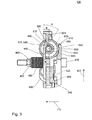
- Fig. 3 shows a partial enlargement of the centrifugal force unit 130 in the region of a centrifugal body 490.
- the first component 430 has a raceway 560 and the second component 440 has a mating track 570.
- the centrifugal force body 490 can roll along the raceway 560 with the first part body 500, ie the larger of the two rollers, while the second part body 510 is in contact with the mating track 570 and can roll along it.
- the second component 440 ie the lower part, in this case has two mutually merging bevels, which are part of the mating track 570.
- the mating track 570 has a first angle portion 580 and a subsequent portion 590 that extends at a different angle from the radial direction 420.
- the track 560 also has a section 600, which adjoins a further section 610.
- the section 600 is associated with the section 580 with respect to the contact points of the centrifugal force bodies 490 during rolling on the track 560 or the mating track 570, while the further section 610 is assigned to the further section 590 of the track 560.
- the section 600 and the further section 610 have the in Fig. 1 to 3 However, shown embodiment of a centrifugal force unit 130 no different angles. More specifically, in this region, the raceway 430 of the upper part or the first component 430 has a planar surface on which the centrifugal force body 490 can roll with the first part body 500. In contrast to this, the second component 440, that is to say the lower part, has rectangular recesses in which the mating track 570 is guided, in which the rolling or slide-supported weight 490 is guided.
- the section 580 of the mating track 570 and the section 600 of the track 560 extend in the axial direction 110 at an angle to each other.
- the section 580 of the mating track 570 and the section 600 of the track 560 approach each other with increasing distance from the axial direction 110, so run towards each other.
- These include an angle A with each other, which is typically greater than an angle B of the further portion 590 of the mating track 570 and the other portion 610 of the track 560 include each other.
- the ratio of the angle of the sections 580 and 600 to the second angle of the further sections 590, 610 is typically at least 3: 1. Frequently, in addition or alternatively, the angle between the sections 580, 600 may be at least 20 °.
- the angle between the further sections 590, 610 may typically be at most 10 °.
- a rapid increase in the distance of the first component 430 from the second component 440 can thus be achieved on the one hand at a start, ie at an increase in the rotational speed of the centrifugal force unit 130 at the beginning, while when exceeding a further limit speed when the or the centrifugal bodies 490 leave the sections 580, 600 and enter the further sections 590, 610, a further enlargement of the distance can be reduced.
- the angle A is 36 °
- the angle B is 7.5 °.
- the use of a portion and another portion of different pitches within the track 560 and mating track 570 also enables hysteresis with respect to the transmittable torque or force acting as a function of the rotational speed of the centrifugal force unit 130. Due to the different angular relationships in the sections 580, 600 compared to the further sections 590, 610, a typically higher engagement speed is thus required, in which the centrifugal body (s) 490 have moved as far along the section 580 or the section 600, the distance of the two components 430, 440 has grown such that the contact force generated along the axial direction 110 by the diaphragm spring 240 or the pressing-force-generating element 230 enables sufficient torque transmission to accelerate the motor vehicle.
- centrifugal force or the body 490 penetrated into the other section 590, 610 they are subject to a lower slope and thus downgrade force caused by the return spring elements 450 only at a lower Auskuppelitchiere to a rolling back of the centrifugal body 490 in the in Fig. 3 shown rest position causes.
- the centrifugal force unit 130 also has an outer radial stop 620 and an inner radial stop 630 with respect to the counterbore 570, which limit movement of the centrifugal body or members 490 to a maximum or a minimum distance value from the axial direction 110.
- the outer radial stop 620 which is also referred to simply as an outer stop, in this case limited in conjunction with the slope of the corresponding track 560 or mating track 570 a maximum distance value of the two components 430, 440 to each other.
- a contact pressure force which is caused by the Anpresskraftfullyden element 230, so for example the diaphragm spring 240, be limited, but it can also be a deformation of these components and thus their mechanical stress are limited.
- this may optionally limit a maximum transmittable torque, so that uncontrolled high torques can not be transmitted even at high rotational speeds of the centrifugal force unit 130 or the clutch 100.
- the inner radial stop 630 can be arranged, for example, such that it ensures that the centrifugal force body or centrifugal bodies 490 are already in contact with the sections 580, 600 of the track 560 and the mating track 570 when the centrifugal force unit 130 is at a standstill.
- a faster response of the centrifugal force unit 130 and / or an improvement in comfort can be achieved, since the centrifugal force bodies 490 are already in a defined position even when the centrifugal force unit 130 is started.
- a noise development from the clutch 100 can be reduced.
- the corresponding stops 620, 630 can also be implemented additionally or additionally in the context of the track 560. In this case, even if they are implemented as part of the mating track 570, they can be implemented as part of the first component 430 or vice versa in the case of an implementation in the context of the track 560 as part of the second component 440. It depends on which of the corresponding part body 500, 510 of the centrifugal body 490 with the respective stops 620, 630 interacts.
- the stops 620, 630 thus limit the path that the weights or centrifugal bodies 490 can travel radially outward along the oblique.
- the centrifugal body 490 thus has the first part body (outer ring), which runs against the flat surface which forms the raceway 560, and whose radial Path is limited by the stops 620 and 630.
- the centrifugal body 490 (weight) also has the second partial body 510, which is roller-mounted or slidably mounted relative to the first partial body 500, which may be, for example, an axis which projects onto the inclined or the section 580 and the further section 590 of the mating track 570 rolls off.
- Fig. 4 shows an enlarged, perspective view of a centrifugal body 490, as it is repeatedly used in the centrifugal force unit 130 shown above according to an embodiment.
- Its partial body 500 and 510 are rotatably supported by the rolling bearing 515 to each other.
- the first part of the body 500 is configured here in the form of a roller with a cylindrical jacket-shaped outer running surface 640, which is in contact with the raceway 560 of the first component 430.
- the outer race 640 extends parallel to an axial direction 650 and a circumferential direction 660 of the first body 500.
- the first partial body 500 shown here also has, in the radial direction, that is to say perpendicular to the axial direction 650 and the circumferential direction 660, a recess 670 provided on both sides of the first partial body 500, through which, for example, a surface on which the first partial body 500 optionally engages could touch second component 440, can be reduced.
- the first part body 500 also has a bore extending centrally to the axial direction 650 into which the roller bearing 515 is inserted, so that it is connected via its outer ring with the first part body.
- the rolling bearing 515 thus enables a rotational movement of the first part body 500 to the second part body 510 about the axial direction 650 around.
- rolling bearing 515 is an encapsulated needle bearing that provides a particularly compact design and provides protection against ingress of solid and liquid contaminants.
- An inner ring of the rolling bearing 515 is connected to the second part body 510.
- This is designed as a cylinder and can be considered as the axis of the first part of body 500.
- the second partial body 510 projects beyond the first partial body 500 in FIG axial direction 650, so that the second part of the body 510 can run in the region of this overhang on the mating track of the second component 440 of the centrifugal unit 130 along with this so in the region of its overhang can be in contact.
- the second part body also has an outer running surface 670 oriented parallel to the outer running surface 640 of the first part body 500 and which is in contact with the mating track 570 of the second component 440 of the centrifugal force unit 130.
- the clutch 100 or the centrifugal force unit 130 it is advisable to differentiate between different operating states. If the engine is off or is just the idling speed, causes the centrifugal force, which also acts on the centrifugal force or weights on the sections 580, 600 of the track 560 and the mating track 570, ie on the steep ramp with the angle A an axial force, which however, smaller than a force caused by the biased coil springs 460 of the return spring members 450. As a result, the first and the second component at their rest value with respect to their distance from each other, so for example, completely held each other.
- the centrifugal force unit 130 can be pressed against the diaphragm spring 240 by some of the coil springs 460 here. They act as lift-off springs here. Due to the described force relationships, however, no force is exerted on the friction pack 120 or on the clutch disc 160, so that the clutch 100 transmits no or at least no relevant torque.
- the axial force acting on the flyweights or centrifugal force body 490 overcomes the force of the coil springs 460 of the return spring elements 450.
- the first component 430 (Upper part) presses against the prestressed diaphragm spring 240 and thereby remains axially largely stationary.
- the second component 440 (lower part) moves in the direction of friction pack 120 and exerts a force that generates or transmits the torque required for starting.
- the contact pressure of the clutch 100 is also practically limited instead of an up to the maximum speed always further substantially square increasing contact pressure.
- the housing so the housing basket 140 and the rolling bearing or centrifugal body 490 can be dimensioned easier and also the maximum transmittable torque is limited to protect the drive train and its other components.
- the centrifugal force by reducing The speed of the centrifugal force unit 130 on the centrifugal force body 490 so low that it is less than the slope forces, which is caused not least by the return spring elements 450 on the shallower ramp with the angle B, which is formed by the other sections 590 and 610 , the weights can roll back from ramp B and immediately rush through the ramp with the Winkle A until they hit their inner radial stop 630.
- the slope force is generated and caused not only by the coil spring force 460 of the return spring members 450, but also by the diaphragm spring 240.
- the use of a clutch 100 with a centrifugal force unit 130 also enables a manual disengage.
- the disengaging unit 150 release mechanism
- the disengaging unit 150 can bring the hydraulic volume required for this purpose, for example via a sniffer bore of the master cylinder, out of a surge tank or into it again submit.
- the use of the sections 580, 600 and the further section 590, 610 with different angles, ie the use of kinked ramps can in this case always allow the same Ausschweg when the clutch has been accelerated once after a start on the Verrastprintiere.
- the clutch 100 according to an embodiment and / or the centrifugal force unit 130 according to one embodiment thus also allows a gear change, ie a disengagement or disconnection of the clutch.
- the disengagement force due to the use of the diaphragm spring 240 or another Anpresskraftbeskybeskybeskybesky element 230 in many cases independent of speed.
- the pressing force typically does not increase quadratically with the rotational speed, and the pressing force can be limited upwardly with respect to the achievable values. As a result, an overload of the drive train or its components can optionally be avoided.
- the Einkuppelwordiere and Auskuppelfitiere can be set differently. Also, in a clutch 100 according to an embodiment, even in sauertouriger driving a slipping same can be avoided.
- the clutch 100 thus provides a centrifugal clutch with a third-party option and a Anpresskraftbegrenzung that can relieve the driver of a motor vehicle by an automatic coupling without having to resort to an electromechanical actuator.
- the coupling 100 was previously described exclusively in connection with the diaphragm spring 240, other types of spring can also be used within the scope of exemplary embodiments of a clutch 100.
- the diaphragm spring 240 can be exchanged for a diaphragm spring.
- Other pressing-force generating elements 230 for example based on one or more coil springs, gas springs or other pneumatic or elastic spring elements can be used here.
- an additional mechanical implementation of a force reduction or interruption may be necessary or advisable here.
- the return spring elements 450 can be implemented for example on the basis of tension springs, disc springs or other pneumatic or elastic spring elements.
Abstract
Description
Ausführungsbeispiele beziehen sich auf eine Fliehkrafteinheit und eine Kupplung, wie sie beispielsweise im Kraftfahrzeugbereich und hier beispielsweise bei Personenkraftwagen sowie im Rennsport eingesetzt werden können.Embodiments relate to a centrifugal force unit and a clutch, as they can be used for example in the automotive sector and here for example in passenger cars and racing.
Die Bedienung einer Kupplung eines Kraftfahrzeugs wird von vielen Fahrern als Belastung, zumindest jedoch als lästig empfunden. Insbesondere bei einem Anfahren, bei dem bei einer konventionellen Trockenkupplung der Schleifpunkt der Kupplung kurzfristig gehalten werden muss, hat bei Fahrern immer wieder das Bedürfnis geweckt, die Bedienung der Kupplung automatisiert erfolgen zu lassen. Gerade in diesem Bereich wurden daher bereits in den 50er-Jahren des letzten Jahrhunderts Fliehkraftkupplungen eingesetzt. So wurde beispielsweise im sogenannten "Saxomat" eine zusätzliche Fliehkraftkupplung eingesetzt, bei der wälzgelagerte Fliehgewichte auf Rampen abrollen und so eine Unterbrechung des Kraftflusses zwischen Motor und Getriebe während des Stillstands des Kraftfahrzeugs ermöglicht haben.The operation of a clutch of a motor vehicle is perceived by many drivers as a burden, but at least as annoying. In particular, when starting, in which the grinding point of the clutch must be kept short in a conventional dry clutch, has repeatedly aroused the need for drivers to make the operation of the clutch automated. For this reason, centrifugal clutches were already being used in this area in the 1950s. Thus, for example, in the so-called "Saxomat" an additional centrifugal clutch was used in which roll-mounted centrifugal weights roll on ramps and so have made it possible to interrupt the power flow between the engine and transmission during standstill of the motor vehicle.
Der Fahrer wird konventionell so über eine Fliehkraftkupplung entlastet, die das Fahrzeug automatisch einkuppelt. Konventionelle Fliehkraftkupplungen basieren hierbei beispielsweise auf radial öffnenden Backen oder Lamellenpaketen, die über Fliehkrafthebel betätigt werden.The driver is conventionally relieved by a centrifugal clutch that automatically engages the vehicle. Conventional centrifugal clutches are based, for example, on radially opening jaws or disk packs, which are actuated via centrifugal levers.
Die
Ausgehend hiervon besteht daher ein Bedarf daran, eine Fliehkrafteinheit für eine Kupplung eines Kraftfahrzeugs zu schaffen, welche ein gezieltes Trennen der Kupplung, beispielsweise für einen Gangwechsel, ermöglicht. Ebenso besteht ein entsprechender Bedarf, eine Kupplung zu schaffen, die einerseits ein gezieltes Trennen der Kupplung für einen Gangwechsel ermöglicht, andererseits jedoch auch durch ein automatisches Einkuppeln beim Anfahren den Fahrer entlastet.Based on this, there is therefore a need to provide a centrifugal force unit for a clutch of a motor vehicle, which allows a targeted disconnection of the clutch, for example, for a gear change. Likewise, there is a corresponding need to provide a clutch that allows one hand, a targeted disconnection of the clutch for a gear change, on the other hand, but also relieved by an automatic engagement when starting the driver.
Diesem Bedarf trägt eine Fliehkrafteinheit für eine Kupplung eines Kraftfahrzeugs gemäß Patentanspruch 1 und eine Kupplung für ein Kraftfahrzeug gemäß Patentanspruch 12 Rechnung.This requirement is borne by a centrifugal force unit for a clutch of a motor vehicle according to claim 1 and a clutch for a motor vehicle according to claim 12.
Ein Fliehkrafteinheit für eine Kupplung eines Kraftfahrzeugs gemäß einem Ausführungsbeispiel umfasst ein erstes Bauteil, ein zweites Bauteil, das bezogen auf eine axiale Richtung drehfest mit dem ersten Bauteil gekoppelt ist, wobei das erste Bauteil und das zweite Bauteil derart ausgebildet sind, dass sich ein Abstand zwischen dem ersten Bauteil und dem zweiten Bauteil entlang der axialen Richtung bei Überschreiten einer Grenzdrehzahl ausgehend von einem Ruhewert bei einem Stillstand der Fliehkrafteinheit vergrößert, und ein Rückstellfederelement, das eine Kraft zwischen dem ersten Bauteil und dem zweiten Bauteil derart bewirkt, dass der Abstand zwischen dem ersten Bauteil und dem zweiten Bauteil bei dem Stillstand der Fliehkrafteinheit den Ruhewert annimmt. Das zweite Bauteil ist hierbei ausgebildet, um mit einer Kupplungsscheibe der Kupplung eine mechanische Verbindung zur Übertragung eines Drehmoments zu schaffen, wobei das erste Bauteil ausgebildet ist, um mit einem anpresskrafterzeugenden Element der Kupplung in Kontakt zu stehen oder in Kontakt gebracht zu werden, sodass durch die Vergrößerung des Abstands zwischen dem ersten Bauteil und dem zweiten Bauteil durch das anpresskrafterzeugende Element die mechanische Verbindung zu der Kupplungsscheibe geschaffen oder verstärkt wird.A centrifugal force unit for a clutch of a motor vehicle according to an embodiment comprises a first component, a second component which is rotationally fixedly coupled to the first component relative to an axial direction, wherein the first component and the second component are formed such that a distance between the first component and the second component along the axial direction when exceeding a limit speed, starting from a rest value at a standstill of the centrifugal unit increases, and a return spring element, which causes a force between the first component and the second component such that the distance between the first Component and the second component at the standstill of the centrifugal unit assumes the quiescent value. The second component is in this case designed to provide with a clutch disc of the clutch a mechanical connection for transmitting a torque, wherein the first component is designed to be in contact with or brought into contact with a anpresskrafterzeugenden element of the clutch the increase in the distance between the first component and the second component is created or reinforced by the Anpresskrafterzeugende element mechanical connection to the clutch disc.
Eine Kupplung für ein Kraftfahrzeug gemäß einem Ausführungsbeispiel umfasst eine Kupplungsscheibe, eine solche Fliehkrafteinheit gemäß Ausführungsbeispiel, ein anpresskrafterzeugendes Element, das so ausgebildet ist, dass bei der Vergrößerung des Abstands des ersten Bauteils von dem zweiten Bauteil der Fliehkrafteinheit eine Anpresskraft entlang der axialen Richtung auf die Fliehkrafteinheit und die Kupplungsscheibe ausgeübt wird, sodass das Drehmoment übertragbar ist, ein Gehäusekorb, der mit dem anpresskrafterzeugenden Element und der Fliehkrafteinheit drehfest verbunden ist, und eine Ausrückeinheit, die derart angeordnet und ausgebildet ist, sodass durch die Ausrückeinheit eine von dem anpresskrafterzeugenden Element ausgeübte Anpresskraft unterdrückbar oder verminderbar ist, sodass die mechanische Verbindung zwischen der Kupplungsscheibe und der Fliehkrafteinheit trennbar ist.A clutch for a motor vehicle according to an embodiment includes a clutch disc, such a centrifugal force unit according to the embodiment, a Anpresskrafterzeugendes element, which is formed so that when increasing the distance of the first component of the second component of the centrifugal force unit, a contact force along the axial direction of the Centrifugal unit and the clutch disc is applied, so that the torque is transferable, a housing basket, which is rotatably connected to the anpresskrafterzeugenden element and the centrifugal force unit, and a disengaging unit, which is arranged and formed so that by the disengaging unit exerted by the anpresskrafterzeugenden element contact pressure can be suppressed or reduced so that the mechanical connection between the clutch disc and the centrifugal force unit is separable.
Einer Fliehkrafteinheit für eine Kupplung gemäß einem Ausführungsbeispiel und einer Kupplung für ein Kraftfahrzeug gemäß einem Ausführungsbeispiel liegt so die Erkenntnis zugrunde, dass ein gezieltes Trennen der Kupplung, beispielsweise für einen Gangwechsel, dadurch erzielbar ist, dass das erste Bauteil der Fliehkrafteinheit derart ausgebildet und angeordnet ist, dass dieses mit dem anpresskrafterzeugenden Element der Kupplung in Kontakt steht oder mit diesem in Kontakt gebracht werden kann, sodass durch die Vergrößerung des Abstands zwischen dem ersten Bauteil und dem zweiten Bauteil die mechanische Verbindung zu der Kupplungsscheibe der Kupplung durch das anpresskrafterzeugende Element derselben geschaffen oder verstärkt wird. Anders ausgedrückt kann bei einer Fliehkrafteinheit gemäß einem Ausführungsbeispiel die Anpresskraft durch das anpresskrafterzeugende Element über das erste Bauteil und das zweite Bauteil der Fliehkrafteinheit auf die Kupplungsscheibe der Kupplung übertragen werden, um so die mechanische Verbindung zur Übertragung des Drehmoments zu schaffen. Noch anders ausgedrückt kann also durch die Vergrößerung des Abstands des ersten und des zweiten Bauteils der Fliehkrafteinheit die Kupplung über das anpresskrafterzeugende Element derselben eingerückt werden.A centrifugal force unit for a clutch according to an embodiment and a clutch for a motor vehicle according to an embodiment is based on the finding that a targeted separation of the clutch, for example for a gear change, can be achieved by the fact that the first component of the centrifugal force unit is designed and arranged in that it is in contact with or can be brought into contact with the pressing force-generating element of the coupling so that, by increasing the distance between the first component and the second component, the mechanical connection to the coupling disc of the coupling is created by the contact force-generating element thereof is reinforced. In other words, in a centrifugal force unit according to an embodiment, the pressing force can be transmitted through the Anpresskrafterzeugende element via the first member and the second component of the centrifugal force unit on the clutch disc of the clutch, so as to provide the mechanical connection for transmitting the torque. In other words, by increasing the distance between the first and the second component of the centrifugal force unit, the clutch can be engaged via the pressing force-generating element of the same.
Die mechanische Verbindung zur Übertragung eines Drehmoments kann hierbei durch Schaffen einer kraftschlüssigen oder reibschlüssigen Verbindung erfolgen. Eine kraftschlüssige oder reibschlüssige Verbindung kommt hierbei durch Haftreibung zustande, die somit eine Normalkraftkomponente zwischen den Verbindungspartner voraussetzt. Die Normalkraftkomponente wird hierbei durch das anpresskrafterzeugende Element der Kupplung in Form der Anpresskraft bewirkt, die vermittelt über das erste Bauteil und die weiteren Komponenten der Fliehkrafteinheit das zweite Bauteil der Fliehkrafteinheit gegen eine Reibfläche der Kupplungsscheibe presst, um so die mechanische Verbindung zur Übertragung des Drehmoments zu schaffen.The mechanical connection for transmitting a torque can be done by creating a frictional or frictional connection. A frictional or frictional connection comes about here by stiction, which thus requires a normal force component between the connection partners. The normal force component is in this case effected by the Anpresskrafterzeugende element of the clutch in the form of the contact force, the mediates via the first component and the other components of the centrifugal force unit, the second component of the centrifugal force unit against a friction surface of the clutch disc, so as to the mechanical connection for transmitting the torque create.
Zu diesem Zweck sind bei Fliehkrafteinheiten gemäß einem Ausführungsbeispiel das erste und/oder das zweite Bauteil häufig im Wesentlichen teller- oder scheibenförmig ausgestaltet. So weist das zweite Bauteil im Allgemeinen an einer der Kupplungsscheibe der Kupplung zugewandten Seite eine Anpressfläche auf, die beispielsweise wenigstens abschnittsweise ring- oder kreisringförmig ausgestaltet ist. Die Anpressfläche ist hierbei häufig im Wesentlichen senkrecht zu der axialen Richtung ausgerichtet.For centrifugal force units according to one embodiment, the first and / or the second component are often configured substantially plate-shaped or disc-shaped for this purpose. Thus, the second component generally has a contact surface on a side facing the clutch disk of the clutch, which contact surface is, for example, at least partially ring-shaped or annular. The contact surface is often oriented substantially perpendicular to the axial direction.
Das erste und das zweite Bauteil können so im zusammengesetzten Zustand wenigstens teilweise ein nicht notwendigerweise abgeschlossenes Gehäuse der Fliehkrafteinheit bilden, wobei das zweite Bauteil der Kupplungsscheibe und das erste Bauteil dem anpresskrafterzeugenden Element zugewandt sind. Entsprechend weist das zweite Bauteil häufig die im Wesentlichen kreisringförmig oder ringförmig ausgebildete Anpressfläche auf, die ausgebildet ist, um mittelbar, beispielsweise über einen aufbringbaren Reibbelag oder eine separate Reibscheibe, oder unmittelbar mit der Kupplungsscheibe in Kontakt bringbar zu sein. Ebenso weist das erste Bauteil typischerweise eine entsprechende Kontaktfläche auf, über die es bei einer Vergrößerung des Abstands zwischen dem ersten und dem zweiten Bauteil mit dem anpresskrafterzeugenden Element der Kupplung in mechanischen Kontakt tritt, um die mechanische Verbindung zu der Kupplungsscheibe zu schaffen oder zu verstärken.The first and the second component can thus form in the assembled state at least partially a not necessarily completed housing of the centrifugal force unit, wherein the second component of the clutch disc and the first component facing the anpresskrafterzeugenden element. Accordingly, the second component often has the substantially annular or annular contact surface, which is designed to be indirectly, for example via an attachable friction lining or a separate friction disc, or directly to be brought into contact with the clutch disc. Likewise, the first component typically has a corresponding contact surface over which, as the distance between the first and second components increases, it mechanically engages the clutch applying element of the clutch to provide or strengthen the mechanical connection to the clutch disc.
Das anpresskrafterzeugende Element der Kupplung ist hierbei häufig derart ausgestaltet, dass dieses eine Anpresskraft entlang der axialen Richtung zwischen dem zweiten Bauteil und der Kupplungsscheibe bewirkt, sodass durch die entstehende Haftreibung des Drehmoment zwischen diesen übertragen werden kann. Genauer gesagt ist das anpresskrafterzeugende Element hierbei häufig so ausgebildet, dass die Anpresskraft zwischen dem zweiten Bauteil und der Kupplungsscheibe erst dann bewirkt oder entsprechend gesteigert wird, wenn das zweite Bauteil aufgrund der Vergrößerung des Abstands zwischen dem ersten Bauteil und dem zweiten Bauteil mit dem anpresskrafterzeugenden Element mechanisch in Wechselwirkung tritt. So kann das anpresskrafterzeugende Element beispielsweise eine Teller- oder Membranfeder umfassen, wobei durch die Vergrößerung des Abstands zwischen dem ersten und dem zweiten Bauteil die Kraft durch eine Deformation der Membran oder Tellerfeder bewirkt wird. Ebenso kann es sich bei dem anpresskrafterzeugenden Element jedoch um eine eine oder mehrere Schraubenfedern umfassende Baueinheit handeln, bei der ebenfalls durch die Vergrößerung des Abstands zwischen dem ersten und dem zweiten Bauteil eine mechanische Deformation der einen oder der mehreren Schraubenfedern bewirkt wird. Ebenso können bei weiteren anpresskrafterzeugenden Elementen gegebenenfalls pneumatische, elastische oder andere mechanische Federelemente zum Einsatz kommen. Anders ausgedrückt, ist das anpresskrafterzeugende Element der Kupplung im Allgemeinen derart ausgebildet, dass durch die Vergrößerung des Abstands zwischen dem ersten und dem zweiten Bauteil die Anpresskraft von dem anpresskrafterzeugenden Element über die Fliehkrafteinheit auf die Kupplungsscheibe übertragen wird bzw. zwischen diesen herrscht. Anders ausgedrückt ist das anpresskrafterzeugende Element derart ausgestaltet, dass es bei der Vergrößerung des Abstands des ersten Bauteils und des zweiten Bauteils der Fliehkrafteinheit die Anpresskraft entlang der axialen Richtung auf die Fliehkrafteinheit und die Kupplungsscheibe ausübt und so das Drehmoment übertragbar macht.The Anpresskrafterzeugende element of the coupling is in this case often designed such that this causes a contact pressure along the axial direction between the second component and the clutch disc, so that can be transmitted by the resulting static friction of the torque between them. More specifically, the abpresskrafterzeugende element is often designed so that the contact force between the second component and the clutch disc is only effected or increased accordingly when the second component due to the increase in the distance between the first component and the second component with the anpresskrafterzeugenden element interacts mechanically. Thus, the Anpresskrafterzeugende element may for example comprise a plate or diaphragm spring, wherein the force is caused by a deformation of the diaphragm or disc spring by increasing the distance between the first and the second component. Likewise, however, the pressing-force-generating element may be a unit comprising one or more coil springs, in which a mechanical deformation of the one or more coil springs is likewise effected by increasing the distance between the first and the second component. Likewise, if necessary, pneumatic, elastic or other mechanical spring elements can be used for further elements which generate force. In other words, the Anpresskrafterzeugende element of the coupling is generally designed such that by increasing the distance between the first and the second component, the contact force is transmitted from the anpresskrafterzeugenden element on the centrifugal force unit on the clutch disc or between them. In other words, the pressing force generating member is configured to exert the pressing force along the axial direction on the centrifugal force unit and the clutch disc as the distance of the first member and the second member of the centrifugal force unit increases, thereby rendering the torque transmissible.
Das anpresskrafterzeugende Element ist ferner hierbei häufig derart ausgebildet, dass die Anpresskraft durch eine weitere mechanische Wechselwirkung unterbrechbar oder zumindest reduzierbar ist. Die weitere mechanische Wechselwirkung kann hierbei beispielsweise von einer Ausrückeinheit bewirkt werden. Im Falle eines anpresskrafterzeugenden Elements, das eine Teller- oder Membranfeder umfasst, kann die Ausrückeinheit die weitere mechanische Wechselwirkung beispielsweise so auf die Membranoder Tellerfeder bewirken, dass diese aufgrund einer Hebelwirkung die Anpresskraft reduziert oder sogar vollständig unterbindet. Auch im Falle der weiteren beschriebenen anpresskrafterzeugenden Elemente, also beispielsweise auf Basis der zuvor beschriebenen, auf Schraubenfedern oder pneumatischen Federelementen beruhenden anpresskrafterzeugenden Elemente, kann durch eine entsprechende Hebelmimik die Anpresskraft durch die weitere mechanische Wechselwirkung reduziert oder vollständig unterbunden werden.The force-generating element is furthermore often designed such that the contact force can be interrupted or at least reduced by a further mechanical interaction. The further mechanical interaction can in this case be effected, for example, by a disengaging unit. In the case of a anpresskrafterzeugenden element comprising a plate or diaphragm spring, the disengagement unit can cause the further mechanical interaction, for example on the diaphragm or disc spring, that this reduces the contact pressure due to a lever action or even completely prevented. Also in the case of the further described anpresskrafterzeugenden elements, so for example based on the previously described, based on coil springs or pneumatic spring elements Anpresskrafterzeugenden elements can be reduced by a corresponding lever mimic the contact force by the further mechanical interaction or completely prevented.
Die axiale Richtung entspricht hierbei im Allgemeinen der Richtung der Drehmomentübertragung und fällt so mit den Rotationsachsen bzw. Wellen der betreffenden Komponenten zusammen. So ist häufig das erste Bauteil, das zweit Bauteil sowie die Kupplungsscheibe und das anpresskrafterzeugende Element im Wesentlichen rotationssymmetrisch ausgestaltet, die eine koaxiale Übertragung des Drehmoments entlang der axialen Richtung, also entlang der gemeinsamen Achsen ermöglichen.The axial direction generally corresponds to the direction of the torque transmission and coincides with the axes of rotation or waves of the relevant components. So is often the first component, the second component and the Clutch disc and the anpresskrafterzeugende element configured substantially rotationally symmetrical, which allow a coaxial transmission of torque along the axial direction, ie along the common axes.
Das Rückstellfederelement kann hierbei derart ausgeführt sein, dass dieses eine Kraft zwischen dem ersten Bauteil und dem zweiten Bauteil mit einer solchen Stärke bewirkt, dass erst bei einem Überschreiten der Grenzdrehzahl sich der Abstand der zwischen dem ersten Bauteil und dem zweiten Bauteil entlang der axialen Richtung vergrößert.The return spring element can in this case be designed such that this causes a force between the first component and the second component with such a strength that increases only when exceeding the limit speed, the distance between the first component and the second component along the axial direction ,
Bei einer Fliehkrafteinheit gemäß einem Ausführungsbeispiel können das erste Bauteil und das zweite Bauteil ferner derart ausgebildet sein, dass sich der Abstand zwischen dem ersten Bauteil und dem zweiten Bauteil entlang der axialen Richtung bei einem Überschreiten einer weiteren Grenzdrehzahl bei einer weiter steigenden Drehzahl weniger stark vergrößert. Hierdurch kann es beispielsweise möglich sein, eine Vergrößerung der Abmessungen der Fliehkrafteinheit entlang der axialen Richtung zu beschränken und so beispielsweise die von dem anpresskrafterzeugenden Element erzeugte Anpresskraft und/oder eine mechanische Deformation desselben zu begrenzen. Ebenso kann es hierdurch möglich sein, eine Drehzahl, bei der eine Kupplung mit einer Fliehkrafteinheit gemäß einem Ausführungsbeispiel einkuppelt von einer Drehzahl, bei der die betreffende Kupplung mit der Fliehkrafteinheit wieder auskuppelt, unterschiedlich auszugestalten. Hierdurch kann es beispielsweise möglich werden, eine Hysterese hinsichtlich der übertragbaren Drehmomente bzw. hinsichtlich der Anpresskraft, die häufig linear zueinander verlaufen, zu bewirken, sodass eine Einkuppeldrehzahl, bei der die Kupplung schließt, höher sein kann als eine Auskuppeldrehzahl, bei der die Kupplung wieder trennt bzw. öffnet.In a centrifugal force unit according to an exemplary embodiment, the first component and the second component can also be designed such that the distance between the first component and the second component along the axial direction increases less when exceeding a further limit speed at a further increasing speed. As a result, it may be possible, for example, to limit an increase in the dimensions of the centrifugal force unit along the axial direction and thus to limit, for example, the contact force generated by the contact force generating element and / or a mechanical deformation thereof. Likewise, it may thereby be possible to design a speed at which engages a clutch with a centrifugal force unit according to an embodiment of a speed at which disengages the respective clutch with the centrifugal force unit again, different. This makes it possible, for example, to effect a hysteresis with regard to the transmittable torques or with regard to the contact force, which frequently run linearly relative to one another, so that an engagement speed at which the clutch closes can be higher than a declutching speed at which the clutch is again engaged separates or opens.
Bei einer Fliehkrafteinheit gemäß einem Ausführungsbeispiel können so das erste Bauteil eine Laufbahn und das zweite Bauteil eine Gegenlaufbahn für einen Fliehkraftkörper aufweisen, wobei die Laufbahn und die Gegenlaufbahn sich entlang einer radialen Richtung an dem ersten Bauteil und dem zweiten Bauteil erstrecken und wobei die Laufbahn und die Gegenlaufbahn jeweils einen Abschnitt aufweisen, die in Richtung der axialen Richtung schräg zueinander verlaufen. Der Abschnitt der Laufbahn und der Abschnitt der Gegenlaufbahn laufen hierbei mit zunehmendem Abstand von der axialen Richtung aufeinander zu. Der Fliehkörper ist hierbei derart ausgebildet, um sich bei einer Drehung der Fliehkrafteinheit um die axiale Richtung aufgrund einer auf ihn einwirkenden Fliehkraft entlang der Laufbahn und der Gegenlaufbahn zu bewegen. Die radiale Richtung erstreckt sich hierbei im Wesentlichen senkrecht zu der axialen Richtung. Hierbei wird die Vergrößerung des Abstands von dem ersten Bauteil zu dem zweiten Bauteil folglich über die beschriebene geometrische Ausgestaltung der Laufbahn und der Gegenlaufbahn und dem zwischen diesen beweglich angeordneten Fliehkraftkörper bewirkt. Die Übertragung der Anpresskraft von dem ersten Bauteil zu dem zweiten Bauteil und weiter zu der Kupplungsscheibe verläuft hierbei in axialer Richtung im Wesentlichen auch über den Fliehkraftkörper.In a centrifugal force unit according to an embodiment, the first component may thus comprise a raceway and the second component a mating track for a centrifugal body, wherein the raceway and the mating track extend along a radial direction on the first component and the second component and wherein the raceway and the Mating track each having a portion which extend obliquely to each other in the direction of the axial direction. The section of the track and the Section of the mating track run towards each other with increasing distance from the axial direction. The centrifugal body is in this case designed in such a way as to move along a rotational path of the centrifugal force unit about the axial direction due to a centrifugal force acting on it along the track and the mating track. The radial direction in this case extends substantially perpendicular to the axial direction. In this case, the enlargement of the distance from the first component to the second component is consequently effected via the described geometric configuration of the raceway and the mating track and the centrifugal force body arranged movably between them. The transmission of the contact pressure of the first component to the second component and on to the clutch disc in this case extends in the axial direction substantially also on the centrifugal body.
Bei anderen Ausführungsbeispielen können natürlich entsprechend eine Mehrzahl von Laufbahnen, Gegenlaufbahnen und Fliehkraftkörpern implementiert sein. So kann beispielsweise eine Fliehkrafteinheit sechs Laufbahnen, sechs Gegenlaufbahnen und sechs Fliehkraftkörper, jedoch auch jede andere Anzahl von Laufbahnen, Gegenlaufbahnen und Fliehkraftkörpern aufweisen.Of course, in other embodiments, a plurality of raceways, mating tracks, and centrifugal bodies may be implemented accordingly. For example, a centrifugal unit may have six raceways, six mating tracks and six centrifugal bodies, but also any other number of raceways, mating tracks and centrifugal bodies.
Bei einer solchen Fliehkrafteinheit können die Laufbahn und die Gegenlaufbahn ferner jeweils einen weiteren Abschnitt aufweisen, die entlang der radialen Richtung mit wachsendem Abstand zu der axialen Richtung hinter den Abschnitten der Laufbahn und der Gegenlaufbahn angeordnet sind. Die weiteren Abschnitte der Laufbahn und der Gegenlaufbahn können hierbei schräg zueinander mit einem kleineren Winkel als die Abschnitte der Laufbahn und der Gegenlaufbahn zueinander verlaufen. Der weitere Abschnitt der Laufbahn und der weitere Abschnitt der Gegenlaufbahn laufen hierbei mit zunehmendem Abstand von der axialen Richtung aufeinander zu. Hierdurch kann die zuvor beschriebene Reduzierung der Vergrößerung des Abstands des ersten Bauteils und des zweiten Bauteils erzielt werden, wenn die Drehzahl der Fliehkrafteinheit die weitere Grenzdrehzahl übersteigt.Further, in such a centrifugal force unit, the raceway and the mating track may each have another portion disposed along the radial direction with increasing distance to the axial direction behind the portions of the raceway and the mating track. The further sections of the raceway and the mating track may in this case run obliquely to each other at a smaller angle than the sections of the raceway and the mating track to each other. The further section of the raceway and the further section of the mating track run towards each other with increasing distance from the axial direction. As a result, the above-described reduction of the increase in the distance between the first component and the second component can be achieved if the rotational speed of the centrifugal force unit exceeds the further limit rotational speed.
Bei einer solchen Fliehkrafteinheit kann das Verhältnis der Winkel zwischen den Abschnitten und den weiteren Abschnitten der Laufbahn und der Gegenlaufbahn wenigstens 3:1 und/oder der Winkel zwischen den weiteren Abschnitten der Laufbahn und der Gegenlaufbahn höchstens 10° und/oder der Winkel zwischen den Abschnitten der Laufbahn und der Gegenlaufbahn wenigstens 20° betragen. Durch die Implementierung einer oder mehrerer dieser konstruktiven Ausgestaltungen kann so beispielsweise die Einkuppeldrehzahl und/oder die Auskuppeldrehzahl derart eingestellt werden, dass eine Kupplung mit einer Fliehkrafteinheit gemäß einem Ausführungsbeispiel auch bei einer untertourigen Fahrweise nicht notwendigerweise rutscht.In such a centrifugal force unit, the ratio of the angles between the sections and the further sections of the track and the mating track at least 3: 1 and / or the angle between the other sections of the track and the mating track at most 10 ° and / or the angle between the sections of the track and the mating track at least 20 °. By implementing one or more of these structural configurations, for example, the engagement speed and / or the disengagement speed can be adjusted such that a clutch with a centrifugal force unit according to an exemplary embodiment does not necessarily slip even with a low-speed driving style.
Bei einer Fliehkrafteinheit gemäß einem Ausführungsbeispiel können die Laufbahn und/oder die Gegenlaufbahn einen äußeren radialen Anschlag aufweisen, der eine Bewegung des oder der Fliehkraftkörper entlang der radialen Richtung auf einen maximalen Abstandswert von der axialen Richtung begrenzt. Hierdurch wird im Zusammenspiel mit den Neigungen der Abschnitte bzw. der weiteren Abschnitte der Laufbahn und der Gegenlaufbahn ein maximaler Abstandswert definiert, der einerseits eine maximale Anpresskraft und/oder andererseits eine maximale Deformation des anpresskrafterzeugenden Elements oder seiner Komponenten beschränkt. Hierdurch kann so ein maximal übertragbares Drehmoment und/oder eine mechanische Belastung des anpresskrafterzeugenden Elements oder anderer Komponenten einer entsprechenden Kupplung beschränkt werden.In a centrifugal force unit according to an embodiment, the raceway and / or mating track may include an outer radial stop limiting movement of the centrifugal force body (s) along the radial direction to a maximum distance value from the axial direction. As a result, a maximum distance value is defined in interaction with the inclinations of the sections or the further sections of the track and the mating track, which limits on the one hand a maximum contact pressure and / or on the other hand, a maximum deformation of the anpresskrafterzeugenden element or its components. As a result, a maximum transferable torque and / or a mechanical load of the Anpresskrafterzeugenden element or other components of a corresponding coupling can be limited.
Bei einer Fliehkrafteinheit gemäß einem Ausführungsbeispiel können die Laufbahn und/oder die Gegenlaufbahn ferner einen inneren radialen Anschlag aufweisen, der eine Bewegung des oder der Fliehkraftkörper entlang der radialen Richtung auf einen minimalen Abstandswert zu der axialen Richtung derart begrenzt, dass der oder die Fliehkraftkörper bei dem Stillstand der Fliehkrafteinheit bereits mit den Abschnitten der Laufbahn und der Gegenlaufbahn in Kontakt stehen. Hierdurch kann gegebenenfalls ein Anfahrverhalten einer Kupplung mit einer Fliehkrafteinheit gemäß einem Ausführungsbeispiel dadurch verbessert werden, dass der oder die Fliehkraftkörper bereits mit dem geneigten Abschnitt in Kontakt stehen, sodass unmittelbar durch eine Veränderung der Drehzahl der Fliehkrafteinheit eine Veränderung des Abstands des ersten und des zweiten Bauteils der Fliehkrafteinheit einhergehen, ohne dass der oder die Fliehkraftkörper zunächst zu dem entsprechenden Abschnitt gelangen müssen. Hierdurch kann gegebenenfalls auch eine Geräuschentwicklung positiv beeinflusst werden, da auch bei sehr niedrigen Drehzahlen der Fliehkrafteinheit der oder die Fliehkraftkörper sich in einer definierten Position zwischen dem inneren radialen Anschlag und dem Abschnitt der Laufbahn bzw. der Gegenlaufbahn befinden.In a centrifugal force unit according to an embodiment, the raceway and / or mating track may further comprise an inner radial stop limiting movement of the centrifugal force body (s) along the radial direction to a minimum distance to the axial direction such that the centrifugal force body (s) in the Standstill of the centrifugal unit already in contact with the sections of the raceway and the mating track. In this way, if appropriate, a starting behavior of a clutch with a centrifugal force unit can be improved according to an exemplary embodiment in that the centrifugal force element or bodies are already in contact with the inclined section, so that a change in the rotational speed of the centrifugal force unit results in a change in the distance between the first and second components Accompany the centrifugal force unit, without that or the centrifugal body must first reach the corresponding section. As a result, if necessary, a noise development can be positively influenced, since even at very low speeds of the centrifugal force unit or the centrifugal body in a defined position between the inner radial stop and the portion of the raceway and the mating track are located.
Bei einer Fliehkrafteinheit gemäß einem Ausführungsbeispiel kann der Fliehkraftkörper einen ersten und einen zweiten im Wesentlichen rotationssymmetrischen Teilkörper umfassen, wobei der erste Teilkörper mit der Laufbahn und der zweite Teilkörper mit der Gegenlaufbahn in Kontakt stehen. Der erste und der zweite Teilkörper sind hierbei zueinander über ein Gleitlager oder ein Wälzlager, beispielsweise ein Nadellager gelagert. Hierdurch kann es gegebenenfalls möglich sein, eine reibungsärmere Übermittlung der Anpresskraft über die Fliehkrafteinheit zu bewirken, da sich die beiden Teilkörper des oder der Fliehkraftkörper aufgrund ihrer rotationssymmetrischen Ausgestaltung und ihrer Lagerung reibungsärmer zwischen der Laufbahn und der Gegenlaufbahn der Fliehkrafteinheit bewegen können. Hierdurch kann gegebenenfalls ein Ansprechverhalten der Fliehkrafteinheit und damit einer Kupplung mit einer solchen Fliehkrafteinheit gemäß einem Ausführungsbeispiel ebenso wie eine Energieeffizienz und damit ein Wirkungsgrad der Kupplung verbessert werden.In a centrifugal force unit according to one embodiment, the centrifugal body may comprise a first and a second substantially rotationally symmetrical part body, wherein the first part body with the raceway and the second part body are in contact with the mating track. The first and the second part of the body are in this case mounted to each other via a sliding bearing or a rolling bearing, for example a needle bearing. This may possibly make it possible to effect a lower friction transmission of the contact force on the centrifugal force unit, since the two body parts of the centrifugal body or can move due to their rotationally symmetrical design and storage friction between the career and the mating track of the centrifugal force unit. In this way, optionally, a response of the centrifugal force unit and thus a clutch with such a centrifugal force unit according to an embodiment as well as energy efficiency and thus an efficiency of the clutch can be improved.
Bei einer Fliehkrafteinheit gemäß einem Ausführungsbeispiel kann bei einem Betriebszustand der Fliehkraftkörper wenigstens teilweise in radialer Richtung außerhalb der Kupplungsscheibe angeordnet sein. Anders ausgedrückt, kann der oder können die Fliehkraftkörper bezogen auf die Kupplungsscheibe in radialer Richtung nach außen versetzt angeordnet sein. Hierdurch kann gegebenenfalls eine Kupplung mit einer Fliehkrafteinheit implementiert werden, die keinen oder nur einen geringfügigen Zuwachs hinsichtlich ihrer axialen Ausdehnung im Vergleich zu einer konventionellen Kupplung erfährt. Eine solche Kupplung kann beispielsweise bei Anwendungen zum Einsatz kommen, bei denen gerade der axiale Bauraum ein entscheidendes Kriterium darstellt. So kann eine solche Kupplung mit einer entsprechenden Fliehkrafteinheit gemäß einem Ausführungsbeispiel beispielsweise bei Kleinwagen oder anderen Kraftfahrzeugen zum Einsatz kommen, bei denen der Motor und/oder das Getriebe quer zur Fahrtrichtung eingebaut sind.In a centrifugal force unit according to an exemplary embodiment, in an operating state, the centrifugal force body can be arranged at least partially in the radial direction outside the clutch disc. In other words, the centrifugal force body or may be arranged offset in the radial direction with respect to the clutch disc outwards. This may optionally implement a clutch with a centrifugal force unit that experiences no or only a slight increase in its axial extent compared to a conventional clutch. Such a coupling can be used, for example, in applications in which just the axial space is a decisive criterion. Thus, such a clutch can be used with a corresponding centrifugal force unit according to an embodiment example in small cars or other motor vehicles, in which the engine and / or the transmission are installed transversely to the direction of travel.
Bei einer Fliehkrafteinheit gemäß einem Ausführungsbeispiel kann der Fliehkraftkörper oder können die Fliehkraftkörper unter allen Betriebszuständen nicht oder um nicht mehr als einen größten Radius des Fliehkraftkörpers oder der Fliehkraftkörper über die Kupplungsscheibe in radialer Richtung hervorstehen. Anders ausgedrückt können bei einer solchen Fliehkrafteinheit der oder die Fliehkraftkörper in axialer Richtung zu der Kupplungsscheibe angeordnet sein, was beispielsweise bei Anwendungsszenarien von Vorteil sein kann, bei denen gerade der radiale Bauraum ein entscheidendes Kriterium darstellt. Gerade im Bereich des Rennsports kann es beispielsweise von Vorteil sein, eine entsprechende Anordnung des oder der Fliehkraftkörper im Inneren der Fliehkrafteinheit zu wählen. Darüber hinaus kann es gegebenenfalls auch möglich sein, die Fliehkrafteinheit in einem solchen Fall konstruktiv zu vereinfachen, da die auftretenden Kräfte nicht mehr entlang der radialen Richtung zu einem Punkt außerhalb des Durchmessers der Kupplungsscheibe übertragen werden müssen, sodass gegebenenfalls auftretende Biegemomente der Bauteile und Komponenten der Fliehkrafteinheit reduzierbar sein können.In a centrifugal force unit according to an embodiment, the centrifugal body or the centrifugal body can not or in all operating conditions no more than a largest radius of the centrifugal body or the centrifugal body protrude beyond the clutch disc in the radial direction. In other words, in such a centrifugal force unit, the centrifugal body or centrifugal bodies may be arranged in the axial direction of the clutch disc, which may be advantageous, for example, in application scenarios in which the radial installation space is a decisive criterion. Especially in the field of racing, it may be advantageous, for example, to choose a corresponding arrangement of the centrifugal force or the body in the interior of the centrifugal force unit. In addition, it may also be possible to simplify the design of the centrifugal force unit in such a case, since the forces occurring no longer have to be transmitted along the radial direction to a point outside the diameter of the clutch disc, so that possibly occurring bending moments of the components and components Centrifugal unit can be reduced.
Eine Fliehkrafteinheit gemäß einem Ausführungsbeispiel kann hierbei derart ausgebildet sein, dass sie in einem Gehäusekorb mit einem anpresskrafterzeugenden Element einsetzbar ist, das so ausgebildet ist, dass es bei der Vergrößerung des Abstands des ersten Bauteils von dem zweiten Bauteil der Fliehkrafteinheit eine Anpresskraft entlang der axialen Richtung auf die Fliehkrafteinheit und die Kupplungsscheibe ausübt, sodass das Drehmoment übertragbar wird. So kann eine Fliehkrafteinheit gemäß einem Ausführungsbeispiel beispielsweise als Druckplatte einer Kraftfahrzeugkupplung, beispielsweise einer Einscheiben-Trockenkupplung sein. Ebenso kann sie jedoch auch im Zusammenhang mit einem Reibpaket mit mehr als einer Kupplungsscheibe und/oder einer Mehrzahl von Innen- und Außenlamellen zum Einsatz kommen, wie sie beispielsweise im Bereich des Rennsports aber auch bei anderen Kupplungen zum Einsatz kommt, bei denen eine betragsmäßig große Drehmomentübertragung gefordert ist.A centrifugal force unit according to an exemplary embodiment may in this case be designed such that it can be inserted in a housing basket with a pressure-force-generating element which is designed so that it increases the distance of the first component from the second component of the centrifugal force unit by a contact force along the axial direction on the centrifugal force unit and the clutch disc exerts, so that the torque is transferable. Thus, a centrifugal force unit according to one embodiment, for example, as a pressure plate of a motor vehicle clutch, for example, a single-disc dry clutch. Likewise, however, it can also be used in connection with a friction pack with more than one clutch disk and / or a plurality of inner and outer disks, as used, for example, in the field of racing but also in other clutches in which an amount is large Torque transmission is required.
Bei einer Kupplung gemäß einem Ausführungsbeispiel kann die Fliehkrafteinheit zumindest in einem verschleißfreien Zustand stets mit dem anpresskrafterzeugenden Element in Kontakt stehen. Hierdurch kann gegebenenfalls ein Ansprechverhalten der Fliehkrafteinheit gegenüber einer Lösung verbessert werden, bei der zunächst ein Abstand zu dem anpresskrafterzeugenden Element überwunden werden muss, bevor die Anpresskraft an die Kupplungsscheibe übertragen werden kann.In a clutch according to one embodiment, the centrifugal force unit can always be in contact with the Anpresskrafterzeugenden element at least in a wear-free state. In this way, if appropriate, a response of the centrifugal force unit can be improved compared to a solution in which initially a distance must be overcome to the anpresskrafterzeugenden element before the contact pressure can be transmitted to the clutch disc.
Bei einer Kupplung gemäß einem Ausführungsbeispiel kann das anpresskrafterzeugende Element eine Teller- oder Membranfeder umfassen, die in einem vorgespannten Zustand in dem Gehäusekorb angeordnet ist. Hierdurch kann bereits bei einer geringeren Vergrößerung des Abstands des ersten Bauteils von dem zweiten Bauteil der Fliehkrafteinheit aufgrund der Vorspannung einer größere Anpresskraft an die Kupplungsscheibe übertragen und damit eine Drehmomentübertragung erhöht werden.In a clutch according to an embodiment, the Anpresskrafterzeugende element may comprise a plate or diaphragm spring, which is arranged in a prestressed state in the housing basket. As a result, even with a smaller increase in the distance of the first component from the second component of the centrifugal force unit due to the bias of a larger contact force transmitted to the clutch disc and thus a torque transmission can be increased.
Bei einer Kupplung gemäß einem Ausführungsbeispiel kann die Ausrückeinheit ein Vorspannfederelement aufweisen, das derart ausgebildet und angeordnet ist, dass die Ausrückeinheit stets mit dem anpresskrafterzeugenden Element derart in Kontakt steht, dass die Ausrückeinheit die mechanische Verbindung im Wesentlichen zeitlich unmittelbar zwischen der Kupplungsscheibe und der Fliehkrafteinheit trennbar macht. Hierdurch kommt es also bei einer Betätigung der Ausrückeinheit im Wesentlichen zeitlich unmittelbar zu der weiteren mechanischen Wechselwirkung mit dem anpresskrafterzeugenden Element, was zu einer Reduzierung der Anpresskraft und damit zu einer Reduzierung oder sogar zu einem Trennen der Drehmomentübertragung führen kann. Ein gegebenenfalls vom Betriebszustand der Kupplung bzw. der Fliehkrafteinheit abhängiges Spiel muss so gegebenenfalls nicht erst überwunden werden. Hierdurch kann ein Gangwechsel gegebenenfalls verschleißärmer und reproduzierbarer durchgeführt werden, da eine Trennung der Drehmomentübertragung, also ein Auskuppeln unter definierteren Bedingungen erfolgen kann.In a clutch according to an embodiment, the disengagement unit may comprise a biasing spring element which is designed and arranged such that the disengaging unit is always in contact with the pressing force generating member such that the disengaging unit can substantially disconnect the mechanical connection directly between the clutch disc and the centrifugal force unit power. As a result, when the release unit is actuated, it is substantially directly in time to the further mechanical interaction with the pressure-force-generating element, which can lead to a reduction of the contact force and thus to a reduction or even to a disconnection of the torque transmission. An optionally dependent on the operating state of the clutch or the centrifugal unit game must not be overcome so if necessary. As a result, a gear change may possibly be carried out with less wear and reproducibility, since a separation of the torque transmission, that is to say disengaging, can take place under more defined conditions.
Ausführungsbeispiele werden unter Bezugnahme auf die beiliegenden Figuren näher beschrieben und erläutert.
- Fig. 1
- zeigt eine Querschnittsdarstellung einer Kupplung gemäß einem Ausführungsbeispiel mit einer Fliehkrafteinheit gemäß einem Ausführungsbeispiel als Explosionsdarstellung;
- Fig. 2
- zeigt eine Querschnittsdarstellung einer Kupplung mit einer Fliehkrafteinheit gemäß einem Ausführungsbeispiel;
- Fig. 3
- zeigt eine Detailvergrößerung der Fliehkrafteinheit gemäß einem Ausführungsbeispiel im Bereich der Fliehkraftkörper ; und
- Fig. 4
- zeigt eine perspektivische Darstellung eines Fliehkraftkörpers der Fliehkrafteinheit.
- Fig. 1
- shows a cross-sectional view of a coupling according to an embodiment with a centrifugal force unit according to an embodiment in an exploded view;
- Fig. 2
- shows a cross-sectional view of a coupling with a centrifugal force unit according to an embodiment;
- Fig. 3
- shows an enlarged detail of the centrifugal force unit according to an embodiment in the field of centrifugal force; and
- Fig. 4
- shows a perspective view of a centrifugal body of the centrifugal force unit.
Im Rahmen der vorliegenden Beschreibung werden zusammenfassende Bezugszeichen für Objekte, Strukturen und andere Komponenten verwendet werden, wenn die betreffende Komponente an sich oder mehrerer entsprechende Komponenten innerhalb eines Ausführungsbeispiels oder innerhalb mehrerer Ausführungsbeispiele beschrieben werden. Passagen der Beschreibung, die sich auf eine Komponente beziehen, sind daher auch auf andere Komponenten in anderen Ausführungsbeispielen übertragbar, soweit dies nicht explizit ausgeschlossen ist oder sich dies aus dem Zusammenhang ergibt. Werden einzelne Komponenten bezeichnet, werden individuelle Bezugszeichen verwendet, die auf den entsprechenden zusammenfassenden Bezugszeichen basieren. Bei der nachfolgenden Beschreibung von Ausführungsformen bezeichnen daher gleiche Bezugszeichen gleiche oder vergleichbare Komponenten.In the context of the present description, summary reference numbers for objects, structures, and other components will be used when describing the component in question itself or more corresponding components within one embodiment or within several embodiments. Passages of the description which refer to one component are therefore also transferable to other components in other embodiments, unless this is explicitly excluded or if this results from the context. When referring to individual components, individual reference numerals based on the corresponding summary reference numbers are used. In the following description of embodiments, therefore, the same reference numerals designate the same or similar components.
Komponenten, die mehrfach in einem Ausführungsbeispiel oder in unterschiedlichen Ausführungsbeispielen auftreten, können hierbei bezüglich einiger ihrer technischen Parameter identisch und/oder unterschiedlich ausgeführt oder implementiert werden. Es ist so beispielsweise möglich, dass mehrere Komponenten innerhalb eines Ausführungsbeispiels bezüglich eines Parameters identisch, bezüglich eines anderen Parameters jedoch unterschiedlich ausgeführt sein können.Components which occur multiple times in one exemplary embodiment or in different exemplary embodiments may in this case be embodied identically and / or differently with respect to some of their technical parameters or implemented. It is thus possible, for example, for several components within an exemplary embodiment to be identical with respect to one parameter, but differently with respect to another parameter.
Während die Fliehkrafteinheit 130 insbesondere im Zusammenhang mit den
Das Reibpaket 120 umfasst eine Kupplungsscheibe 160, die eine Mehrzahl von Innenlamellen 170-1, 170-2 aufweist. Die Innenlamellen 170 sind hierbei verdrehfest mit der Kupplungsscheibe verbunden, können jedoch gegebenenfalls entlang der axialen Richtung 110 verschiebbar sein. Die Kupplungsscheibe 160 weist ferner eine Nabe 180 auf, mit deren Hilfe die Kupplungsscheibe 160 mit einer Getriebeeingangswelle oder einer anderen Welle drehfest verbindbar ist. Die Kupplungsscheibe 160 ist entsprechend im Wesentlichen rotationssymmetrisch zu der axialen Richtung 110 ausgerichtet.The
Das Reibpaket 120 umfasst ferner eine Mehrzahl von Außenlamellen 190-1, 190-2 und 190-3 die derart angeordnet und ausgebildet sind, dass sie jeweils abwechselnd mit den Innenlamellen 170 in Kontakt bringbar sind. Die Außenlamellen 190 sind hierbei über den Gehäusekorb 140 zueinander verdrehfest, jedoch in axialer Richtung 110 einander verschiebbar angeordnet. Die Innenlamellen 170 und die Außenlamellen 190 können hierbei optional teilweise oder vollständig einen Reibbelag aufweisen, sodass ein Haftreibungskoeffizient zwischen den Außenlamellen 190 und den Innenlamellen bei Anliegen einer entlang der axialen Richtung 110 wirkenden Anpresskraft gegenüber entsprechenden Innen- und Außenlamellen 170, 190 ohne einen entsprechenden Reibbelag gegebenenfalls erhöht werden kann.The
Der Gehäusekorb 140 ist hierbei derart ausgebildet, dass dieser nicht nur die Außenlamellen 190, sondern auch die Fliehkrafteinheit 130 verdrehfest, jedoch axial verschiebbar, also entlang der axialen Richtung 110 verschiebbar aufnimmt. Zu diesem Zweck weist der Gehäusekorb 140 eine Mehrzahl stabförmiger Elemente 200 auf, mit deren Hilfe die Außenlamellen 190 über entsprechende Ausnehmungen 210, beispielsweise Laschen, verdrehfest mit dem Gehäusekorb 140 koppelbar sind.The
Je nach konkreter Ausgestaltung des Gehäusekorbs 140 können die stabförmigen Elemente 200, gegebenenfalls jedoch auch andere Elemente des Gehäusekorbs 140 Bohrungen 220 oder anderen Befestigungsstrukturen umfassen, mit deren Hilfe der Gehäusekorb 140 mit einem Schwungrad eines Motors oder einer anderen angetriebenen Komponente mechanisch drehfest verbindbar ist. Bei dem in
Der Gehäusekorb 140 weist ein anpresskrafterzeugendes Element 230 in Form einer in dem Gehäusekorb 140 eingenieteten und vorgespannten Membranfeder 240 auf. Die Membranfeder 240 ist hierbei über zwei als Drahtringe ausgeführte Kippringe 250 vorgespannt in dem Gehäusekorb 140 angeordnet. Genauer gesagt, ist die Membranfeder 240 hierbei über einen Befestigungsring 260 mit dem Gehäusekorb 140 vernietet.The
Die Ausrückeinheit 150 weist ein Gehäuse 270 mit einem Hydraulikanschluss 280 und einer Ausnehmung 290 auf, die den Arbeitsraum 300 der Ausrückeinheit 150 bildet. Das Gehäuse 270 wird auch als Nehmerzylinder bezeichnet.The disengaging
In der Ausnehmung 290 ist ein Kolben 310 angeordnet, der in zwei ringförmig ausgestalteten Nute 320 jeweils ein Dichtelement 330 in Form eines O-Rings aufweist. Die beiden O-Ringe bzw. Dichtelemente 330 dichten hierbei den Arbeitsraum 300 gegen ein Austreten von Hydraulikflüssigkeit aus dem Arbeitsraum 300 ab. Der Kolben 310 ist mit einem Außenring 340 eines Wälzlagers 350 verbunden, bei dem es sich bei dem in
Zwischen dem Gehäuse 270 und dem Kolben 310 ist ferner ein Vorspannfederelement 390, das auch als Vorlastfeder oder Vorspannfeder bezeichnet wird, angeordnet und auf Druck entlang der axialen Richtung 110 vorgespannt. Das Vorspannfederelement 390 ist hierbei in einer Nut 400 in dem Gehäuse 270 und in einer entsprechenden Gegennut 410 des Gehäuses 270 angeordnet, sodass das Vorspannfederelement 390 gegen ein Verrutschen senkrecht zu der axialen Richtung 110, also entlang einer radialen Richtung 420 gesichert ist.Between the
Die Ausrückeinheit 150 bzw. ihr Vorspannfederelement 390 sind hierbei derart ausgebildet und angeordnet, dass die Ausrückeinheit 150 stets mit dem anpresskrafterzeugenden Element 230, also der Membranfeder 240 in Kontakt steht. Hierdurch kann die Ausrückeinheit 150 die mechanische Verbindung unmittelbar zwischen der Kupplungsscheibe 160 und der Fliehkrafteinheit 130 trennen, wie dies im Zusammenhang mit
Die in
Die Rückstellfederelemente 450 der Fliehkrafteinheit 130 aus
Die zuvor beschriebene, von dem Rückstellfederelement 450 ausgeübte Kraft zwischen dem ersten und dem zweiten Bauteil 430, 440 wird bei dem in
Wie im Zusammenhang mit
Die Anzahl der Fliehkraftkörper 490 kann hierbei grundsätzlich beliebig gewählt werden. So kann bei einer Fliehkrafteinheit 130 gegebenenfalls bereits der Einsatz eines einzigen entsprechenden Fliehkraftkörpers 490 genügen. Bei anderen Ausführungsbeispielen kann es jedoch ratsam sein, schon um eine radialsymmetrische Gewichtsverteilung zu erzielen, mehr als einen, beispielsweise zwei oder mehrere Fliehkraftkörper 490 einzusetzen. Bei dem in
Durch den Einsatz der zuvor kurz beschriebenen Laufbahnen und Gegenlaufbahnen, zwischen denen die Fliehkraftkörper 490 laufen, sind das zweite Bauteil 440 und das erste Bauteil 430 folglich derart ausgebildet, dass sich ein Abstand zwischen diesen beiden Bauteilen 430, 440 entlang der axialen Richtung 110 bei einem Überschreiten einer Grenzdrehzahl ausgehend von einem Ruhewert bei einem Stillstand der Fliehkraft 130 vergrößert. Die Grenzdrehzahl hängt hierbei beispielsweise von einer durch die Schraubenfedern 460 der Rückstellfederelemente 450 bewirkten Kraft ab. Bei anderen Ausführungsbeispielen kann diese Funktionalität jedoch auch ohne den Einsatz von Fliehkraftkörpern 490 umgesetzt werden, indem beispielsweise Kniehebelkonstruktionen zum Einsatz kommen.By using the previously briefly described raceways and mating tracks, between which the
Die Fliehkraftkörper 490 weisen einen ersten Teilkörper 500 und einen zweiten Teilkörper 510 auf, die beide im Wesentlichen rotationssymmetrisch ausgestaltet sind. Bei dem in
Da die Fliehkraftkörper aufgrund ihrer Interaktion mit der Laufbahn und der Gegenlaufbahn der beiden Bauteile 430, 440 bei dem in den
Das zweite Bauteil 440 ist ausgebildet, um über das Reibpaket 120, also über die Kupplungsscheibe 160 eine mechanische Verbindung zur Übertragung eines Drehmoments zu schaffen. Zu diesem Zweck weist das zweite Bauteil 440, also das Unterteil eine Anpressfläche 520 auf, die bei dem in
Das erste Bauteil 430, also das Oberteil, ist hierbei ausgebildet, um mit dem anpresskrafterzeugenden Element 230, also der Membranfeder 240 der Kupplung 100 in Kontakt zu stehen oder in Kontakt gebracht zu werden, sodass durch die Vergrößerung des Abstands zwischen dem ersten Bauteil 430 und dem zweiten Bauteil 440 durch das anpresskrafterzeugende Element 230 die mechanische Verbindung zu der Kupplungsscheibe 160 geschaffen oder verstärkt werden kann. Die mechanische Verbindung, die die Übertragung des Drehmoments ermöglicht, ist hierbei eine kraftschlüssige oder reibschlüssige Verbindung, wie dies bereits zuvor erläutert wurde. Sie basiert also auf dem Phänomen der Haftreibung und erfordert so eine entsprechende Anpresskraft, die von dem anpresskrafterzeugenden Element 230 in Richtung der axialen Richtung 110 bei entsprechender Beanspruchung oder Anforderung bereitgestellt wird.The
So ist, wie bereits im Zusammenhang mit
Zu diesem Zweck weist das erste Bauteil 430 einen Abschnitt 540 auf, der in dem in
Selbstverständlich kann bei anderen Ausführungsbeispielen einer Fliehkrafteinheit 130 oder einer Kupplung 100 die Schneide 550 auch an einem anderen Abschnitt als dem mit dem zweiten Bauteil 440 in Kontakt stehenden Abschnitt angeordnet sein. Darüber hinaus kann im Falle einer andersartigen Implementierung des anpresskrafterzeugenden Elements 230 auch ein gänzlich anderer Mechanismus zum Hervorrufen der Anpresskraft bzw. zum Bewirken derselben verwendet werden.Of course, in other embodiments of a
Die Verwendung einer Fliehkrafteinheit 130 gemäß einem Ausführungsbeispiel im Rahmen einer Kupplung 100 gemäß einem Ausführungsbeispiel ermöglicht unter anderem auch die Verwendung der Ausrückeinheit 150, um die Drehmomentübertragung zu unterbrechen. Wie bereits im Zusammenhang mit
Wie bereits zuvor erläutert, umfasst die Ausrückeinheit 150 die typischerweise schwach ausgelegte Vorlastfeder bzw. Vorspannfeder (Vorspannfederelement 390), welche den Kolben 310 und damit die Ausrückschneide 380 stets gegen die Membranfederzungen drückt. Bei der zuvor beschriebenen Druckbeaufschlagung des Arbeitsraums 300 wird der Kolben 310 somit gegen die Membranfeder 240 gedrückt und die Kupplung 100 ausgerückt. Die Ausrückeinheit 150 und ihre Vorspannfeder 390 sind somit derart ausgebildet, dass die Ausrückeinheit 150 stets mit dem anpresskrafterzeugenden Element 230 derart in Kontakt steht, dass die Ausrückeinheit 150 die mechanische Verbindung zeitlich unmittelbar, also ohne Überbrückung eines signifikanten Spiels, zwischen der Kupplungsscheibe 160 und der Fliehkrafteinheit 130 trennbar macht. Die Fliehkrafteinheit 130 ist hierbei derart ausgebildet, dass diese in einem verschleißfreien Zustand stets mit dem anpresskrafterzeugenden Element 230 in Kontakt steht. Hierdurch kann ein Anfahrverhalten bzw. ein Einkuppelverhalten der Kupplung 100 gegebenenfalls dadurch verbessert werden, dass nicht zuerst ein Spiel oder ein anderer Totraum von der Fliehkrafteinheit 130 während der Vergrößerung des Abstands entlang der axialen Richtung 110 überbrückt werden muss.As already explained above, the disengaging
Die Ausrückeinheit 150 ist hierbei also insgesamt derart angeordnet und ausgebildet, dass diese eine von dem anpresskrafterzeugenden Element 230 ausgeübte Kraft oder Anpresskraft unterdrückbar oder reduzierbar macht, sodass die mechanische Verbindung zwischen der Kupplungsscheibe 160 und der Fliehkrafteinheit 130 trennbar ist.Thus, the disengaging
Bevor im Zusammenhang mit
Bei der in
Im Unterschied hierzu kann bei anderen Fliehkrafteinheiten 130 bzw. entsprechenden anderen Kupplung 100 gemäß einem Ausführungsbeispiel der oder die Fliehkraftkörper 490 unter allen Betriebszuständen nicht oder um nicht mehr als einen größten Radius des Fliehkraftkörpers 490 über die Kupplungsscheibe 160 in radialer Richtung hervorstehen. In einem solchen Fall werden also die zusätzlichen Komponenten der Fliehkrafteinheit 130 gegenüber einer konventionellen Druckplatte in axialer Richtung angeordnet. Hierdurch kann radialer Bauraum im Vergleich zu der in
Das zweite Bauteil 440, also das Unterteil, weist hierbei zwei ineinander übergehende Schrägen auf, die Teil der Gegenlaufbahn 570 sind. Genauer gesagt weist die Gegenlaufbahn 570 einen unter einem ersten Winkel verlaufenden Abschnitt 580 und einen sich an diesen anschließenden weiteren Abschnitt 590 auf, der unter einem weiteren Winkel gegenüber der radialen Richtung 420 verläuft. Entsprechend weist auch die Laufbahn 560 einen Abschnitt 600 auf, der sich an einen weiteren Abschnitt 610 anschließt. Der Abschnitt 600 ist hierbei hinsichtlich der Berührpunkte der Fliehkraftkörper 490 während des Abrollens an der Laufbahn 560 bzw. der Gegenlaufbahn 570 dem Abschnitt 580 zugeordnet, während der weitere Abschnitt 610 dem weiteren Abschnitt 590 der Laufbahn 560 zugeordnet ist.The
Der Abschnitt 600 und der weitere Abschnitt 610 weisen bei dem in
Der Abschnitt 580 der Gegenlaufbahn 570 und der Abschnitt 600 der Laufbahn 560 verlaufen in der axialen Richtung 110 schräg zueinander. Hierbei nähern sich der Abschnitt 580 der Gegenlaufbahn 570 und der Abschnitt 600 der Laufbahn 560 mit zunehmendem Abstand von der axialen Richtung 110 einander, laufen also aufeinander zu. Diese schließen hierbei einen Winkel A miteinander ein, der typischerweise größer ist als ein Winkel B den der weitere Abschnitt 590 der Gegenlaufbahn 570 und der weitere Abschnitt 610 der Laufbahn 560 miteinander einschließen. Das Verhältnis des Winkels der Abschnitte 580 und 600 zu dem zweiten Winkel der weiteren Abschnitte 590, 610 beträgt hierbei typischerweise wenigstens 3:1. Häufig kann ergänzend oder alternativ hierzu der Winkel zwischen den Abschnitten 580, 600 wenigstens 20° betragen. Alternativ oder ergänzend hierzu kann der Winkel zwischen den weiteren Abschnitten 590, 610 typischerweise höchstens 10° betragen. Durch die Wahl dieser Winkelverhältnisse kann so einerseits bei einem Anfahren, also bei einer Erhöhung der Drehzahl der Fliehkrafteinheit 130 zu Beginn ein schneller Anstieg des Abstands des ersten Bauteils 430 von dem zweiten Bauteil 440 erreicht werden, während bei einem Überschreiten einer weiteren Grenzdrehzahl, wenn der oder die Fliehkraftkörper 490 die Abschnitte 580, 600 verlassen und in die weiteren Abschnitte 590, 610 eintreten, eine weitere Vergrößerung des Abstands reduziert werden. So beträgt beispielweise bei einem Ausführungsbeispiel der Winkel A 36°, der Winkel B 7,5°.The section 580 of the mating track 570 and the
Ebenso ermöglicht die Verwendung eines Abschnitts und eines weiteren Abschnitts mit unterschiedlichen Steigungen im Rahmen der Laufbahn 560 und der Gegenlaufbahn 570 ebenfalls eine Hysterese im Hinblick auf das übertragbare Drehmoment bzw. die wirkende Anpresskraft als Funktion der Drehzahl der Fliehkrafteinheit 130. Aufgrund der unterschiedlichen Winkelverhältnisse in den Abschnitten 580, 600 im Vergleich zu den weiteren Abschnitten 590, 610 wird so eine typischerweise höhere Einkuppeldrehzahl benötigt, bei der der oder die Fliehkraftkörper 490 sich soweit entlang des Abschnitts 580 bzw. des Abschnitts 600 bewegt haben, dass der Abstand der beiden Bauteile 430, 440 derart gewachsen ist, dass durch die durch die Membranfeder 240 oder das anpresskrafterzeugende Element 230 erzeugte Anpresskraft entlang der axialen Richtung 110 eine ausreichende Drehmomentübertragung ermöglicht, um das Kraftfahrzeug zu beschleunigen. Wird während dieser Phase, in der also die Drehzahl der Fliehkrafteinheit 130 noch nicht ausgereicht hat, um den oder die Fliehkraftkörper 490 in die weiteren Abschnitt 590, 610 sich bewegen zu lassen, wieder unterbrochen, sorgt primär die von dem Rückstellfederelement 450 bewirkte Kraft auf das erste und zweite Bauteil 430, 440 ein Zurückrollen der Fliehkraftkörper 490 und somit eine Verringerung des Abstands der beiden Bauteile zueinander. Dies führt wiederum zu einer Reduzierung bzw. Unterbrechung der Anpresskraft, sodass die Kupplung 100 wieder trennt.Likewise, the use of a portion and another portion of different pitches within the
Ist hingegen erst einmal der oder die Fliehkraftkörper 490 in die weiteren Abschnitt 590, 610 vorgedrungen, unterliegen sie dort einer geringeren Steigung und damit Hangabtriebskraft, die hervorgerufen durch die Rückstellfederelemente 450 erst bei einer niedrigeren Auskuppeldrehzahl zu einem Zurückrollen der Fliehkraftkörper 490 in die in
Die Fliehkrafteinheit 130 weist bezüglich der Gegenlaufban 570 ferner einen äu-βeren radialen Anschlag 620 sowie einen inneren radialen Anschlag 630 auf, die eine Bewegung des oder der Fliehkraftkörper 490 auf einen maximalen bzw. einen minimalen Abstandswert von der axialen Richtung 110 her begrenzen. Der äußere radiale Anschlag 620, der auch einfach nur als äußerer Anschlag bezeichnet wird, begrenzt hierbei im Zusammenspiel mit der Steigung der entsprechenden Laufbahn 560 bzw. Gegenlaufbahn 570 einen maximalen Abstandswert der beiden Bauteile 430, 440 zueinander. Hierdurch kann einerseits eine Anpresskraft, die von dem anpresskrafterzeugenden Element 230, also beispielsweise der Membranfeder 240 hervorgerufen wird, beschränkt werden, es kann jedoch ebenso eine Deformation dieser Komponenten und damit ihre mechanische Belastung beschränkt werden. Insbesondere kann hierdurch gegebenenfalls ein maximal übertragbares Drehmoment beschränkt werden, sodass auch bei hohen Drehzahlen der Fliehkrafteinheit 130 bzw. der Kupplung 100 nicht unkontrolliert hohe Drehmomente übertragen werden können.The
Der innere radiale Anschlag 630 kann hierbei beispielsweise derart angeordnet werden, dass dieser dafür sorgt, dass der oder die Fliehkraftkörper 490 bei dem Stillstand der Fliehkrafteinheit 130 bereits mit den Abschnitten 580, 600 der Laufbahn 560 und der Gegenlaufbahn 570 in Kontakt stehen. Hierdurch kann gegebenenfalls ein schnelleres Ansprechen der Fliehkrafteinheit 130 und/oder eine Komfortverbesserung erzielt werden, da die Fliehkraftkörper 490 auch bei einem Start der Fliehkrafteinheit 130 bereits in einer definierten Position sich befinden. Hierdurch kann gegebenenfalls eine Geräuschentwicklung aus der Kupplung 100 reduziert werden.In this case, the inner
Selbstverständlich können die entsprechenden Anschläge 620, 630 auch zusätzlich oder ergänzend im Rahmen der Laufbahn 560 implementiert werden. Hierbei können selbst bei einer Implementierung derselben im Rahmen der Gegenlaufbahn 570 diese als Teil des ersten Bauteils 430 bzw. umgekehrt im Falle einer Implementierung im Rahmen der Laufbahn 560 als Teil des zweiten Bauteils 440 implementiert werden. Hierbei kommt es darauf an, welcher der entsprechenden Teilkörper 500, 510 des Fliehkraftkörpers 490 mit den betreffenden Anschlägen 620, 630 in Wechselwirkung tritt.Of course, the corresponding stops 620, 630 can also be implemented additionally or additionally in the context of the
Die Anschläge 620, 630 begrenzen so den Weg, den die Gewichte bzw. Fliehkraftkörper 490 entlang der schrägen radial nach außen verfahren können. Anders ausgedrückt weist der Fliehkraftkörper 490 also den ersten Teilkörper (Außenring) auf, welcher gegen die plane Fläche, die die Laufbahn 560 bildet, läuft, und dessen radialer Weg durch die Anschläge 620 und 630 begrenzt wird. Der Fliehkraftkörper 490 (Gewicht) verfügt ferner über den gegenüber dem ersten Teilkörper 500 wälz- oder gleitgelagerten zweiten Teilkörper 510, bei dem es sich beispielsweise um eine Achse handeln kann, welche auf den schrägen bzw. dem Abschnitt 580 und dem weiteren Abschnitt 590 der Gegenlaufbahn 570 abrollt.The
Der hier gezeigte erste Teilkörper 500 weist ferner in radialer Richtung, also senkrecht zu der axialen Richtung 650 und der Umfangsrichtung 660 eine an beiden Seiten des ersten Teilkörpers 500 vorgesehene Ausnehmung 670 auf, durch die beispielsweise eine Fläche, an der der erste Teilkörper 500 gegebenenfalls das zweite Bauteil 440 berühren könnte, reduziert werden kann.The first
Der erste Teilkörper 500 weist ferner eine zu der axialen Richtung 650 zentral verlaufende Bohrung auf, in die das Wälzlager 515 eingesetzt ist, sodass diese über seinen Außenring mit dem ersten Teilkörper verbunden ist. Das Wälzlager 515 ermöglicht so eine Drehbewegung des ersten Teilkörpers 500 zu dem zweiten Teilkörper 510 um die axiale Richtung 650 herum. Bei dem Wälzlager 515 handelt es sich genauer gesagt um ein gekapseltes Nadellager, das eine besonders kompakte Bauweise ermöglicht und einen Schutz vor einem Eindringen von festen und flüssigen Verunreinigungen bietet.The
Ein Innenring des Wälzlagers 515 ist mit dem zweiten Teilkörper 510 verbunden. Dieser ist als Zylinder ausgeführt und kann als Achse des ersten Teilkörper 500 betrachtet werden. Der zweite Teilkörper 510 überragt hierbei den ersten Teilkörper 500 in axialer Richtung 650, sodass der zweite Teilkörper 510 im Bereich dieses Überhangs an der Gegenlaufbahn des zweiten Bauteils 440 der Fliehkrafteinheit 130 entlang laufen kann, mit dieser also im Bereich seines Überhangs in Kontakt stehen kann. So weist auch der zweite Teilkörper eine parallel zu der äußeren Lauffläche 640 des ersten Teilkörpers 500 orientierte äußere Lauffläche 670 auf, die mit der Gegenlaufbahn 570 des zweiten Bauteils 440 der Fliehkrafteinheit 130 in Kontakt steht.An inner ring of the rolling
Selbstverständlich kann anstelle des Wälzlagers 515 auch ein Gleitlager bei anderen Ausführungsbeispielen zum Einsatz kommen.Of course, instead of the rolling
Hinsichtlich der Funktion der Kupplung 100 bzw. der Fliehkrafteinheit 130 bietet es sich an, verschiedene Betriebszustände zu unterscheiden. Ist der Motor aus oder liegt lediglich die Leerlaufdrehzahl an, bewirkt die Fliehkraft, die auch die Fliehkraftkörper bzw. Gewichte einwirkt über die Abschnitte 580, 600 der Laufbahn 560 und der Gegenlaufbahn 570, also über die steile Rampe mit dem Winkel A eine Axialkraft, welche jedoch kleiner ist als eine von den vorgespannten Schraubenfedern 460 der Rückstellfederelemente 450 bewirkte Kraft. Hierdurch werden das erste und das zweite Bauteil bei ihrem Ruhewert hinsichtlich ihres Abstands zueinander, also beispielsweise vollständig aufeinander gehalten. Die Fliehkrafteinheit 130 kann hier durch einige der Schraubenfedern 460 gegen die Membranfeder 240 gedrückt werden. Sie fungieren hier als Abhubfedern. Aufgrund der beschriebenen Kraftverhältnisse wird jedoch keine Kraft auf das Reibpaket 120 bzw. auf die Kupplungsscheibe 160 ausgeübt, sodass die Kupplung 100 kein oder zumindest kein relevantes Moment überträgt.With regard to the function of the clutch 100 or the
Wird bei einem Anfahren eine Einkuppeldrehzahl erreicht, also eine Drehzahl, die höher als der Leerlauf bzw. die Leerlaufdrehzahl ist, überkommt die Axialkraft, die auf die Fliehgewichte bzw. Fliehkraftkörper 490 wirkt, die Kraft der Schraubenfedern 460 der Rückstellfederelemente 450. Das erste Bauteil 430 (Oberteil) drückt gegen die vorgespannte Membranfeder 240 und bleibt dadurch axial weitgehend ortsfest. Das zweite Bauteil 440 (Unterteil) bewegt sich in Richtung Reibpaket 120 und übt eine Kraft aus, die das zum Anfahren erforderliche Drehmoment hervorruft bzw. überträgt.If an engagement speed is reached during a start, that is, a speed that is higher than the idling or idling speed, the axial force acting on the flyweights or
Bei einer weiteren Drehzahlerhöhung tritt dann eine "Verrastung" der Kupplung 100 auf. Wird die Drehzahl weiter erhöht, so übersteigt die Axialkraft, die auf die Fliehkraftkörper 490 wirkt, die Kräfte der Schraubenfedern 490 der Rückstallfederelemente 450 und die Kraft der vorgespannten Membranfeder 240. Das erste Bauteil 430 (Oberteil) drückt die Membranfeder 240 weg. Hierdurch entsteht zwischen dem ersten und dem zweiten Bauteil 430, 440 ein größerer Abstand, sodass das oder die Fliehkraftkörper 490 von der steileren Rampe mit dem Winkle A, also von den Abschnitten 580, 600 auf die flachere Rampe mit dem Winkel B also die weiteren Abschnitte 590, 610, rollen können, bis das oder die Fliehkraftkörper 490 den äußeren radialen Anschlag 620 erreichen. Die beiden Bauteile 430, 440 sind nun maximal auseinandergedrückt und können sich nicht noch weiter voneinander entfernen. Dieses Verhalten wird auch bei einer weiteren Erhöhung der Drehzahl bis zu einer maximal zulässigen Maximaldrehzahl nicht geändert.In a further speed increase then occurs a "catching" of the clutch 100. If the rotational speed is further increased, the axial force acting on the
Durch die Membranfeder 240 wird auch praktischerweise die Anpresskraft der Kupplung 100 begrenzt anstatt einer bis zur maximalen Drehzahl immer weiter im Wesentlichen quadratisch zunehmenden Anpresskraft. Das Gehäuse, also der Gehäusekorb 140 und die Wälzlager bzw. Fliehkraftkörper 490 können einfacher dimensioniert werden und auch das maximal übertragbare Drehmoment wird zum Schutz des Antriebsstrangs und seiner weiteren Komponenten begrenzt.By the
Kommt es zu einer Drehzahlabsenkung unter die Einkuppeldrehzahl, aber über die Leerlaufdrehzahl, wird also die Drehzahl wieder reduziert, so werden die Fliehkraftkörper 490 erste bei einer deutlich niedrigeren Drehzahl wieder in ihre in
Bei einer weiteren Drehzahlabsenkung bis auf Leerlaufdrehzahlen kommt es dann zu einem automatischen Auskuppeln. Wird nun die Fliehkraft durch eine Reduzierung der Drehzahl der Fliehkrafteinheit 130 auf die Fliehkraftkörper 490 so gering, dass sie auch auf der flacheren Rampe mit dem Winkel B, die durch die weiteren Abschnitte 590 und 610 gebildet wird, kleiner als die Hangabtriebskräfte, die nicht zuletzt auch durch die Rückstellfederelemente 450 hervorgerufen wird, können die Gewichte von der Rampe B zurückrollen und sofort auch die Rampe mit dem Winkle A durcheilen, bis sie auf ihren inneren radialen Anschlag (Endanschlag) 630 treffen. Hierbei wird die Hangabtriebskraft nicht nur durch die Schraubenfederkraft 460 der Rückstellfederelemente 450, sondern auch durch die Membranfeder 240 erzeugt und hervorgerufen.At a further speed reduction to idle speeds, it then comes to an automatic disengagement. Will now the centrifugal force by reducing The speed of the
Unabhängig von der Drehzahlabhängigkeit des Ein- bzw. Auskuppelns der Kupplung 100 durch die Fliehkrafteinheit 130, ermöglicht der Einsatz einer Kupplung 100 mit einer Fliehkrafteinheit 130 gemäß einem Ausführungsbeispiel auch ein manuelle auskuppeln. So folgt in jedem Betriebszustand der Kupplung 100 die Ausrückeinheit 150 (Ausrücker) durch seine Vorlast- bzw. Vorspannfeder den Federzungen der Membranfeder 240. Die Ausrückeinheit 150 kann das hierzu notwendige Hydraulikvolumen beispielsweise über eine Schnüffelbohrung des Geberzylinders aus einem Ausgleichsbehälter holen bzw. in diesen wieder abgeben. Somit kann in jedem Betriebszustand durch ein Drücken der Membranfeder 240 dem ersten Bauteil 430 (Oberteil) seine "Abstützung" entzogen werden, wodurch es zu einer Unterbrechung der Anpresskraft und damit zu einer Unterbrechung der Übertragung des Drehmoments kommt.Regardless of the speed dependence of the engagement or disengagement of the clutch 100 by the
Da die Ausdehnung der Fliehkrafteinheit 130 in axialer Richtung 110 aufgrund der zuvor beschriebenen Konstruktion begrenzt ist, entsteht bei ausreichend ausgerückter Membranfeder 240 ein vollständiger Abhub, der zu einer momentanen Unterbrechung führt. Die Ausrückkraft ist hierbei im Wesentlichen nicht drehzahlabhängig. Es kann jedoch dazu kommen, dass der notwendige Ausrückweg von der momentanen Stellung der Membranfeder 240, also von der jeweiligen Drehzahl abhängig sein kann. Damit die Membranfeder 240 hierbei nicht zu stark gedrückt bzw. überlastet werden kann, kann an dem Gehäusekorb 140 im Bereich des Außenumfangs der Membranfeder 240 ein entsprechender Anschlag vorgesehen werden.Since the expansion of the
Die Verwendung der Abschnitte 580, 600 und der weiteren Abschnitt 590, 610 mit unterschiedlichen Winkeln, also die Verwendung von geknickten Rampen kann hierbei einen stets gleichen Ausrückweg ermöglichen, wenn die Kupplung einmal nach einem Anfahren über die Verrastdrehzahl beschleunigt wurde. Die Kupplung 100 gemäß einem Ausführungsbeispiel und/oder die Fliehkrafteinheit 130 gemäß einem Ausführungsbeispiel ermöglicht so auch einen Gangwechsel, also ein Auskuppeln bzw. Trennen der Kupplung. Auch ist die Ausrückkraft aufgrund der Verwendung der Membranfeder 240 bzw. eines anderen anpresskraftbegrenzenden Elements 230 in vielen Fällen drehzahlunabhängig. Ebenfalls durch Einbeziehung des anpresskrafterzeugenden Elements 230 steigt die Anpresskraft typischerweise nicht quadratisch mit der Drehzahl und die Anpresskraft kann hinsichtlich der erreichbaren Werte nach oben begrenzt werden. Hierdurch kann gegebenenfalls eine Überlastung des Antriebsstrangs oder seiner Komponenten vermieden werden.The use of the
Ebenso können die Einkuppeldrehzahl und die Auskuppeldrehzahl unterschiedlich gesetzt werden. Auch kann bei einer Kupplung 100 gemäß einem Ausführungsbeispiel selbst bei untertouriger Fahrweise ein Rutschen derselben vermieden werden.Likewise, the Einkuppeldrehzahl and Auskuppeldrehzahl can be set differently. Also, in a clutch 100 according to an embodiment, even in unterertouriger driving a slipping same can be avoided.
Die Kupplung 100 gemäß einem Ausführungsbeispiel stellt so eine Fliehkraftkupplung mit einer Fremdbetätigungsmöglichkeit und einer Anpresskraftbegrenzung dar, die durch ein automatisches Einkoppeln den Fahrer eines Kraftfahrzeugs entlasten kann, ohne auf eine elektromechanische Aktuatorik zurückgreifen zu müssen.The clutch 100 according to one embodiment thus provides a centrifugal clutch with a third-party option and a Anpresskraftbegrenzung that can relieve the driver of a motor vehicle by an automatic coupling without having to resort to an electromechanical actuator.
Auch wenn zuvor die Kupplung 100 ausschließlich im Zusammenhang mit der Membranfeder 240 beschrieben wurde, können auch andere Federtypen im Rahmen von Ausführungsbeispielen einer Kupplung 100 zum Einsatz kommen. So kann beispielsweise die Membranfeder 240 gegen eine Tellerfeder ausgetauscht werden. Auch andere anpresskrafterzeugende Elemente 230, beispielsweise auf Basis einer oder mehrerer Schraubenfedern, Gasdruckfedern oder anderer pneumatischer oder elastischer Federelemente können hier zum Einsatz kommen. Gegebenenfalls kann hier eine zusätzliche mechanische Implementierung einer Anpresskraftreduzierung oder Unterbrechung notwendig oder ratsam sein. Aber auch die Rückstellfederelemente 450 können beispielsweise auf Basis von Zugfedern, Tellerfedern oder anderer pneumatischer oder elastischer Federelemente implementiert werden.Although the
Die in der vorstehenden Beschreibung, den Ansprüchen und den Zeichnungen offenbarten Merkmale können sowohl einzeln als auch in beliebiger Kombination für die Verwirklichung von Ausführungsbeispielen in ihren verschiedenen Ausgestaltungen von Bedeutung sein und - soweit sich nicht aus der Beschreibung etwas anderes ergibt - beliebig miteinander kombiniert werden.The features disclosed in the above description, the claims and the drawings may be important both individually and in any combination for the realization of embodiments in their various embodiments and - unless otherwise stated in the description - are combined with each other as desired.
Claims (15)
wobei das zweite Bauteil (440) ausgebildet ist, um mit einer Kupplungsscheibe (160) der Kupplung (100) eine mechanische Verbindung zur Übertragung eines Drehmoments zu schaffen, wobei das erste Bauteil (430) ausgebildet ist, um mit einem anpresskrafterzeugenden Element (230) der Kupplung (100) in Kontakt zu stehen oder in Kontakt gebracht zu werden, sodass durch die Vergrößerung des Abstands zwischen dem ersten Bauteil (430) und dem zweiten Bauteil (440) durch das anpresskrafterzeugende Element (230) die mechanische Verbindung zu der Kupplungsscheibe (160) geschaffen oder verstärkt wird.
wherein the second component (440) is configured to provide a mechanical connection for transmitting torque with a clutch disc (160) of the clutch (100), wherein the first component (430) is configured to engage with a pressure force generating element (230). to be in contact or brought into contact with the coupling (100) such that, by increasing the distance between the first component (430) and the second component (440), the mechanical connection to the clutch disc (230) is generated by the force-generating element (230). 160) is created or strengthened.
Priority Applications (2)
| Application Number | Priority Date | Filing Date | Title |
|---|---|---|---|
| EP11188942.4A EP2592297A1 (en) | 2011-11-14 | 2011-11-14 | Centrifugal unit and coupling |
| US13/676,835 US20130118857A1 (en) | 2011-11-14 | 2012-11-14 | Centrifugal unit and clutch |
Applications Claiming Priority (1)
| Application Number | Priority Date | Filing Date | Title |
|---|---|---|---|
| EP11188942.4A EP2592297A1 (en) | 2011-11-14 | 2011-11-14 | Centrifugal unit and coupling |
Publications (1)
| Publication Number | Publication Date |
|---|---|
| EP2592297A1 true EP2592297A1 (en) | 2013-05-15 |
Family
ID=45217200
Family Applications (1)
| Application Number | Title | Priority Date | Filing Date |
|---|---|---|---|
| EP11188942.4A Withdrawn EP2592297A1 (en) | 2011-11-14 | 2011-11-14 | Centrifugal unit and coupling |
Country Status (2)
| Country | Link |
|---|---|
| US (1) | US20130118857A1 (en) |
| EP (1) | EP2592297A1 (en) |
Families Citing this family (1)
| Publication number | Priority date | Publication date | Assignee | Title |
|---|---|---|---|---|
| KR101655642B1 (en) * | 2015-01-05 | 2016-09-07 | 현대자동차주식회사 | Method for learning kisspoint of engine clutch in hybrid vehicle |
Citations (4)
| Publication number | Priority date | Publication date | Assignee | Title |
|---|---|---|---|---|
| US2018101A (en) * | 1933-01-23 | 1935-10-22 | Borg Warner | Automatic clutch |
| DE102004030280A1 (en) | 2003-06-30 | 2005-01-20 | Zf Sachs Ag | Centrifugal clutch for e.g. automatic transmission, has wear compensation device that is included in force transmission path provided between supporting element and pressing plate |
| EP2009310A2 (en) * | 2007-06-29 | 2008-12-31 | Yamaha Hatsudoki Kabushiki Kaisha | Clutch |
| EP2175155A2 (en) * | 2008-10-10 | 2010-04-14 | Yamaha Hatsudoki Kabushiki Kaisha | Centrifugal friction clutch |
Family Cites Families (3)
| Publication number | Priority date | Publication date | Assignee | Title |
|---|---|---|---|---|
| US7014026B2 (en) * | 2001-06-07 | 2006-03-21 | Drussel Wilfley Design, L.L.C. | Manual/automatic pressure control mechanism for centrifugal clutch |
| US7306084B2 (en) * | 2003-12-23 | 2007-12-11 | Zf Meritor, Llc | Dynamic modification of centrifugal clutch |
| US7137498B2 (en) * | 2004-03-11 | 2006-11-21 | Eaton Corporation | Centrifugal clutch with improved wear life and disengagement characteristics |
-
2011
- 2011-11-14 EP EP11188942.4A patent/EP2592297A1/en not_active Withdrawn
-
2012
- 2012-11-14 US US13/676,835 patent/US20130118857A1/en not_active Abandoned
Patent Citations (4)
| Publication number | Priority date | Publication date | Assignee | Title |
|---|---|---|---|---|
| US2018101A (en) * | 1933-01-23 | 1935-10-22 | Borg Warner | Automatic clutch |
| DE102004030280A1 (en) | 2003-06-30 | 2005-01-20 | Zf Sachs Ag | Centrifugal clutch for e.g. automatic transmission, has wear compensation device that is included in force transmission path provided between supporting element and pressing plate |
| EP2009310A2 (en) * | 2007-06-29 | 2008-12-31 | Yamaha Hatsudoki Kabushiki Kaisha | Clutch |
| EP2175155A2 (en) * | 2008-10-10 | 2010-04-14 | Yamaha Hatsudoki Kabushiki Kaisha | Centrifugal friction clutch |
Also Published As
| Publication number | Publication date |
|---|---|
| US20130118857A1 (en) | 2013-05-16 |
Similar Documents
| Publication | Publication Date | Title |
|---|---|---|
| EP2153080B1 (en) | Dual clutch arrangement having a piston guide element | |
| WO2015135540A1 (en) | Friction clutch actuated by centrifugal force | |
| EP2494224B1 (en) | Clutch having a pre-clutch and a main clutch | |
| WO2015144157A1 (en) | Clutch system with dual clutch and csc with an axial csc bearing comprising a platform for receiving the csc, and powertrain | |
| EP2123929B1 (en) | Coupling assembly, in particular for optional rotational coupling of an entry shaft, in particular of a compressor in a vehicle, with a drive organ | |
| WO2011050775A1 (en) | Wet clutch | |
| DE102022114761B3 (en) | Dry double clutch with individually actuatable partial clutches | |
| WO2017220070A1 (en) | Centrifugal clutch having friction-minimised coupling bolt and drive train | |
| EP3224494B1 (en) | Clutch device | |
| DE102014218548B3 (en) | Coupling for a drive train of a motor vehicle | |
| DE112011103535T5 (en) | Kuplungsvorrichtung | |
| DE112011101258B4 (en) | coupling device | |
| EP1862688A2 (en) | Torque transmission assembly for the power transmission of a vehicle | |
| EP1987998B1 (en) | Drive assembly for cableways and braking and coupling unit for the same | |
| EP2592297A1 (en) | Centrifugal unit and coupling | |
| DE10018646B4 (en) | Dual clutch assembly | |
| DE102011086009A1 (en) | Self-adjusting clutch for use in drive train of motor vehicle, has disk spring which is arranged between adjusting ring and sensor spring, where adjusting ring has contact area, with which adjusting ring stands in contact with disk spring | |
| DE102010042639B4 (en) | Coupling mechanism with counterweight | |
| EP3286446B1 (en) | Clutch device | |
| DE102014217461A1 (en) | centrifugal pendulum | |
| EP2041444B1 (en) | Hydraulically-actuated clutch | |
| EP1521005A2 (en) | Clutch and/or brake unit | |
| EP2245324B1 (en) | Starting clutch, in particular for racing and sports vehicles | |
| DE102008031542A1 (en) | Dry double clutch for a transmission | |
| EP3642508A1 (en) | Centrifugal clutch having centrifugal masses which are manufactured without cutting |
Legal Events
| Date | Code | Title | Description |
|---|---|---|---|
| PUAI | Public reference made under article 153(3) epc to a published international application that has entered the european phase |
Free format text: ORIGINAL CODE: 0009012 |
|
| AK | Designated contracting states |
Kind code of ref document: A1 Designated state(s): AL AT BE BG CH CY CZ DE DK EE ES FI FR GB GR HR HU IE IS IT LI LT LU LV MC MK MT NL NO PL PT RO RS SE SI SK SM TR |
|
| AX | Request for extension of the european patent |
Extension state: BA ME |
|
| 17P | Request for examination filed |
Effective date: 20131114 |
|
| GRAP | Despatch of communication of intention to grant a patent |
Free format text: ORIGINAL CODE: EPIDOSNIGR1 |
|
| INTG | Intention to grant announced |
Effective date: 20140218 |
|
| STAA | Information on the status of an ep patent application or granted ep patent |
Free format text: STATUS: THE APPLICATION IS DEEMED TO BE WITHDRAWN |
|
| 18D | Application deemed to be withdrawn |
Effective date: 20140701 |