EP2592268B1 - A high pressure pump for injecting cement mixtures - Google Patents
A high pressure pump for injecting cement mixtures Download PDFInfo
- Publication number
- EP2592268B1 EP2592268B1 EP12191404.8A EP12191404A EP2592268B1 EP 2592268 B1 EP2592268 B1 EP 2592268B1 EP 12191404 A EP12191404 A EP 12191404A EP 2592268 B1 EP2592268 B1 EP 2592268B1
- Authority
- EP
- European Patent Office
- Prior art keywords
- fluid
- sealing
- plunger
- pump according
- annular
- Prior art date
- Legal status (The legal status is an assumption and is not a legal conclusion. Google has not performed a legal analysis and makes no representation as to the accuracy of the status listed.)
- Not-in-force
Links
- 239000004568 cement Substances 0.000 title claims description 38
- 239000000203 mixture Substances 0.000 title claims description 12
- 238000007789 sealing Methods 0.000 claims description 98
- 239000012530 fluid Substances 0.000 claims description 73
- 238000005086 pumping Methods 0.000 claims description 16
- 230000001050 lubricating effect Effects 0.000 claims description 15
- 238000005461 lubrication Methods 0.000 claims description 11
- 238000001816 cooling Methods 0.000 claims description 7
- 238000011109 contamination Methods 0.000 claims description 5
- 238000012545 processing Methods 0.000 claims description 3
- 230000003287 optical effect Effects 0.000 claims description 2
- 230000000087 stabilizing effect Effects 0.000 claims description 2
- 239000003921 oil Substances 0.000 description 14
- XLYOFNOQVPJJNP-UHFFFAOYSA-N water Substances O XLYOFNOQVPJJNP-UHFFFAOYSA-N 0.000 description 12
- 239000010687 lubricating oil Substances 0.000 description 7
- 239000002689 soil Substances 0.000 description 6
- 239000012809 cooling fluid Substances 0.000 description 4
- 238000005553 drilling Methods 0.000 description 4
- 239000007788 liquid Substances 0.000 description 4
- 238000000034 method Methods 0.000 description 4
- 238000012423 maintenance Methods 0.000 description 3
- 238000009825 accumulation Methods 0.000 description 2
- 239000000654 additive Substances 0.000 description 2
- 229910000278 bentonite Inorganic materials 0.000 description 2
- 239000000440 bentonite Substances 0.000 description 2
- SVPXDRXYRYOSEX-UHFFFAOYSA-N bentoquatam Chemical compound O.O=[Si]=O.O=[Al]O[Al]=O SVPXDRXYRYOSEX-UHFFFAOYSA-N 0.000 description 2
- 238000002347 injection Methods 0.000 description 2
- 239000007924 injection Substances 0.000 description 2
- 238000005406 washing Methods 0.000 description 2
- 241000826860 Trapezium Species 0.000 description 1
- 238000007596 consolidation process Methods 0.000 description 1
- 239000000356 contaminant Substances 0.000 description 1
- 239000005068 cooling lubricant Substances 0.000 description 1
- 239000000498 cooling water Substances 0.000 description 1
- 230000001419 dependent effect Effects 0.000 description 1
- 238000013461 design Methods 0.000 description 1
- 230000006866 deterioration Effects 0.000 description 1
- 230000000694 effects Effects 0.000 description 1
- 239000003344 environmental pollutant Substances 0.000 description 1
- 239000000314 lubricant Substances 0.000 description 1
- 238000004519 manufacturing process Methods 0.000 description 1
- 239000000463 material Substances 0.000 description 1
- 230000002028 premature Effects 0.000 description 1
- 230000003449 preventive effect Effects 0.000 description 1
- 239000000243 solution Substances 0.000 description 1
- 230000005236 sound signal Effects 0.000 description 1
Images

Classifications
-
- F—MECHANICAL ENGINEERING; LIGHTING; HEATING; WEAPONS; BLASTING
- F04—POSITIVE - DISPLACEMENT MACHINES FOR LIQUIDS; PUMPS FOR LIQUIDS OR ELASTIC FLUIDS
- F04D—NON-POSITIVE-DISPLACEMENT PUMPS
- F04D7/00—Pumps adapted for handling specific fluids, e.g. by selection of specific materials for pumps or pump parts
-
- F—MECHANICAL ENGINEERING; LIGHTING; HEATING; WEAPONS; BLASTING
- F04—POSITIVE - DISPLACEMENT MACHINES FOR LIQUIDS; PUMPS FOR LIQUIDS OR ELASTIC FLUIDS
- F04B—POSITIVE-DISPLACEMENT MACHINES FOR LIQUIDS; PUMPS
- F04B23/00—Pumping installations or systems
-
- F—MECHANICAL ENGINEERING; LIGHTING; HEATING; WEAPONS; BLASTING
- F04—POSITIVE - DISPLACEMENT MACHINES FOR LIQUIDS; PUMPS FOR LIQUIDS OR ELASTIC FLUIDS
- F04B—POSITIVE-DISPLACEMENT MACHINES FOR LIQUIDS; PUMPS
- F04B15/00—Pumps adapted to handle specific fluids, e.g. by selection of specific materials for pumps or pump parts
- F04B15/02—Pumps adapted to handle specific fluids, e.g. by selection of specific materials for pumps or pump parts the fluids being viscous or non-homogeneous
-
- F—MECHANICAL ENGINEERING; LIGHTING; HEATING; WEAPONS; BLASTING
- F04—POSITIVE - DISPLACEMENT MACHINES FOR LIQUIDS; PUMPS FOR LIQUIDS OR ELASTIC FLUIDS
- F04B—POSITIVE-DISPLACEMENT MACHINES FOR LIQUIDS; PUMPS
- F04B53/00—Component parts, details or accessories not provided for in, or of interest apart from, groups F04B1/00 - F04B23/00 or F04B39/00 - F04B47/00
- F04B53/02—Packing the free space between cylinders and pistons
-
- F—MECHANICAL ENGINEERING; LIGHTING; HEATING; WEAPONS; BLASTING
- F04—POSITIVE - DISPLACEMENT MACHINES FOR LIQUIDS; PUMPS FOR LIQUIDS OR ELASTIC FLUIDS
- F04B—POSITIVE-DISPLACEMENT MACHINES FOR LIQUIDS; PUMPS
- F04B53/00—Component parts, details or accessories not provided for in, or of interest apart from, groups F04B1/00 - F04B23/00 or F04B39/00 - F04B47/00
- F04B53/08—Cooling; Heating; Preventing freezing
-
- F—MECHANICAL ENGINEERING; LIGHTING; HEATING; WEAPONS; BLASTING
- F04—POSITIVE - DISPLACEMENT MACHINES FOR LIQUIDS; PUMPS FOR LIQUIDS OR ELASTIC FLUIDS
- F04B—POSITIVE-DISPLACEMENT MACHINES FOR LIQUIDS; PUMPS
- F04B53/00—Component parts, details or accessories not provided for in, or of interest apart from, groups F04B1/00 - F04B23/00 or F04B39/00 - F04B47/00
- F04B53/18—Lubricating
-
- F—MECHANICAL ENGINEERING; LIGHTING; HEATING; WEAPONS; BLASTING
- F04—POSITIVE - DISPLACEMENT MACHINES FOR LIQUIDS; PUMPS FOR LIQUIDS OR ELASTIC FLUIDS
- F04D—NON-POSITIVE-DISPLACEMENT PUMPS
- F04D19/00—Axial-flow pumps
- F04D19/02—Multi-stage pumps
- F04D19/04—Multi-stage pumps specially adapted to the production of a high vacuum, e.g. molecular pumps
-
- F—MECHANICAL ENGINEERING; LIGHTING; HEATING; WEAPONS; BLASTING
- F04—POSITIVE - DISPLACEMENT MACHINES FOR LIQUIDS; PUMPS FOR LIQUIDS OR ELASTIC FLUIDS
- F04D—NON-POSITIVE-DISPLACEMENT PUMPS
- F04D29/00—Details, component parts, or accessories
- F04D29/08—Sealings
Definitions
- the present invention relates to a high pressure pump (or jet pump) for injecting cement mixtures. More particularly, the invention concerns a high pressure pump with one or more suction and force plungers usable in drilling and consolidation processes in order to inject into the soil, at extremely high pressure, a first fluid or primary fluid, generally of consolidating type.
- the primary consolidating fluid is generally a binary fluid consisting of water and cement. This fluid is injected into a hole in the soil to be consolidated through a drilling rod string at the bottom of which there is fixed an injection head, called a "monitor", which has at its outlet at least one very small diameter nozzle capable of increasing the injection pressure to very high values.
- a monitoring which has at its outlet at least one very small diameter nozzle capable of increasing the injection pressure to very high values.
- ternary fluids consisting of plastic mixtures of water, cement and bentonite, which are used to make a soil impermeable instead of increasing its mechanical characteristics.
- a pumping system for injecting only one of the fluids described above (e.g. water), in order to treat the soil, to bring about hydraulic disaggregation or for other purposes known in the field.
- a pumping system for injecting only one of the fluids described above (e.g. water), in order to treat the soil, to bring about hydraulic disaggregation or for other purposes known in the field.
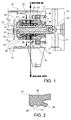
- the pump makes use of three single-action suction and force plungers like the one indicated by the number 11.
- the plunger is sealingly supported and guided in its reciprocating motion by a sealing device 20, which includes a cylindrical sleeve 21 locked by means of a clamping ring 22 coaxially inside a flanged supporting bush 23.
- a closed circuit is formed in the sealing device for a second lubricating fluid (or secondary fluid), in particular lubricating oil, with two ducts, inlet 24 and outlet 25, formed in the inner sleeve and in the bush, and an axially extended annular chamber 26 formed in the internal cylindrical cavity 27 of the sleeve, around the plunger.
- a respective annular oil sealing gasket 28, 29 is provided, fixed to the cylindrical sleeve 21 and acting against the plunger.
- a sealing gasket 32 sealing against the primary fluid, particularly cement; at the opposite end, on the dry side near the clamping ring 22, a scraper ring 33 is mounted.
- gaskets sealing against cement have an average life of 200-300 hours, very variable depending on the type of cement and the operating conditions: pressure, flow rate and SPM (number of strikes per minute).
- pressure pressure
- flow rate number of strikes per minute
- SPM number of strikes per minute
- numeral 10 generally designates a reciprocating pump with suction and force plungers, capable of working at high pressures for injecting concrete mixtures in order to increase mechanical or moisture-proofing characteristics of soils.
- the pump 10 in this example is a reciprocating pump with several cylinders side by side in line, in each of which there runs a respective single-action suction and force plunger 11, only one of which is shown in the drawing.
- the pump consists of a system having three plungers, which define a so-called "Triplex pump".
- the plunger 11 is connected, by means of a connection system 12 (here represented as a collar joint, but as a variant it can also be made using a tie-rod or equivalent components) to a rod 13 driven by a crankshaft (not shown), by a respective connecting rod (not shown).
- the body 14 of the pump is integral with a block 15 in which there are formed pumping chambers 16, one for each plunger.
- the plunger penetrates into the pumping chamber through an aperture 17.
- the pumping chamber 16 reduces its volume as a result of the entry of the plunger 11, resulting in an increase in the pressure of the primary fluid contained therein.
- the valve (not represented) opens an outlet and the pressurized fluid is injected into the pumping line until it reaches the drilling machine.
- the term "primary fluid” or “first fluid” refers to a fluid which is to be pressurized by the pump and injected into a soil.
- the primary fluid will be a mixture containing cement (for example water and cement, or water, cement and bentonite).
- second fluid or “secondary fluid” will indicate in what follows a fluid which is used principally for lubricating the plungers (or the plunger) of the pump, according to procedures known per se.
- the second fluid is made up preferably, but not necessarily, of lubricating oil.
- This third cooling fluid can be, for example, water or an aqueous mixture or solution, suitable for the purposes set forth herein.
- the plunger 11 is sealingly supported and guided, in its reciprocating motion in a direction here defined as “longitudinal”, by a sealing and guiding device designated overall by reference number 20.
- the sealing device 20 comprises a cylindrical sleeve 21 locked by means of a clamping ring 22 arranged coaxially within a flanged supporting bush 23.
- the bush 23 may be removably fastened to the body 14 of the pump.
- the lubrication circuit includes two radial ducts formed in the inner sleeve and in the bush, specifically an oil inlet duct 24, an oil outlet duct 25, and an axially extended annular chamber 26 formed in the inner cylindrical cavity 27 of the sleeve, at the interface with the plunger.
- the inlet and outlet ducts for the secondary fluid may also be inverted.
- two respective annular oil sealing gaskets 28, 29 are arranged, fixed to the cylindrical sleeve 21 and acting against the plunger 11.
- the gasket 28 is oriented with its principal sealing lip extending towards the "wet” side, while the sealing gasket 29 itself also may be advantageously oriented with its principal sealing lip towards the "wet” side. This orientation allows the seal from the lubrication chamber 26 not to be hermetic towards the "wet” side, thus allowing a slow and continuous controlled leakage of lubricating fluid which serves to moisten a sealing gasket 37, described hereinafter, thus keeping it lubricated.
- Two further O-ring gaskets 30, 31 may be interposed between the sleeve 21 and the supporting bush 23, with sealing functions against the secondary lubricating fluid.
- a cooling circuit with a third fluid, such as water (or other liquid) is formed in the sealing device 20, with radial intake duct 34 and outlet duct 35 formed through the outer bush and the inner sleeve 21, and an annular chamber 36 formed in the internal cylindrical cavity 27 of the sleeve around the plunger 11.
- a third fluid such as water (or other liquid)
- the intake and outlet ducts can be inverted with respect to what is shown, without altering the functionality of the system.
- the annular chamber 36 is sealed toward the "wet" side by the first sealing gasket 32 sealing against cement, while on the opposite side, facing towards the clamping ring 22, the chamber 36 is sealed against the plunger 11 by a second guiding and sealing gasket 37 sealing against the primary fluid, particularly against cement mixtures.
- the second sealing gasket 37 is axially interposed between the first sealing gasket 32 sealing against the first fluid and the annular chamber 26 of the lubrication circuit.
- the second cement sealing gasket 37 may be located adjacent to the oil sealing gasket 29.
- the sealing gaskets 28, 29, 32, 37 and the scraper 33 are seated in respective annular grooves formed in the internal cylindrical cavity 27 of sleeve 21.
- the second sealing gasket 37 in addition to sealing against the cooling water, also serves as a guide element for the plunger 11, and therefore its shape and the material from which it is made are chosen appropriately to resist high specific pressures.
- the second sealing gasket 37 can also incorporate the functions of the sealing gasket 29 and therefore the latter can be omitted.
- the sealing gasket 37 directly delimits the annular chamber 26 of the second lubrication fluid, also performing sealing functions against the secondary fluid on the "wet" side as well as those of sealing the primary fluid and guiding the plunger piston 11.
- the plunger 11 moves between an axially retracted position (to the left in figure 1 ) and an axially extended position (to the right) in which it enters deeper into the pumping chamber 16. In every position taken by the plunger 11 along its stroke, at least a part of its cylindrical outer surface is always seated within the inner cylindrical cavity 27 and faces both of the annular chambers 26 and 36.
- the sealing gasket 37 has an annular body 38 from which protrude internally several annular reliefs, in this example three in number, suitable for sliding against the plunger 11.
- a sealing lip 39 of a generally truncated-conical shape, projects obliquely towards the wet axial side of the pump and radially towards the plunger.
- Two annular reliefs 40, 41 axially spaced apart from one another, project in radially internal directions, and preferably each terminate with a respective radially internal cylindrical surface suitable for guiding and stabilizing the plunger 11.
- the sealing lip 39 is located closer to the pumping chamber 16, while the annular reliefs 40, 41 are farther from the pumping chamber.
- the accumulation of lubricant helps to increase the life of the sealing gasket 37.
- the alternation between full and empty also enables dispersal of the heat due to the friction between the internal cylindrical surface of the reliefs 40 and 41, the lip 39 and the outer surface of the plunger 11.
- the annular reliefs 40, 41 have an axial section of trapezium shape.
- the annular reliefs 40, 41 considerably reduce the radial loads and the friction on the first frontal sealing gasket 32, whose principal task remains sealing against cement.
- the plain cylindrical side on reliefs 40 and 41 instead of the normal apex which can be found on profiles with a triangular section, ensures that the plunger 11 is correctly guided.
- the cylindrical inner surface of reliefs 40, 41 can contain furrows or grooves suitable for allowing the passage of secondary fluid for lubricating at least one of the said reliefs and the sealing lip 39.
- the second sealing gasket 37 has also the function to provide a seal against cement.
- the third cooling fluid water or other liquid which circulates in the chamber 36 also serves to lubricate the second sealing gasket 37 and to further cool the plunger, by direct washing.
- This fluid therefore has two functions: the principal function of cooling the seals, the plunger and the sleeve, and the secondary function of lubricating sealing gaskets 32 and 37 which would not be reached by the secondary lubricating fluid. In fact the inner side, toward the "wet" part of sealing gasket 37 and the whole of sealing gasket 32, would not be in contact with the secondary lubricating fluid.
- liquids enriched with additives to improve this second function, or oil (in this case, to offset a disadvantage caused by the contamination of a valuable fluid, there is a further extension of the life of the sealing components and the other parts in relative movement and subject to the presence of abrasive fluids (such as cement mixtures).
- abrasive fluids such as cement mixtures.
- the water in this case, however, unlike conventional pumps, it is possible to detect simply that the water contains a second component, because the outlet allows the fluid to free-fall or into an open container, or pass into a transparent tube close to the operator's station. While lubricating oil requires a closed and filtered circuit, the water can be directed and handled more freely because it does not represent an environmental pollutant.
- the second sealing gasket 37 in the event of damage to the first sealing gasket 32 (which is in direct contact with the cement zone and is therefore the most subject to deterioration), allows the pump to maintain its functionality because, as a secondary function, it acts as a cement seal. In this way the cement is prevented from ending up in the oil lubrication system, which allows it to be isolated and better protected.
- an overload sensor (not shown) in the washing line, downstream of the plunger, it is possible to detect the presence of cement in the cooling circuit, indicating that the first, outermost sealing gasket 32 is in a worn condition.
- This sensor will send a signal to a data processing unit (not shown), which, on processing the information, will display an alarm to the operator, on a control panel in the command area such as a warning light, an acoustic alarm or, if there is a monitor, a pop-up alarm with or without an audio signal.
- the overload sensor may be of pressure type (any inclusion of cement mixture inside the duct for the third fluid will increase the pressure necessary for the contaminated fluid to circulate).
- optical sensors may be used, such as those which measure fluorescence in UV light. Such sensors are able to detect the presence of oil in water. They can therefore warn of a problem with the sealing of the system of lubrication with the secondary fluid. When the concentration of oil, coming from the leakage from sealing gasket 29, in the third fluid is too high, a problem may be indicated with sealing gasket 29.
- This sensor with the others described above can lead to the indication of both problems: a damage to sealing gasket 32 for the primary fluid and/or damage to sealing gasket 29 for the secondary fluid.
- a worn condition of the outer sealing gasket 32 is easily detectable from the presence of cement in the third cooling fluid (or liquid), and that the combination of the cooling circuit with the addition of the second sealing gasket 37 enables a considerable increase in the life of the first outer sealing gasket 32, as it is possible to circumscribe an isolated volume which can contain cooling fluid and lubricant. Having the sealing still guaranteed by the second sealing gasket 37, the operator can decide whether to proceed immediately with replacement or to defer it, without risking damage to the plunger 11, the sleeve 21 or the lubrication circuit, or risking contaminating the lubricating oil.
- the invention results in lower maintenance costs, a prolongation of life for the components (especially for the final sealing gasket sealing against cement, and for the sleeve of the sealing device), and extended and predictable servicing intervals.
- a single servicing intervention for changing the lubricating oil and the gaskets is possible.
- the state of wear of the sealing gaskets sealing against cement can be monitored.
- the gaskets must no longer be replaced only at scheduled and preventive maintenance intervals but can always be replaced promptly as soon as they are found to be in a worn condition. If necessary, if the final cement sealing gasket is moderately worn, it is possible to continue working without risking damaging the sleeve or contaminating the oil, thanks to the second cement sealing gasket.
- the second sealing gasket makes it possible to complete not only the execution of the jet column in progress, but for example to complete all the columns for the day or to reach the weekend, the period specified for ordinary and extraordinary maintenance on site.
- the possibility of continuing working makes it possible to schedule servicing activities without delaying the planned production.
Landscapes
- Engineering & Computer Science (AREA)
- Mechanical Engineering (AREA)
- General Engineering & Computer Science (AREA)
- Details Of Reciprocating Pumps (AREA)
- Reciprocating Pumps (AREA)
Applications Claiming Priority (1)
| Application Number | Priority Date | Filing Date | Title |
|---|---|---|---|
| IT001029A ITTO20111029A1 (it) | 2011-11-08 | 2011-11-08 | Pompa ad alta pressione per iniettare miscele cementizie |
Publications (2)
| Publication Number | Publication Date |
|---|---|
| EP2592268A1 EP2592268A1 (en) | 2013-05-15 |
| EP2592268B1 true EP2592268B1 (en) | 2014-08-13 |
Family
ID=45370687
Family Applications (1)
| Application Number | Title | Priority Date | Filing Date |
|---|---|---|---|
| EP12191404.8A Not-in-force EP2592268B1 (en) | 2011-11-08 | 2012-11-06 | A high pressure pump for injecting cement mixtures |
Country Status (5)
| Country | Link |
|---|---|
| US (1) | US9133834B2 (it) |
| EP (1) | EP2592268B1 (it) |
| KR (1) | KR101993479B1 (it) |
| IT (1) | ITTO20111029A1 (it) |
| SG (1) | SG190518A1 (it) |
Families Citing this family (8)
| Publication number | Priority date | Publication date | Assignee | Title |
|---|---|---|---|---|
| CN103321892B (zh) * | 2013-05-29 | 2016-06-22 | 三一汽车制造有限公司 | 一种弹性活塞、泵送系统及工程机械 |
| AR103757A1 (es) * | 2015-02-23 | 2017-05-31 | Schlumberger Technology Bv | Métodos y sistemas para presurizar fluidos agresivos |
| EP3267035B1 (en) * | 2016-07-07 | 2020-12-09 | Cameron Technologies Limited | Mud pump sealing assembly |
| CN106593858B (zh) * | 2017-01-24 | 2019-08-13 | 宁波合力机泵股份有限公司 | 一种往复泵柱塞填料密封润滑装置 |
| EP3706891B1 (en) | 2017-11-07 | 2022-06-22 | SABIC Global Technologies B.V. | Use of a piston system for forming an elastomer agglomerate composition |
| JP2019173655A (ja) * | 2018-03-28 | 2019-10-10 | 株式会社常光 | プランジャポンプ |
| CN110905758B (zh) * | 2019-12-23 | 2024-12-06 | 江苏盐邦泵业制造有限公司 | 一种耐磨柱塞泥浆泵 |
| CN120212057B (zh) * | 2025-05-27 | 2025-08-26 | 烟台恒邦泵业有限公司 | 一种输送高温物料的旋转喷射泵 |
Family Cites Families (8)
| Publication number | Priority date | Publication date | Assignee | Title |
|---|---|---|---|---|
| US3114326A (en) * | 1961-09-07 | 1963-12-17 | Aldrich Pump Company | Plunger type pump especially for high pressure |
| US3602613A (en) * | 1969-09-25 | 1971-08-31 | Duriron Co | High pressure pump |
| SE8105988L (sv) * | 1981-10-09 | 1983-04-10 | Hk Eng Ab | Pump av deplacementtyp |
| US5209495A (en) * | 1990-09-04 | 1993-05-11 | Palmour Harold H | Reciprocating rod pump seal assembly |
| CA2154875A1 (en) * | 1993-02-02 | 1994-08-18 | Karl Schlecht | Process for conveying thick matter containing preshredded scrap metal or similar solids |
| US6834862B2 (en) * | 2002-01-23 | 2004-12-28 | Mark R. Wilkinson | Shaft sealing system for a rotary mechanical device |
| US7794215B2 (en) * | 2007-02-12 | 2010-09-14 | Regency Technologies Llc | High pressure slurry plunger pump with clean fluid valve arrangement |
| CN101113730B (zh) * | 2007-08-03 | 2010-05-19 | 宝鸡石油机械有限责任公司 | 钻井泵缸套内外表面冷却装置 |
-
2011
- 2011-11-08 IT IT001029A patent/ITTO20111029A1/it unknown
-
2012
- 2012-11-01 SG SG2012080818A patent/SG190518A1/en unknown
- 2012-11-06 EP EP12191404.8A patent/EP2592268B1/en not_active Not-in-force
- 2012-11-06 KR KR1020120124908A patent/KR101993479B1/ko not_active Expired - Fee Related
- 2012-11-08 US US13/671,571 patent/US9133834B2/en not_active Expired - Fee Related
Also Published As
| Publication number | Publication date |
|---|---|
| US20130115115A1 (en) | 2013-05-09 |
| SG190518A1 (en) | 2013-06-28 |
| KR101993479B1 (ko) | 2019-06-26 |
| ITTO20111029A1 (it) | 2013-05-09 |
| KR20130050889A (ko) | 2013-05-16 |
| EP2592268A1 (en) | 2013-05-15 |
| US9133834B2 (en) | 2015-09-15 |
Similar Documents
| Publication | Publication Date | Title |
|---|---|---|
| EP2592268B1 (en) | A high pressure pump for injecting cement mixtures | |
| FI121139B (fi) | Hydraulivasara ja työkaluholkki | |
| US20080272554A1 (en) | System for backup rod seal for hydraulic cylinder | |
| JP2008511794A (ja) | 低摩擦往復ポンプ | |
| CN102278479A (zh) | Y型密封单元 | |
| US10054226B1 (en) | Mechanical sealing system | |
| CN104165171A (zh) | 一种传感器保护装置、油缸及工程机械 | |
| CA1134876A (en) | Seal arrangement for hydraulic pump | |
| US10436275B2 (en) | Gas strut | |
| CN216077787U (zh) | 一种防渗漏油缸 | |
| US20180355973A1 (en) | Leak resistant pump | |
| US3926095A (en) | Piston pump | |
| CN103452953A (zh) | 液压油缸及其防水系统以及混凝土泵送设备 | |
| JP5767990B2 (ja) | 流体圧シリンダ | |
| US4514148A (en) | Hydraulically actuated pump | |
| US12215723B2 (en) | Fluid pressure cylinder | |
| JP5147581B2 (ja) | 往復動ポンプ | |
| RU158391U1 (ru) | Механическое уплотнение | |
| RU108534U1 (ru) | Механическое уплотнение деталей с наружной цилиндрической поверхностью | |
| KR101237593B1 (ko) | 가변형 배출벤트를 갖는 단동식 공압실린더 | |
| KR20200015569A (ko) | 냉각 및 윤활 밀봉부를 수용하기 위한 밸브를 가진 유압식 피스톤 | |
| IT201800006145A1 (it) | Pompa volumetrica a pistoni | |
| CN223594597U (zh) | 一种油缸密封系统 | |
| KR20100114562A (ko) | 오리피스 필터를 구비한 유압실린더 쿠션장치 | |
| WO2010131976A1 (en) | Pump piston device |
Legal Events
| Date | Code | Title | Description |
|---|---|---|---|
| PUAI | Public reference made under article 153(3) epc to a published international application that has entered the european phase |
Free format text: ORIGINAL CODE: 0009012 |
|
| AK | Designated contracting states |
Kind code of ref document: A1 Designated state(s): AL AT BE BG CH CY CZ DE DK EE ES FI FR GB GR HR HU IE IS IT LI LT LU LV MC MK MT NL NO PL PT RO RS SE SI SK SM TR |
|
| AX | Request for extension of the european patent |
Extension state: BA ME |
|
| 17P | Request for examination filed |
Effective date: 20131107 |
|
| RBV | Designated contracting states (corrected) |
Designated state(s): AL AT BE BG CH CY CZ DE DK EE ES FI FR GB GR HR HU IE IS IT LI LT LU LV MC MK MT NL NO PL PT RO RS SE SI SK SM TR |
|
| RIC1 | Information provided on ipc code assigned before grant |
Ipc: F04B 53/02 20060101ALI20131129BHEP Ipc: F04B 53/08 20060101ALI20131129BHEP Ipc: F04B 15/02 20060101AFI20131129BHEP Ipc: F04B 53/18 20060101ALI20131129BHEP |
|
| GRAP | Despatch of communication of intention to grant a patent |
Free format text: ORIGINAL CODE: EPIDOSNIGR1 |
|
| INTG | Intention to grant announced |
Effective date: 20140124 |
|
| GRAS | Grant fee paid |
Free format text: ORIGINAL CODE: EPIDOSNIGR3 |
|
| GRAA | (expected) grant |
Free format text: ORIGINAL CODE: 0009210 |
|
| RAP1 | Party data changed (applicant data changed or rights of an application transferred) |
Owner name: SOILMEC S.P.A. |
|
| AK | Designated contracting states |
Kind code of ref document: B1 Designated state(s): AL AT BE BG CH CY CZ DE DK EE ES FI FR GB GR HR HU IE IS IT LI LT LU LV MC MK MT NL NO PL PT RO RS SE SI SK SM TR |
|
| REG | Reference to a national code |
Ref country code: GB Ref legal event code: FG4D |
|
| REG | Reference to a national code |
Ref country code: CH Ref legal event code: EP Ref country code: AT Ref legal event code: REF Ref document number: 682420 Country of ref document: AT Kind code of ref document: T Effective date: 20140815 |
|
| REG | Reference to a national code |
Ref country code: IE Ref legal event code: FG4D |
|
| REG | Reference to a national code |
Ref country code: DE Ref legal event code: R096 Ref document number: 602012002734 Country of ref document: DE Effective date: 20140925 |
|
| REG | Reference to a national code |
Ref country code: NL Ref legal event code: VDEP Effective date: 20140813 |
|
| REG | Reference to a national code |
Ref country code: AT Ref legal event code: MK05 Ref document number: 682420 Country of ref document: AT Kind code of ref document: T Effective date: 20140813 |
|
| REG | Reference to a national code |
Ref country code: LT Ref legal event code: MG4D |
|
| PG25 | Lapsed in a contracting state [announced via postgrant information from national office to epo] |
Ref country code: GR Free format text: LAPSE BECAUSE OF FAILURE TO SUBMIT A TRANSLATION OF THE DESCRIPTION OR TO PAY THE FEE WITHIN THE PRESCRIBED TIME-LIMIT Effective date: 20141114 Ref country code: ES Free format text: LAPSE BECAUSE OF FAILURE TO SUBMIT A TRANSLATION OF THE DESCRIPTION OR TO PAY THE FEE WITHIN THE PRESCRIBED TIME-LIMIT Effective date: 20140813 Ref country code: SE Free format text: LAPSE BECAUSE OF FAILURE TO SUBMIT A TRANSLATION OF THE DESCRIPTION OR TO PAY THE FEE WITHIN THE PRESCRIBED TIME-LIMIT Effective date: 20140813 Ref country code: FI Free format text: LAPSE BECAUSE OF FAILURE TO SUBMIT A TRANSLATION OF THE DESCRIPTION OR TO PAY THE FEE WITHIN THE PRESCRIBED TIME-LIMIT Effective date: 20140813 Ref country code: PT Free format text: LAPSE BECAUSE OF FAILURE TO SUBMIT A TRANSLATION OF THE DESCRIPTION OR TO PAY THE FEE WITHIN THE PRESCRIBED TIME-LIMIT Effective date: 20141215 Ref country code: LT Free format text: LAPSE BECAUSE OF FAILURE TO SUBMIT A TRANSLATION OF THE DESCRIPTION OR TO PAY THE FEE WITHIN THE PRESCRIBED TIME-LIMIT Effective date: 20140813 Ref country code: NO Free format text: LAPSE BECAUSE OF FAILURE TO SUBMIT A TRANSLATION OF THE DESCRIPTION OR TO PAY THE FEE WITHIN THE PRESCRIBED TIME-LIMIT Effective date: 20141113 Ref country code: BG Free format text: LAPSE BECAUSE OF FAILURE TO SUBMIT A TRANSLATION OF THE DESCRIPTION OR TO PAY THE FEE WITHIN THE PRESCRIBED TIME-LIMIT Effective date: 20141113 |
|
| PG25 | Lapsed in a contracting state [announced via postgrant information from national office to epo] |
Ref country code: HR Free format text: LAPSE BECAUSE OF FAILURE TO SUBMIT A TRANSLATION OF THE DESCRIPTION OR TO PAY THE FEE WITHIN THE PRESCRIBED TIME-LIMIT Effective date: 20140813 Ref country code: LV Free format text: LAPSE BECAUSE OF FAILURE TO SUBMIT A TRANSLATION OF THE DESCRIPTION OR TO PAY THE FEE WITHIN THE PRESCRIBED TIME-LIMIT Effective date: 20140813 Ref country code: RS Free format text: LAPSE BECAUSE OF FAILURE TO SUBMIT A TRANSLATION OF THE DESCRIPTION OR TO PAY THE FEE WITHIN THE PRESCRIBED TIME-LIMIT Effective date: 20140813 Ref country code: IS Free format text: LAPSE BECAUSE OF FAILURE TO SUBMIT A TRANSLATION OF THE DESCRIPTION OR TO PAY THE FEE WITHIN THE PRESCRIBED TIME-LIMIT Effective date: 20141213 Ref country code: CY Free format text: LAPSE BECAUSE OF FAILURE TO SUBMIT A TRANSLATION OF THE DESCRIPTION OR TO PAY THE FEE WITHIN THE PRESCRIBED TIME-LIMIT Effective date: 20140813 Ref country code: AT Free format text: LAPSE BECAUSE OF FAILURE TO SUBMIT A TRANSLATION OF THE DESCRIPTION OR TO PAY THE FEE WITHIN THE PRESCRIBED TIME-LIMIT Effective date: 20140813 |
|
| PG25 | Lapsed in a contracting state [announced via postgrant information from national office to epo] |
Ref country code: NL Free format text: LAPSE BECAUSE OF FAILURE TO SUBMIT A TRANSLATION OF THE DESCRIPTION OR TO PAY THE FEE WITHIN THE PRESCRIBED TIME-LIMIT Effective date: 20140813 |
|
| PG25 | Lapsed in a contracting state [announced via postgrant information from national office to epo] |
Ref country code: DK Free format text: LAPSE BECAUSE OF FAILURE TO SUBMIT A TRANSLATION OF THE DESCRIPTION OR TO PAY THE FEE WITHIN THE PRESCRIBED TIME-LIMIT Effective date: 20140813 Ref country code: CZ Free format text: LAPSE BECAUSE OF FAILURE TO SUBMIT A TRANSLATION OF THE DESCRIPTION OR TO PAY THE FEE WITHIN THE PRESCRIBED TIME-LIMIT Effective date: 20140813 Ref country code: EE Free format text: LAPSE BECAUSE OF FAILURE TO SUBMIT A TRANSLATION OF THE DESCRIPTION OR TO PAY THE FEE WITHIN THE PRESCRIBED TIME-LIMIT Effective date: 20140813 Ref country code: SK Free format text: LAPSE BECAUSE OF FAILURE TO SUBMIT A TRANSLATION OF THE DESCRIPTION OR TO PAY THE FEE WITHIN THE PRESCRIBED TIME-LIMIT Effective date: 20140813 Ref country code: RO Free format text: LAPSE BECAUSE OF FAILURE TO SUBMIT A TRANSLATION OF THE DESCRIPTION OR TO PAY THE FEE WITHIN THE PRESCRIBED TIME-LIMIT Effective date: 20140813 |
|
| REG | Reference to a national code |
Ref country code: DE Ref legal event code: R097 Ref document number: 602012002734 Country of ref document: DE |
|
| PG25 | Lapsed in a contracting state [announced via postgrant information from national office to epo] |
Ref country code: PL Free format text: LAPSE BECAUSE OF FAILURE TO SUBMIT A TRANSLATION OF THE DESCRIPTION OR TO PAY THE FEE WITHIN THE PRESCRIBED TIME-LIMIT Effective date: 20140813 |
|
| PLBE | No opposition filed within time limit |
Free format text: ORIGINAL CODE: 0009261 |
|
| STAA | Information on the status of an ep patent application or granted ep patent |
Free format text: STATUS: NO OPPOSITION FILED WITHIN TIME LIMIT |
|
| PG25 | Lapsed in a contracting state [announced via postgrant information from national office to epo] |
Ref country code: LU Free format text: LAPSE BECAUSE OF FAILURE TO SUBMIT A TRANSLATION OF THE DESCRIPTION OR TO PAY THE FEE WITHIN THE PRESCRIBED TIME-LIMIT Effective date: 20141106 Ref country code: BE Free format text: LAPSE BECAUSE OF NON-PAYMENT OF DUE FEES Effective date: 20141130 Ref country code: MC Free format text: LAPSE BECAUSE OF FAILURE TO SUBMIT A TRANSLATION OF THE DESCRIPTION OR TO PAY THE FEE WITHIN THE PRESCRIBED TIME-LIMIT Effective date: 20140813 |
|
| 26N | No opposition filed |
Effective date: 20150515 |
|
| REG | Reference to a national code |
Ref country code: IE Ref legal event code: MM4A |
|
| PG25 | Lapsed in a contracting state [announced via postgrant information from national office to epo] |
Ref country code: IE Free format text: LAPSE BECAUSE OF NON-PAYMENT OF DUE FEES Effective date: 20141106 |
|
| PG25 | Lapsed in a contracting state [announced via postgrant information from national office to epo] |
Ref country code: SI Free format text: LAPSE BECAUSE OF FAILURE TO SUBMIT A TRANSLATION OF THE DESCRIPTION OR TO PAY THE FEE WITHIN THE PRESCRIBED TIME-LIMIT Effective date: 20140813 |
|
| REG | Reference to a national code |
Ref country code: FR Ref legal event code: PLFP Year of fee payment: 4 |
|
| REG | Reference to a national code |
Ref country code: CH Ref legal event code: PL |
|
| PG25 | Lapsed in a contracting state [announced via postgrant information from national office to epo] |
Ref country code: CH Free format text: LAPSE BECAUSE OF NON-PAYMENT OF DUE FEES Effective date: 20151130 Ref country code: LI Free format text: LAPSE BECAUSE OF NON-PAYMENT OF DUE FEES Effective date: 20151130 Ref country code: MT Free format text: LAPSE BECAUSE OF FAILURE TO SUBMIT A TRANSLATION OF THE DESCRIPTION OR TO PAY THE FEE WITHIN THE PRESCRIBED TIME-LIMIT Effective date: 20140813 Ref country code: HU Free format text: LAPSE BECAUSE OF FAILURE TO SUBMIT A TRANSLATION OF THE DESCRIPTION OR TO PAY THE FEE WITHIN THE PRESCRIBED TIME-LIMIT; INVALID AB INITIO Effective date: 20121106 Ref country code: BE Free format text: LAPSE BECAUSE OF FAILURE TO SUBMIT A TRANSLATION OF THE DESCRIPTION OR TO PAY THE FEE WITHIN THE PRESCRIBED TIME-LIMIT Effective date: 20140813 |
|
| REG | Reference to a national code |
Ref country code: FR Ref legal event code: PLFP Year of fee payment: 5 |
|
| PG25 | Lapsed in a contracting state [announced via postgrant information from national office to epo] |
Ref country code: SM Free format text: LAPSE BECAUSE OF FAILURE TO SUBMIT A TRANSLATION OF THE DESCRIPTION OR TO PAY THE FEE WITHIN THE PRESCRIBED TIME-LIMIT Effective date: 20140813 |
|
| GBPC | Gb: european patent ceased through non-payment of renewal fee |
Effective date: 20161106 |
|
| PG25 | Lapsed in a contracting state [announced via postgrant information from national office to epo] |
Ref country code: GB Free format text: LAPSE BECAUSE OF NON-PAYMENT OF DUE FEES Effective date: 20161106 |
|
| REG | Reference to a national code |
Ref country code: FR Ref legal event code: PLFP Year of fee payment: 6 |
|
| PG25 | Lapsed in a contracting state [announced via postgrant information from national office to epo] |
Ref country code: MK Free format text: LAPSE BECAUSE OF FAILURE TO SUBMIT A TRANSLATION OF THE DESCRIPTION OR TO PAY THE FEE WITHIN THE PRESCRIBED TIME-LIMIT Effective date: 20140813 |
|
| PG25 | Lapsed in a contracting state [announced via postgrant information from national office to epo] |
Ref country code: AL Free format text: LAPSE BECAUSE OF FAILURE TO SUBMIT A TRANSLATION OF THE DESCRIPTION OR TO PAY THE FEE WITHIN THE PRESCRIBED TIME-LIMIT Effective date: 20140813 |
|
| PGFP | Annual fee paid to national office [announced via postgrant information from national office to epo] |
Ref country code: TR Payment date: 20201030 Year of fee payment: 9 |
|
| PGFP | Annual fee paid to national office [announced via postgrant information from national office to epo] |
Ref country code: IT Payment date: 20221026 Year of fee payment: 11 Ref country code: FR Payment date: 20221122 Year of fee payment: 11 Ref country code: DE Payment date: 20221123 Year of fee payment: 11 |
|
| REG | Reference to a national code |
Ref country code: DE Ref legal event code: R119 Ref document number: 602012002734 Country of ref document: DE |
|
| PG25 | Lapsed in a contracting state [announced via postgrant information from national office to epo] |
Ref country code: TR Free format text: LAPSE BECAUSE OF NON-PAYMENT OF DUE FEES Effective date: 20211106 |
|
| PG25 | Lapsed in a contracting state [announced via postgrant information from national office to epo] |
Ref country code: DE Free format text: LAPSE BECAUSE OF NON-PAYMENT OF DUE FEES Effective date: 20240601 |
|
| PG25 | Lapsed in a contracting state [announced via postgrant information from national office to epo] |
Ref country code: FR Free format text: LAPSE BECAUSE OF NON-PAYMENT OF DUE FEES Effective date: 20231130 |
|
| PG25 | Lapsed in a contracting state [announced via postgrant information from national office to epo] |
Ref country code: FR Free format text: LAPSE BECAUSE OF NON-PAYMENT OF DUE FEES Effective date: 20231130 Ref country code: DE Free format text: LAPSE BECAUSE OF NON-PAYMENT OF DUE FEES Effective date: 20240601 |
|
| PG25 | Lapsed in a contracting state [announced via postgrant information from national office to epo] |
Ref country code: IT Free format text: LAPSE BECAUSE OF NON-PAYMENT OF DUE FEES Effective date: 20231106 |
|
| PG25 | Lapsed in a contracting state [announced via postgrant information from national office to epo] |
Ref country code: IT Free format text: LAPSE BECAUSE OF NON-PAYMENT OF DUE FEES Effective date: 20231106 |