EP2592252A2 - Gearbox deoiler with pre-pressuring component - Google Patents
Gearbox deoiler with pre-pressuring component Download PDFInfo
- Publication number
- EP2592252A2 EP2592252A2 EP20120191897 EP12191897A EP2592252A2 EP 2592252 A2 EP2592252 A2 EP 2592252A2 EP 20120191897 EP20120191897 EP 20120191897 EP 12191897 A EP12191897 A EP 12191897A EP 2592252 A2 EP2592252 A2 EP 2592252A2
- Authority
- EP
- European Patent Office
- Prior art keywords
- mixture
- air
- gearbox
- shaft
- oil
- Prior art date
- Legal status (The legal status is an assumption and is not a legal conclusion. Google has not performed a legal analysis and makes no representation as to the accuracy of the status listed.)
- Granted
Links
- 239000000203 mixture Substances 0.000 claims abstract description 53
- 238000000034 method Methods 0.000 claims description 8
- 239000003921 oil Substances 0.000 description 41
- 239000012530 fluid Substances 0.000 description 5
- 230000001133 acceleration Effects 0.000 description 4
- 230000003993 interaction Effects 0.000 description 2
- 230000004075 alteration Effects 0.000 description 1
- 238000007664 blowing Methods 0.000 description 1
- 238000004891 communication Methods 0.000 description 1
- 239000006260 foam Substances 0.000 description 1
- 239000000446 fuel Substances 0.000 description 1
- 239000007788 liquid Substances 0.000 description 1
- 239000010687 lubricating oil Substances 0.000 description 1
- 239000002184 metal Substances 0.000 description 1
- 239000002245 particle Substances 0.000 description 1
- 238000000926 separation method Methods 0.000 description 1
- 238000006467 substitution reaction Methods 0.000 description 1
Images


Classifications
-
- F—MECHANICAL ENGINEERING; LIGHTING; HEATING; WEAPONS; BLASTING
- F02—COMBUSTION ENGINES; HOT-GAS OR COMBUSTION-PRODUCT ENGINE PLANTS
- F02C—GAS-TURBINE PLANTS; AIR INTAKES FOR JET-PROPULSION PLANTS; CONTROLLING FUEL SUPPLY IN AIR-BREATHING JET-PROPULSION PLANTS
- F02C7/00—Features, components parts, details or accessories, not provided for in, or of interest apart form groups F02C1/00 - F02C6/00; Air intakes for jet-propulsion plants
- F02C7/32—Arrangement, mounting, or driving, of auxiliaries
-
- F—MECHANICAL ENGINEERING; LIGHTING; HEATING; WEAPONS; BLASTING
- F01—MACHINES OR ENGINES IN GENERAL; ENGINE PLANTS IN GENERAL; STEAM ENGINES
- F01D—NON-POSITIVE DISPLACEMENT MACHINES OR ENGINES, e.g. STEAM TURBINES
- F01D25/00—Component parts, details, or accessories, not provided for in, or of interest apart from, other groups
- F01D25/18—Lubricating arrangements
-
- F—MECHANICAL ENGINEERING; LIGHTING; HEATING; WEAPONS; BLASTING
- F02—COMBUSTION ENGINES; HOT-GAS OR COMBUSTION-PRODUCT ENGINE PLANTS
- F02C—GAS-TURBINE PLANTS; AIR INTAKES FOR JET-PROPULSION PLANTS; CONTROLLING FUEL SUPPLY IN AIR-BREATHING JET-PROPULSION PLANTS
- F02C6/00—Plural gas-turbine plants; Combinations of gas-turbine plants with other apparatus; Adaptations of gas-turbine plants for special use
-
- B—PERFORMING OPERATIONS; TRANSPORTING
- B01—PHYSICAL OR CHEMICAL PROCESSES OR APPARATUS IN GENERAL
- B01D—SEPARATION
- B01D45/00—Separating dispersed particles from gases or vapours by gravity, inertia, or centrifugal forces
- B01D45/12—Separating dispersed particles from gases or vapours by gravity, inertia, or centrifugal forces by centrifugal forces
- B01D45/14—Separating dispersed particles from gases or vapours by gravity, inertia, or centrifugal forces by centrifugal forces generated by rotating vanes, discs, drums or brushes
-
- F—MECHANICAL ENGINEERING; LIGHTING; HEATING; WEAPONS; BLASTING
- F01—MACHINES OR ENGINES IN GENERAL; ENGINE PLANTS IN GENERAL; STEAM ENGINES
- F01M—LUBRICATING OF MACHINES OR ENGINES IN GENERAL; LUBRICATING INTERNAL COMBUSTION ENGINES; CRANKCASE VENTILATING
- F01M13/00—Crankcase ventilating or breathing
- F01M13/04—Crankcase ventilating or breathing having means for purifying air before leaving crankcase, e.g. removing oil
- F01M2013/0422—Separating oil and gas with a centrifuge device
-
- F—MECHANICAL ENGINEERING; LIGHTING; HEATING; WEAPONS; BLASTING
- F05—INDEXING SCHEMES RELATING TO ENGINES OR PUMPS IN VARIOUS SUBCLASSES OF CLASSES F01-F04
- F05D—INDEXING SCHEME FOR ASPECTS RELATING TO NON-POSITIVE-DISPLACEMENT MACHINES OR ENGINES, GAS-TURBINES OR JET-PROPULSION PLANTS
- F05D2260/00—Function
- F05D2260/60—Fluid transfer
- F05D2260/609—Deoiling or demisting
-
- Y—GENERAL TAGGING OF NEW TECHNOLOGICAL DEVELOPMENTS; GENERAL TAGGING OF CROSS-SECTIONAL TECHNOLOGIES SPANNING OVER SEVERAL SECTIONS OF THE IPC; TECHNICAL SUBJECTS COVERED BY FORMER USPC CROSS-REFERENCE ART COLLECTIONS [XRACs] AND DIGESTS
- Y10—TECHNICAL SUBJECTS COVERED BY FORMER USPC
- Y10T—TECHNICAL SUBJECTS COVERED BY FORMER US CLASSIFICATION
- Y10T74/00—Machine element or mechanism
- Y10T74/19—Gearing
- Y10T74/19991—Lubrication
Definitions
- the present invention relates to gearboxes, and, in particular, to a deoiler portion of a gearbox.
- a typical gas turbine engine for an aircraft is coupled to a shaft that drives other shafts via a connection to a gearbox.
- a gearbox housing As the air flows through the gearbox housing, a certain amount of oil naturally becomes entrained in the air. For instance, bearing compartments in the turbine can be vented into the gearbox and increase the amount of oil in the air in the gearbox. For a number of reasons, it is desirable that this oil be separated from the air before the air is vented from the gearbox.
- a deoiler In order to separate the oil from the air, a deoiler is included in the gearbox.
- the deoiler includes a separator unit that utilizes centrifugal forces to separate the heavier oil from the lighter air.
- the deoiler includes a shaft to which the separator unit is attached and that includes an outlet through which clean air can be exhausted to the environment.
- a gearbox that includes an inlet configured to receive a mixture of air and oil from an external source and a deoiler.
- the deoiler in this embodiment includes a shaft including an inlet passage and an outlet passage, both formed on an inner portion of the shaft and separated from one another, a separator unit coupled to and surrounding a portion of the shaft and including an inlet and an outlet and a pre-pressuring component coupled to the shaft that increases the pressure of the mixture of oil and air to form a pressurized mixture and provides the pressurized mixture to the inlet of the separator unit.
- a method for removing oil from a mixture of air and oil includes: passing the mixture through a pre-pressuring component to raise the pressure of the mixture of air and oil from a first pressure level to a second pressure level higher than the first level; and providing the mixture of air and oil at the second pressure level to a rotating separator unit coupled to a shaft to remove some or all of the oil from the mixture to create exhaust air.
- FIG. 1 is a cut-away side view of an engine coupled to a gear box
- FIG. 2 is a partial cross sectional top-view of a gearbox
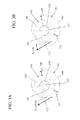
- FIGs. 3A and 3B are cross-sections of a blade assembly surrounded by an outer housing according to two embodiments.
- a simplified turbine 10 is illustrated coupled to a gear box 12.
- the turbine 10 causes air to generally travel in the direction shown by arrow A to generate thrust.
- the turbine 10 includes a fan 11 that draws air into the turbine 10.
- the air is then compressed, in series, by low 14 and high pressure 16 compressors.
- the compressed air is then mixed with fuel and burned in a combustor 18 to create a hot-gas flow that expands in a high pressure turbine 20 and causes the spool 22 to rotate.
- the spool 22 provides rotational force to the high pressure compressor 16.
- the hot-gas flow also drives a low pressure turbine 24 in order to rotate a central shaft 26 and provide rotation energy to, for example, the fan 11 and the low pressure compressor 14.
- the turbine 10 illustrated in FIG. 1 is presented by way of example and the teachings herein can be applied to a gearbox attached to any type of engine or to any other source of rotational energy.
- the central shaft 26 and/or the spool 22 can be coupled to one or more bearing compartments 30 as is known in the art. Pressurized air (indicated by arrows B) from the turbine 10 can enter the bearing compartments 30 and cause oil contained therein to be expelled into the gearbox 12. To that end, one or more air/fluid passages 34 can couple the bearing compartments 30 to the gearbox 12.
- the gearbox 12 could also include a shaft (not shown) linked to the spool 22 or the central shaft 26 that provides rotational energy to the gearbox 12. This rotational energy can be used, for example, to drive a deoiler 40 included in the gearbox 12. In general, the deoiler 40 causes oil entrained in air in the gearbox 12 to be removed from the air as it is expelled from the gearbox 12 as indicated by arrow C.
- FIG. 2 is a partial cross sectional top-view of a gearbox 12 according to one embodiment.
- the gearbox 12 includes a shell 50 that forms the outer boundaries of the gearbox 12.
- the shell 50 includes an inlet 52 through which an air-oil mixture 54 can enter.
- the air-oil mixture 54 can be received, for example, from the bearing compartments 30 via air/fluid passages 34 as shown in FIG. 1 .
- the air-oil mixture 54 could be received from any location and is not limited to being initiated in the bearing compartments 30.
- a mixture of air and oil can be created simply with oil found in the gearbox 12.
- mixture 54 is referred to as an air-oil mixture, it could be a mixture of air and any type of fluid.
- the inlet 52 receives mixture 54 directly from an external pipe directly coupled to the bearing compartment 30.
- the gearbox 12 can include a deoiler 40 that removes some or all of the oil from the air-oil mixture 54 and expels clean air as indicated by arrow C which may be exhausted to atmosphere. While not illustrated, it shall be understood that the gearbox 12 is linked to the turbine 10 and receives rotational energy from it. The rotational energy can be used to drive the deoiler 40.
- the deoiler 40 includes a shaft 41 that is driven by the rotational energy.
- the shaft 41 includes an outlet passage 42 formed on an interior portion thereof through which clean air (arrow C) is exhausted.
- a separator unit 58 is coupled to the shaft 41 and provides a path from a location within the gearbox 12 to the outlet passage 42.
- the separator unit 58 can include a separator media 60 disposed therein such as a metal or other foam.
- the air-oil mixture 54 and any other air/fluid mixture within the shell 50 of the gearbox 12 is drawn into the inlets ports 56 of the separator unit 58 of the deoiler 40.
- the air so drawn shall be referred to herein as inlet flow 64.
- the separator media 60 provides surfaces for oil particles in the inlet flow 64 to adhere to.
- the droplets of oil coalesce and the liquid is centrifugally slung to the outer diameter 66 of the separator unit 58 where it passes through drain holes 70 back into the gearbox 12 as is indicated by arrows 72.
- Air passes from an outside portion of the shaft 41 to the outlet passage 42 through one or more inner passages 43 surrounded by at least a portion of the separator unit 58.
- the pressure drop from the inside of the gearbox 12 to the outlet passage 42 depends upon the flow geometry and the rotational speed of the separator unit 58.
- the geometry factors that influence pressure drop are ones that minimize the flow velocity (large flow area) and that allow gradual changes in flow direction and flow passage area. This avoids turbulence in the flow passages.
- To reduce the geometry related pressure drop usually means the separator unit 58 is made larger and heavier.
- the speed related pressure drop depends upon two things: the centrifugal pressure drop required to move air radially inward to the outlet passage 42 (arrows 80) in opposition to the centrifugal acceleration experienced by the oil.
- the second part of the pressure drop depends upon the flow loss associated with accelerating the inlet flow 64 up to the rotational speed of the separator unit 58.
- this second part of the pressure drop (e.g., flow loss) is usually larger than the centrifugal pressure drop.
- it may be advantageous to minimize the over-all system pressure drop by matching the rotational speed of the inlet flow 64 to the rotational speed of the separator unit 58. By “synchronizing" these speeds, the pressure drop across the separator unit 58 can be reduced.
- the separator unit 58 is stationary. In such a case, little to no acceleration (i.e., pressure) is required for the inlet flow 64 to enter the separator unit 58.
- the separator unit 58 is rotating and the inlet flow 64 is rotationally stationary. In such a case, the inlet flow 64 must accelerate to match the rotational speed of the separator unit 58. The energy for this acceleration comes from the pressure in the inlet flow and so the pressure of the flow inside the separator unit 58 falls a bit. This increases the pressure drop across the separator unit 58. Such a pressure drop is typically overcome by increasing the size of the separator unit 58.
- the inlet flow 64 is rotating about the shaft 41 at or about the same speed as the separator unit 58 is rotating. In this case, no additional energy (e.g., pressure) is required.
- the pressure of the inlet flow 64 can be matched to that required so that it can pass through the separator unit 58 by a pre-pressurizing component 90.
- the pre-pressuring component 90 draws an air-oil mixture 92 that exists in an internal portion 94 of the gearbox 12 and increases the pressure thereof such that its output (inlet flow 64) is at or near the pressure required to force the inlet flow 64 through the separator unit 58 in the manner described above.
- This increase in pressure allows for the situation described above in the second case to be overcome without increasing the size of the separator unit 58 or increasing pressure in the internal portion.
- the pre-pressuring component 90 imparts rotational motion to the inlet flow 64 to make it match or become closer to matching the rotational speed of the separator unit 58. That is, the pre-pressuring component 90 can be utilized to approximate the third case described above.
- the pre-pressuring component 90 is coupled to the shaft 41.
- the shaft 41 includes a shaft inlet 96 through which an air-oil mixture 92 can enter an inlet passage 97 formed within the shaft 41.
- the shaft inlet 96 is separated from and not in fluid communication with the outlet passage 42.
- the shaft inlet 96 is disposed at one end of the shaft 41 and the outlet passage 42 is disposed at the opposite end of the shaft 41.
- the pre-pressuring component 90 includes an outer housing 100.
- the outer housing 100 can have, in one embodiment and as illustrated in FIG. 2 , a cross section that forms a volute or scroll.
- the outer housing 100 could take on other cross-sectional shapes.
- the outer housing 100 could have a substantially circular cross-section.
- the outer housing 100 surrounds a blade assembly 102 that rotates within it and is coupled to the shaft 41.
- the blade assembly 102 includes one or more blades 103.
- the blade assembly 102 includes inlets 104 that allow the air-oil mixture 92 to be drawn from the inlet passage 97 into the outer housing 100 due to rotation of the blade assembly 102 as indicated by arrow 106.
- the blades 103 interact with the air-oil mixture 92. This interaction causes the air-oil mixture 92 to be accelerated towards an outer perimeter 110 of the outer housing 100. This acceleration causes the pressure of the air-oil mixture 92 to increase.
- the air-oil mixture with increased pressure is indicated by arrow 112.
- the pressure of the air-oil mixture 112 is at or near the pressure drop through the separator unit 58.
- the outer housing 100 can also include a connection passage 120 that provides air-oil mixture 112 to inlet ports 56 such that it becomes inlet flow 64.
- inlet flow 64 can be at a pressure that allows it to pass through the separator unit 58 without having to increase the pressure in the internal portion 94.
- the direction of arrow 112 is the same or similar direction to the direction of rotation of the separator unit 58. As such, the amount of pressure that needs to be added to the air-oil mixture 92 to form air-oil mixture 112 can be minimized.
- FIGs. 3A and 3B illustrate two different embodiments of a cross-section of the outer housing 100 and blade assembly 102 shown in FIG. 2 .
- the blade assembly 102 rotates in a clockwise direction as indicated by arrow 138.
- the blade assembly 102 includes a plurality of radially extending blades 103.
- the blades 103 can take on different shapes. For instance, in FIG. 3A the blades 103 are curved and in FIG. 3B they are straight. In one embodiment, the blades 103 are supported on a base 140. Of course, the blades could be coupled solely to an internal diameter 137 of the blade assembly 102 in one embodiment.
- the air-oil mixture 92 enters through inlets 104 ( FIG. 2 ) at the internal diameter 137 of the blade assembly 102.
- the mixture is then flung outwardly due to centrifugal force towards the outer wall 110 of the outer housing 100.
- the distance between the blades 103 or an outer edge of the base 140 and the outer wall 110 increases when measured from a starting location 156 to another location displaced clockwise from the starting location 156. This is illustrated by distances 150 and 152 where distance 152 is greater than and further from location 156 than distance 150.
- the mixture is pressurized due to interactions with the blades 103 and exits the outer housing 100 and is delivered to the connection passage 120 and, ultimately, to the separator 58 ( FIG. 2 ).
Landscapes
- Engineering & Computer Science (AREA)
- Mechanical Engineering (AREA)
- General Engineering & Computer Science (AREA)
- Chemical & Material Sciences (AREA)
- Combustion & Propulsion (AREA)
- Lubrication Details And Ventilation Of Internal Combustion Engines (AREA)
- Control Of Turbines (AREA)
- General Details Of Gearings (AREA)
- Fluid-Pressure Circuits (AREA)
Abstract
Description
- The present invention relates to gearboxes, and, in particular, to a deoiler portion of a gearbox.
- A typical gas turbine engine for an aircraft is coupled to a shaft that drives other shafts via a connection to a gearbox. As the air flows through the gearbox housing, a certain amount of oil naturally becomes entrained in the air. For instance, bearing compartments in the turbine can be vented into the gearbox and increase the amount of oil in the air in the gearbox. For a number of reasons, it is desirable that this oil be separated from the air before the air is vented from the gearbox.
- In order to separate the oil from the air, a deoiler is included in the gearbox. In general, the deoiler includes a separator unit that utilizes centrifugal forces to separate the heavier oil from the lighter air. In some cases, the deoiler includes a shaft to which the separator unit is attached and that includes an outlet through which clean air can be exhausted to the environment.
- When the engine is driving components in the gearbox (e.g., the deoiler), pressures greater than atmospheric build up within the gearbox and, due to the high speed rotating gears within the gearbox, oil from the gearbox itself can become entrained in the air in chamber. As mentioned above, oil can also be introduced from the bearing compartments due to air that leaks into the bearing compartments from the higher-pressure sections of the engine (e.g., compressors and turbines). It is often desirable to minimize the pressure in the gearbox and bearing compartments to help balance the pressure forces on the seals to avoid blowing engine lubricating oil out of the bearing compartments into the lower pressure sections of the compressor, or turbine. For this reason a low pressure drop across the deoiler in general and the separating unit in particular is usually desired as this pressure drop biases the bearing compartment and gearbox pressure upward. That is, if there is a large pressure drop across the separating unit, the pressure in the gearbox must be increased to drive air into it. It is also advantageous to minimize the size (envelope) and weight of the separating unit. However, to achieve the desired pressure drop performance, the size is often increased beyond the size needed to obtain the desired air-oil separation.
- According to one embodiment, a gearbox that includes an inlet configured to receive a mixture of air and oil from an external source and a deoiler is disclosed. The deoiler in this embodiment includes a shaft including an inlet passage and an outlet passage, both formed on an inner portion of the shaft and separated from one another, a separator unit coupled to and surrounding a portion of the shaft and including an inlet and an outlet and a pre-pressuring component coupled to the shaft that increases the pressure of the mixture of oil and air to form a pressurized mixture and provides the pressurized mixture to the inlet of the separator unit.
- According to another embodiment, a method for removing oil from a mixture of air and oil is disclosed. The method includes: passing the mixture through a pre-pressuring component to raise the pressure of the mixture of air and oil from a first pressure level to a second pressure level higher than the first level; and providing the mixture of air and oil at the second pressure level to a rotating separator unit coupled to a shaft to remove some or all of the oil from the mixture to create exhaust air.
- The subject matter which is regarded as the invention is particularly pointed out and distinctly claimed in the claims at the conclusion of the specification. The foregoing and other features, and advantages of the invention are apparent from the following detailed description taken in conjunction with the accompanying drawings in which:
-
FIG. 1 is a cut-away side view of an engine coupled to a gear box; -
FIG. 2 is a partial cross sectional top-view of a gearbox; and -
FIGs. 3A and 3B are cross-sections of a blade assembly surrounded by an outer housing according to two embodiments. - Referring now to
FIG. 1 , asimplified turbine 10 is illustrated coupled to agear box 12. Theturbine 10 causes air to generally travel in the direction shown by arrow A to generate thrust. In more detail, theturbine 10 includes afan 11 that draws air into theturbine 10. The air is then compressed, in series, by low 14 andhigh pressure 16 compressors. The compressed air is then mixed with fuel and burned in acombustor 18 to create a hot-gas flow that expands in ahigh pressure turbine 20 and causes thespool 22 to rotate. Thespool 22 provides rotational force to thehigh pressure compressor 16. The hot-gas flow also drives alow pressure turbine 24 in order to rotate acentral shaft 26 and provide rotation energy to, for example, thefan 11 and thelow pressure compressor 14. It shall be understood that theturbine 10 illustrated inFIG. 1 is presented by way of example and the teachings herein can be applied to a gearbox attached to any type of engine or to any other source of rotational energy. - The
central shaft 26 and/or thespool 22 can be coupled to one or more bearingcompartments 30 as is known in the art. Pressurized air (indicated by arrows B) from theturbine 10 can enter thebearing compartments 30 and cause oil contained therein to be expelled into thegearbox 12. To that end, one or more air/fluid passages 34 can couple thebearing compartments 30 to thegearbox 12. It shall be understood by the skilled artisan that thegearbox 12 could also include a shaft (not shown) linked to thespool 22 or thecentral shaft 26 that provides rotational energy to thegearbox 12. This rotational energy can be used, for example, to drive adeoiler 40 included in thegearbox 12. In general, thedeoiler 40 causes oil entrained in air in thegearbox 12 to be removed from the air as it is expelled from thegearbox 12 as indicated by arrow C. -
FIG. 2 is a partial cross sectional top-view of agearbox 12 according to one embodiment. In this embodiment, thegearbox 12 includes ashell 50 that forms the outer boundaries of thegearbox 12. Theshell 50 includes aninlet 52 through which an air-oil mixture 54 can enter. The air-oil mixture 54 can be received, for example, from thebearing compartments 30 via air/fluid passages 34 as shown inFIG. 1 . Of course, the air-oil mixture 54 could be received from any location and is not limited to being initiated in thebearing compartments 30. Indeed, in one embodiment, a mixture of air and oil can be created simply with oil found in thegearbox 12. It shall be understood that whilemixture 54 is referred to as an air-oil mixture, it could be a mixture of air and any type of fluid. In one embodiment, theinlet 52 receivesmixture 54 directly from an external pipe directly coupled to thebearing compartment 30. - As previously described, the
gearbox 12 can include adeoiler 40 that removes some or all of the oil from the air-oil mixture 54 and expels clean air as indicated by arrow C which may be exhausted to atmosphere. While not illustrated, it shall be understood that thegearbox 12 is linked to theturbine 10 and receives rotational energy from it. The rotational energy can be used to drive thedeoiler 40. In more detail, thedeoiler 40 includes ashaft 41 that is driven by the rotational energy. Theshaft 41 includes anoutlet passage 42 formed on an interior portion thereof through which clean air (arrow C) is exhausted. Aseparator unit 58 is coupled to theshaft 41 and provides a path from a location within thegearbox 12 to theoutlet passage 42. Theseparator unit 58 can include aseparator media 60 disposed therein such as a metal or other foam. - In operation, the air-
oil mixture 54 and any other air/fluid mixture within theshell 50 of thegearbox 12 is drawn into theinlets ports 56 of theseparator unit 58 of thedeoiler 40. The air so drawn shall be referred to herein asinlet flow 64. Theseparator media 60 provides surfaces for oil particles in theinlet flow 64 to adhere to. The droplets of oil coalesce and the liquid is centrifugally slung to theouter diameter 66 of theseparator unit 58 where it passes throughdrain holes 70 back into thegearbox 12 as is indicated byarrows 72. Air passes from an outside portion of theshaft 41 to theoutlet passage 42 through one or moreinner passages 43 surrounded by at least a portion of theseparator unit 58. - The pressure drop from the inside of the
gearbox 12 to theoutlet passage 42 depends upon the flow geometry and the rotational speed of theseparator unit 58. In particular, the geometry factors that influence pressure drop are ones that minimize the flow velocity (large flow area) and that allow gradual changes in flow direction and flow passage area. This avoids turbulence in the flow passages. To reduce the geometry related pressure drop usually means theseparator unit 58 is made larger and heavier. The speed related pressure drop depends upon two things: the centrifugal pressure drop required to move air radially inward to the outlet passage 42 (arrows 80) in opposition to the centrifugal acceleration experienced by the oil. The second part of the pressure drop depends upon the flow loss associated with accelerating theinlet flow 64 up to the rotational speed of theseparator unit 58. Tests have shown that this second part of the pressure drop (e.g., flow loss) is usually larger than the centrifugal pressure drop. As such, according to one embodiment, it may be advantageous to minimize the over-all system pressure drop by matching the rotational speed of theinlet flow 64 to the rotational speed of theseparator unit 58. By "synchronizing" these speeds, the pressure drop across theseparator unit 58 can be reduced. - For example, consider three cases. In the first case, the
separator unit 58 is stationary. In such a case, little to no acceleration (i.e., pressure) is required for theinlet flow 64 to enter theseparator unit 58. In the second case, theseparator unit 58 is rotating and theinlet flow 64 is rotationally stationary. In such a case, theinlet flow 64 must accelerate to match the rotational speed of theseparator unit 58. The energy for this acceleration comes from the pressure in the inlet flow and so the pressure of the flow inside theseparator unit 58 falls a bit. This increases the pressure drop across theseparator unit 58. Such a pressure drop is typically overcome by increasing the size of theseparator unit 58. In the third case, assume that theinlet flow 64 is rotating about theshaft 41 at or about the same speed as theseparator unit 58 is rotating. In this case, no additional energy (e.g., pressure) is required. - According to one embodiment, the pressure of the
inlet flow 64 can be matched to that required so that it can pass through theseparator unit 58 by apre-pressurizing component 90. In general, thepre-pressuring component 90 draws an air-oil mixture 92 that exists in aninternal portion 94 of thegearbox 12 and increases the pressure thereof such that its output (inlet flow 64) is at or near the pressure required to force theinlet flow 64 through theseparator unit 58 in the manner described above. This increase in pressure allows for the situation described above in the second case to be overcome without increasing the size of theseparator unit 58 or increasing pressure in the internal portion. - In addition, in one embodiment, the
pre-pressuring component 90 imparts rotational motion to theinlet flow 64 to make it match or become closer to matching the rotational speed of theseparator unit 58. That is, thepre-pressuring component 90 can be utilized to approximate the third case described above. - In one embodiment, the
pre-pressuring component 90 is coupled to theshaft 41. In such an embodiment, theshaft 41 includes ashaft inlet 96 through which an air-oil mixture 92 can enter aninlet passage 97 formed within theshaft 41. Theshaft inlet 96 is separated from and not in fluid communication with theoutlet passage 42. In one embodiment, theshaft inlet 96 is disposed at one end of theshaft 41 and theoutlet passage 42 is disposed at the opposite end of theshaft 41. - The
pre-pressuring component 90 includes anouter housing 100. Theouter housing 100 can have, in one embodiment and as illustrated inFIG. 2 , a cross section that forms a volute or scroll. Of course, depending on the requirements of the system, theouter housing 100 could take on other cross-sectional shapes. For instance, in one embodiment, theouter housing 100 could have a substantially circular cross-section. - The
outer housing 100 surrounds ablade assembly 102 that rotates within it and is coupled to theshaft 41. As shown in more detail below, theblade assembly 102 includes one ormore blades 103. In one embodiment, theblade assembly 102 includesinlets 104 that allow the air-oil mixture 92 to be drawn from theinlet passage 97 into theouter housing 100 due to rotation of theblade assembly 102 as indicated byarrow 106. In more detail, as theblade assembly 102 rotates, theblades 103 interact with the air-oil mixture 92. This interaction causes the air-oil mixture 92 to be accelerated towards anouter perimeter 110 of theouter housing 100. This acceleration causes the pressure of the air-oil mixture 92 to increase. InFIG. 2 , the air-oil mixture with increased pressure is indicated byarrow 112. In one embodiment, the pressure of the air-oil mixture 112 is at or near the pressure drop through theseparator unit 58. - As illustrated in dashed lines in
FIG. 2 , theouter housing 100 can also include aconnection passage 120 that provides air-oil mixture 112 toinlet ports 56 such that it becomesinlet flow 64. In this manner,inlet flow 64 can be at a pressure that allows it to pass through theseparator unit 58 without having to increase the pressure in theinternal portion 94. In one embodiment, the direction ofarrow 112 is the same or similar direction to the direction of rotation of theseparator unit 58. As such, the amount of pressure that needs to be added to the air-oil mixture 92 to form air-oil mixture 112 can be minimized. -
FIGs. 3A and 3B illustrate two different embodiments of a cross-section of theouter housing 100 andblade assembly 102 shown inFIG. 2 . InFIGs. 3A and 3B , theblade assembly 102 rotates in a clockwise direction as indicated byarrow 138. In both cases, theblade assembly 102 includes a plurality of radially extendingblades 103. Theblades 103 can take on different shapes. For instance, inFIG. 3A theblades 103 are curved and inFIG. 3B they are straight. In one embodiment, theblades 103 are supported on abase 140. Of course, the blades could be coupled solely to aninternal diameter 137 of theblade assembly 102 in one embodiment. - The air-
oil mixture 92, as described above, enters through inlets 104 (FIG. 2 ) at theinternal diameter 137 of theblade assembly 102. The mixture is then flung outwardly due to centrifugal force towards theouter wall 110 of theouter housing 100. In the illustrated embodiment, the distance between theblades 103 or an outer edge of thebase 140 and theouter wall 110 increases when measured from a startinglocation 156 to another location displaced clockwise from the startinglocation 156. This is illustrated bydistances distance 152 is greater than and further fromlocation 156 thandistance 150. The mixture is pressurized due to interactions with theblades 103 and exits theouter housing 100 and is delivered to theconnection passage 120 and, ultimately, to the separator 58 (FIG. 2 ). - While the invention has been described in detail in connection with only a limited number of embodiments, it should be readily understood that the invention is not limited to such disclosed embodiments. Rather, the invention can be modified to incorporate any number of variations, alterations, substitutions or equivalent arrangements not heretofore described, but which are commensurate with the scope of the invention. Additionally, while various embodiments of the invention have been described, it is to be understood that aspects of the invention may include only some of the described embodiments. Accordingly, the invention is not to be seen as limited by the foregoing description, but is only limited by the scope of the appended claims.
Claims (15)
- A gearbox (12) comprising:an inlet (52) configured to receive a mixture of air and oil from an external source;
anda deoiler (40), the deoiler comprising:a shaft (41) including an inlet passage (97) and an outlet passage (42), both formed on an inner portion of the shaft and separated from one another;a separator unit (58) coupled to and surrounding a portion of the shaft and including an inlet (56) and an outlet; anda pre-pressuring component (90) coupled to the shaft and communicating with the inlet (56) of the separator unit for increasing the pressure of the mixture of oil and air to form a pressurized mixture and providing the pressurized mixture to the inlet (56) of the separator unit. - The gearbox of claim 1, wherein the shaft (41) includes one or more inner passages (43) that fluidly connect an external portion of the shaft to the inner portion.
- The gearbox of claim 2, wherein the separator unit (58) surrounds the one or more inner passages (43) and serves to remove oil from air that enters it before and to direct the air to the one more inner passages.
- The gearbox of claim 1, 2 or 3, wherein the pre-pressuring component (90) is arranged to surround at least a portion of the inlet passage (97) such that can receive the mixture of oil and air from the inlet passage.
- The gear box of claim 4, wherein the shaft includes passages (104) that allow the mixture of air and oil to pass from the inner portion to the pre-pressuring component.
- The gearbox of claim 4 or 5, wherein the pre-pressuring component (90) includes an outer housing (100) that surrounds a plurality of blades (103).
- The gearbox of claim 6, wherein one or more of the plurality of blades (103) are curved and extend radially outward.
- The gearbox of claim 6, wherein one or more of the plurality of blades (103) are flat and extend radially outward.
- The gearbox of claim 6, 7 or 8, wherein the outer housing (100) has a spiral shaped outer wall.
- A turbine engine (10) including a gearbox (12) as claimed in any preceding claim, wherein the external source is a bearing compartment (30) of the turbine engine.
- A method for removing oil from a mixture of air and oil, the method comprising:passing the mixture through a pre-pressuring component (90) to raise the pressure of the mixture of air and oil from a first pressure level to a second pressure level higher than the first level; andproviding the mixture of air and oil at the second pressure level to a rotating separator unit (58) coupled to a shaft (41) to remove some or all of the oil from the mixture to create exhaust air (C).
- The method of claim 11, further comprising:passing the exhaust air to an outlet portion (42) of the shaft where it is exhausted to the atmosphere.
- The method of claim 11 or 12, wherein passing the mixture includes:receiving the mixture from an inlet portion (97) of the shaft, the inlet portion being internal to the shaft and separated from the outlet portion.
- The method of claim 13, wherein passing the mixture further includes:interacting the mixture with a plurality of blades (103) rotating within an outer housing (100) of the pre-pressuring component (90).
- The method of claim 14, wherein the outer housing (100) has a spiral shaped outer wall.
Applications Claiming Priority (1)
| Application Number | Priority Date | Filing Date | Title |
|---|---|---|---|
| US13/292,593 US9028576B2 (en) | 2011-11-09 | 2011-11-09 | Gearbox deoiler with pre-pressuring component |
Publications (3)
| Publication Number | Publication Date |
|---|---|
| EP2592252A2 true EP2592252A2 (en) | 2013-05-15 |
| EP2592252A3 EP2592252A3 (en) | 2017-01-18 |
| EP2592252B1 EP2592252B1 (en) | 2018-02-28 |
Family
ID=47226004
Family Applications (1)
| Application Number | Title | Priority Date | Filing Date |
|---|---|---|---|
| EP12191897.3A Active EP2592252B1 (en) | 2011-11-09 | 2012-11-08 | Gearbox deoiler with pre-pressuring component |
Country Status (4)
| Country | Link |
|---|---|
| US (1) | US9028576B2 (en) |
| EP (1) | EP2592252B1 (en) |
| JP (1) | JP5497872B2 (en) |
| CN (1) | CN103104688B (en) |
Cited By (7)
| Publication number | Priority date | Publication date | Assignee | Title |
|---|---|---|---|---|
| WO2014202874A1 (en) * | 2013-06-21 | 2014-12-24 | Hispano-Suiza | Turbomachine accessory gearbox equipped with an air/oil separator |
| EP2821598A1 (en) * | 2013-07-01 | 2015-01-07 | Rolls-Royce Deutschland Ltd & Co KG | Jet engine with at least one oil separator, through which one air-oil volume flow can be conveyed |
| EP2821599A1 (en) * | 2013-07-01 | 2015-01-07 | Rolls-Royce Deutschland Ltd & Co KG | Jet engine with at least one oil separator |
| WO2015173488A1 (en) * | 2014-05-15 | 2015-11-19 | Hispano Suiza | Air-flow circuit for air flow through a bearing enclosure |
| CN109790759A (en) * | 2016-09-26 | 2019-05-21 | 赛峰直升机发动机公司 | The system that oil removing is carried out to the air-oil mixture of the pressurization part for turbogenerator |
| RU2724059C1 (en) * | 2019-04-19 | 2020-06-19 | Публичное акционерное общество "ОДК-Уфимское моторостроительное производственное объединение" (ПАО "ОДК-УМПО") | Centrifugal drive breather of gas turbine engine |
| FR3142222A1 (en) * | 2022-11-23 | 2024-05-24 | Safran Aircraft Engines | DE-OILING SYSTEM |
Families Citing this family (20)
| Publication number | Priority date | Publication date | Assignee | Title |
|---|---|---|---|---|
| JP5667651B2 (en) * | 2013-02-28 | 2015-02-12 | 川崎重工業株式会社 | Mist separator |
| CN105020152B (en) * | 2014-04-29 | 2018-04-06 | 重庆美的通用制冷设备有限公司 | Compressor with oil mist separation system |
| US9976490B2 (en) * | 2014-07-01 | 2018-05-22 | United Technologies Corporation | Geared gas turbine engine with oil deaerator |
| US9890846B2 (en) * | 2014-12-08 | 2018-02-13 | General Electric Company | Gearbox with sealed accessory vent |
| CN106555622B (en) * | 2015-09-30 | 2019-01-11 | 中国航发商用航空发动机有限责任公司 | The axle center ventilation duct structure and turbogenerator of turbogenerator |
| US10385729B2 (en) | 2015-11-24 | 2019-08-20 | General Electric Company | Cylindrical air guide in a turbine engine |
| US11047237B2 (en) * | 2016-05-26 | 2021-06-29 | Hamilton Sunstrand Corporation | Mixing ram and bleed air in a dual entry turbine system |
| FR3064304B1 (en) * | 2017-03-21 | 2019-03-22 | Safran Helicopter Engines | CENTRIFUGAL DEGRAYER OF TURBOMACHINE |
| US10612436B2 (en) | 2017-09-26 | 2020-04-07 | United Technologies Corporation | Deoiler for a gas turbine engine |
| US10870079B2 (en) * | 2018-04-10 | 2020-12-22 | Pratt & Whitney Canada Corp. | Air-oil separator with first separator radially outward of matrix separator |
| US10918989B2 (en) * | 2018-04-10 | 2021-02-16 | Pratt & Whitney Canada Corp. | Air-oil separator with two flow paths |
| FR3096275B1 (en) * | 2019-05-24 | 2021-06-18 | Safran Helicopter Engines | Part for a turbomachine centrifugal degasser with adapted longitudinal walls |
| US11181010B2 (en) * | 2019-07-02 | 2021-11-23 | Pratt & Whitney Canada Corp. | Aircraft engine and air-oil separator system therefore |
| US11702919B2 (en) | 2019-09-20 | 2023-07-18 | Yantai Jereh Petroleum Equipment & Technologies Co., Ltd. | Adaptive mobile power generation system |
| CN110485982A (en) | 2019-09-20 | 2019-11-22 | 烟台杰瑞石油装备技术有限公司 | A kind of turbine fracturing unit |
| US11519395B2 (en) | 2019-09-20 | 2022-12-06 | Yantai Jereh Petroleum Equipment & Technologies Co., Ltd. | Turbine-driven fracturing system on semi-trailer |
| US12065916B2 (en) | 2019-09-20 | 2024-08-20 | Yantai Jereh Petroleum Equipment & Technologies Co., Ltd. | Hydraulic fracturing system for driving a plunger pump with a turbine engine |
| CA3154906C (en) | 2019-09-20 | 2023-08-22 | Yantai Jereh Petroleum Equipment & Technologies Co., Ltd. | Hydraulic fracturing system for driving a plunger pump with a turbine engine |
| CN113047916A (en) | 2021-01-11 | 2021-06-29 | 烟台杰瑞石油装备技术有限公司 | Switchable device, well site, control method thereof, switchable device, and storage medium |
| PL433601A1 (en) | 2020-04-20 | 2021-10-25 | Unison Industries, Llc | Component lubrication system in the engine starter |
Family Cites Families (11)
| Publication number | Priority date | Publication date | Assignee | Title |
|---|---|---|---|---|
| US5114446A (en) * | 1991-02-15 | 1992-05-19 | United Technologies Corporation | Deoiler for jet engine |
| US5716423A (en) * | 1995-12-21 | 1998-02-10 | United Technologies Corporation | Multi-stage deoiler with porous media |
| US6033450A (en) * | 1995-12-21 | 2000-03-07 | United Technologies Corporation | Deoiler shaft vortex separator |
| JP2000179659A (en) | 1998-12-11 | 2000-06-27 | Mitsubishi Automob Eng Co Ltd | Oil passage structure for gearbox |
| JP3606775B2 (en) | 1999-10-19 | 2005-01-05 | ジヤトコ株式会社 | Oil path structure of oil pump cover |
| JP2001263463A (en) | 2000-03-22 | 2001-09-26 | Jatco Transtechnology Ltd | Transmission unit |
| JP4458800B2 (en) | 2003-09-17 | 2010-04-28 | 日本電産株式会社 | Fan and information device equipped with the same |
| US7377110B2 (en) | 2004-03-31 | 2008-05-27 | United Technologies Corporation | Deoiler for a lubrication system |
| CN201228763Y (en) | 2008-06-03 | 2009-04-29 | 山推工程机械股份有限公司传动分公司 | Hydrodynamic torque converter of forced lubrication gear |
| JP5157762B2 (en) | 2008-09-02 | 2013-03-06 | 株式会社デンソー | Blower |
| CN201844181U (en) | 2010-03-22 | 2011-05-25 | 瑞立集团瑞安汽车零部件有限公司 | Lubricating oil pump for gearbox |
-
2011
- 2011-11-09 US US13/292,593 patent/US9028576B2/en active Active
-
2012
- 2012-11-07 JP JP2012245017A patent/JP5497872B2/en not_active Expired - Fee Related
- 2012-11-08 CN CN201210558531.3A patent/CN103104688B/en active Active
- 2012-11-08 EP EP12191897.3A patent/EP2592252B1/en active Active
Non-Patent Citations (1)
| Title |
|---|
| None |
Cited By (14)
| Publication number | Priority date | Publication date | Assignee | Title |
|---|---|---|---|---|
| US10018087B2 (en) | 2013-06-21 | 2018-07-10 | Safran Transmission Systems | Turbomachine accessory gearbox equipped with an air/oil separator |
| FR3007463A1 (en) * | 2013-06-21 | 2014-12-26 | Hispano Suiza Sa | TURBOMACHINE ACCESSORY BOX EQUIPPED WITH AIR / OIL SEPARATOR |
| RU2673358C2 (en) * | 2013-06-21 | 2018-11-26 | Испано-Сюиза | Turbomachine accessory gearbox equipped with air/oil separator and turbomachine |
| WO2014202874A1 (en) * | 2013-06-21 | 2014-12-24 | Hispano-Suiza | Turbomachine accessory gearbox equipped with an air/oil separator |
| EP2821599A1 (en) * | 2013-07-01 | 2015-01-07 | Rolls-Royce Deutschland Ltd & Co KG | Jet engine with at least one oil separator |
| US9370739B2 (en) | 2013-07-01 | 2016-06-21 | Rolls-Royce Deutschland Ltd & Co Kg | Jet engine with at least one oil separator, through which an air-oil-volume flow can be guided |
| US9587560B2 (en) | 2013-07-01 | 2017-03-07 | Rolls-Royce Deutschland Ltd & Co Kg | Jet engine with at least one oil separator |
| EP2821598A1 (en) * | 2013-07-01 | 2015-01-07 | Rolls-Royce Deutschland Ltd & Co KG | Jet engine with at least one oil separator, through which one air-oil volume flow can be conveyed |
| FR3021067A1 (en) * | 2014-05-15 | 2015-11-20 | Hispano Suiza Sa | CIRCUIT FOR CIRCULATING AIR THROUGH A BEARING ENCLOSURE |
| WO2015173488A1 (en) * | 2014-05-15 | 2015-11-19 | Hispano Suiza | Air-flow circuit for air flow through a bearing enclosure |
| US10830248B2 (en) | 2014-05-15 | 2020-11-10 | Safran Transmission Systems | Air-flow circuit for air flow through a bearing enclosure |
| CN109790759A (en) * | 2016-09-26 | 2019-05-21 | 赛峰直升机发动机公司 | The system that oil removing is carried out to the air-oil mixture of the pressurization part for turbogenerator |
| RU2724059C1 (en) * | 2019-04-19 | 2020-06-19 | Публичное акционерное общество "ОДК-Уфимское моторостроительное производственное объединение" (ПАО "ОДК-УМПО") | Centrifugal drive breather of gas turbine engine |
| FR3142222A1 (en) * | 2022-11-23 | 2024-05-24 | Safran Aircraft Engines | DE-OILING SYSTEM |
Also Published As
| Publication number | Publication date |
|---|---|
| CN103104688B (en) | 2016-08-03 |
| US9028576B2 (en) | 2015-05-12 |
| EP2592252A3 (en) | 2017-01-18 |
| JP2013100817A (en) | 2013-05-23 |
| EP2592252B1 (en) | 2018-02-28 |
| CN103104688A (en) | 2013-05-15 |
| US20130112029A1 (en) | 2013-05-09 |
| JP5497872B2 (en) | 2014-05-21 |
Similar Documents
| Publication | Publication Date | Title |
|---|---|---|
| EP2592252B1 (en) | Gearbox deoiler with pre-pressuring component | |
| US8657931B2 (en) | Gearbox deoiler with sychnronizer | |
| CN106968795B (en) | Oil degassing device for an oil reservoir and turbocharged engine | |
| US10729992B2 (en) | Centrifugal separator | |
| US7377110B2 (en) | Deoiler for a lubrication system | |
| EP2672078B1 (en) | Deoiler seal | |
| US8231714B2 (en) | Combined pumping and separating machine for the oil circuit of a turbojet | |
| EP3865735B1 (en) | Near zero velocity lubrication system for a turbine engine | |
| EP2949880A1 (en) | Shroud assembly for turbine engine | |
| EP3149310A2 (en) | Turbine engine, components, and methods of cooling same | |
| EP3256699B1 (en) | A turboexpander-generator unit and a method for producing electric power | |
| US8915991B2 (en) | Fluid separator | |
| US11255265B2 (en) | Air-oil separation system for gas turbine engine | |
| US11110379B2 (en) | Device for separating an air/oil mixture | |
| US11181010B2 (en) | Aircraft engine and air-oil separator system therefore | |
| CN112823236B (en) | Auxiliary oil tank for an aircraft turbine engine | |
| US20190085862A1 (en) | Compressor | |
| EP2538037B1 (en) | Engine bearing compartment | |
| US12049850B1 (en) | Fan drive gear system gutter ejector system | |
| EP3929470A1 (en) | Gear assembly for aeronautical engine with lubricant storing pockets |
Legal Events
| Date | Code | Title | Description |
|---|---|---|---|
| PUAI | Public reference made under article 153(3) epc to a published international application that has entered the european phase |
Free format text: ORIGINAL CODE: 0009012 |
|
| AK | Designated contracting states |
Kind code of ref document: A2 Designated state(s): AL AT BE BG CH CY CZ DE DK EE ES FI FR GB GR HR HU IE IS IT LI LT LU LV MC MK MT NL NO PL PT RO RS SE SI SK SM TR |
|
| AX | Request for extension of the european patent |
Extension state: BA ME |
|
| PUAL | Search report despatched |
Free format text: ORIGINAL CODE: 0009013 |
|
| AK | Designated contracting states |
Kind code of ref document: A3 Designated state(s): AL AT BE BG CH CY CZ DE DK EE ES FI FR GB GR HR HU IE IS IT LI LT LU LV MC MK MT NL NO PL PT RO RS SE SI SK SM TR |
|
| AX | Request for extension of the european patent |
Extension state: BA ME |
|
| RIC1 | Information provided on ipc code assigned before grant |
Ipc: F01M 13/04 20060101ALI20161213BHEP Ipc: F02C 6/00 20060101ALI20161213BHEP Ipc: F01D 25/18 20060101ALI20161213BHEP Ipc: F02C 7/32 20060101AFI20161213BHEP Ipc: B01D 45/14 20060101ALI20161213BHEP |
|
| 17P | Request for examination filed |
Effective date: 20170718 |
|
| RBV | Designated contracting states (corrected) |
Designated state(s): AL AT BE BG CH CY CZ DE DK EE ES FI FR GB GR HR HU IE IS IT LI LT LU LV MC MK MT NL NO PL PT RO RS SE SI SK SM TR |
|
| GRAP | Despatch of communication of intention to grant a patent |
Free format text: ORIGINAL CODE: EPIDOSNIGR1 |
|
| RIC1 | Information provided on ipc code assigned before grant |
Ipc: B01D 45/14 20060101ALI20170815BHEP Ipc: F01D 25/18 20060101ALI20170815BHEP Ipc: F01M 13/04 20060101ALI20170815BHEP Ipc: F02C 6/00 20060101ALI20170815BHEP Ipc: F02C 7/32 20060101AFI20170815BHEP |
|
| INTG | Intention to grant announced |
Effective date: 20170907 |
|
| GRAS | Grant fee paid |
Free format text: ORIGINAL CODE: EPIDOSNIGR3 |
|
| GRAA | (expected) grant |
Free format text: ORIGINAL CODE: 0009210 |
|
| AK | Designated contracting states |
Kind code of ref document: B1 Designated state(s): AL AT BE BG CH CY CZ DE DK EE ES FI FR GB GR HR HU IE IS IT LI LT LU LV MC MK MT NL NO PL PT RO RS SE SI SK SM TR |
|
| REG | Reference to a national code |
Ref country code: GB Ref legal event code: FG4D Ref country code: CH Ref legal event code: EP |
|
| REG | Reference to a national code |
Ref country code: AT Ref legal event code: REF Ref document number: 974408 Country of ref document: AT Kind code of ref document: T Effective date: 20180315 |
|
| REG | Reference to a national code |
Ref country code: IE Ref legal event code: FG4D |
|
| REG | Reference to a national code |
Ref country code: DE Ref legal event code: R096 Ref document number: 602012043312 Country of ref document: DE |
|
| REG | Reference to a national code |
Ref country code: NL Ref legal event code: MP Effective date: 20180228 |
|
| REG | Reference to a national code |
Ref country code: LT Ref legal event code: MG4D |
|
| REG | Reference to a national code |
Ref country code: AT Ref legal event code: MK05 Ref document number: 974408 Country of ref document: AT Kind code of ref document: T Effective date: 20180228 |
|
| PG25 | Lapsed in a contracting state [announced via postgrant information from national office to epo] |
Ref country code: FI Free format text: LAPSE BECAUSE OF FAILURE TO SUBMIT A TRANSLATION OF THE DESCRIPTION OR TO PAY THE FEE WITHIN THE PRESCRIBED TIME-LIMIT Effective date: 20180228 Ref country code: NL Free format text: LAPSE BECAUSE OF FAILURE TO SUBMIT A TRANSLATION OF THE DESCRIPTION OR TO PAY THE FEE WITHIN THE PRESCRIBED TIME-LIMIT Effective date: 20180228 Ref country code: LT Free format text: LAPSE BECAUSE OF FAILURE TO SUBMIT A TRANSLATION OF THE DESCRIPTION OR TO PAY THE FEE WITHIN THE PRESCRIBED TIME-LIMIT Effective date: 20180228 Ref country code: CY Free format text: LAPSE BECAUSE OF FAILURE TO SUBMIT A TRANSLATION OF THE DESCRIPTION OR TO PAY THE FEE WITHIN THE PRESCRIBED TIME-LIMIT Effective date: 20180228 Ref country code: NO Free format text: LAPSE BECAUSE OF FAILURE TO SUBMIT A TRANSLATION OF THE DESCRIPTION OR TO PAY THE FEE WITHIN THE PRESCRIBED TIME-LIMIT Effective date: 20180528 Ref country code: ES Free format text: LAPSE BECAUSE OF FAILURE TO SUBMIT A TRANSLATION OF THE DESCRIPTION OR TO PAY THE FEE WITHIN THE PRESCRIBED TIME-LIMIT Effective date: 20180228 Ref country code: HR Free format text: LAPSE BECAUSE OF FAILURE TO SUBMIT A TRANSLATION OF THE DESCRIPTION OR TO PAY THE FEE WITHIN THE PRESCRIBED TIME-LIMIT Effective date: 20180228 |
|
| PG25 | Lapsed in a contracting state [announced via postgrant information from national office to epo] |
Ref country code: BG Free format text: LAPSE BECAUSE OF FAILURE TO SUBMIT A TRANSLATION OF THE DESCRIPTION OR TO PAY THE FEE WITHIN THE PRESCRIBED TIME-LIMIT Effective date: 20180528 Ref country code: RS Free format text: LAPSE BECAUSE OF FAILURE TO SUBMIT A TRANSLATION OF THE DESCRIPTION OR TO PAY THE FEE WITHIN THE PRESCRIBED TIME-LIMIT Effective date: 20180228 Ref country code: AT Free format text: LAPSE BECAUSE OF FAILURE TO SUBMIT A TRANSLATION OF THE DESCRIPTION OR TO PAY THE FEE WITHIN THE PRESCRIBED TIME-LIMIT Effective date: 20180228 Ref country code: LV Free format text: LAPSE BECAUSE OF FAILURE TO SUBMIT A TRANSLATION OF THE DESCRIPTION OR TO PAY THE FEE WITHIN THE PRESCRIBED TIME-LIMIT Effective date: 20180228 Ref country code: SE Free format text: LAPSE BECAUSE OF FAILURE TO SUBMIT A TRANSLATION OF THE DESCRIPTION OR TO PAY THE FEE WITHIN THE PRESCRIBED TIME-LIMIT Effective date: 20180228 Ref country code: GR Free format text: LAPSE BECAUSE OF FAILURE TO SUBMIT A TRANSLATION OF THE DESCRIPTION OR TO PAY THE FEE WITHIN THE PRESCRIBED TIME-LIMIT Effective date: 20180529 |
|
| REG | Reference to a national code |
Ref country code: FR Ref legal event code: PLFP Year of fee payment: 7 |
|
| PG25 | Lapsed in a contracting state [announced via postgrant information from national office to epo] |
Ref country code: EE Free format text: LAPSE BECAUSE OF FAILURE TO SUBMIT A TRANSLATION OF THE DESCRIPTION OR TO PAY THE FEE WITHIN THE PRESCRIBED TIME-LIMIT Effective date: 20180228 Ref country code: PL Free format text: LAPSE BECAUSE OF FAILURE TO SUBMIT A TRANSLATION OF THE DESCRIPTION OR TO PAY THE FEE WITHIN THE PRESCRIBED TIME-LIMIT Effective date: 20180228 Ref country code: RO Free format text: LAPSE BECAUSE OF FAILURE TO SUBMIT A TRANSLATION OF THE DESCRIPTION OR TO PAY THE FEE WITHIN THE PRESCRIBED TIME-LIMIT Effective date: 20180228 Ref country code: AL Free format text: LAPSE BECAUSE OF FAILURE TO SUBMIT A TRANSLATION OF THE DESCRIPTION OR TO PAY THE FEE WITHIN THE PRESCRIBED TIME-LIMIT Effective date: 20180228 |
|
| REG | Reference to a national code |
Ref country code: DE Ref legal event code: R097 Ref document number: 602012043312 Country of ref document: DE |
|
| PG25 | Lapsed in a contracting state [announced via postgrant information from national office to epo] |
Ref country code: DK Free format text: LAPSE BECAUSE OF FAILURE TO SUBMIT A TRANSLATION OF THE DESCRIPTION OR TO PAY THE FEE WITHIN THE PRESCRIBED TIME-LIMIT Effective date: 20180228 Ref country code: SK Free format text: LAPSE BECAUSE OF FAILURE TO SUBMIT A TRANSLATION OF THE DESCRIPTION OR TO PAY THE FEE WITHIN THE PRESCRIBED TIME-LIMIT Effective date: 20180228 Ref country code: SM Free format text: LAPSE BECAUSE OF FAILURE TO SUBMIT A TRANSLATION OF THE DESCRIPTION OR TO PAY THE FEE WITHIN THE PRESCRIBED TIME-LIMIT Effective date: 20180228 Ref country code: CZ Free format text: LAPSE BECAUSE OF FAILURE TO SUBMIT A TRANSLATION OF THE DESCRIPTION OR TO PAY THE FEE WITHIN THE PRESCRIBED TIME-LIMIT Effective date: 20180228 |
|
| PLBE | No opposition filed within time limit |
Free format text: ORIGINAL CODE: 0009261 |
|
| STAA | Information on the status of an ep patent application or granted ep patent |
Free format text: STATUS: NO OPPOSITION FILED WITHIN TIME LIMIT |
|
| 26N | No opposition filed |
Effective date: 20181129 |
|
| PG25 | Lapsed in a contracting state [announced via postgrant information from national office to epo] |
Ref country code: SI Free format text: LAPSE BECAUSE OF FAILURE TO SUBMIT A TRANSLATION OF THE DESCRIPTION OR TO PAY THE FEE WITHIN THE PRESCRIBED TIME-LIMIT Effective date: 20180228 |
|
| REG | Reference to a national code |
Ref country code: CH Ref legal event code: PL |
|
| PG25 | Lapsed in a contracting state [announced via postgrant information from national office to epo] |
Ref country code: LU Free format text: LAPSE BECAUSE OF NON-PAYMENT OF DUE FEES Effective date: 20181108 Ref country code: MC Free format text: LAPSE BECAUSE OF FAILURE TO SUBMIT A TRANSLATION OF THE DESCRIPTION OR TO PAY THE FEE WITHIN THE PRESCRIBED TIME-LIMIT Effective date: 20180228 |
|
| REG | Reference to a national code |
Ref country code: BE Ref legal event code: MM Effective date: 20181130 |
|
| REG | Reference to a national code |
Ref country code: IE Ref legal event code: MM4A |
|
| PG25 | Lapsed in a contracting state [announced via postgrant information from national office to epo] |
Ref country code: LI Free format text: LAPSE BECAUSE OF NON-PAYMENT OF DUE FEES Effective date: 20181130 Ref country code: CH Free format text: LAPSE BECAUSE OF NON-PAYMENT OF DUE FEES Effective date: 20181130 |
|
| PG25 | Lapsed in a contracting state [announced via postgrant information from national office to epo] |
Ref country code: IE Free format text: LAPSE BECAUSE OF NON-PAYMENT OF DUE FEES Effective date: 20181108 |
|
| PG25 | Lapsed in a contracting state [announced via postgrant information from national office to epo] |
Ref country code: BE Free format text: LAPSE BECAUSE OF NON-PAYMENT OF DUE FEES Effective date: 20181130 |
|
| PG25 | Lapsed in a contracting state [announced via postgrant information from national office to epo] |
Ref country code: MT Free format text: LAPSE BECAUSE OF NON-PAYMENT OF DUE FEES Effective date: 20181108 |
|
| PG25 | Lapsed in a contracting state [announced via postgrant information from national office to epo] |
Ref country code: TR Free format text: LAPSE BECAUSE OF FAILURE TO SUBMIT A TRANSLATION OF THE DESCRIPTION OR TO PAY THE FEE WITHIN THE PRESCRIBED TIME-LIMIT Effective date: 20180228 |
|
| PG25 | Lapsed in a contracting state [announced via postgrant information from national office to epo] |
Ref country code: PT Free format text: LAPSE BECAUSE OF FAILURE TO SUBMIT A TRANSLATION OF THE DESCRIPTION OR TO PAY THE FEE WITHIN THE PRESCRIBED TIME-LIMIT Effective date: 20180228 |
|
| PG25 | Lapsed in a contracting state [announced via postgrant information from national office to epo] |
Ref country code: HU Free format text: LAPSE BECAUSE OF FAILURE TO SUBMIT A TRANSLATION OF THE DESCRIPTION OR TO PAY THE FEE WITHIN THE PRESCRIBED TIME-LIMIT; INVALID AB INITIO Effective date: 20121108 Ref country code: MK Free format text: LAPSE BECAUSE OF NON-PAYMENT OF DUE FEES Effective date: 20180228 |
|
| PG25 | Lapsed in a contracting state [announced via postgrant information from national office to epo] |
Ref country code: IS Free format text: LAPSE BECAUSE OF FAILURE TO SUBMIT A TRANSLATION OF THE DESCRIPTION OR TO PAY THE FEE WITHIN THE PRESCRIBED TIME-LIMIT Effective date: 20180628 |
|
| P01 | Opt-out of the competence of the unified patent court (upc) registered |
Effective date: 20230522 |
|
| PGFP | Annual fee paid to national office [announced via postgrant information from national office to epo] |
Ref country code: GB Payment date: 20231019 Year of fee payment: 12 |
|
| PGFP | Annual fee paid to national office [announced via postgrant information from national office to epo] |
Ref country code: IT Payment date: 20231019 Year of fee payment: 12 Ref country code: FR Payment date: 20231019 Year of fee payment: 12 Ref country code: DE Payment date: 20231019 Year of fee payment: 12 |