EP2592230B1 - Mehrteiliges Turbinengehäuse für einen Turbolader - Google Patents
Mehrteiliges Turbinengehäuse für einen Turbolader Download PDFInfo
- Publication number
- EP2592230B1 EP2592230B1 EP20110008919 EP11008919A EP2592230B1 EP 2592230 B1 EP2592230 B1 EP 2592230B1 EP 20110008919 EP20110008919 EP 20110008919 EP 11008919 A EP11008919 A EP 11008919A EP 2592230 B1 EP2592230 B1 EP 2592230B1
- Authority
- EP
- European Patent Office
- Prior art keywords
- turbocharger
- parts
- turbine housing
- insulation
- thermal insulation
- Prior art date
- Legal status (The legal status is an assumption and is not a legal conclusion. Google has not performed a legal analysis and makes no representation as to the accuracy of the status listed.)
- Active
Links
Images

Classifications
-
- F—MECHANICAL ENGINEERING; LIGHTING; HEATING; WEAPONS; BLASTING
- F01—MACHINES OR ENGINES IN GENERAL; ENGINE PLANTS IN GENERAL; STEAM ENGINES
- F01D—NON-POSITIVE DISPLACEMENT MACHINES OR ENGINES, e.g. STEAM TURBINES
- F01D25/00—Component parts, details, or accessories, not provided for in, or of interest apart from, other groups
- F01D25/08—Cooling; Heating; Heat-insulation
- F01D25/14—Casings modified therefor
- F01D25/145—Thermally insulated casings
-
- F—MECHANICAL ENGINEERING; LIGHTING; HEATING; WEAPONS; BLASTING
- F01—MACHINES OR ENGINES IN GENERAL; ENGINE PLANTS IN GENERAL; STEAM ENGINES
- F01D—NON-POSITIVE DISPLACEMENT MACHINES OR ENGINES, e.g. STEAM TURBINES
- F01D25/00—Component parts, details, or accessories, not provided for in, or of interest apart from, other groups
- F01D25/24—Casings; Casing parts, e.g. diaphragms, casing fastenings
- F01D25/243—Flange connections; Bolting arrangements
-
- F—MECHANICAL ENGINEERING; LIGHTING; HEATING; WEAPONS; BLASTING
- F01—MACHINES OR ENGINES IN GENERAL; ENGINE PLANTS IN GENERAL; STEAM ENGINES
- F01D—NON-POSITIVE DISPLACEMENT MACHINES OR ENGINES, e.g. STEAM TURBINES
- F01D9/00—Stators
- F01D9/02—Nozzles; Nozzle boxes; Stator blades; Guide conduits, e.g. individual nozzles
- F01D9/026—Scrolls for radial machines or engines
-
- F—MECHANICAL ENGINEERING; LIGHTING; HEATING; WEAPONS; BLASTING
- F05—INDEXING SCHEMES RELATING TO ENGINES OR PUMPS IN VARIOUS SUBCLASSES OF CLASSES F01-F04
- F05D—INDEXING SCHEME FOR ASPECTS RELATING TO NON-POSITIVE-DISPLACEMENT MACHINES OR ENGINES, GAS-TURBINES OR JET-PROPULSION PLANTS
- F05D2220/00—Application
- F05D2220/40—Application in turbochargers
Definitions
- the invention relates to a turbocharger for internal combustion engines according to the preamble of patent claim 1.
- Turbocharger also known as turbocharger, short ATL, serve to increase the performance of internal combustion engines by increasing the fuel mixture throughput per cycle of the internal combustion engine.
- EP 1 795 711 A2 discloses an exhaust system with an exhaust gas insulation material consisting of at least one ferrous material or a ceramic material.
- vehicle catalysts Over the turbine housing of an exhaust gas turbocharger is often lost a large amount of heat.
- Modern internal combustion engines typically have catalysts, so-called vehicle catalysts.
- the object of the vehicle catalytic converter is, for example, the chemical conversion of the combustion pollutants hydrocarbons (C m H n ), carbon monoxide (CO) and nitrogen oxides (NO x ) into the non-toxic substances carbon dioxide (CO 2 ), water (H 2 O) and nitrogen (N 2 ) by oxidation or reduction.
- CO 2 carbon dioxide
- H 2 O water
- N 2 nitrogen
- the necessary heat from the hot exhaust gas can be removed.
- the heat can not be released to the catalyst, but rather is given off, for example, to the surroundings of the turbine housing.
- the turbine housing can be surrounded from the outside with a thermal insulation, which nevertheless means a large heat input into the housing material of the turbocharger and the material loaded accordingly.
- the turbine housing of the turbocharger can thus consist of two halves, but it can also be three or more parts. These parts are typically arranged like a disk with respect to a common central axis.
- the turbine housing is thus divided like a section into parts, wherein the sections are substantially perpendicular to the central axis of the turbine housing.
- the turbocharger is easier to maintain and more accessible inside.
- the turbocharger can be opened after a predetermined time, such as a maintenance interval or for repair purposes, and closed again after performing the maintenance or repairs.
- two superimposed parts of the turbine housing may have smooth surfaces, such as sealing surfaces.
- the parts can be connected together.
- For connecting two parts can be screwed about or welded.
- a screw can be solved relatively easily again. It is also possible that, for example, in a turbine housing that consists of four parts, two superimposed parts are bolted together and two other superimposed parts are welded together.
- a thermal insulation can be used between two directly superimposed parts of the turbine housing.
- the turbine housing of the turbocharger can therefore be introduced typically on its inner wall or inside a thermal insulation. Due to the thermal insulation, the gas flowing through the turbine can no longer come into direct contact with the inside of the turbocharger. The heat is no longer dissipative or lost only to a small extent. The heat of the hot exhaust gas can be used to a greater extent for heating, for example, catalysts. This can further advantages in terms of savings on fuel, reducing CO 2 emissions, so saving CO 2 , and more exhaust gas safety can be achieved.
- the thermal insulation can be bolted to at least one of the two parts.
- the thermal insulation is therefore interchangeable. As a result, for example, after a predetermined maintenance interval, the thermal insulation can be maintained or replaced, whereby the service life of the turbocharger can be increased.
- the thermal insulation may include one or more layers.
- the thermal insulation can be adjusted according to the required temperatures or temperature windows.
- the individual layers may have different thicknesses and / or densities and / or materials and / or material mixtures.
- the multiple layers are typically overlaid. It is also possible to have one or more layers of air between each other layers.
- the thermal insulation may consist of a cover layer, for example a metal cover plate, and one or more underlying insulating mats and / or insulating shells.
- the one or more layers can therefore be applied, for example, under a cover layer.
- the cover layer is typically the innermost layer. It is also possible to provide other, for example, metallic layers between the insulating mats and / or insulating shells.
- the thermal insulation typically takes into account the best possible flow guidance, in order to take into account not only the good insulation properties but also the good flow guidance properties.
- the multiple layers or insulating mats and / or insulating shells may consist of a fiber fabric of mineral fibers, such as glass and / or silicate and / or ceramic fibers.
- the insulating mats and / or insulating shells can therefore be designed as fiber mats and / or fiber shells.
- thermal insulation can be used in the turbocharger, for example, in four parts of a turbine housing two thermal insulation, ie in each case a thermal insulation between two parts.
- the Fig. 1 shows a sectional view through a turbocharger according to the present invention.
- FIG. 1 a turbocharger 10 is shown in a section perpendicular to the central axis 23 of the turbocharger.
- the gas stream of hot gas enters FIG. 1 on the right side of the turbocharger 10, as indicated by the arrow 15.
- the compressed gas stream exits, as indicated by the arrow 13.
- the turbocharger 10, as in FIG. 1 shown, has a turbine housing, which consists of the two parts 11A and 11B.
- the division of the turbine housing into two parts is to be understood as purely exemplary.
- the turbine housing may also consist of several parts. These parts may, like the parts 11A and 11B, be arranged substantially perpendicular to the central axis 23.
- the turbocharger 10 has an interior 21.
- the compressed gas stream exits the opening 25 on the left side of the turbocharger.
- the two parts, so the two halves 11A and 11B of the turbine housing can lie directly on each other. They can be suitably connected, as described below on the basis of FIG. 2 is explained.
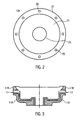
- FIG. 12 shows a plan view of the left half 11A of the two parts / halves 11A and 11B of the turbine housing of the turbocharger 10, as in FIG FIG. 1 shown.
- the selection of the half 11A is to be understood as merely exemplary, and the half 11B and possible further parts (not shown here) can be considered in the same way.
- Half / part 11A as in FIG. 2
- This is typically a smooth sealing surface, which can be contacted with a corresponding sealing surface on the part 11 B (not shown here), so that the two surfaces can lie substantially plane and evenly on one another that a good seal can be achieved.
- Screw holes 29 are also indicated. It is understood that the number of screw holes is not fixed and may be selected according to the size and / or requirements of the turbocharger.
- the corresponding sealing surface of the part 11 B may also have screw holes, so that the two halves 11 A and 11 B can be screwed together suitably. It is also possible to weld the two halves 11A and 11B of the turbine housing of the turbocharger 10 together.
- FIG. 3 Again, the two parts 11A and 11B are shown, as they are already based on the FIGS. 1 and 2 have been described. Additionally is in FIG. 3 a thermal insulation 17 is shown.
- the thermal insulation 17 is in FIG. 3 provided between the two parts 11A and 11B.
- the thermal insulation 17 is similar in shape to the shape of the inside of the part 11A so that it can abut against the inside of the part 11A.
- the thermal insulation may be bolted to at least one or typically both parts 11A and 11B. As a result, the thermal insulation 17 between the two halves 11A and 11B can be used and also removed again.
- the thermal insulation 17 may be multi-layered, for example, the thermal insulation of insulating mats and / or insulating shells exist, with an overlying cover plate (not shown here).
- the layers can each be mat-like, fabric-like or net-like.
Landscapes
- Engineering & Computer Science (AREA)
- Mechanical Engineering (AREA)
- General Engineering & Computer Science (AREA)
- Supercharger (AREA)
Description
- Die Erfindung betrifft einen Turbolader für Verbrennungsmotoren gemäß dem Oberbegriff des Patentanspruchs 1.
- Turbolader, auch Abgasturbolader, kurz ATL, genannt, dienen der Leistungssteigerung von Verbrennungsmotoren durch Erhöhung des Treibstoffgemischdurchsatzes pro Arbeitstakt des Verbrennungsmotors.
- Dokument
GB 2 186 328 A - Dokument
EP 1 795 711 A2 offenbart ein Abgassystem mit einem Abgasisolationsmaterial, das wenigstens aus einem eisenhaltigen Material oder einem keramischen Material besteht. - Über das Turbinengehäuse eines Abgasturboladers geht häufig eine große Wärmemenge verloren. Moderne Verbrennungsmotoren besitzen typischerweise Katalysatoren, sogenannte Fahrzeugkatalysatoren. Die Aufgabe des Fahrzeugkatalysators ist beispielsweise die chemische Umwandlung der Verbrennungsschadstoffe Kohlenwasserstoffe (CmHn), Kohlenstoffmonoxid (CO) und Stickoxide (NOx) in die ungiftigen Stoffe Kohlenstoffdioxid (CO2), Wasser (H2O) und Stickstoff (N2) durch Oxidation beziehungsweise Reduktion. Je nach Betriebspunkt des Motors und entsprechenden Betriebsbedingungen können hohe Umwandlungsraten bis in die Nähe von 100 % erreicht werden.
- Um die nötigen Betriebsbedingungen des Fahrzeugkatalysators von beispielsweise einigen hundert Grad Celsius zu erreichen, kann zumindest ein Teil der nötigen Wärme aus dem heißen Abgas entnommen werden. Geht diese Wärme aber über das Turbinengehäuse verloren, so kann die Wärme nicht an den Katalysator abgegeben werden, sondern wird beispielsweise an die Umgebung des Turbinengehäuses abgegeben. Eventuell können die Turbinengehäuse von außen mit einer Wärmedämmung umgeben werden, was allerdings trotzdem einen großen Wärmeeintrag in das Gehäusematerial des Turboladers bedeutet und das Material entsprechend belastet.
- Anspruchsvolle Abgasgrenzwerte, wie sie typischerweise durch moderne Normen gefordert werden, können praktisch nur durch schnelles Aufheizen der Katalysatoren erzielt werden. Hierzu wird zusätzliche Wärmeenergie, beispielsweise zusätzlicher Kraftstoff, also die zusätzliche Verbrennung von Kraftstoff benötigt. Dieses kann aber zumindest vorübergehend zu erhöhtem Ausstoß von CO2, was der Idee der Reduzierung zuwider laufen kann.
- Das Turbinengehäuse des Turboladers kann also aus zwei Hälften bestehen, es können aber ebenso drei oder mehr Teile sein. Diese Teile sind typischerweise scheibenartig bezüglich einer gemeinsamen Mittelachse angeordnet. Das Turbinengehäuse ist also schnittartig in Teile unterteilt, wobei die Schnitte im Wesentlichen senkrecht zur Mittelachse des Turbinengehäuses liegen. Durch die Teilung des Turbinengehäuses in mehrere Teile ist der Turbolader in seinem Inneren besser wartbar und besser zugänglich. Insbesondere kann der Turbolader nach einer vorbestimmten Zeit, etwa einem Wartungsintervall oder zu Reparaturzwecken, geöffnet werden und nach Durchführung der Wartung oder der Reparaturen wieder geschlossen werden.
- In dem Turbolader wie oben beschrieben, können unmittelbar aufeinanderliegende Teile des Turbinengehäuses miteinander verschraubt werden.
- In dem Turbolader wie oben beschrieben können unmittelbar aufeinanderliegende Teile des Turbinengehäuses miteinander verschweißt werden.
- Jeweils zwei aufeinanderliegende Teile des Turbinengehäuses können glatte Flächen, beispielsweise Dichtflächen besitzen. Im Bereich, wo diese Dichtflächen aufeinander liegen, können die Teile miteinander verbunden werden. Zur Verbindung können jeweils zwei Teile etwa verschraubt werden oder verschweißt werden. Insbesondere kann eine Verschraubung relativ einfach wieder gelöst werden. Es ist ebenso möglich, dass beispielsweise bei einem Turbinengehäuse, dass aus vier Teilen besteht, je zwei aufeinander liegende Teile miteinander verschraubt sind und zwei weitere aufeinander liegende Teile miteinander verschweißt sind.
- In dem Turbolader wie oben beschrieben kann zwischen zwei unmittelbar aufeinanderliegenden Teilen des Turbinengehäuses eine thermische Isolierung eingesetzt werden.
- In das Turbinengehäuse des Turboladers kann also typischerweise an seiner Innenwand oder Innenseite eine thermische Isolierung eingebracht werden. Durch die thermische Isolierung kann das die Turbine durchströmende Gas nicht mehr in direktem Kontakt mit der Innenseite des Turboladers kommen. Die Wärme geht nicht mehr oder nur noch zu einem geringen Teil dissipativ verloren. Die Wärme des heißen Abgases kann in größerem Maße zur Erwärmung beispielsweise von Katalysatoren eingesetzt werden. Hierdurch können weiter Vorteile in Bezug auf Einsparungen an Kraftstoff, Senkung von CO2-Emissionen, also Einsparung von CO2, sowie mehr Abgassicherheit erzielt werden.
- In dem Turbolader wie oben beschrieben kann die thermische Isolierung mit wenigstens einem der beiden Teile verschraubt werden kann.
- Die thermische Isolierung ist damit also auswechselbar. Dadurch lässt sich beispielsweise nach einem vorbestimmten Wartungsintervall die thermische Isolierung warten oder austauschen, wodurch die Lebensdauer des Turboladers erhöht werden kann.
- In dem Turbolader wie oben beschrieben kann die thermische Isolierung eine oder mehrere Schichten aufweisen.
- Durch die mehrschichtige Isolierung kann die thermische Isolierung entsprechend den benötigte Temperaturen oder Temperaturfenstern abgestimmt werden. Dabei können die einzelnen Schichten unterschiedlichen Dicken und/oder Dichten und/oder Materialien und/oder Materialmischungen aufweisen. Die mehreren Schichten sind typischerweise übereinander aufgebracht. Es ist ebenso möglich, eine oder mehrere Luftschichten zwischen jeweils anderen Schichten zu haben.
- In dem Turbolader wie oben beschrieben kann die thermische Isolierung aus einer Deckschicht, beispielsweise einem metallischem Deckblech, und ein oder mehreren darunter liegenden Isoliermatten und/oder Isolierschalen bestehen.
- Die ein oder mehreren Schichten können also beispielsweise unter einer Deckschicht angebracht werden. Dabei ist die Deckschicht typischerweise die am weitesten innen liegende Schicht. Es ist ebenso möglich, auch weitere, beispielsweise metallische Schichten zwischen den Isoliermatten und/oder Isolierschalen vorzusehen.
- Es versteht sich, dass die thermische Isolierung typischerweise eine möglichst günstige Strömungsführung berücksichtigt, um neben den guten Isolierungseigenschaften auch die guten Strömungsführungseigenschaften zu berücksichtigen. Die mehreren Schichten oder Isoliermatten und/oder Isolierschalen können aus einem Fasergewebe aus mineralischen Fasern, beispielsweise aus Glas und/oder Silikat und/oder Keramikfasern bestehen. Die lsoliermatten und/oder Isolierschalen können also als Fasermatten und/oder Faserschalen ausgebildet sein.
- Es versteht sich, dass auch mehr als eine thermische Isolierung in den Turbolader eingesetzt werden können, beispielsweise bei vier Teilen eines Turbinengehäuses zwei thermische Isolierungen, also jeweils eine thermische Isolierung zwischen zwei Teilen.
- Der Erfindungsgegenstand wird anhand der nachfolgenden Zeichnungen beispielhaft erläutert.
- Es zeigen:
-
Fig. 1 : eine Schnittzeichnung durch einen erfindungsgemäßen mehrteiligen Turbolader. -
Fig. 2 : eine Draufsicht auf einen Teil des erfindungsgemäßen Turboladers ausFigur 1 . -
Fig. 3 eine Schnittzeichnung eines erfindungsgemäßen Turboladers mit einer Isolierung. - Die
Fig. 1 zeigt eine Schnittzeichnung durch einen Turbolader entsprechend der vorliegenden Erfindung. - In der
Figur 1 ist ein Turbolader 10 in einem Schnitt senkrecht zur Mittelachse 23 des Turboladers gezeigt. Der Gasstrom aus heißem Gas tritt inFigur 1 auf der rechten Seite des Turboladers 10 ein, wie durch den Pfeil 15 angedeutet. Auf der linken Seite des Turboladers 10 tritt der verdichtete Gasstrom aus, wie durch den Pfeil 13 angedeutet ist. - Der Turbolader 10, wie in
Figur 1 dargestellt, besitzt ein Turbinengehäuse, das aus den beiden Teilen 11A und 11B besteht. Die Teilung des Turbinengehäuses in zwei Teile ist rein beispielhaft zu verstehen. Das Turbinengehäuse kann ebenso aus mehreren Teilen bestehen. Diese Teile können, ähnlich wie die Teile 11A und 11B im Wesentlichen senkrecht zur Mittelachse 23 angeordnet sein. - Der Turbolader 10 weist einen Innenraum 21 auf. Der verdichtete Gasstrom tritt auf der linken Seite des Turboladers aus der Öffnung 25 aus. Mit dem Bezugszeichen 18 ist die Teilungslinie, hier gestrichelt gezeichnet, zwischen den beiden Teilen 11A und 11 B des Turbinengehäuses angedeutet. Die beiden Teile, also die beiden Hälften 11A und 11 B des Turbinengehäuses können liegen direkt aufeinander. Sie können geeignet verbunden sein, wie nachfolgend anhand der
Figur 2 erläutert wird. - Die
Figur 2 zeigt eine Draufsicht auf die linke Hälfte 11A der beiden Teile / Hälften 11A und 11 B des Turbinengehäuses des Turboladers 10, wie inFigur 1 dargestellt. Die Auswahl der Hälfte 11A ist rein beispielhaft zu verstehen und die Hälfte 11 B sowie mögliche weiter Teile (hier nicht gezeigt) können genauso betrachtet werden. - Die Hälfte / das Teil 11A, wie in
Figur 2 dargestellt, besitzt eine Dichtfläche 27. Dabei handelt es sich typischerweise um eine glatte Dichtfläche, die sich mit einer entsprechenden Dichtfläche am Teil 11 B (hier nicht gezeigt) kontaktieren lässt, so dass die beiden Flächen im Wesentlichen plan und ebenmäßig aufeinander liegen können, so dass eine gute Dichtung erzielt werden kann. In derFigur 2 sind ferner Schraubenlöcher 29 angedeutet. Es versteht sich, dass die Zahl der Schraubenlöcher nicht festgelegt ist und entsprechend der Größe und/oder den Anforderungen an den Turbolader gewählt werden können. Die entsprechende Dichtfläche des Teils 11 B (hier nicht gezeigt) kann ebenfalls Schraubenlöcher aufweisen, so dass die beiden Hälften 11A und 11 B geeignet miteinander verschraubt werden können. Ebenso ist es möglich, die beiden Hälften 11A und 11 B des Turbinengehäuses des Turboladers 10 miteinander zu verschweißen. - In
Figur 3 sind wiederum die beiden Teile 11A und 11B gezeigt, wie sie bereits anhand derFiguren 1 und2 beschrieben wurden. Zusätzlich ist inFigur 3 eine thermische Isolierung 17 gezeigt. Die thermische Isolierung 17 ist inFigur 3 zwischen den beiden Teilen 11A und 11B vorgesehen. Die thermische Isolierung 17 ist in ihrer Form der Form der Innenseite des Teils 11A ähnlich, so dass sie an der Innenseite des Teils 11A anliegen kann. Die thermische Isolierung kann mit wenigstens einer oder typischerweise mit beiden Teilen 11A und 11 B verschraubt werden. Dadurch kann die thermische Isolierung 17 zwischen die beiden Hälften 11A und 11B eingesetzt werden und auch wieder entnommen werden. Die thermische Isolierung 17 kann mehrschichtig vorgesehen sein, beispielsweise kann die thermische Isolierung aus Isoliermatten und/oder Isolierschalen bestehen, mit einem darüber liegenden Deckblech (hier nicht gezeigt). Die Schichten können jeweils mattenartig, gewebeartig oder netzartig ausgebildet sein. - Es versteht sich, dass in den zuvor beschriebenen Ausführungsbeispielen genannte Merkmale sich nicht auf die speziell in den Figuren gezeigten Kombinationen beschränken, sondern auch in beliebigen anderen Kombinationen möglich sein können.
Claims (7)
- Turbolader (10) für einen Verbrennungsmotor, mit einem Turbinengehäuse (11A, 11 B);
wobei das Turbinengehäuse (11A, 11B) aus mindestens zwei Teilen (11A, 11B) besteht, wobei die Teile (11A, 11 B) bezüglich einer gemeinsamen Mittelachse (23) angeordnet sind, die im Wesentlichen der Gasdurchtrittsrichtung (13, 15) durch den Turbolader (10) entspricht;
wobei zwischen zwei unmittelbar aufeinanderliegenden Teilen (11A, 11 B) des Turbinengehäuses eine thermische Isolierung (17) eingesetzt ist,
wobei die thermische Isolierung (17) in ihrer Form der Form der Innenseite des Teils (11A) ähnlich ist, so dass sie an der Innenseite des Teils (11A) anliegen kann. - Turbolader (10) nach Anspruch 1, wobei unmittelbar aufeinanderliegende Teile (11A, 11B) des Turbinengehäuses miteinander verschraubt werden können.
- Turbolader (10) nach wenigstens einem der Ansprüche 1 oder 2, wobei unmittelbar aufeinanderliegende Teile (11A, 11 B) des Turbinengehäuses miteinander verschweißt werden können.
- Turbolader (10) nach Anspruch 1, wobei die thermische Isolierung (17) mit wenigstens einem der beiden Teile (11A, 11 B) verschraubt ist.
- Turbolader (10) nach wenigstens einem der Ansprüche 1 oder 4, wobei die Isolierung (17) eine oder mehrere Schichten aufweist.
- Turbolader (10) nach wenigstens einem der Ansprüche 1 - 5, wobei die Isolierung (17) aus einer Deckschicht, beispielsweise einem metallischem Deckblech, und ein oder mehreren darunter liegenden Isoliermatten und/oder Isolierschalen besteht.
- Turbolader (10) nach Anspruch 6, wobei die Isoliermatten und/oder Isolierschalen aus einem Fasergewebe aus mineralischen Fasern, beispielsweise aus Glas und/oder Silikat und/oder Keramikfasern bestehen.
Priority Applications (2)
| Application Number | Priority Date | Filing Date | Title |
|---|---|---|---|
| EP20110008919 EP2592230B1 (de) | 2011-11-09 | 2011-11-09 | Mehrteiliges Turbinengehäuse für einen Turbolader |
| ES11008919.0T ES2470322T3 (es) | 2011-11-09 | 2011-11-09 | Carcasa de turbina en varias partes para un turbocargador |
Applications Claiming Priority (1)
| Application Number | Priority Date | Filing Date | Title |
|---|---|---|---|
| EP20110008919 EP2592230B1 (de) | 2011-11-09 | 2011-11-09 | Mehrteiliges Turbinengehäuse für einen Turbolader |
Publications (2)
| Publication Number | Publication Date |
|---|---|
| EP2592230A1 EP2592230A1 (de) | 2013-05-15 |
| EP2592230B1 true EP2592230B1 (de) | 2014-05-07 |
Family
ID=44992485
Family Applications (1)
| Application Number | Title | Priority Date | Filing Date |
|---|---|---|---|
| EP20110008919 Active EP2592230B1 (de) | 2011-11-09 | 2011-11-09 | Mehrteiliges Turbinengehäuse für einen Turbolader |
Country Status (2)
| Country | Link |
|---|---|
| EP (1) | EP2592230B1 (de) |
| ES (1) | ES2470322T3 (de) |
Cited By (1)
| Publication number | Priority date | Publication date | Assignee | Title |
|---|---|---|---|---|
| US9810238B2 (en) | 2015-03-09 | 2017-11-07 | Caterpillar Inc. | Turbocharger with turbine shroud |
Family Cites Families (5)
| Publication number | Priority date | Publication date | Assignee | Title |
|---|---|---|---|---|
| DE7627763U1 (de) * | 1976-09-04 | 1977-12-29 | Motoren- Und Turbinen-Union Friedrichshafen Gmbh, 7990 Friedrichshafen | Abgasturbolader |
| GB2186328A (en) * | 1986-02-11 | 1987-08-12 | Ishikawajima Harima Heavy Ind | Turbine housings for turbochargers |
| DE10218436C1 (de) * | 2002-04-25 | 2003-08-14 | Benteler Automobiltechnik Gmbh | Abgasturbine für einen Turbolader |
| DE102004025049A1 (de) * | 2004-05-18 | 2005-12-15 | Forschungszentrum Jülich GmbH | Abgasturbolader |
| DE102009007734A1 (de) * | 2009-02-05 | 2010-08-12 | Daimler Ag | Turbinengehäuse für einen Abgasturbolader eines Antriebsaggregats und Verfahren zum Herstellen eines Turbinengehäuses |
-
2011
- 2011-11-09 ES ES11008919.0T patent/ES2470322T3/es active Active
- 2011-11-09 EP EP20110008919 patent/EP2592230B1/de active Active
Cited By (1)
| Publication number | Priority date | Publication date | Assignee | Title |
|---|---|---|---|---|
| US9810238B2 (en) | 2015-03-09 | 2017-11-07 | Caterpillar Inc. | Turbocharger with turbine shroud |
Also Published As
| Publication number | Publication date |
|---|---|
| EP2592230A1 (de) | 2013-05-15 |
| ES2470322T3 (es) | 2014-06-23 |
Similar Documents
| Publication | Publication Date | Title |
|---|---|---|
| EP2440759B1 (de) | Abgasbehandlungsvorrichtung für den motornahen einsatz | |
| EP1440226B1 (de) | Offener partikelfilter mit heizelement | |
| EP1999362B1 (de) | Anordnung mit einem geschützten turbolader in der abgasrückführleitung | |
| DE112018000203T5 (de) | Wärmeaustauschelement, Wärmetauscher und Wärmetauscher mit Reinigungseinrichtung | |
| DE102007048666A1 (de) | Twin-scroll Abgasturbolader | |
| EP2191105A1 (de) | Mehrschichtiger abschirmungsring für einen flugantrieb | |
| DE20117873U1 (de) | Offener Filterkörper mit verbesserten Strömungseigenschaften | |
| EP2691615B1 (de) | Abgasreinigungsvorrichtung für ein wasserfahrzeug und ein verfahren zum betrieb einer abgasreinigungsvorrichtung | |
| EP2977577B1 (de) | Abgassystem und kraftfahrzeug | |
| DE10144293A1 (de) | Ventilkomponentensatz für interne Bypass-Strömung | |
| DE102016215290B4 (de) | Komponente eines Abgassystems und Verfahren zur Abgasnachbehandlung | |
| EP3034837B1 (de) | Kühlluftzufuhrvorrichtung für eine Gasturbine | |
| DE102006007763A1 (de) | Gasturbinen-Abgasdiffusor | |
| EP2446127B1 (de) | Dichteinheit | |
| EP2592240A1 (de) | Turbolader-Turbinengehäuse mit Innenisolierung | |
| EP3674523B1 (de) | Abgasnachbehandlungssystem für einen verbrennungsmotor | |
| DE102013111033A1 (de) | Verfahren und Vorrichtung für Thermomanagement einer Kfz-Abgasanlage | |
| EP2592230A1 (de) | Mehrteiliges Turbinengehäuse für einen Turbolader | |
| WO2009138068A1 (de) | Mischdüsenaufbau | |
| DE202011111090U1 (de) | Turbolader mit Innenisolierung | |
| DE102015104591A1 (de) | Abgaskanal einer Brennkraftmaschine, insbesondere mit Abgasturbolader, sowie Brennkraftmaschine mit einem solchen Abgaskanal | |
| DE102010008273B4 (de) | Partikelfilteranordnung | |
| EP2069616B1 (de) | Vorrichtung zur entfernung von russpartikeln aus dem abgasstrom einer brennkraftmaschine | |
| EP1391591B1 (de) | Vorrichtung zum Reinigen von Abgasen von Brennkraftmaschinen | |
| DE102017215563A1 (de) | Partikelfilter für die Abgasnachbehandlung eines Verbrennungsmotors |
Legal Events
| Date | Code | Title | Description |
|---|---|---|---|
| PUAI | Public reference made under article 153(3) epc to a published international application that has entered the european phase |
Free format text: ORIGINAL CODE: 0009012 |
|
| AK | Designated contracting states |
Kind code of ref document: A1 Designated state(s): AL AT BE BG CH CY CZ DE DK EE ES FI FR GB GR HR HU IE IS IT LI LT LU LV MC MK MT NL NO PL PT RO RS SE SI SK SM TR |
|
| AX | Request for extension of the european patent |
Extension state: BA ME |
|
| 17P | Request for examination filed |
Effective date: 20131114 |
|
| RBV | Designated contracting states (corrected) |
Designated state(s): AL AT BE BG CH CY CZ DE DK EE ES FI FR GB GR HR HU IE IS IT LI LT LU LV MC MK MT NL NO PL PT RO RS SE SI SK SM TR |
|
| GRAP | Despatch of communication of intention to grant a patent |
Free format text: ORIGINAL CODE: EPIDOSNIGR1 |
|
| RIC1 | Information provided on ipc code assigned before grant |
Ipc: F01D 25/14 20060101ALI20131203BHEP Ipc: F01D 25/24 20060101ALI20131203BHEP Ipc: F01D 9/02 20060101AFI20131203BHEP |
|
| INTG | Intention to grant announced |
Effective date: 20140102 |
|
| RIN1 | Information on inventor provided before grant (corrected) |
Inventor name: HENKE, WALDEMAR Inventor name: HOECKER, PATRIC Inventor name: LOIBL, WERNER Inventor name: OBERTHUER, HOLGER Inventor name: KROLL, MATTHIAS Inventor name: MUENZ, STEFAN |
|
| GRAS | Grant fee paid |
Free format text: ORIGINAL CODE: EPIDOSNIGR3 |
|
| GRAA | (expected) grant |
Free format text: ORIGINAL CODE: 0009210 |
|
| AK | Designated contracting states |
Kind code of ref document: B1 Designated state(s): AL AT BE BG CH CY CZ DE DK EE ES FI FR GB GR HR HU IE IS IT LI LT LU LV MC MK MT NL NO PL PT RO RS SE SI SK SM TR |
|
| REG | Reference to a national code |
Ref country code: GB Ref legal event code: FG4D Free format text: NOT ENGLISH |
|
| REG | Reference to a national code |
Ref country code: AT Ref legal event code: REF Ref document number: 666881 Country of ref document: AT Kind code of ref document: T Effective date: 20140515 |
|
| REG | Reference to a national code |
Ref country code: IE Ref legal event code: FG4D Free format text: LANGUAGE OF EP DOCUMENT: GERMAN |
|
| REG | Reference to a national code |
Ref country code: ES Ref legal event code: FG2A Ref document number: 2470322 Country of ref document: ES Kind code of ref document: T3 Effective date: 20140623 |
|
| REG | Reference to a national code |
Ref country code: DE Ref legal event code: R096 Ref document number: 502011002962 Country of ref document: DE Effective date: 20140626 |
|
| REG | Reference to a national code |
Ref country code: NL Ref legal event code: VDEP Effective date: 20140507 |
|
| REG | Reference to a national code |
Ref country code: LT Ref legal event code: MG4D |
|
| PG25 | Lapsed in a contracting state [announced via postgrant information from national office to epo] |
Ref country code: FI Free format text: LAPSE BECAUSE OF FAILURE TO SUBMIT A TRANSLATION OF THE DESCRIPTION OR TO PAY THE FEE WITHIN THE PRESCRIBED TIME-LIMIT Effective date: 20140507 Ref country code: NO Free format text: LAPSE BECAUSE OF FAILURE TO SUBMIT A TRANSLATION OF THE DESCRIPTION OR TO PAY THE FEE WITHIN THE PRESCRIBED TIME-LIMIT Effective date: 20140807 Ref country code: GR Free format text: LAPSE BECAUSE OF FAILURE TO SUBMIT A TRANSLATION OF THE DESCRIPTION OR TO PAY THE FEE WITHIN THE PRESCRIBED TIME-LIMIT Effective date: 20140808 Ref country code: CY Free format text: LAPSE BECAUSE OF FAILURE TO SUBMIT A TRANSLATION OF THE DESCRIPTION OR TO PAY THE FEE WITHIN THE PRESCRIBED TIME-LIMIT Effective date: 20140507 Ref country code: LT Free format text: LAPSE BECAUSE OF FAILURE TO SUBMIT A TRANSLATION OF THE DESCRIPTION OR TO PAY THE FEE WITHIN THE PRESCRIBED TIME-LIMIT Effective date: 20140507 Ref country code: IS Free format text: LAPSE BECAUSE OF FAILURE TO SUBMIT A TRANSLATION OF THE DESCRIPTION OR TO PAY THE FEE WITHIN THE PRESCRIBED TIME-LIMIT Effective date: 20140907 |
|
| PG25 | Lapsed in a contracting state [announced via postgrant information from national office to epo] |
Ref country code: SE Free format text: LAPSE BECAUSE OF FAILURE TO SUBMIT A TRANSLATION OF THE DESCRIPTION OR TO PAY THE FEE WITHIN THE PRESCRIBED TIME-LIMIT Effective date: 20140507 Ref country code: RS Free format text: LAPSE BECAUSE OF FAILURE TO SUBMIT A TRANSLATION OF THE DESCRIPTION OR TO PAY THE FEE WITHIN THE PRESCRIBED TIME-LIMIT Effective date: 20140507 Ref country code: PL Free format text: LAPSE BECAUSE OF FAILURE TO SUBMIT A TRANSLATION OF THE DESCRIPTION OR TO PAY THE FEE WITHIN THE PRESCRIBED TIME-LIMIT Effective date: 20140507 Ref country code: LV Free format text: LAPSE BECAUSE OF FAILURE TO SUBMIT A TRANSLATION OF THE DESCRIPTION OR TO PAY THE FEE WITHIN THE PRESCRIBED TIME-LIMIT Effective date: 20140507 Ref country code: HR Free format text: LAPSE BECAUSE OF FAILURE TO SUBMIT A TRANSLATION OF THE DESCRIPTION OR TO PAY THE FEE WITHIN THE PRESCRIBED TIME-LIMIT Effective date: 20140507 |
|
| PG25 | Lapsed in a contracting state [announced via postgrant information from national office to epo] |
Ref country code: PT Free format text: LAPSE BECAUSE OF FAILURE TO SUBMIT A TRANSLATION OF THE DESCRIPTION OR TO PAY THE FEE WITHIN THE PRESCRIBED TIME-LIMIT Effective date: 20140908 |
|
| PG25 | Lapsed in a contracting state [announced via postgrant information from national office to epo] |
Ref country code: RO Free format text: LAPSE BECAUSE OF FAILURE TO SUBMIT A TRANSLATION OF THE DESCRIPTION OR TO PAY THE FEE WITHIN THE PRESCRIBED TIME-LIMIT Effective date: 20140507 Ref country code: CZ Free format text: LAPSE BECAUSE OF FAILURE TO SUBMIT A TRANSLATION OF THE DESCRIPTION OR TO PAY THE FEE WITHIN THE PRESCRIBED TIME-LIMIT Effective date: 20140507 Ref country code: SK Free format text: LAPSE BECAUSE OF FAILURE TO SUBMIT A TRANSLATION OF THE DESCRIPTION OR TO PAY THE FEE WITHIN THE PRESCRIBED TIME-LIMIT Effective date: 20140507 Ref country code: EE Free format text: LAPSE BECAUSE OF FAILURE TO SUBMIT A TRANSLATION OF THE DESCRIPTION OR TO PAY THE FEE WITHIN THE PRESCRIBED TIME-LIMIT Effective date: 20140507 Ref country code: DK Free format text: LAPSE BECAUSE OF FAILURE TO SUBMIT A TRANSLATION OF THE DESCRIPTION OR TO PAY THE FEE WITHIN THE PRESCRIBED TIME-LIMIT Effective date: 20140507 |
|
| REG | Reference to a national code |
Ref country code: DE Ref legal event code: R097 Ref document number: 502011002962 Country of ref document: DE |
|
| PG25 | Lapsed in a contracting state [announced via postgrant information from national office to epo] |
Ref country code: NL Free format text: LAPSE BECAUSE OF FAILURE TO SUBMIT A TRANSLATION OF THE DESCRIPTION OR TO PAY THE FEE WITHIN THE PRESCRIBED TIME-LIMIT Effective date: 20140507 |
|
| PLBE | No opposition filed within time limit |
Free format text: ORIGINAL CODE: 0009261 |
|
| STAA | Information on the status of an ep patent application or granted ep patent |
Free format text: STATUS: NO OPPOSITION FILED WITHIN TIME LIMIT |
|
| 26N | No opposition filed |
Effective date: 20150210 |
|
| REG | Reference to a national code |
Ref country code: DE Ref legal event code: R097 Ref document number: 502011002962 Country of ref document: DE Effective date: 20150210 |
|
| PG25 | Lapsed in a contracting state [announced via postgrant information from national office to epo] |
Ref country code: LU Free format text: LAPSE BECAUSE OF FAILURE TO SUBMIT A TRANSLATION OF THE DESCRIPTION OR TO PAY THE FEE WITHIN THE PRESCRIBED TIME-LIMIT Effective date: 20141109 Ref country code: MC Free format text: LAPSE BECAUSE OF FAILURE TO SUBMIT A TRANSLATION OF THE DESCRIPTION OR TO PAY THE FEE WITHIN THE PRESCRIBED TIME-LIMIT Effective date: 20140507 Ref country code: BE Free format text: LAPSE BECAUSE OF NON-PAYMENT OF DUE FEES Effective date: 20141130 |
|
| REG | Reference to a national code |
Ref country code: CH Ref legal event code: PL |
|
| PG25 | Lapsed in a contracting state [announced via postgrant information from national office to epo] |
Ref country code: SI Free format text: LAPSE BECAUSE OF FAILURE TO SUBMIT A TRANSLATION OF THE DESCRIPTION OR TO PAY THE FEE WITHIN THE PRESCRIBED TIME-LIMIT Effective date: 20140507 Ref country code: CH Free format text: LAPSE BECAUSE OF NON-PAYMENT OF DUE FEES Effective date: 20141130 Ref country code: LI Free format text: LAPSE BECAUSE OF NON-PAYMENT OF DUE FEES Effective date: 20141130 |
|
| REG | Reference to a national code |
Ref country code: IE Ref legal event code: MM4A |
|
| PG25 | Lapsed in a contracting state [announced via postgrant information from national office to epo] |
Ref country code: IE Free format text: LAPSE BECAUSE OF NON-PAYMENT OF DUE FEES Effective date: 20141109 |
|
| REG | Reference to a national code |
Ref country code: FR Ref legal event code: PLFP Year of fee payment: 5 |
|
| PG25 | Lapsed in a contracting state [announced via postgrant information from national office to epo] |
Ref country code: SM Free format text: LAPSE BECAUSE OF FAILURE TO SUBMIT A TRANSLATION OF THE DESCRIPTION OR TO PAY THE FEE WITHIN THE PRESCRIBED TIME-LIMIT Effective date: 20140507 |
|
| PG25 | Lapsed in a contracting state [announced via postgrant information from national office to epo] |
Ref country code: BG Free format text: LAPSE BECAUSE OF FAILURE TO SUBMIT A TRANSLATION OF THE DESCRIPTION OR TO PAY THE FEE WITHIN THE PRESCRIBED TIME-LIMIT Effective date: 20140507 |
|
| PG25 | Lapsed in a contracting state [announced via postgrant information from national office to epo] |
Ref country code: HU Free format text: LAPSE BECAUSE OF FAILURE TO SUBMIT A TRANSLATION OF THE DESCRIPTION OR TO PAY THE FEE WITHIN THE PRESCRIBED TIME-LIMIT; INVALID AB INITIO Effective date: 20111109 Ref country code: MT Free format text: LAPSE BECAUSE OF FAILURE TO SUBMIT A TRANSLATION OF THE DESCRIPTION OR TO PAY THE FEE WITHIN THE PRESCRIBED TIME-LIMIT Effective date: 20140507 Ref country code: TR Free format text: LAPSE BECAUSE OF FAILURE TO SUBMIT A TRANSLATION OF THE DESCRIPTION OR TO PAY THE FEE WITHIN THE PRESCRIBED TIME-LIMIT Effective date: 20140507 |
|
| REG | Reference to a national code |
Ref country code: FR Ref legal event code: PLFP Year of fee payment: 6 |
|
| REG | Reference to a national code |
Ref country code: FR Ref legal event code: PLFP Year of fee payment: 7 |
|
| REG | Reference to a national code |
Ref country code: AT Ref legal event code: MM01 Ref document number: 666881 Country of ref document: AT Kind code of ref document: T Effective date: 20161109 |
|
| PG25 | Lapsed in a contracting state [announced via postgrant information from national office to epo] |
Ref country code: AT Free format text: LAPSE BECAUSE OF NON-PAYMENT OF DUE FEES Effective date: 20161109 |
|
| PG25 | Lapsed in a contracting state [announced via postgrant information from national office to epo] |
Ref country code: MK Free format text: LAPSE BECAUSE OF FAILURE TO SUBMIT A TRANSLATION OF THE DESCRIPTION OR TO PAY THE FEE WITHIN THE PRESCRIBED TIME-LIMIT Effective date: 20140507 |
|
| PG25 | Lapsed in a contracting state [announced via postgrant information from national office to epo] |
Ref country code: AL Free format text: LAPSE BECAUSE OF FAILURE TO SUBMIT A TRANSLATION OF THE DESCRIPTION OR TO PAY THE FEE WITHIN THE PRESCRIBED TIME-LIMIT Effective date: 20140507 |
|
| PGFP | Annual fee paid to national office [announced via postgrant information from national office to epo] |
Ref country code: DE Payment date: 20251128 Year of fee payment: 15 |
|
| PGFP | Annual fee paid to national office [announced via postgrant information from national office to epo] |
Ref country code: GB Payment date: 20251127 Year of fee payment: 15 |
|
| PGFP | Annual fee paid to national office [announced via postgrant information from national office to epo] |
Ref country code: IT Payment date: 20251128 Year of fee payment: 15 |
|
| PGFP | Annual fee paid to national office [announced via postgrant information from national office to epo] |
Ref country code: FR Payment date: 20251127 Year of fee payment: 15 |
|
| PGFP | Annual fee paid to national office [announced via postgrant information from national office to epo] |
Ref country code: ES Payment date: 20251201 Year of fee payment: 15 |