EP2592028B1 - Grain sweep conveyor - Google Patents
Grain sweep conveyor Download PDFInfo
- Publication number
- EP2592028B1 EP2592028B1 EP20120192057 EP12192057A EP2592028B1 EP 2592028 B1 EP2592028 B1 EP 2592028B1 EP 20120192057 EP20120192057 EP 20120192057 EP 12192057 A EP12192057 A EP 12192057A EP 2592028 B1 EP2592028 B1 EP 2592028B1
- Authority
- EP
- European Patent Office
- Prior art keywords
- bottom wall
- floor
- grain
- paddle
- sweep
- Prior art date
- Legal status (The legal status is an assumption and is not a legal conclusion. Google has not performed a legal analysis and makes no representation as to the accuracy of the status listed.)
- Active
Links
Images


Classifications
-
- B—PERFORMING OPERATIONS; TRANSPORTING
- B65—CONVEYING; PACKING; STORING; HANDLING THIN OR FILAMENTARY MATERIAL
- B65G—TRANSPORT OR STORAGE DEVICES, e.g. CONVEYORS FOR LOADING OR TIPPING, SHOP CONVEYOR SYSTEMS OR PNEUMATIC TUBE CONVEYORS
- B65G65/00—Loading or unloading
- B65G65/30—Methods or devices for filling or emptying bunkers, hoppers, tanks, or like containers, of interest apart from their use in particular chemical or physical processes or their application in particular machines, e.g. not covered by a single other subclass
- B65G65/34—Emptying devices
- B65G65/40—Devices for emptying otherwise than from the top
- B65G65/42—Devices for emptying otherwise than from the top using belt or chain conveyors
- B65G65/425—Devices for emptying otherwise than from the top using belt or chain conveyors arranged to be movable
-
- B—PERFORMING OPERATIONS; TRANSPORTING
- B65—CONVEYING; PACKING; STORING; HANDLING THIN OR FILAMENTARY MATERIAL
- B65G—TRANSPORT OR STORAGE DEVICES, e.g. CONVEYORS FOR LOADING OR TIPPING, SHOP CONVEYOR SYSTEMS OR PNEUMATIC TUBE CONVEYORS
- B65G23/00—Driving gear for endless conveyors; Belt- or chain-tensioning arrangements
-
- B—PERFORMING OPERATIONS; TRANSPORTING
- B65—CONVEYING; PACKING; STORING; HANDLING THIN OR FILAMENTARY MATERIAL
- B65G—TRANSPORT OR STORAGE DEVICES, e.g. CONVEYORS FOR LOADING OR TIPPING, SHOP CONVEYOR SYSTEMS OR PNEUMATIC TUBE CONVEYORS
- B65G65/00—Loading or unloading
- B65G65/30—Methods or devices for filling or emptying bunkers, hoppers, tanks, or like containers, of interest apart from their use in particular chemical or physical processes or their application in particular machines, e.g. not covered by a single other subclass
- B65G65/34—Emptying devices
- B65G65/40—Devices for emptying otherwise than from the top
- B65G65/42—Devices for emptying otherwise than from the top using belt or chain conveyors
-
- B—PERFORMING OPERATIONS; TRANSPORTING
- B65—CONVEYING; PACKING; STORING; HANDLING THIN OR FILAMENTARY MATERIAL
- B65G—TRANSPORT OR STORAGE DEVICES, e.g. CONVEYORS FOR LOADING OR TIPPING, SHOP CONVEYOR SYSTEMS OR PNEUMATIC TUBE CONVEYORS
- B65G65/00—Loading or unloading
- B65G65/30—Methods or devices for filling or emptying bunkers, hoppers, tanks, or like containers, of interest apart from their use in particular chemical or physical processes or their application in particular machines, e.g. not covered by a single other subclass
- B65G65/34—Emptying devices
- B65G65/40—Devices for emptying otherwise than from the top
- B65G65/46—Devices for emptying otherwise than from the top using screw conveyors
-
- B—PERFORMING OPERATIONS; TRANSPORTING
- B65—CONVEYING; PACKING; STORING; HANDLING THIN OR FILAMENTARY MATERIAL
- B65G—TRANSPORT OR STORAGE DEVICES, e.g. CONVEYORS FOR LOADING OR TIPPING, SHOP CONVEYOR SYSTEMS OR PNEUMATIC TUBE CONVEYORS
- B65G69/00—Auxiliary measures taken, or devices used, in connection with loading or unloading
- B65G69/08—Devices for emptying storage spaces as completely as possible
Definitions
- the present invention relates to a grain sweep for use on a floor comprising an elongated frame, said frame comprising an elongated hood comprising a top panel and first and second side walls, a first and a second wheel rotatably attached to said elongated frame adjacent a first and a second end of said elongated frame, respectively, a drive means passing about said first and second wheels, and a plurality of spaced apart paddles arranged on said drive means.
- conveyors are generally used for moving bulk granules substances such as for instance wheat, oats, rye, barley, shelled or ground corn.
- Storage means for such substances could for example be a silo or a storage bin.
- Sweep means are used to convey this residue to the opening, originally human, today more often a sweep conveyor, which is generally radially disposed and movable about the opening to sweep the granules towards the opening.
- this conveyor is an auger.
- An alternative type of conveyor is a so called bin paddle sweep.
- This type of conveyor normally includes an elongated frame, a first sprocket at one end of the frame and a second sprocket at the other end of the frame, an endless chain extending between the first and the second sprockets, a plurality of spaced apart paddles attached to the chain, and a motor for causing the chain to rotate whereby the paddles will drag or sweep grain to the well in the floor of the grain bin. Since the conveyors are relatively long there might be a problem with the paddles not travelling in the intended path. Further, these conveyors generally also have a hood with a top panel and side walls.
- the side wall facing the grain to be conveyed does not reach down to the floor of the bin, whereas the other as far as possible goes all the way down. However, not all of the grain will be conveyed since some will pass the paddles and under the side wall reaching the closest to the floor.
- US 6,499,930 discloses an unloading system for a grain bin.
- the unloading system includes a sweep conveyor for sweeping grain from the interior of the grain bin to a well in the floor of the grain bin.
- the sweep conveyor includes an elongated frame, a first sprocket at one end of the frame, a second sprocket at the other end of the frame, an endless chain extending between the first and second sprockets, a plurality of spaced apart paddles attached to the chain, and a motor for causing the chain to rotate whereby the paddles will drag or sweep grain to the well in the floor of the grain bin.
- US 2006/0269383 discloses a terminal elevator drive wheel for a grain bin sweep auger.
- the sweep auger drive wheel has angled spaced peripheral inward extending blades, which agitates granules at the outer edge of the storage bin in front of the drive wheel. The blades simultaneously provide contact with the floor of the storage bin, and propel the auger forward into the granules.
- the object of the present invention is to provide an improved grain sweep.
- a grain sweep for use on a floor comprising an elongated frame.
- Said frame comprises an elongated hood comprising a top panel and first and second side walls, a first and a second wheel rotatably attached to said elongated frame adjacent a first and a second end of said elongated frame, respectively.
- a drive means is further provided for passing about said first and second wheels and a plurality of spaced apart paddles arranged on said drive means.
- the hood further comprises one bottom wall extending from one of said side walls and at least one paddle comprising a side with one part adjacent the bottom wall and parallel with the floor and one part with corresponding shape to the bottom wall.
- the drive means is typically a chain but could alternatively be some kind of belt or similar.
- the bottom wall provides for a lower friction control of the paddle path, i.e. instead of the entire edge facing the inner side wall rubbing against the wall, a small piece of the outer part of the paddle adjacent the bottom wall will slide against the edge of the bottom wall.
- the edge of the paddle closest to the floor will have a stepped profile, one part above the bottom wall and the other part immediately above the floor, i.e. the edge of the at least one paddle part adjacent the bottom wall and parallel with the floor stretches further towards the floor than the other paddle part.
- the bottom wall is parallel with the floor. This means that the paddle edges of the two parts will be parallel to one another.
- the bottom wall is at an angle larger than 1° versus the floor.
- the idea is to have a slope towards the point dividing the paddle edge into the two parts, thereby decreasing build up of grains on the inner side wall.
- the edge of the bottom wall has a ridge reaching inwardly the hood.
- the paddles will have a correspondingly shaped notch or recess.
- the travelling path of the paddles will be more controlled and their movement laterally will be limited.
- the cross section of the ridge could have an inverted V-shape or a sinus shape. Other shapes are of course possible as long as the ridge is not to high preventing grains from moving from one side of the ridge to the other.
- the plane of the one part of the paddles with a corresponding shape to the bottom wall is perpendicular to the direction of the paddles movement.
- An alternative is to have the paddles angled such that the grains will move towards the other part of the paddle when the paddle is moving forward.
- the plane of the part of the paddle with an edge parallel with the floor is at an angle larger than 1° to the plane of the other part of the paddle.
- a drive wheel For moving the grain sweep laterally there is provided a drive wheel at least at one end of the grain sweep.
- a grain sweep 1 for use on a floor comprising an elongated frame
- said frame comprises an elongated hood 2 comprising a top panel 3 and first 4 and second 5 side walls, a first 6 and a second wheel rotatably attached to said elongated frame adjacent a first and a second end of said elongated frame, respectively, a drive means 7 passing about said first 6 and second wheels, and a plurality of spaced apart paddles 8 arranged on said drive means 7.
- the hood 2 further comprises one bottom wall 9 extending from one of said side walls 4 and one paddle 10 that comprises a side with one part 11 adjacent the bottom wall 9 and parallel with the floor and one part 12 with corresponding shape to the bottom wall 9.
- the edge of the bottom wall 9 has a ridge 13 reaching inwardly the hood 2.
- the cross section is in the shown embodiment of the ridge 13 an inverted V-shape. Alternatively, the cross section of the ridge could be sinus shaped (not shown).
- the paddles 8, 10 have a recess 14 corresponding to the ridge 13 on the bottom wall 9 of the hood 2.
- the plane of the one part 12 of the paddles 8, 10 with a corresponding shape to the bottom wall 9 is perpendicular to the direction of the paddles 8, 10 movement. Further, the edge of the at least one paddle part 11 adjacent the bottom wall and parallel with the floor stretches further towards the floor than the other paddle part 12.
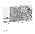
- FIGS. 2 and 3 show a drive wheel 15, not part of the invention, for moving a grain sweep 1.
- the drive wheel 15 is attached at one end of the frame.
- the drive wheel 15 comprising a circular plate 16 of material, a plurality of elongate folded plates 17 attached to one side of said circular plate 16 and distributed like spokes on a wheel with one end of each folded elongate plate pointing towards the centre part of the circular plate 16 and the other end pointing towards the periphery of the circular plate 16.
- the elongate folded plates 17 could for instance be welded to the circular plate 16.
- Floor contacting parts 18 are attached to the elongate folded plates 17 at the ends pointing towards the periphery of the circular plate 16. They are further arranged such that the floor contacting parts 18 extend beyond the periphery of the circular plate 16.
- the floor contacting parts 18 are further arranged at an angle relative the plane of the circular plate 16 such that grains are moved towards the grain transporting parts of the grain sweep 1 upon rotation of the drive wheel 15.
- the floor contacting parts 18 are made from a material comprising rubber.
- every sixth paddle has a part that will rub against the floor when the grain sweep is in use.
- every seventh or every fifth paddle should be such a paddle.
Landscapes
- Engineering & Computer Science (AREA)
- Mechanical Engineering (AREA)
- Storage Of Harvested Produce (AREA)
- Drying Of Solid Materials (AREA)
- Filling Or Emptying Of Bunkers, Hoppers, And Tanks (AREA)
Description
- The present invention relates to a grain sweep for use on a floor comprising an elongated frame, said frame comprising an elongated hood comprising a top panel and first and second side walls, a first and a second wheel rotatably attached to said elongated frame adjacent a first and a second end of said elongated frame, respectively, a drive means passing about said first and second wheels, and a plurality of spaced apart paddles arranged on said drive means.
- For moving bulk granules substances such as for instance wheat, oats, rye, barley, shelled or ground corn, conveyors are generally used. Storage means for such substances could for example be a silo or a storage bin. When storage means are emptied, first gravity feeds the granules into an outlet opening formed in the centre of the storage mean, leaving a substantial residue forming an inverted cone outward from the opening. Sweep means are used to convey this residue to the opening, originally human, today more often a sweep conveyor, which is generally radially disposed and movable about the opening to sweep the granules towards the opening. Conventionally this conveyor is an auger.
- An alternative type of conveyor is a so called bin paddle sweep. This type of conveyor normally includes an elongated frame, a first sprocket at one end of the frame and a second sprocket at the other end of the frame, an endless chain extending between the first and the second sprockets, a plurality of spaced apart paddles attached to the chain, and a motor for causing the chain to rotate whereby the paddles will drag or sweep grain to the well in the floor of the grain bin. Since the conveyors are relatively long there might be a problem with the paddles not travelling in the intended path. Further, these conveyors generally also have a hood with a top panel and side walls. The side wall facing the grain to be conveyed does not reach down to the floor of the bin, whereas the other as far as possible goes all the way down. However, not all of the grain will be conveyed since some will pass the paddles and under the side wall reaching the closest to the floor.
-
US 6,499,930 discloses an unloading system for a grain bin. The unloading system includes a sweep conveyor for sweeping grain from the interior of the grain bin to a well in the floor of the grain bin. The sweep conveyor includes an elongated frame, a first sprocket at one end of the frame, a second sprocket at the other end of the frame, an endless chain extending between the first and second sprockets, a plurality of spaced apart paddles attached to the chain, and a motor for causing the chain to rotate whereby the paddles will drag or sweep grain to the well in the floor of the grain bin. -
US 2006/0269383 discloses a terminal elevator drive wheel for a grain bin sweep auger. The sweep auger drive wheel has angled spaced peripheral inward extending blades, which agitates granules at the outer edge of the storage bin in front of the drive wheel. The blades simultaneously provide contact with the floor of the storage bin, and propel the auger forward into the granules. - The object of the present invention is to provide an improved grain sweep.
- This object is achieved by the grain sweep as set forth in the appended claims.
- According to the present invention a grain sweep is provided for use on a floor comprising an elongated frame. Said frame comprises an elongated hood comprising a top panel and first and second side walls, a first and a second wheel rotatably attached to said elongated frame adjacent a first and a second end of said elongated frame, respectively. A drive means is further provided for passing about said first and second wheels and a plurality of spaced apart paddles arranged on said drive means. The hood further comprises one bottom wall extending from one of said side walls and at least one paddle comprising a side with one part adjacent the bottom wall and parallel with the floor and one part with corresponding shape to the bottom wall.
- The drive means is typically a chain but could alternatively be some kind of belt or similar. The bottom wall provides for a lower friction control of the paddle path, i.e. instead of the entire edge facing the inner side wall rubbing against the wall, a small piece of the outer part of the paddle adjacent the bottom wall will slide against the edge of the bottom wall. Thus, when the paddle is in the working position, the edge of the paddle closest to the floor will have a stepped profile, one part above the bottom wall and the other part immediately above the floor, i.e. the edge of the at least one paddle part adjacent the bottom wall and parallel with the floor stretches further towards the floor than the other paddle part. Not all paddles need to have an edge with two parts, by only having every second or every third paddle with two parts the friction against the floor will be lower than if all paddles should be the same, i.e. with two parts where one part rubs against the floor. This frequency can be altered according to wishes, i.e. the paddles with two parts in a grain sweep could range from each of the paddles to every tenth paddle.
- According to one aspect of the present invention, the bottom wall is parallel with the floor. This means that the paddle edges of the two parts will be parallel to one another.
- Alternatively, the bottom wall is at an angle larger than 1° versus the floor. The idea is to have a slope towards the point dividing the paddle edge into the two parts, thereby decreasing build up of grains on the inner side wall.
- According to a further aspect of the present invention the edge of the bottom wall has a ridge reaching inwardly the hood. Thus, the paddles will have a correspondingly shaped notch or recess. The travelling path of the paddles will be more controlled and their movement laterally will be limited. As for the ridge, the cross section of the ridge could have an inverted V-shape or a sinus shape. Other shapes are of course possible as long as the ridge is not to high preventing grains from moving from one side of the ridge to the other.
- According to another aspect of the present invention, the plane of the one part of the paddles with a corresponding shape to the bottom wall is perpendicular to the direction of the paddles movement. An alternative is to have the paddles angled such that the grains will move towards the other part of the paddle when the paddle is moving forward.
- According to yet another aspect of the present invention the plane of the part of the paddle with an edge parallel with the floor is at an angle larger than 1° to the plane of the other part of the paddle. An advantage is that with this solution the grains will more likely be pushed over the ridge on the bottom wall.
- For moving the grain sweep laterally there is provided a drive wheel at least at one end of the grain sweep.
- The invention will now be further disclosed with reference to the accompanying drawings.
-
Figure 1 is a cross section of the grain sweep. -
Figure 2 is a perspective view of a drive wheel and parts of the grain sweep. -
Figure 3 is a perspective view of a grain sweep. - In
figures 1 ,2 and3 can be seen agrain sweep 1 for use on a floor comprising an elongated frame , said frame comprises anelongated hood 2 comprising atop panel 3 and first 4 and second 5 side walls, a first 6 and a second wheel rotatably attached to said elongated frame adjacent a first and a second end of said elongated frame, respectively, a drive means 7 passing about said first 6 and second wheels, and a plurality of spacedapart paddles 8 arranged on saiddrive means 7. - As also can be seen the
hood 2 further comprises onebottom wall 9 extending from one ofsaid side walls 4 and onepaddle 10 that comprises a side with onepart 11 adjacent thebottom wall 9 and parallel with the floor and onepart 12 with corresponding shape to thebottom wall 9. - The edge of the
bottom wall 9 has aridge 13 reaching inwardly thehood 2. The cross section is in the shown embodiment of theridge 13 an inverted V-shape. Alternatively, the cross section of the ridge could be sinus shaped (not shown). Thepaddles recess 14 corresponding to theridge 13 on thebottom wall 9 of thehood 2. - In the shown embodiments the plane of the one
part 12 of thepaddles bottom wall 9 is perpendicular to the direction of thepaddles paddle part 11 adjacent the bottom wall and parallel with the floor stretches further towards the floor than theother paddle part 12. -
Figure 2 and3 show adrive wheel 15, not part of the invention, for moving agrain sweep 1. Infigure 2 can be seen that thedrive wheel 15 is attached at one end of the frame. Thedrive wheel 15 comprising acircular plate 16 of material, a plurality of elongate foldedplates 17 attached to one side of saidcircular plate 16 and distributed like spokes on a wheel with one end of each folded elongate plate pointing towards the centre part of thecircular plate 16 and the other end pointing towards the periphery of thecircular plate 16. The elongate foldedplates 17 could for instance be welded to thecircular plate 16. -
Floor contacting parts 18 are attached to the elongate foldedplates 17 at the ends pointing towards the periphery of thecircular plate 16. They are further arranged such that thefloor contacting parts 18 extend beyond the periphery of thecircular plate 16. - The
floor contacting parts 18 are further arranged at an angle relative the plane of thecircular plate 16 such that grains are moved towards the grain transporting parts of thegrain sweep 1 upon rotation of thedrive wheel 15. In the shown embodiments thefloor contacting parts 18 are made from a material comprising rubber. - The foregoing is a disclosure of an example practicing the present invention. However, it is apparent that modifications and variations will be obvious to one skilled in the art, without departing from the scope of the invention, which is defined by the appended claims. For instance, in
figure 3 , every sixth paddle has a part that will rub against the floor when the grain sweep is in use. However, in some cases it might prove to be better that every seventh or every fifth paddle should be such a paddle.
Claims (10)
- A grain sweep (1) for use on a floor comprising an elongated frame , said frame comprises an elongated hood (2) comprising a top panel (3) and first (4) and second (5) side walls, a first (6) and a second wheel rotatably attached to said elongated frame adjacent a first and a second end of said elongated frame, respectively, a drive means (7) passing about said first (6) and second wheels, and a plurality of spaced apart paddles (8) arranged on said drive means (7),
characterised in
that the hood (2) further comprises one bottom wall (9) extending from one of said side walls and in that at least one paddle (10) comprises a side with a first part (11) adjacent the bottom wall (9) and parallel with the floor and a second part (12) with corresponding shape to the bottom wall (9). - A grain sweep (1) according to claim 1, wherein the bottom wall (9) is parallel with the floor.
- A grain sweep (1) according to claim 1, wherein the bottom wall (9) is at an angle larger than 1° versus the floor.
- A grain sweep (1) according to any of the claims 1 and 2, wherein the edge of the bottom wall (9) has a ridge (13) reaching inwardly the hood (2).
- A grain sweep (1) according to claim 4, wherein the cross section of the ridge (13) has an inverted V-shape.
- A grain sweep (1) according to claim 4, wherein the cross section of the ridge is sinus shaped.
- A grain sweep (1) according to any of the claims 4-6, wherein paddles (8, 10) have a recess (14) corresponding to the ridge (13) on the bottom wall (9) of the hood (2).
- A grain sweep (1) according to any of the preceding claims, wherein the plane of the second part (12) of the paddles (8, 10) with a corresponding shape to the bottom wall (9) is perpendicular to the direction of the paddles (8, 10) movement.
- A grain sweep (1) according to any of the preceding claims, wherein the plane of the first part (11) of the paddle (8, 10) with an edge parallel with the floor is at an angle larger than 1° to the plane of the second part (12) of the paddle (8, 10).
- A grain sweep (1) according to any of the preceding claims, wherein the edge of the at least first paddle part (11) adjacent the bottom wall and parallel with the floor stretches further towards the floor than the second paddle part (12).
Priority Applications (1)
| Application Number | Priority Date | Filing Date | Title |
|---|---|---|---|
| PL12192057T PL2592028T3 (en) | 2011-11-11 | 2012-11-09 | Grain sweep conveyor |
Applications Claiming Priority (1)
| Application Number | Priority Date | Filing Date | Title |
|---|---|---|---|
| SE1151071 | 2011-11-11 |
Publications (2)
| Publication Number | Publication Date |
|---|---|
| EP2592028A1 EP2592028A1 (en) | 2013-05-15 |
| EP2592028B1 true EP2592028B1 (en) | 2015-03-18 |
Family
ID=47227525
Family Applications (1)
| Application Number | Title | Priority Date | Filing Date |
|---|---|---|---|
| EP20120192057 Active EP2592028B1 (en) | 2011-11-11 | 2012-11-09 | Grain sweep conveyor |
Country Status (5)
| Country | Link |
|---|---|
| US (1) | US9120633B2 (en) |
| EP (1) | EP2592028B1 (en) |
| DK (1) | DK2592028T3 (en) |
| HU (1) | HUE025932T2 (en) |
| PL (1) | PL2592028T3 (en) |
Families Citing this family (12)
| Publication number | Priority date | Publication date | Assignee | Title |
|---|---|---|---|---|
| US10676294B2 (en) | 2011-09-09 | 2020-06-09 | Sioux Steel Company | Modular storage bin sweep system |
| US10442641B2 (en) * | 2014-12-02 | 2019-10-15 | Sioux Steel Company | Bin sweep system |
| WO2016141083A1 (en) | 2015-03-02 | 2016-09-09 | Sioux Steel Company | Bin sweep power transmission system |
| CN105173793B (en) * | 2015-07-27 | 2017-06-09 | 天府重工有限公司 | A kind of railway carriage trusk cleaner |
| US10377573B2 (en) | 2016-03-22 | 2019-08-13 | Sukup Manufacturing Co. | Paddle sweep |
| US10703588B1 (en) | 2017-04-25 | 2020-07-07 | Sioux Steel Company | Bin sweep system with particle agglomeration breakup capability |
| US11225387B2 (en) | 2018-10-01 | 2022-01-18 | Brent J. Bloemendaal | Grain bin sweep apparatus |
| US11454444B1 (en) | 2019-03-08 | 2022-09-27 | Sioux Steel Company | Storage bin ventilation system and apparatus |
| US11267664B1 (en) | 2019-03-08 | 2022-03-08 | Sioux Steel Company | Bin sweep system with drive apparatus having enhanced slippage capability |
| US11299358B1 (en) | 2019-03-08 | 2022-04-12 | Sioux Steel Company | Storage bin sweep system with enhanced peripheral sweep capability |
| US11618639B1 (en) | 2019-03-08 | 2023-04-04 | Sioux Steel Company | Storage bin sweep system with enhanced peripheral sweep capability |
| US11104528B1 (en) | 2019-03-08 | 2021-08-31 | Sioux Steel Company | Bin sweep system with contoured paddles |
Family Cites Families (14)
| Publication number | Priority date | Publication date | Assignee | Title |
|---|---|---|---|---|
| US1969367A (en) | 1931-01-19 | 1934-08-07 | Keith O Guthrie | Pulp wood reclaimer |
| US2944686A (en) * | 1958-11-10 | 1960-07-12 | Smith Corp A O | Shielding device for a drive unit |
| US2948422A (en) * | 1958-11-28 | 1960-08-09 | Smith Corp A O | Floor construction for a storage structure |
| US3456818A (en) * | 1967-11-29 | 1969-07-22 | Speed King Mfg Co Inc | Grain auger apparatus |
| NO154688C (en) * | 1983-10-26 | 1986-12-03 | Kaare Haahjem | BULKGODS CLEANING DEVICE. |
| US5333762A (en) * | 1993-05-07 | 1994-08-02 | Hyer Industries, Inc. | Screw feeder with progressively decreasing screw confinement |
| US5769590A (en) * | 1996-08-29 | 1998-06-23 | Weikel; Charles W. | Grain sweep drive apparatus |
| US6499930B1 (en) | 2001-09-17 | 2002-12-31 | Carl R. Dixon | Grain bin unloading system |
| US7588405B2 (en) * | 2004-01-16 | 2009-09-15 | Grainway, L.L.C. | Incline grain conveyor for grain bins |
| WO2006081523A2 (en) * | 2005-01-28 | 2006-08-03 | Cst Industries, Inc. | Method and apparatus for unloading material from a container |
| US8210342B2 (en) * | 2005-05-26 | 2012-07-03 | Henry Peter Lepp | Sweep auger elevator drive wheel |
| US7331855B2 (en) * | 2005-07-15 | 2008-02-19 | Deere & Company | Wide-spread impeller spreader for harvesting combine |
| CA2650913C (en) * | 2009-01-23 | 2013-10-15 | Sunopta Bioprocess Inc. | Method and apparatus for conveying a cellulosic feedstock |
| US8770388B1 (en) * | 2011-10-19 | 2014-07-08 | Duane Cyril Chaon | Sweep conveyor for removal of grain and other materials from bins |
-
2012
- 2012-11-09 PL PL12192057T patent/PL2592028T3/en unknown
- 2012-11-09 DK DK12192057.3T patent/DK2592028T3/en active
- 2012-11-09 US US13/673,901 patent/US9120633B2/en active Active
- 2012-11-09 HU HUE12192057A patent/HUE025932T2/en unknown
- 2012-11-09 EP EP20120192057 patent/EP2592028B1/en active Active
Also Published As
| Publication number | Publication date |
|---|---|
| PL2592028T3 (en) | 2015-08-31 |
| HUE025932T2 (en) | 2016-05-30 |
| DK2592028T3 (en) | 2015-06-15 |
| EP2592028A1 (en) | 2013-05-15 |
| US20130121794A1 (en) | 2013-05-16 |
| US9120633B2 (en) | 2015-09-01 |
Similar Documents
| Publication | Publication Date | Title |
|---|---|---|
| US9120633B2 (en) | Grain sweep conveyor | |
| US10836582B2 (en) | Paddle sweep | |
| US9181033B2 (en) | Tubular conveyor with cleated belt | |
| US11708227B2 (en) | Sweep auger drive shield with gravity reclaim | |
| CA2740268C (en) | Belt conveyor for oilseeds | |
| US9840381B1 (en) | Auger transfer conveyor | |
| US20080173521A1 (en) | Grain and fertilizer conveyor | |
| US9221616B2 (en) | Tubular conveyor with cleanout having detachable cover | |
| US7124879B1 (en) | Endless belt | |
| CA2932675C (en) | Auger transfer conveyor | |
| US9676569B2 (en) | Low profile transfer conveyor | |
| CN110482103B (en) | Potato piling and storing field with screening and conveying functions | |
| US11225387B2 (en) | Grain bin sweep apparatus | |
| WO2006007626A1 (en) | A grain and fertiliser conveyor | |
| AU2017203069B2 (en) | Auger transfer conveyor | |
| AU2005263164B2 (en) | A grain and fertiliser conveyor | |
| CA2987360C (en) | Sealing belt conveyors against product leakage |
Legal Events
| Date | Code | Title | Description |
|---|---|---|---|
| PUAI | Public reference made under article 153(3) epc to a published international application that has entered the european phase |
Free format text: ORIGINAL CODE: 0009012 |
|
| AK | Designated contracting states |
Kind code of ref document: A1 Designated state(s): AL AT BE BG CH CY CZ DE DK EE ES FI FR GB GR HR HU IE IS IT LI LT LU LV MC MK MT NL NO PL PT RO RS SE SI SK SM TR |
|
| AX | Request for extension of the european patent |
Extension state: BA ME |
|
| 17P | Request for examination filed |
Effective date: 20130710 |
|
| RBV | Designated contracting states (corrected) |
Designated state(s): AL AT BE BG CH CY CZ DE DK EE ES FI FR GB GR HR HU IE IS IT LI LT LU LV MC MK MT NL NO PL PT RO RS SE SI SK SM TR |
|
| 17Q | First examination report despatched |
Effective date: 20140514 |
|
| GRAP | Despatch of communication of intention to grant a patent |
Free format text: ORIGINAL CODE: EPIDOSNIGR1 |
|
| INTG | Intention to grant announced |
Effective date: 20141010 |
|
| GRAS | Grant fee paid |
Free format text: ORIGINAL CODE: EPIDOSNIGR3 |
|
| GRAA | (expected) grant |
Free format text: ORIGINAL CODE: 0009210 |
|
| RIN1 | Information on inventor provided before grant (corrected) |
Inventor name: AHLEN, ANDERS |
|
| AK | Designated contracting states |
Kind code of ref document: B1 Designated state(s): AL AT BE BG CH CY CZ DE DK EE ES FI FR GB GR HR HU IE IS IT LI LT LU LV MC MK MT NL NO PL PT RO RS SE SI SK SM TR |
|
| REG | Reference to a national code |
Ref country code: GB Ref legal event code: FG4D |
|
| REG | Reference to a national code |
Ref country code: CH Ref legal event code: EP |
|
| REG | Reference to a national code |
Ref country code: IE Ref legal event code: FG4D |
|
| REG | Reference to a national code |
Ref country code: AT Ref legal event code: REF Ref document number: 716406 Country of ref document: AT Kind code of ref document: T Effective date: 20150415 |
|
| REG | Reference to a national code |
Ref country code: DE Ref legal event code: R096 Ref document number: 602012005953 Country of ref document: DE Effective date: 20150430 |
|
| REG | Reference to a national code |
Ref country code: RO Ref legal event code: EPE |
|
| REG | Reference to a national code |
Ref country code: DK Ref legal event code: T3 Effective date: 20150609 |
|
| REG | Reference to a national code |
Ref country code: SE Ref legal event code: TRGR |
|
| REG | Reference to a national code |
Ref country code: NO Ref legal event code: T2 Effective date: 20150318 |
|
| REG | Reference to a national code |
Ref country code: NL Ref legal event code: VDEP Effective date: 20150318 |
|
| REG | Reference to a national code |
Ref country code: NL Ref legal event code: VDEP Effective date: 20150318 |
|
| PG25 | Lapsed in a contracting state [announced via postgrant information from national office to epo] |
Ref country code: LT Free format text: LAPSE BECAUSE OF FAILURE TO SUBMIT A TRANSLATION OF THE DESCRIPTION OR TO PAY THE FEE WITHIN THE PRESCRIBED TIME-LIMIT Effective date: 20150318 Ref country code: HR Free format text: LAPSE BECAUSE OF FAILURE TO SUBMIT A TRANSLATION OF THE DESCRIPTION OR TO PAY THE FEE WITHIN THE PRESCRIBED TIME-LIMIT Effective date: 20150318 |
|
| REG | Reference to a national code |
Ref country code: AT Ref legal event code: MK05 Ref document number: 716406 Country of ref document: AT Kind code of ref document: T Effective date: 20150318 |
|
| REG | Reference to a national code |
Ref country code: LT Ref legal event code: MG4D |
|
| PG25 | Lapsed in a contracting state [announced via postgrant information from national office to epo] |
Ref country code: RS Free format text: LAPSE BECAUSE OF FAILURE TO SUBMIT A TRANSLATION OF THE DESCRIPTION OR TO PAY THE FEE WITHIN THE PRESCRIBED TIME-LIMIT Effective date: 20150318 Ref country code: GR Free format text: LAPSE BECAUSE OF FAILURE TO SUBMIT A TRANSLATION OF THE DESCRIPTION OR TO PAY THE FEE WITHIN THE PRESCRIBED TIME-LIMIT Effective date: 20150619 |
|
| REG | Reference to a national code |
Ref country code: PL Ref legal event code: T3 |
|
| PG25 | Lapsed in a contracting state [announced via postgrant information from national office to epo] |
Ref country code: NL Free format text: LAPSE BECAUSE OF FAILURE TO SUBMIT A TRANSLATION OF THE DESCRIPTION OR TO PAY THE FEE WITHIN THE PRESCRIBED TIME-LIMIT Effective date: 20150318 |
|
| REG | Reference to a national code |
Ref country code: FR Ref legal event code: PLFP Year of fee payment: 4 |
|
| PG25 | Lapsed in a contracting state [announced via postgrant information from national office to epo] |
Ref country code: SK Free format text: LAPSE BECAUSE OF FAILURE TO SUBMIT A TRANSLATION OF THE DESCRIPTION OR TO PAY THE FEE WITHIN THE PRESCRIBED TIME-LIMIT Effective date: 20150318 Ref country code: ES Free format text: LAPSE BECAUSE OF FAILURE TO SUBMIT A TRANSLATION OF THE DESCRIPTION OR TO PAY THE FEE WITHIN THE PRESCRIBED TIME-LIMIT Effective date: 20150318 Ref country code: EE Free format text: LAPSE BECAUSE OF FAILURE TO SUBMIT A TRANSLATION OF THE DESCRIPTION OR TO PAY THE FEE WITHIN THE PRESCRIBED TIME-LIMIT Effective date: 20150318 Ref country code: PT Free format text: LAPSE BECAUSE OF FAILURE TO SUBMIT A TRANSLATION OF THE DESCRIPTION OR TO PAY THE FEE WITHIN THE PRESCRIBED TIME-LIMIT Effective date: 20150720 |
|
| PG25 | Lapsed in a contracting state [announced via postgrant information from national office to epo] |
Ref country code: AT Free format text: LAPSE BECAUSE OF FAILURE TO SUBMIT A TRANSLATION OF THE DESCRIPTION OR TO PAY THE FEE WITHIN THE PRESCRIBED TIME-LIMIT Effective date: 20150318 Ref country code: IS Free format text: LAPSE BECAUSE OF FAILURE TO SUBMIT A TRANSLATION OF THE DESCRIPTION OR TO PAY THE FEE WITHIN THE PRESCRIBED TIME-LIMIT Effective date: 20150718 |
|
| REG | Reference to a national code |
Ref country code: DE Ref legal event code: R097 Ref document number: 602012005953 Country of ref document: DE |
|
| PG25 | Lapsed in a contracting state [announced via postgrant information from national office to epo] |
Ref country code: IT Free format text: LAPSE BECAUSE OF FAILURE TO SUBMIT A TRANSLATION OF THE DESCRIPTION OR TO PAY THE FEE WITHIN THE PRESCRIBED TIME-LIMIT Effective date: 20150318 |
|
| PLBE | No opposition filed within time limit |
Free format text: ORIGINAL CODE: 0009261 |
|
| STAA | Information on the status of an ep patent application or granted ep patent |
Free format text: STATUS: NO OPPOSITION FILED WITHIN TIME LIMIT |
|
| 26N | No opposition filed |
Effective date: 20151221 |
|
| PG25 | Lapsed in a contracting state [announced via postgrant information from national office to epo] |
Ref country code: SI Free format text: LAPSE BECAUSE OF FAILURE TO SUBMIT A TRANSLATION OF THE DESCRIPTION OR TO PAY THE FEE WITHIN THE PRESCRIBED TIME-LIMIT Effective date: 20150318 |
|
| REG | Reference to a national code |
Ref country code: HU Ref legal event code: AG4A Ref document number: E025932 Country of ref document: HU |
|
| PG25 | Lapsed in a contracting state [announced via postgrant information from national office to epo] |
Ref country code: LU Free format text: LAPSE BECAUSE OF FAILURE TO SUBMIT A TRANSLATION OF THE DESCRIPTION OR TO PAY THE FEE WITHIN THE PRESCRIBED TIME-LIMIT Effective date: 20151109 Ref country code: MC Free format text: LAPSE BECAUSE OF FAILURE TO SUBMIT A TRANSLATION OF THE DESCRIPTION OR TO PAY THE FEE WITHIN THE PRESCRIBED TIME-LIMIT Effective date: 20150318 |
|
| REG | Reference to a national code |
Ref country code: CH Ref legal event code: PL |
|
| PG25 | Lapsed in a contracting state [announced via postgrant information from national office to epo] |
Ref country code: CH Free format text: LAPSE BECAUSE OF NON-PAYMENT OF DUE FEES Effective date: 20151130 Ref country code: LI Free format text: LAPSE BECAUSE OF NON-PAYMENT OF DUE FEES Effective date: 20151130 |
|
| REG | Reference to a national code |
Ref country code: IE Ref legal event code: MM4A |
|
| PG25 | Lapsed in a contracting state [announced via postgrant information from national office to epo] |
Ref country code: BE Free format text: LAPSE BECAUSE OF FAILURE TO SUBMIT A TRANSLATION OF THE DESCRIPTION OR TO PAY THE FEE WITHIN THE PRESCRIBED TIME-LIMIT Effective date: 20150318 |
|
| REG | Reference to a national code |
Ref country code: FR Ref legal event code: PLFP Year of fee payment: 5 |
|
| PG25 | Lapsed in a contracting state [announced via postgrant information from national office to epo] |
Ref country code: IE Free format text: LAPSE BECAUSE OF NON-PAYMENT OF DUE FEES Effective date: 20151109 |
|
| PG25 | Lapsed in a contracting state [announced via postgrant information from national office to epo] |
Ref country code: BG Free format text: LAPSE BECAUSE OF FAILURE TO SUBMIT A TRANSLATION OF THE DESCRIPTION OR TO PAY THE FEE WITHIN THE PRESCRIBED TIME-LIMIT Effective date: 20150318 Ref country code: SM Free format text: LAPSE BECAUSE OF FAILURE TO SUBMIT A TRANSLATION OF THE DESCRIPTION OR TO PAY THE FEE WITHIN THE PRESCRIBED TIME-LIMIT Effective date: 20150318 |
|
| PG25 | Lapsed in a contracting state [announced via postgrant information from national office to epo] |
Ref country code: CY Free format text: LAPSE BECAUSE OF FAILURE TO SUBMIT A TRANSLATION OF THE DESCRIPTION OR TO PAY THE FEE WITHIN THE PRESCRIBED TIME-LIMIT Effective date: 20150318 |
|
| PG25 | Lapsed in a contracting state [announced via postgrant information from national office to epo] |
Ref country code: MT Free format text: LAPSE BECAUSE OF FAILURE TO SUBMIT A TRANSLATION OF THE DESCRIPTION OR TO PAY THE FEE WITHIN THE PRESCRIBED TIME-LIMIT Effective date: 20150318 |
|
| REG | Reference to a national code |
Ref country code: FR Ref legal event code: PLFP Year of fee payment: 6 |
|
| PG25 | Lapsed in a contracting state [announced via postgrant information from national office to epo] |
Ref country code: MK Free format text: LAPSE BECAUSE OF FAILURE TO SUBMIT A TRANSLATION OF THE DESCRIPTION OR TO PAY THE FEE WITHIN THE PRESCRIBED TIME-LIMIT Effective date: 20150318 Ref country code: TR Free format text: LAPSE BECAUSE OF FAILURE TO SUBMIT A TRANSLATION OF THE DESCRIPTION OR TO PAY THE FEE WITHIN THE PRESCRIBED TIME-LIMIT Effective date: 20150318 |
|
| REG | Reference to a national code |
Ref country code: FR Ref legal event code: PLFP Year of fee payment: 7 |
|
| PG25 | Lapsed in a contracting state [announced via postgrant information from national office to epo] |
Ref country code: AL Free format text: LAPSE BECAUSE OF FAILURE TO SUBMIT A TRANSLATION OF THE DESCRIPTION OR TO PAY THE FEE WITHIN THE PRESCRIBED TIME-LIMIT Effective date: 20150318 |
|
| PGFP | Annual fee paid to national office [announced via postgrant information from national office to epo] |
Ref country code: CZ Payment date: 20230906 Year of fee payment: 12 |
|
| PGFP | Annual fee paid to national office [announced via postgrant information from national office to epo] |
Ref country code: DK Payment date: 20230928 Year of fee payment: 12 |
|
| PGFP | Annual fee paid to national office [announced via postgrant information from national office to epo] |
Ref country code: GB Payment date: 20231019 Year of fee payment: 12 |
|
| PGFP | Annual fee paid to national office [announced via postgrant information from national office to epo] |
Ref country code: RO Payment date: 20231023 Year of fee payment: 12 Ref country code: NO Payment date: 20231019 Year of fee payment: 12 Ref country code: LV Payment date: 20231013 Year of fee payment: 12 Ref country code: HU Payment date: 20230918 Year of fee payment: 12 Ref country code: FR Payment date: 20231025 Year of fee payment: 12 Ref country code: FI Payment date: 20231020 Year of fee payment: 12 Ref country code: DE Payment date: 20231017 Year of fee payment: 12 |
|
| PGFP | Annual fee paid to national office [announced via postgrant information from national office to epo] |
Ref country code: PL Payment date: 20231011 Year of fee payment: 12 |
|
| REG | Reference to a national code |
Ref country code: DE Ref legal event code: R119 Ref document number: 602012005953 Country of ref document: DE |
|
| REG | Reference to a national code |
Ref country code: DK Ref legal event code: EBP Effective date: 20241130 |
|
| PG25 | Lapsed in a contracting state [announced via postgrant information from national office to epo] |
Ref country code: FI Free format text: LAPSE BECAUSE OF NON-PAYMENT OF DUE FEES Effective date: 20241109 |
|
| PG25 | Lapsed in a contracting state [announced via postgrant information from national office to epo] |
Ref country code: NO Free format text: LAPSE BECAUSE OF NON-PAYMENT OF DUE FEES Effective date: 20241130 |
|
| PG25 | Lapsed in a contracting state [announced via postgrant information from national office to epo] |
Ref country code: LV Free format text: LAPSE BECAUSE OF NON-PAYMENT OF DUE FEES Effective date: 20241109 |
|
| GBPC | Gb: european patent ceased through non-payment of renewal fee |
Effective date: 20241109 |
|
| PG25 | Lapsed in a contracting state [announced via postgrant information from national office to epo] |
Ref country code: RO Free format text: LAPSE BECAUSE OF NON-PAYMENT OF DUE FEES Effective date: 20241109 |
|
| PG25 | Lapsed in a contracting state [announced via postgrant information from national office to epo] |
Ref country code: CZ Free format text: LAPSE BECAUSE OF NON-PAYMENT OF DUE FEES Effective date: 20241109 |
|
| PG25 | Lapsed in a contracting state [announced via postgrant information from national office to epo] |
Ref country code: HU Free format text: LAPSE BECAUSE OF NON-PAYMENT OF DUE FEES Effective date: 20241110 |
|
| PG25 | Lapsed in a contracting state [announced via postgrant information from national office to epo] |
Ref country code: DE Free format text: LAPSE BECAUSE OF NON-PAYMENT OF DUE FEES Effective date: 20250603 Ref country code: DK Free format text: LAPSE BECAUSE OF NON-PAYMENT OF DUE FEES Effective date: 20241130 |
|
| PG25 | Lapsed in a contracting state [announced via postgrant information from national office to epo] |
Ref country code: GB Free format text: LAPSE BECAUSE OF NON-PAYMENT OF DUE FEES Effective date: 20241109 |
|
| PG25 | Lapsed in a contracting state [announced via postgrant information from national office to epo] |
Ref country code: FR Free format text: LAPSE BECAUSE OF NON-PAYMENT OF DUE FEES Effective date: 20241130 |
|
| PGFP | Annual fee paid to national office [announced via postgrant information from national office to epo] |
Ref country code: SE Payment date: 20250915 Year of fee payment: 14 |