EP2592014B1 - Lid for a container with a slider - Google Patents
Lid for a container with a slider Download PDFInfo
- Publication number
- EP2592014B1 EP2592014B1 EP11008876.2A EP11008876A EP2592014B1 EP 2592014 B1 EP2592014 B1 EP 2592014B1 EP 11008876 A EP11008876 A EP 11008876A EP 2592014 B1 EP2592014 B1 EP 2592014B1
- Authority
- EP
- European Patent Office
- Prior art keywords
- lid
- slider
- opening
- convexity
- container
- Prior art date
- Legal status (The legal status is an assumption and is not a legal conclusion. Google has not performed a legal analysis and makes no representation as to the accuracy of the status listed.)
- Active
Links
- 238000007789 sealing Methods 0.000 claims description 26
- 238000007373 indentation Methods 0.000 claims description 12
- 239000000126 substance Substances 0.000 claims description 11
- 230000009969 flowable effect Effects 0.000 claims description 8
- 239000012530 fluid Substances 0.000 description 8
- 230000006835 compression Effects 0.000 description 5
- 238000007906 compression Methods 0.000 description 5
- 239000007788 liquid Substances 0.000 description 4
- 238000004519 manufacturing process Methods 0.000 description 3
- 239000000463 material Substances 0.000 description 3
- 238000000034 method Methods 0.000 description 3
- 230000007812 deficiency Effects 0.000 description 2
- 239000000123 paper Substances 0.000 description 2
- 240000004178 Anthoxanthum odoratum Species 0.000 description 1
- 235000013334 alcoholic beverage Nutrition 0.000 description 1
- 235000013405 beer Nutrition 0.000 description 1
- 230000035622 drinking Effects 0.000 description 1
- 239000002657 fibrous material Substances 0.000 description 1
- 235000013305 food Nutrition 0.000 description 1
- 238000003780 insertion Methods 0.000 description 1
- 230000037431 insertion Effects 0.000 description 1
- 235000014214 soft drink Nutrition 0.000 description 1
- 235000014347 soups Nutrition 0.000 description 1
Images


Classifications
-
- A—HUMAN NECESSITIES
- A47—FURNITURE; DOMESTIC ARTICLES OR APPLIANCES; COFFEE MILLS; SPICE MILLS; SUCTION CLEANERS IN GENERAL
- A47G—HOUSEHOLD OR TABLE EQUIPMENT
- A47G19/00—Table service
- A47G19/22—Drinking vessels or saucers used for table service
- A47G19/2205—Drinking glasses or vessels
- A47G19/2266—Means for facilitating drinking, e.g. for infants or invalids
- A47G19/2272—Means for facilitating drinking, e.g. for infants or invalids from drinking glasses or cups comprising lids or covers
-
- B—PERFORMING OPERATIONS; TRANSPORTING
- B65—CONVEYING; PACKING; STORING; HANDLING THIN OR FILAMENTARY MATERIAL
- B65D—CONTAINERS FOR STORAGE OR TRANSPORT OF ARTICLES OR MATERIALS, e.g. BAGS, BARRELS, BOTTLES, BOXES, CANS, CARTONS, CRATES, DRUMS, JARS, TANKS, HOPPERS, FORWARDING CONTAINERS; ACCESSORIES, CLOSURES, OR FITTINGS THEREFOR; PACKAGING ELEMENTS; PACKAGES
- B65D43/00—Lids or covers for rigid or semi-rigid containers
- B65D43/02—Removable lids or covers
- B65D43/0202—Removable lids or covers without integral tamper element
- B65D43/0204—Removable lids or covers without integral tamper element secured by snapping over beads or projections
- B65D43/0212—Removable lids or covers without integral tamper element secured by snapping over beads or projections only on the outside, or a part turned to the outside, of the mouth
-
- B—PERFORMING OPERATIONS; TRANSPORTING
- B23—MACHINE TOOLS; METAL-WORKING NOT OTHERWISE PROVIDED FOR
- B23P—METAL-WORKING NOT OTHERWISE PROVIDED FOR; COMBINED OPERATIONS; UNIVERSAL MACHINE TOOLS
- B23P11/00—Connecting or disconnecting metal parts or objects by metal-working techniques not otherwise provided for
-
- B—PERFORMING OPERATIONS; TRANSPORTING
- B65—CONVEYING; PACKING; STORING; HANDLING THIN OR FILAMENTARY MATERIAL
- B65D—CONTAINERS FOR STORAGE OR TRANSPORT OF ARTICLES OR MATERIALS, e.g. BAGS, BARRELS, BOTTLES, BOXES, CANS, CARTONS, CRATES, DRUMS, JARS, TANKS, HOPPERS, FORWARDING CONTAINERS; ACCESSORIES, CLOSURES, OR FITTINGS THEREFOR; PACKAGING ELEMENTS; PACKAGES
- B65D47/00—Closures with filling and discharging, or with discharging, devices
- B65D47/04—Closures with discharging devices other than pumps
- B65D47/20—Closures with discharging devices other than pumps comprising hand-operated members for controlling discharge
- B65D47/26—Closures with discharging devices other than pumps comprising hand-operated members for controlling discharge with slide valves, i.e. valves that open and close a passageway by sliding over a port, e.g. formed with slidable spouts
- B65D47/261—Closures with discharging devices other than pumps comprising hand-operated members for controlling discharge with slide valves, i.e. valves that open and close a passageway by sliding over a port, e.g. formed with slidable spouts having a rotational or helicoidal movement
- B65D47/265—Closures with discharging devices other than pumps comprising hand-operated members for controlling discharge with slide valves, i.e. valves that open and close a passageway by sliding over a port, e.g. formed with slidable spouts having a rotational or helicoidal movement between planar parts
-
- B—PERFORMING OPERATIONS; TRANSPORTING
- B67—OPENING, CLOSING OR CLEANING BOTTLES, JARS OR SIMILAR CONTAINERS; LIQUID HANDLING
- B67D—DISPENSING, DELIVERING OR TRANSFERRING LIQUIDS, NOT OTHERWISE PROVIDED FOR
- B67D7/00—Apparatus or devices for transferring liquids from bulk storage containers or reservoirs into vehicles or into portable containers, e.g. for retail sale purposes
- B67D7/06—Details or accessories
- B67D7/08—Arrangements of devices for controlling, indicating, metering or registering quantity or price of liquid transferred
-
- B—PERFORMING OPERATIONS; TRANSPORTING
- B65—CONVEYING; PACKING; STORING; HANDLING THIN OR FILAMENTARY MATERIAL
- B65D—CONTAINERS FOR STORAGE OR TRANSPORT OF ARTICLES OR MATERIALS, e.g. BAGS, BARRELS, BOTTLES, BOXES, CANS, CARTONS, CRATES, DRUMS, JARS, TANKS, HOPPERS, FORWARDING CONTAINERS; ACCESSORIES, CLOSURES, OR FITTINGS THEREFOR; PACKAGING ELEMENTS; PACKAGES
- B65D2543/00—Lids or covers essentially for box-like containers
- B65D2543/00009—Details of lids or covers for rigid or semi-rigid containers
- B65D2543/00018—Overall construction of the lid
- B65D2543/00046—Drinking-through lids
-
- B—PERFORMING OPERATIONS; TRANSPORTING
- B65—CONVEYING; PACKING; STORING; HANDLING THIN OR FILAMENTARY MATERIAL
- B65D—CONTAINERS FOR STORAGE OR TRANSPORT OF ARTICLES OR MATERIALS, e.g. BAGS, BARRELS, BOTTLES, BOXES, CANS, CARTONS, CRATES, DRUMS, JARS, TANKS, HOPPERS, FORWARDING CONTAINERS; ACCESSORIES, CLOSURES, OR FITTINGS THEREFOR; PACKAGING ELEMENTS; PACKAGES
- B65D2543/00—Lids or covers essentially for box-like containers
- B65D2543/00009—Details of lids or covers for rigid or semi-rigid containers
- B65D2543/00018—Overall construction of the lid
- B65D2543/00064—Shape of the outer periphery
- B65D2543/00074—Shape of the outer periphery curved
- B65D2543/00092—Shape of the outer periphery curved circular
-
- B—PERFORMING OPERATIONS; TRANSPORTING
- B65—CONVEYING; PACKING; STORING; HANDLING THIN OR FILAMENTARY MATERIAL
- B65D—CONTAINERS FOR STORAGE OR TRANSPORT OF ARTICLES OR MATERIALS, e.g. BAGS, BARRELS, BOTTLES, BOXES, CANS, CARTONS, CRATES, DRUMS, JARS, TANKS, HOPPERS, FORWARDING CONTAINERS; ACCESSORIES, CLOSURES, OR FITTINGS THEREFOR; PACKAGING ELEMENTS; PACKAGES
- B65D2543/00—Lids or covers essentially for box-like containers
- B65D2543/00009—Details of lids or covers for rigid or semi-rigid containers
- B65D2543/00018—Overall construction of the lid
- B65D2543/00259—Materials used
- B65D2543/00268—Paper
-
- B—PERFORMING OPERATIONS; TRANSPORTING
- B65—CONVEYING; PACKING; STORING; HANDLING THIN OR FILAMENTARY MATERIAL
- B65D—CONTAINERS FOR STORAGE OR TRANSPORT OF ARTICLES OR MATERIALS, e.g. BAGS, BARRELS, BOTTLES, BOXES, CANS, CARTONS, CRATES, DRUMS, JARS, TANKS, HOPPERS, FORWARDING CONTAINERS; ACCESSORIES, CLOSURES, OR FITTINGS THEREFOR; PACKAGING ELEMENTS; PACKAGES
- B65D2543/00—Lids or covers essentially for box-like containers
- B65D2543/00009—Details of lids or covers for rigid or semi-rigid containers
- B65D2543/00018—Overall construction of the lid
- B65D2543/00259—Materials used
- B65D2543/00296—Plastic
-
- B—PERFORMING OPERATIONS; TRANSPORTING
- B65—CONVEYING; PACKING; STORING; HANDLING THIN OR FILAMENTARY MATERIAL
- B65D—CONTAINERS FOR STORAGE OR TRANSPORT OF ARTICLES OR MATERIALS, e.g. BAGS, BARRELS, BOTTLES, BOXES, CANS, CARTONS, CRATES, DRUMS, JARS, TANKS, HOPPERS, FORWARDING CONTAINERS; ACCESSORIES, CLOSURES, OR FITTINGS THEREFOR; PACKAGING ELEMENTS; PACKAGES
- B65D2543/00—Lids or covers essentially for box-like containers
- B65D2543/00009—Details of lids or covers for rigid or semi-rigid containers
- B65D2543/00444—Contact between the container and the lid
- B65D2543/00481—Contact between the container and the lid on the inside or the outside of the container
- B65D2543/0049—Contact between the container and the lid on the inside or the outside of the container on the inside, or a part turned to the inside of the mouth of the container
- B65D2543/00527—NO contact
-
- B—PERFORMING OPERATIONS; TRANSPORTING
- B65—CONVEYING; PACKING; STORING; HANDLING THIN OR FILAMENTARY MATERIAL
- B65D—CONTAINERS FOR STORAGE OR TRANSPORT OF ARTICLES OR MATERIALS, e.g. BAGS, BARRELS, BOTTLES, BOXES, CANS, CARTONS, CRATES, DRUMS, JARS, TANKS, HOPPERS, FORWARDING CONTAINERS; ACCESSORIES, CLOSURES, OR FITTINGS THEREFOR; PACKAGING ELEMENTS; PACKAGES
- B65D2543/00—Lids or covers essentially for box-like containers
- B65D2543/00009—Details of lids or covers for rigid or semi-rigid containers
- B65D2543/00444—Contact between the container and the lid
- B65D2543/00481—Contact between the container and the lid on the inside or the outside of the container
- B65D2543/00537—Contact between the container and the lid on the inside or the outside of the container on the outside, or a part turned to the outside of the mouth of the container
-
- B—PERFORMING OPERATIONS; TRANSPORTING
- B65—CONVEYING; PACKING; STORING; HANDLING THIN OR FILAMENTARY MATERIAL
- B65D—CONTAINERS FOR STORAGE OR TRANSPORT OF ARTICLES OR MATERIALS, e.g. BAGS, BARRELS, BOTTLES, BOXES, CANS, CARTONS, CRATES, DRUMS, JARS, TANKS, HOPPERS, FORWARDING CONTAINERS; ACCESSORIES, CLOSURES, OR FITTINGS THEREFOR; PACKAGING ELEMENTS; PACKAGES
- B65D2543/00—Lids or covers essentially for box-like containers
- B65D2543/00009—Details of lids or covers for rigid or semi-rigid containers
- B65D2543/00444—Contact between the container and the lid
- B65D2543/00592—Snapping means
- B65D2543/00712—Snapping means on the lid
- B65D2543/00722—Profiles
- B65D2543/00731—Groove or hollow bead
-
- B—PERFORMING OPERATIONS; TRANSPORTING
- B65—CONVEYING; PACKING; STORING; HANDLING THIN OR FILAMENTARY MATERIAL
- B65D—CONTAINERS FOR STORAGE OR TRANSPORT OF ARTICLES OR MATERIALS, e.g. BAGS, BARRELS, BOTTLES, BOXES, CANS, CARTONS, CRATES, DRUMS, JARS, TANKS, HOPPERS, FORWARDING CONTAINERS; ACCESSORIES, CLOSURES, OR FITTINGS THEREFOR; PACKAGING ELEMENTS; PACKAGES
- B65D2543/00—Lids or covers essentially for box-like containers
- B65D2543/00009—Details of lids or covers for rigid or semi-rigid containers
- B65D2543/00444—Contact between the container and the lid
- B65D2543/00592—Snapping means
- B65D2543/00712—Snapping means on the lid
- B65D2543/00787—Periphery concerned
- B65D2543/00814—Dots
-
- Y—GENERAL TAGGING OF NEW TECHNOLOGICAL DEVELOPMENTS; GENERAL TAGGING OF CROSS-SECTIONAL TECHNOLOGIES SPANNING OVER SEVERAL SECTIONS OF THE IPC; TECHNICAL SUBJECTS COVERED BY FORMER USPC CROSS-REFERENCE ART COLLECTIONS [XRACs] AND DIGESTS
- Y10—TECHNICAL SUBJECTS COVERED BY FORMER USPC
- Y10T—TECHNICAL SUBJECTS COVERED BY FORMER US CLASSIFICATION
- Y10T29/00—Metal working
- Y10T29/49—Method of mechanical manufacture
- Y10T29/49826—Assembling or joining
Definitions
- the present invention relates to a lid for a container according to the preamble of appended claim 1.
- a lid is known from WO2009/132049.
- a lid is also known from WO 2006/039044 A2 .
- the lid disclosed in this patent application has hygienic deficiencies and is rather complicated in its design.
- the present invention relates to a lid for a container holding a flowable substance.
- a container is preferably a cup made e.g. from a paper, cardboard or a plastic material.
- This container is e.g. filled with a drinkable substance, e.g. tea, coffee, a soft drink or an alcoholic beverage like beer.
- the flowable substance can also be a food substance like e.g. soup.
- the inventive lid comprises a mounting portion to be attached to the container.
- the inventive lid comprises an opening to remove, preferably drink, the flowable substance from the container.
- this opening can be opened and closed by means of a slider, whereas the opening is opened to remove the liquid from the container and is subsequently closed again.
- This slider is connected to the lid and rotates around a vertical axis into a closing- and an opening position.
- this connection is utilized by a form-fit- and/or force-fit-connection between a convexity, i.e. a bulge or a protrusion which extends away from the container, and an opening in the slider. This opening is e.g. pushed on the convexity of the lid.
- the inventive lid is easily produced and very hygienic, because the flowable substance cannot accumulate in the convexity.
- the lid is preferably made from a paper, a plastic and/or a fiber material.
- the lid is preferably formed from a plain material under the influence of pressure and/or heat, more preferably deep drawn.
- the slider is preferably made from a plastic material and more preferably moulded.
- the convexity is a truncated cone, which is more preferably deep drawn.
- the diameter of the cross section of the cone preferably increases with its height, i.e. with its extension away from the container, so that the convexity comprises a draft angle.
- the slider preferably comprises a content indicator.
- This content indicator e.g. one or more letters or one or more numbers or a symbol, indicates the user of the inventive lid which flowable substance is in the container.
- the inventive lid comprises a multitude of content indicators. Depending on the substance in the container, one of these indicators is brought into an indicating position, to inform the user about the content in the container. Therefore, preferably each content indicator is hingeably connected to the slider and rotatable from a remote into an indicating position, more preferably around a horizontal axis.
- each content indicator comprises a first and a second surface, whereas both surfaces comprise the identical information about the content in the container.
- the surfaces are preferably opposite of each other. In the remote position, the information on the first surface can be seen and in the indicating position, the information on the second surface is visible.
- the slider comprises a fastening means, preferably a rebound, to fix the content indicator in its indicating position.
- This fastening means assures, that the content indicator remains in its indicating position.
- the fastening means is preferably a snap-fit-connection.
- This fastening means is e.g. a rebound and/or a groove, whereas the a rim of the content indicator snaps into this fastening means.
- the content indicator deforms the convexity in its indicating position. This compression improves the form-fit- and/or force-fit-connection between the convexity and the slider. More preferred, the content indicator deforms the convexity such, that it extends into the fastening means, preferably the rebound of the lid. This preferred embodiment of the present invention further improves the connection between the lid and the slider.
- the slider can be rotated by an angle of 360° around the convexity more preferred in two directions.
- the top wall of the lid comprises an annular ring whose upper surface is tapered, preferably tapered towards the center of the lid.
- the lid comprises a vent hole.
- This vent hole is preferably arranged on the convexity of the lid, preferably in the center of the convexity of the lid. In a preferred embodiment, this vent hole remains open even after the content indicator has been fixed in its indicating position and/or even after the convexity has been deformed.
- the opening is located in an indentation.
- This indentation is preferably arranged in the top wall of the lid.
- the indentation is preferably produced by forming more preferably deep drawing.
- This inventive or preferred embodiment of the present invention has the advantage, that fluid in the vicinity of the opening which is captured in the indentation flows back into the container and is not spilled.
- the indentation is arranged in an annular ring of the lid.
- the opening of the lid is sealed in a sealing plane which lies above the opening i.e. the opening is not sealed at its circumference but in a preferably horizontal plane which is located above the opening, i.e. in a plane which is part of the upper surface of the lid.
- This inventive or preferred embodiment has the advantage, that a sealing means of the slider, e.g. a plug, does not need to fit exactly into the opening in order to achieve an essentially fluid tight sealing.
- the slider comprises sealing means which are pre-stressed against the lid. This preferred embodiment results in an even more fluid tight lid and/or larger production tolerances can be allowed.
- Another embodiment of the present invention is a method for attaching a slider to a lid, whereas an opening of the slider is pushed on a convexity of the lid and that the convexity is then at least partially compressed.
- the opening of the slider is first pushed on a convexity of the lid. This results in a form-fit- and/or force-fit-connection which pre-fixes the slider on the lid. Subsequently, the convexity is at least partially compressed.
- This compression can be an elastic- and/or plastic compression. The compression further improves the connection between the slider and the lid without limiting the rotatability of the slider relative to the lid.
- the convexity is compressed by the content indicator, preferably while the content indicator is rotated from its remote to its indicating position.
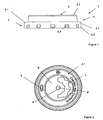
- FIGs 1 and 2 show a side and a plain view of the lid (1).
- This lid comprises an essentially horizontal top wall (2) and a side wall (3), which extends from the rim of the top wall (2).
- the side wall comprises a mounting portion (4) with an annular flange (4.1) and a skirt (4.2).
- the annular flange (4.1) fits on the rim of a container, e.g. a cup to be closed, while the skirt extends below the rim of the container and secures the lid on the container.
- Depressions (4.3) which are optional, improve the attachment of the lid to the container.
- the inventive lid comprises an opening (5) for the removal of the fluid in the container.
- the inventive lid comprises a convexity (9), e.g. a boss or a spigot, for the connection of a slider to the lid.
- the inventive lid comprises a first recess in the center of the lid. Due to this first recession, an annular ring at the outer circumference of the top wall is formed. In this first recession spilled fluid can be captured.
- the lid comprises a second recess, which extends from the first recess. The second recess can be utilized to rotate content indicators (11) as e.g. shown in figure 11 from a remote- into an indicating position.
- the inventive lid comprises a vent hole (8) which is more preferably located on the convexity (9) and even more preferably located in the center of the convexity (9).
- a vent hole can be utilized to discharge a gas from the closed container or to drag air into the closed container.
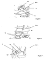
- Figures 3 and 4 show the lid according to figures 1 and 2 in combination with the slider (10). While figure 3 is a top view, figure 4 is a side view of the inventive lid.
- the slider (10) comprises a first end (10.1) and a second end (10.2). By means of the second end, the slider is connected to the lid as will be described in detail later on.
- a multitude of different content indicators (11) are arranged, which are utilized to indicate the consumer the content of the closed container.
- Each content indicator (11) is connected via a hinge (15) to the slider around which it can be rotated from a remote position into an indicating position.
- the content indicators with the letters "B", “C”, “D” are in their remote position while the content indicator with the letter “S” is in the indicating position.
- the content indicators (11) are rotated manually from their remote to their indicating position by, for example, moving the tip of a finger under the respective content indicator (11). This movement is facilitated by the second recess (7).
- the connection between the first end (10.1) and the second end (10.2) of the slider can be utilized by a branding.
- the slider comprises sealing means (12) e.g. a plug, which seals the opening (5) in case that no liquid shall be removed from the container.
- the slider can be, as indicated by the large arrows, rotated clockwise or counter-clockwise, if desired by 360°.
- the first end (10.1) of the slider comprises a handle (13) to facilitate the rotation of the slider.
- the slider is U-shaped at its first end (10.1).
- the sealing means (12) are arranged at the base of the U.
- the U at least partially encompasses the annular ring (22) of the top wall (2).
- the slider may comprise stiffening means (14).
- the outer flank is preferably arrow-shaped, so that it can provide indication about the rotational position of the slider.
- Figures 5 and 6 show details of the design of the slider at its second end (10.2).
- the slider comprises an opening (23), a circle (23).
- the diameter of the circle (23) is slightly smaller than the upper, outer circumference of the convexity (9) which is, shaped as a truncated cone.
- the circle (23) is pushed over the convexity (9).
- one content indicator (11), here the content indicator with the embossment "S" has been rotated from its remote position into its indicating position, in which it is fixed by fastening means (16), here a rebound and/or a groove, into which the circumference of the content indicator is partially inserted.
- Figure 6 shows details of the second end (10.2).
- a groove (16) is arranged into which the circumference of the content indicator (11) is inserted.
- the circumference (17) of the content indicator is preferably at least partially tapered.
- the symbol on each content indicator is located on both surfaces so that it can be seen in the remote and in the indicating position.
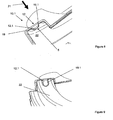
- Figures 7 and 8 show the opening (5) for the removal, e.g. the drinking, of the fluid in the container.
- This opening (5) can be opened and closed by rotating the slider (10) clockwise or anti-clockwise around the fastening means (9).
- the slider comprises at its first end (10.1) sealing means (12), e.g. a sealing plug.
- the opening (5) is arranged in an indentation (19), which is e.g. located in the annular ring (22) of the inventive lid.
- This indentation is e.g. implemented by forming particularly deep drawing. First, the indentation (19) is formed and then the opening (5) is inserted, for example stamped, into this indentation.
- the sealing means (12) are now not, as taught in the state of the art, inserted into hole (5), but seal the hole (5) in a sealing plane (19.1), which lies above the hole (5); i.e. the sealing area (12.1) of the sealing means (12) seal hole (5) in a sealing plane (19.1) which is located on the upper surface (2.1) of the lid (2).
- This embodiment of the present invention has the advantage, that larger production tolerances can be allowed, because the sealing means (12) need not sealingly fit into the opening (5).
- the first end (10.1) of the slider (10) is U-shaped. While the base of the U comprises the sealing means, the flanks of the U encompass the annular ring (22).
- the slider is connected to the lid such, that preferably, the first end (10.1) of the slider is pre-stressed against the lid.
- This preferred embodiment of the present invention improves the sealing between sealing means (12) and the sealing area (19.1).
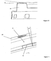
- Figure 9 shows yet another embodiment of the present invention.
- the annular ring (22) is tapered towards the center of the lid by the angle ( ⁇ ). This preferred embodiment of the present invention assures that liquid that is spilled on the ring (22) flows towards the center of the lid.
- FIG 10 shows details of the convexity (9).
- This convexity is in the present case a truncated cone with a draft angle ( ⁇ ).
- ⁇ draft angle
- a vent hole (8) is preferably arranged in the center of the truncated cone.
- Figure 11 shows details of the connection of the slider to the lid.
- the convexity (9) is shaped, preferably deep drawn, as a hollow truncated cone, whose diameter increases with its height. i.e. its extension away from the container.
- the inner diameter of the opening is preferably slightly smaller than the largest outer diameter of the cone, i.e. its outer diameter at its top.
- opening (23) is first pushed over the truncated cone (9), which results in a first form-fit and/or force-fit-connection between the slider and the lid.
- the content indicator (11) is rotated from its remote into its indicating position and fixed with its circumference at the rebound (16).
- the convexity (9) is slightly, preferably elastically, compressed in its height, which results in an enlargement of the diameter of the convexity (9) as indicated by arrow (20).
- the deformation forces the upper part of the convexity at least partially into the rebound or groove (16) which improves the connection between the slider and the lid.
- the vent hole (8) remains open so that the content of the closed container can be still vented via this opening.
Landscapes
- Engineering & Computer Science (AREA)
- Mechanical Engineering (AREA)
- Health & Medical Sciences (AREA)
- General Health & Medical Sciences (AREA)
- Pediatric Medicine (AREA)
- Physics & Mathematics (AREA)
- Mathematical Physics (AREA)
- Theoretical Computer Science (AREA)
- Closures For Containers (AREA)
Description
- The present invention relates to a lid for a container according to the preamble of appended
claim 1. Such a lid is known from WO2009/132049. - A lid is also known from
WO 2006/039044 A2 . However, the lid disclosed in this patent application has hygienic deficiencies and is rather complicated in its design. - It was therefore the objective of the present invention to provide a lid which does not comprise the deficiencies of the state of the art.
- This objective is attained by a lid for a container according to
claim 1. - The present invention relates to a lid for a container holding a flowable substance. Such a container is preferably a cup made e.g. from a paper, cardboard or a plastic material. This container is e.g. filled with a drinkable substance, e.g. tea, coffee, a soft drink or an alcoholic beverage like beer. The flowable substance can also be a food substance like e.g. soup. After the flowable substance has been filled into the container, the container is closed with the inventive lid, which is attached to the upper rim of the container. Therefore, the lid comprises a mounting portion to be attached to the container. Furthermore, the inventive lid comprises an opening to remove, preferably drink, the flowable substance from the container. According to the present invention, this opening can be opened and closed by means of a slider, whereas the opening is opened to remove the liquid from the container and is subsequently closed again. This slider is connected to the lid and rotates around a vertical axis into a closing- and an opening position.
- According to the present invention, this connection is utilized by a form-fit- and/or force-fit-connection between a convexity, i.e. a bulge or a protrusion which extends away from the container, and an opening in the slider. This opening is e.g. pushed on the convexity of the lid.
- The inventive lid is easily produced and very hygienic, because the flowable substance cannot accumulate in the convexity.
- The lid is preferably made from a paper, a plastic and/or a fiber material. The lid is preferably formed from a plain material under the influence of pressure and/or heat, more preferably deep drawn.
- The slider is preferably made from a plastic material and more preferably moulded.
- According to the present invention the convexity is a truncated cone, which is more preferably deep drawn. The diameter of the cross section of the cone preferably increases with its height, i.e. with its extension away from the container, so that the convexity comprises a draft angle. Thus, as soon as the opening, which is a circle with a smaller diameter than the largest outer diameter of the cross section of the cone, is pushed over the truncated cone, it is fixed to the cone in a form-fit- and/or force-fit-connection.
- Furthermore, the slider preferably comprises a content indicator. This content indicator, e.g. one or more letters or one or more numbers or a symbol, indicates the user of the inventive lid which flowable substance is in the container.
- In a preferred embodiment, the inventive lid comprises a multitude of content indicators. Depending on the substance in the container, one of these indicators is brought into an indicating position, to inform the user about the content in the container. Therefore, preferably each content indicator is hingeably connected to the slider and rotatable from a remote into an indicating position, more preferably around a horizontal axis.
- Preferably, each content indicator comprises a first and a second surface, whereas both surfaces comprise the identical information about the content in the container. The surfaces are preferably opposite of each other. In the remote position, the information on the first surface can be seen and in the indicating position, the information on the second surface is visible.
- In a preferred embodiment of the present invention, the slider comprises a fastening means, preferably a rebound, to fix the content indicator in its indicating position. This fastening means assures, that the content indicator remains in its indicating position. The fastening means is preferably a snap-fit-connection. This fastening means is e.g. a rebound and/or a groove, whereas the a rim of the content indicator snaps into this fastening means.
- Preferably, the content indicator deforms the convexity in its indicating position. This compression improves the form-fit- and/or force-fit-connection between the convexity and the slider. More preferred, the content indicator deforms the convexity such, that it extends into the fastening means, preferably the rebound of the lid. This preferred embodiment of the present invention further improves the connection between the lid and the slider.
- Preferably, the slider can be rotated by an angle of 360° around the convexity more preferred in two directions.
- In a preferred or in another embodiment of the present invention, the top wall of the lid comprises an annular ring whose upper surface is tapered, preferably tapered towards the center of the lid. This inventive or preferred embodiment of the present invention assures, that liquid which is spilled on the lid flows towards the center of the lid and not towards the rim of the lid.
- Preferably, the lid comprises a vent hole. This vent hole is preferably arranged on the convexity of the lid, preferably in the center of the convexity of the lid. In a preferred embodiment, this vent hole remains open even after the content indicator has been fixed in its indicating position and/or even after the convexity has been deformed.
- According to yet another inventive or preferred embodiment of the present invention, the opening is located in an indentation. This indentation is preferably arranged in the top wall of the lid. The indentation is preferably produced by forming more preferably deep drawing. This inventive or preferred embodiment of the present invention has the advantage, that fluid in the vicinity of the opening which is captured in the indentation flows back into the container and is not spilled. Preferably, the indentation is arranged in an annular ring of the lid.
- According to yet another preferred or inventive embodiment of the present invention, the opening of the lid is sealed in a sealing plane which lies above the opening i.e. the opening is not sealed at its circumference but in a preferably horizontal plane which is located above the opening, i.e. in a plane which is part of the upper surface of the lid. This inventive or preferred embodiment has the advantage, that a sealing means of the slider, e.g. a plug, does not need to fit exactly into the opening in order to achieve an essentially fluid tight sealing. Thus, larger production tolerances can be allowed without losing a fluid tight sealing. According to another preferred or inventive embodiment of the present invention, the slider comprises sealing means which are pre-stressed against the lid. This preferred embodiment results in an even more fluid tight lid and/or larger production tolerances can be allowed.
- Another embodiment of the present invention is a method for attaching a slider to a lid, whereas an opening of the slider is pushed on a convexity of the lid and that the convexity is then at least partially compressed.
- According to the inventive method, the opening of the slider is first pushed on a convexity of the lid. This results in a form-fit- and/or force-fit-connection which pre-fixes the slider on the lid. Subsequently, the convexity is at least partially compressed. This compression can be an elastic- and/or plastic compression. The compression further improves the connection between the slider and the lid without limiting the rotatability of the slider relative to the lid.
- The disclosure made to the inventive lids also applies to the inventive method and vice versa.
- Preferably, the convexity is compressed by the content indicator, preferably while the content indicator is rotated from its remote to its indicating position.
- The invention is now further explained according to
figures 1-11 . - These explanations do not limit the scope of protection. The explanations are related to all inventions of the present application likewise.
- Figures 1 and 2
- show the inventive lid in two views.
- Figures 3 and 4
- show the lid and the slider.
- Figures 5 and 6
- show the content indicators.
- Figures 7 and 8
- show the sealing of the opening.
- Figure 9
- shows the tapered annular ring.
- Figure 10
- shows details of the convexity.
- Figure 11
- shows the compression of the convexity.
-
Figures 1 and 2 show a side and a plain view of the lid (1). This lid comprises an essentially horizontal top wall (2) and a side wall (3), which extends from the rim of the top wall (2). At its lower end, the side wall comprises a mounting portion (4) with an annular flange (4.1) and a skirt (4.2). In its closed stage, the annular flange (4.1) fits on the rim of a container, e.g. a cup to be closed, while the skirt extends below the rim of the container and secures the lid on the container. Depressions (4.3), which are optional, improve the attachment of the lid to the container. On its upper surface (2.1) the inventive lid comprises an opening (5) for the removal of the fluid in the container. Furthermore, the inventive lid comprises a convexity (9), e.g. a boss or a spigot, for the connection of a slider to the lid. Optionally, the inventive lid comprises a first recess in the center of the lid. Due to this first recession, an annular ring at the outer circumference of the top wall is formed. In this first recession spilled fluid can be captured. Optionally, the lid comprises a second recess, which extends from the first recess. The second recess can be utilized to rotate content indicators (11) as e.g. shown infigure 11 from a remote- into an indicating position. - Preferably, the inventive lid comprises a vent hole (8) which is more preferably located on the convexity (9) and even more preferably located in the center of the convexity (9). A vent hole can be utilized to discharge a gas from the closed container or to drag air into the closed container.
-
Figures 3 and 4 show the lid according tofigures 1 and 2 in combination with the slider (10). Whilefigure 3 is a top view,figure 4 is a side view of the inventive lid. - The slider (10) comprises a first end (10.1) and a second end (10.2). By means of the second end, the slider is connected to the lid as will be described in detail later on. In the vicinity of the second end (10.2) a multitude of different content indicators (11) are arranged, which are utilized to indicate the consumer the content of the closed container. Each content indicator (11) is connected via a hinge (15) to the slider around which it can be rotated from a remote position into an indicating position. The content indicators with the letters "B", "C", "D" are in their remote position while the content indicator with the letter "S" is in the indicating position. The content indicators (11) are rotated manually from their remote to their indicating position by, for example, moving the tip of a finger under the respective content indicator (11). This movement is facilitated by the second recess (7).
- Furthermore, the connection between the first end (10.1) and the second end (10.2) of the slider can be utilized by a branding. At its first end (10.1), the slider comprises sealing means (12) e.g. a plug, which seals the opening (5) in case that no liquid shall be removed from the container. In order to open the opening (5), the slider can be, as indicated by the large arrows, rotated clockwise or counter-clockwise, if desired by 360°. Furthermore, the first end (10.1) of the slider comprises a handle (13) to facilitate the rotation of the slider. As can be particularly seen from
figures 4 and8 , the slider is U-shaped at its first end (10.1). The sealing means (12) are arranged at the base of the U. Together with the two flanks, the U at least partially encompasses the annular ring (22) of the top wall (2). In order to improve the stiffness of the slider, the slider may comprise stiffening means (14). As can be particularly seen fromfigure 4 , the outer flank is preferably arrow-shaped, so that it can provide indication about the rotational position of the slider. -
Figures 5 and 6 show details of the design of the slider at its second end (10.2). At this second end (10.2), the slider comprises an opening (23), a circle (23). The diameter of the circle (23) is slightly smaller than the upper, outer circumference of the convexity (9) which is, shaped as a truncated cone. In order to attach the slider to the lid, the circle (23) is pushed over the convexity (9). Subsequently, as can be particularly seen fromfigure 5 , one content indicator (11), here the content indicator with the embossment "S", has been rotated from its remote position into its indicating position, in which it is fixed by fastening means (16), here a rebound and/or a groove, into which the circumference of the content indicator is partially inserted.Figure 6 shows details of the second end (10.2). As can be clearly seen, at the circumference of the opening (23) a groove (16) is arranged into which the circumference of the content indicator (11) is inserted. In order to facilitate this insertion, the circumference (17) of the content indicator is preferably at least partially tapered. A person skilled in the art understands, that the symbol on each content indicator is located on both surfaces so that it can be seen in the remote and in the indicating position. -
Figures 7 and8 show the opening (5) for the removal, e.g. the drinking, of the fluid in the container. This opening (5) can be opened and closed by rotating the slider (10) clockwise or anti-clockwise around the fastening means (9). In order to close the opening (5), the slider comprises at its first end (10.1) sealing means (12), e.g. a sealing plug. - As can be particularly seen from
figures 8 , the opening (5) is arranged in an indentation (19), which is e.g. located in the annular ring (22) of the inventive lid. This indentation is e.g. implemented by forming particularly deep drawing. First, the indentation (19) is formed and then the opening (5) is inserted, for example stamped, into this indentation. - The sealing means (12) are now not, as taught in the state of the art, inserted into hole (5), but seal the hole (5) in a sealing plane (19.1), which lies above the hole (5); i.e. the sealing area (12.1) of the sealing means (12) seal hole (5) in a sealing plane (19.1) which is located on the upper surface (2.1) of the lid (2). This embodiment of the present invention has the advantage, that larger production tolerances can be allowed, because the sealing means (12) need not sealingly fit into the opening (5). As can be also seen from
figures 8 , the first end (10.1) of the slider (10) is U-shaped. While the base of the U comprises the sealing means, the flanks of the U encompass the annular ring (22). As indicated by arrow (21), the slider is connected to the lid such, that preferably, the first end (10.1) of the slider is pre-stressed against the lid. This preferred embodiment of the present invention improves the sealing between sealing means (12) and the sealing area (19.1). -
Figure 9 shows yet another embodiment of the present invention. - In the present case, the annular ring (22) is tapered towards the center of the lid by the angle (α). This preferred embodiment of the present invention assures that liquid that is spilled on the ring (22) flows towards the center of the lid.
-
Figure 10 shows details of the convexity (9). This convexity is in the present case a truncated cone with a draft angle (β). In the center of the truncated cone a vent hole (8) is preferably arranged. -
Figure 11 shows details of the connection of the slider to the lid. As can be seen, the convexity (9) is shaped, preferably deep drawn, as a hollow truncated cone, whose diameter increases with its height. i.e. its extension away from the container. The inner diameter of the opening is preferably slightly smaller than the largest outer diameter of the cone, i.e. its outer diameter at its top. In order to connect the slider with the lid, opening (23) is first pushed over the truncated cone (9), which results in a first form-fit and/or force-fit-connection between the slider and the lid. Subsequently, as indicated by arrow (18), the content indicator (11) is rotated from its remote into its indicating position and fixed with its circumference at the rebound (16). During this rotation, the convexity (9) is slightly, preferably elastically, compressed in its height, which results in an enlargement of the diameter of the convexity (9) as indicated by arrow (20). The deformation forces the upper part of the convexity at least partially into the rebound or groove (16) which improves the connection between the slider and the lid. Even though, the content indicator (11) has been rotated into its indicating position, the vent hole (8) remains open so that the content of the closed container can be still vented via this opening. -
- 1
- Lid
- 2
- Top wall
- 2.1
- Upper surface
- 3
- Side wall
- 4
- Mounting portion
- 4.1
- Annular flange
- 4.2
- Skirt
- 4.3
- Depression
- 5
- Opening, fluid removal
- 6
- First recess
- 7
- Second recess
- 8
- Vent hole
- 9
- Convexity, boss, spigot
- 10
- Slider
- 10.1
- First end of the slider
- 10.2
- Second end of the slider
- 11
- Content indicator
- 12
- Sealing means, plug
- 12.1
- Sealing area
- 13
- Handle
- 14
- Stiffening means
- 15
- Hinge, score
- 16
- Fastening means for the
content indicator 11, rebound, groove - 17
- Circumference of the content indicator, Taper
- 18
- Movement of the content indicator
- 19
- Indentation
- 19.1
- Sealing area of the indentation
- 20
- Clipping action
- 21
- Pretension force
- 22
- Circular ring
- 23
- Opening, circle
- α
- Taper angel of the top wall of the annular ring
- β
- Draft angle of the convexity
Claims (9)
- A lid (1) for a container holding a flowable substance, which comprises a top wall (2), a side wall (3) and a mounting portion (4) to be attached to the container and an opening (5) to remove the flowable substance from the container, whereas the opening (5) is opened and closed by means of a slider (10), which rotates around a vertical axis and which is connected to the lid by a convexity (9) in the lid and an opening (23) in the slider (10), wherein the connection is a form-fit and/or force-fit-connection and wherein the slider has a first end (10.1) and a second end (10.2), wherein the slider is connected to the lid (1) at the second end (10.2), wherein, the top wall (2) comprises an annular ring (22), in which the opening (5) is provided and wherein the slider is U-shaped at its first end (10.1) and sealing means (12) is arranged at the base of the U, which seals the opening (5) in the lid and wherein the U at least partially encompasses the annular ring, characterized in that the convexity is a truncated cone whose diameter increases with its height and in that the opening (23) in the slider (10) is a circle with a smaller diameter than the largest outer diameter of the cross section of the truncated cone.
- A lid (1) according to claim 1, characterized in, that the slider comprises a content indicator (11).
- A lid (1) according to claim 2, characterized in, that the content indicator (11) is hingably connected to the slider (10) and rotatable from a remote into an indicating position.
- A lid (1) according to claims 2 or 3, characterized in, that the slider (10) comprises a fastening means (16), preferably a rebound (16), to fix the content indicator (11) in its indicating position.
- A lid (1) according to claims 3 or 4, characterized in, that the content indicator deforms the convexity (9) in the indicating position, so that it preferably extends into the rebound (16).
- A lid (1) according to one of the preceding claims or the preamble of claim 1, characterized in, that upper surface of the top wall (2) of the lid (1) is tapered.
- A lid (1) according to one of the preceding claims, characterized in, that the opening (5) in the lid (1) is located in an indentation (19).
- A lid (1) according to one of the preceding claims, characterized in, that the opening (5) is sealed in a sealing plane (19.1) above the opening.
- A lid (1) according to one of the preceding claims, characterized in, that the sealing means (12) is pre-stressed against the lid.
Priority Applications (4)
| Application Number | Priority Date | Filing Date | Title |
|---|---|---|---|
| PL11008876.2T PL2592014T3 (en) | 2011-11-08 | 2011-11-08 | Lid for a container with a slider |
| EP11008876.2A EP2592014B1 (en) | 2011-11-08 | 2011-11-08 | Lid for a container with a slider |
| ES11008876.2T ES2579234T3 (en) | 2011-11-08 | 2011-11-08 | Lid for a container with a sliding element |
| US13/671,056 US8608000B2 (en) | 2011-11-08 | 2012-11-07 | Lid for a container with a slider |
Applications Claiming Priority (1)
| Application Number | Priority Date | Filing Date | Title |
|---|---|---|---|
| EP11008876.2A EP2592014B1 (en) | 2011-11-08 | 2011-11-08 | Lid for a container with a slider |
Publications (2)
| Publication Number | Publication Date |
|---|---|
| EP2592014A1 EP2592014A1 (en) | 2013-05-15 |
| EP2592014B1 true EP2592014B1 (en) | 2016-03-30 |
Family
ID=45346143
Family Applications (1)
| Application Number | Title | Priority Date | Filing Date |
|---|---|---|---|
| EP11008876.2A Active EP2592014B1 (en) | 2011-11-08 | 2011-11-08 | Lid for a container with a slider |
Country Status (4)
| Country | Link |
|---|---|
| US (1) | US8608000B2 (en) |
| EP (1) | EP2592014B1 (en) |
| ES (1) | ES2579234T3 (en) |
| PL (1) | PL2592014T3 (en) |
Families Citing this family (3)
| Publication number | Priority date | Publication date | Assignee | Title |
|---|---|---|---|---|
| US9624011B2 (en) * | 2014-03-05 | 2017-04-18 | uVu Technologies, LLC | Lid with rotatable closure tab |
| DE102014219272A1 (en) * | 2014-09-24 | 2016-03-24 | Ptm Packaging Tools Machinery Pte. Ltd. | Lid for a beverage cup, cup assembly and method for making a lid |
| WO2017127056A1 (en) * | 2016-01-19 | 2017-07-27 | Newman John Anthoney | Lid for a drink cup |
Citations (1)
| Publication number | Priority date | Publication date | Assignee | Title |
|---|---|---|---|---|
| EP0439268A2 (en) * | 1990-01-23 | 1991-07-31 | Ferry Pickering (Sales) Limited | Tamper-evident drum containers |
Family Cites Families (13)
| Publication number | Priority date | Publication date | Assignee | Title |
|---|---|---|---|---|
| US2791846A (en) * | 1953-08-27 | 1957-05-14 | Jr Eric Muelberger | Combined bottle closure and order indicating device |
| DE7540150U (en) * | 1975-12-17 | 1976-05-06 | Boenecke & Co Kg Vapac | Child-proof rotary slide closure for bottles and similar containers |
| US4183443A (en) * | 1978-08-25 | 1980-01-15 | Billitzer Edward P | Reusable cup cover |
| US4274563A (en) * | 1979-07-30 | 1981-06-23 | Weatherchem Corporation | Plastic end closure for hermetically sealed container |
| US5082134A (en) * | 1990-11-28 | 1992-01-21 | Ramsey Douglas P | Self-sealing closure |
| US5148936A (en) * | 1991-04-05 | 1992-09-22 | Aladdin Synergetics, Incorporated | Container closure arrangement |
| US5294014A (en) * | 1992-10-16 | 1994-03-15 | Aladdin Synergetics, Inc. | Container closure arrangement |
| US6220470B1 (en) * | 1997-10-20 | 2001-04-24 | American National Can Company | Resealable closure for open end of container |
| US6352166B1 (en) * | 1999-02-10 | 2002-03-05 | William Industries, Inc. | Self-closing lid apparatus |
| US7731047B2 (en) * | 2001-08-06 | 2010-06-08 | Solo Cup Operating Corporation | Reclosable container lid with sliding element |
| WO2003042058A2 (en) * | 2001-11-13 | 2003-05-22 | Dart Container Corporation | Recloseable lid with closure plug |
| US7721911B2 (en) * | 2006-12-18 | 2010-05-25 | Bob Chou | Rotating type cup lid |
| US20110068113A1 (en) * | 2008-04-21 | 2011-03-24 | Stanley Kim | Sanitary Cup Lids |
-
2011
- 2011-11-08 ES ES11008876.2T patent/ES2579234T3/en active Active
- 2011-11-08 EP EP11008876.2A patent/EP2592014B1/en active Active
- 2011-11-08 PL PL11008876.2T patent/PL2592014T3/en unknown
-
2012
- 2012-11-07 US US13/671,056 patent/US8608000B2/en active Active
Patent Citations (1)
| Publication number | Priority date | Publication date | Assignee | Title |
|---|---|---|---|---|
| EP0439268A2 (en) * | 1990-01-23 | 1991-07-31 | Ferry Pickering (Sales) Limited | Tamper-evident drum containers |
Also Published As
| Publication number | Publication date |
|---|---|
| US8608000B2 (en) | 2013-12-17 |
| EP2592014A1 (en) | 2013-05-15 |
| PL2592014T3 (en) | 2016-10-31 |
| US20130112699A1 (en) | 2013-05-09 |
| ES2579234T3 (en) | 2016-08-08 |
Similar Documents
| Publication | Publication Date | Title |
|---|---|---|
| US7845525B2 (en) | Carbonated drink closure and dispensing device | |
| EP1874645A1 (en) | Asymmetric lid for use with an open-top container | |
| EP2592014B1 (en) | Lid for a container with a slider | |
| WO2016036919A1 (en) | Receptacle closure | |
| JP2010537899A (en) | Closures for bottles and assembly of such closures and bottles | |
| CN102414087A (en) | Reclosable closure and beverage can and beverage carton | |
| EP3967621A1 (en) | Toy cap | |
| US20110163135A1 (en) | Multi-piece closure with hinged lid | |
| JP6346792B2 (en) | Beverage container provided with a stopper and a stopper | |
| US20100078404A1 (en) | Cap lifter for plugging cap, plugging assembly including a cap and said cap lifter | |
| NZ589721A (en) | A container including a lid with improved fluid dispensing and collecting rim arrangement | |
| AU2014375225B2 (en) | Topper for a container | |
| JP2018502791A (en) | Non-metallic and hybrid crown with opener assembly | |
| JP5181335B2 (en) | Beverage container | |
| CN213736502U (en) | Bottle cap assembly with titanium sleeve and cap body | |
| KR20050059718A (en) | Container and cap having same | |
| JP2019529266A (en) | Cap for food packaging container | |
| CN101734400A (en) | Pull lid structure of pop-top can | |
| CN201026119Y (en) | Mixing cup with split type sealing cap | |
| CN216270846U (en) | Anti-fake bottle cap | |
| CN218318312U (en) | Rotary dual-purpose cup cover and drink cup adopting same | |
| CN101479163B (en) | Can | |
| US10737831B2 (en) | Method and apparatus for sealing an opened beverage container | |
| KR200412198Y1 (en) | Ring cap | |
| RU87408U1 (en) | ALUMINUM CONTAINER FOR LIQUIDS WITH A CLOSING KEY |
Legal Events
| Date | Code | Title | Description |
|---|---|---|---|
| PUAI | Public reference made under article 153(3) epc to a published international application that has entered the european phase |
Free format text: ORIGINAL CODE: 0009012 |
|
| AK | Designated contracting states |
Kind code of ref document: A1 Designated state(s): AL AT BE BG CH CY CZ DE DK EE ES FI FR GB GR HR HU IE IS IT LI LT LU LV MC MK MT NL NO PL PT RO RS SE SI SK SM TR |
|
| AX | Request for extension of the european patent |
Extension state: BA ME |
|
| 17P | Request for examination filed |
Effective date: 20131111 |
|
| RBV | Designated contracting states (corrected) |
Designated state(s): AL AT BE BG CH CY CZ DE DK EE ES FI FR GB GR HR HU IE IS IT LI LT LU LV MC MK MT NL NO PL PT RO RS SE SI SK SM TR |
|
| 17Q | First examination report despatched |
Effective date: 20140224 |
|
| GRAP | Despatch of communication of intention to grant a patent |
Free format text: ORIGINAL CODE: EPIDOSNIGR1 |
|
| INTG | Intention to grant announced |
Effective date: 20151016 |
|
| GRAS | Grant fee paid |
Free format text: ORIGINAL CODE: EPIDOSNIGR3 |
|
| GRAA | (expected) grant |
Free format text: ORIGINAL CODE: 0009210 |
|
| AK | Designated contracting states |
Kind code of ref document: B1 Designated state(s): AL AT BE BG CH CY CZ DE DK EE ES FI FR GB GR HR HU IE IS IT LI LT LU LV MC MK MT NL NO PL PT RO RS SE SI SK SM TR |
|
| REG | Reference to a national code |
Ref country code: GB Ref legal event code: FG4D |
|
| REG | Reference to a national code |
Ref country code: CH Ref legal event code: EP |
|
| REG | Reference to a national code |
Ref country code: AT Ref legal event code: REF Ref document number: 785104 Country of ref document: AT Kind code of ref document: T Effective date: 20160415 |
|
| REG | Reference to a national code |
Ref country code: IE Ref legal event code: FG4D |
|
| REG | Reference to a national code |
Ref country code: DE Ref legal event code: R096 Ref document number: 602011024492 Country of ref document: DE |
|
| RAP2 | Party data changed (patent owner data changed or rights of a patent transferred) |
Owner name: HUHTAMAEKI OYJ |
|
| REG | Reference to a national code |
Ref country code: NO Ref legal event code: T2 Effective date: 20160330 |
|
| REG | Reference to a national code |
Ref country code: SE Ref legal event code: TRGR |
|
| REG | Reference to a national code |
Ref country code: LT Ref legal event code: MG4D |
|
| PG25 | Lapsed in a contracting state [announced via postgrant information from national office to epo] |
Ref country code: GR Free format text: LAPSE BECAUSE OF FAILURE TO SUBMIT A TRANSLATION OF THE DESCRIPTION OR TO PAY THE FEE WITHIN THE PRESCRIBED TIME-LIMIT Effective date: 20160701 Ref country code: HR Free format text: LAPSE BECAUSE OF FAILURE TO SUBMIT A TRANSLATION OF THE DESCRIPTION OR TO PAY THE FEE WITHIN THE PRESCRIBED TIME-LIMIT Effective date: 20160330 |
|
| REG | Reference to a national code |
Ref country code: NL Ref legal event code: MP Effective date: 20160330 |
|
| REG | Reference to a national code |
Ref country code: ES Ref legal event code: FG2A Ref document number: 2579234 Country of ref document: ES Kind code of ref document: T3 Effective date: 20160808 |
|
| REG | Reference to a national code |
Ref country code: EE Ref legal event code: FG4A Ref document number: E012041 Country of ref document: EE Effective date: 20160622 Ref country code: AT Ref legal event code: MK05 Ref document number: 785104 Country of ref document: AT Kind code of ref document: T Effective date: 20160330 |
|
| PG25 | Lapsed in a contracting state [announced via postgrant information from national office to epo] |
Ref country code: LT Free format text: LAPSE BECAUSE OF FAILURE TO SUBMIT A TRANSLATION OF THE DESCRIPTION OR TO PAY THE FEE WITHIN THE PRESCRIBED TIME-LIMIT Effective date: 20160330 Ref country code: RS Free format text: LAPSE BECAUSE OF FAILURE TO SUBMIT A TRANSLATION OF THE DESCRIPTION OR TO PAY THE FEE WITHIN THE PRESCRIBED TIME-LIMIT Effective date: 20160330 Ref country code: LV Free format text: LAPSE BECAUSE OF FAILURE TO SUBMIT A TRANSLATION OF THE DESCRIPTION OR TO PAY THE FEE WITHIN THE PRESCRIBED TIME-LIMIT Effective date: 20160330 |
|
| PG25 | Lapsed in a contracting state [announced via postgrant information from national office to epo] |
Ref country code: NL Free format text: LAPSE BECAUSE OF FAILURE TO SUBMIT A TRANSLATION OF THE DESCRIPTION OR TO PAY THE FEE WITHIN THE PRESCRIBED TIME-LIMIT Effective date: 20160330 |
|
| PG25 | Lapsed in a contracting state [announced via postgrant information from national office to epo] |
Ref country code: IS Free format text: LAPSE BECAUSE OF FAILURE TO SUBMIT A TRANSLATION OF THE DESCRIPTION OR TO PAY THE FEE WITHIN THE PRESCRIBED TIME-LIMIT Effective date: 20160730 |
|
| REG | Reference to a national code |
Ref country code: FR Ref legal event code: PLFP Year of fee payment: 6 |
|
| PG25 | Lapsed in a contracting state [announced via postgrant information from national office to epo] |
Ref country code: SM Free format text: LAPSE BECAUSE OF FAILURE TO SUBMIT A TRANSLATION OF THE DESCRIPTION OR TO PAY THE FEE WITHIN THE PRESCRIBED TIME-LIMIT Effective date: 20160330 Ref country code: RO Free format text: LAPSE BECAUSE OF FAILURE TO SUBMIT A TRANSLATION OF THE DESCRIPTION OR TO PAY THE FEE WITHIN THE PRESCRIBED TIME-LIMIT Effective date: 20160330 Ref country code: AT Free format text: LAPSE BECAUSE OF FAILURE TO SUBMIT A TRANSLATION OF THE DESCRIPTION OR TO PAY THE FEE WITHIN THE PRESCRIBED TIME-LIMIT Effective date: 20160330 Ref country code: PT Free format text: LAPSE BECAUSE OF FAILURE TO SUBMIT A TRANSLATION OF THE DESCRIPTION OR TO PAY THE FEE WITHIN THE PRESCRIBED TIME-LIMIT Effective date: 20160801 Ref country code: CZ Free format text: LAPSE BECAUSE OF FAILURE TO SUBMIT A TRANSLATION OF THE DESCRIPTION OR TO PAY THE FEE WITHIN THE PRESCRIBED TIME-LIMIT Effective date: 20160330 Ref country code: SK Free format text: LAPSE BECAUSE OF FAILURE TO SUBMIT A TRANSLATION OF THE DESCRIPTION OR TO PAY THE FEE WITHIN THE PRESCRIBED TIME-LIMIT Effective date: 20160330 |
|
| PG25 | Lapsed in a contracting state [announced via postgrant information from national office to epo] |
Ref country code: BE Free format text: LAPSE BECAUSE OF FAILURE TO SUBMIT A TRANSLATION OF THE DESCRIPTION OR TO PAY THE FEE WITHIN THE PRESCRIBED TIME-LIMIT Effective date: 20160330 Ref country code: IT Free format text: LAPSE BECAUSE OF FAILURE TO SUBMIT A TRANSLATION OF THE DESCRIPTION OR TO PAY THE FEE WITHIN THE PRESCRIBED TIME-LIMIT Effective date: 20160330 |
|
| REG | Reference to a national code |
Ref country code: DE Ref legal event code: R097 Ref document number: 602011024492 Country of ref document: DE |
|
| PG25 | Lapsed in a contracting state [announced via postgrant information from national office to epo] |
Ref country code: DK Free format text: LAPSE BECAUSE OF FAILURE TO SUBMIT A TRANSLATION OF THE DESCRIPTION OR TO PAY THE FEE WITHIN THE PRESCRIBED TIME-LIMIT Effective date: 20160330 |
|
| PLBE | No opposition filed within time limit |
Free format text: ORIGINAL CODE: 0009261 |
|
| STAA | Information on the status of an ep patent application or granted ep patent |
Free format text: STATUS: NO OPPOSITION FILED WITHIN TIME LIMIT |
|
| 26N | No opposition filed |
Effective date: 20170103 |
|
| PG25 | Lapsed in a contracting state [announced via postgrant information from national office to epo] |
Ref country code: SI Free format text: LAPSE BECAUSE OF FAILURE TO SUBMIT A TRANSLATION OF THE DESCRIPTION OR TO PAY THE FEE WITHIN THE PRESCRIBED TIME-LIMIT Effective date: 20160330 |
|
| REG | Reference to a national code |
Ref country code: EE Ref legal event code: MM4A Ref document number: E012041 Country of ref document: EE Effective date: 20161130 |
|
| REG | Reference to a national code |
Ref country code: NO Ref legal event code: MMEP |
|
| REG | Reference to a national code |
Ref country code: CH Ref legal event code: PL |
|
| PG25 | Lapsed in a contracting state [announced via postgrant information from national office to epo] |
Ref country code: LI Free format text: LAPSE BECAUSE OF NON-PAYMENT OF DUE FEES Effective date: 20161130 Ref country code: EE Free format text: LAPSE BECAUSE OF NON-PAYMENT OF DUE FEES Effective date: 20161130 Ref country code: CH Free format text: LAPSE BECAUSE OF NON-PAYMENT OF DUE FEES Effective date: 20161130 Ref country code: NO Free format text: LAPSE BECAUSE OF NON-PAYMENT OF DUE FEES Effective date: 20161130 |
|
| REG | Reference to a national code |
Ref country code: IE Ref legal event code: MM4A |
|
| PG25 | Lapsed in a contracting state [announced via postgrant information from national office to epo] |
Ref country code: LU Free format text: LAPSE BECAUSE OF NON-PAYMENT OF DUE FEES Effective date: 20161130 |
|
| REG | Reference to a national code |
Ref country code: FR Ref legal event code: PLFP Year of fee payment: 7 |
|
| PG25 | Lapsed in a contracting state [announced via postgrant information from national office to epo] |
Ref country code: IE Free format text: LAPSE BECAUSE OF NON-PAYMENT OF DUE FEES Effective date: 20161108 |
|
| PGFP | Annual fee paid to national office [announced via postgrant information from national office to epo] |
Ref country code: PL Payment date: 20171031 Year of fee payment: 7 |
|
| PG25 | Lapsed in a contracting state [announced via postgrant information from national office to epo] |
Ref country code: HU Free format text: LAPSE BECAUSE OF FAILURE TO SUBMIT A TRANSLATION OF THE DESCRIPTION OR TO PAY THE FEE WITHIN THE PRESCRIBED TIME-LIMIT; INVALID AB INITIO Effective date: 20111108 Ref country code: CY Free format text: LAPSE BECAUSE OF FAILURE TO SUBMIT A TRANSLATION OF THE DESCRIPTION OR TO PAY THE FEE WITHIN THE PRESCRIBED TIME-LIMIT Effective date: 20160330 |
|
| PG25 | Lapsed in a contracting state [announced via postgrant information from national office to epo] |
Ref country code: MC Free format text: LAPSE BECAUSE OF FAILURE TO SUBMIT A TRANSLATION OF THE DESCRIPTION OR TO PAY THE FEE WITHIN THE PRESCRIBED TIME-LIMIT Effective date: 20160330 Ref country code: MK Free format text: LAPSE BECAUSE OF FAILURE TO SUBMIT A TRANSLATION OF THE DESCRIPTION OR TO PAY THE FEE WITHIN THE PRESCRIBED TIME-LIMIT Effective date: 20160330 Ref country code: TR Free format text: LAPSE BECAUSE OF FAILURE TO SUBMIT A TRANSLATION OF THE DESCRIPTION OR TO PAY THE FEE WITHIN THE PRESCRIBED TIME-LIMIT Effective date: 20160330 |
|
| PG25 | Lapsed in a contracting state [announced via postgrant information from national office to epo] |
Ref country code: BG Free format text: LAPSE BECAUSE OF FAILURE TO SUBMIT A TRANSLATION OF THE DESCRIPTION OR TO PAY THE FEE WITHIN THE PRESCRIBED TIME-LIMIT Effective date: 20160330 |
|
| PG25 | Lapsed in a contracting state [announced via postgrant information from national office to epo] |
Ref country code: MT Free format text: LAPSE BECAUSE OF NON-PAYMENT OF DUE FEES Effective date: 20161108 |
|
| PG25 | Lapsed in a contracting state [announced via postgrant information from national office to epo] |
Ref country code: AL Free format text: LAPSE BECAUSE OF FAILURE TO SUBMIT A TRANSLATION OF THE DESCRIPTION OR TO PAY THE FEE WITHIN THE PRESCRIBED TIME-LIMIT Effective date: 20160330 |
|
| PGFP | Annual fee paid to national office [announced via postgrant information from national office to epo] |
Ref country code: IE Payment date: 20181121 Year of fee payment: 8 Ref country code: SE Payment date: 20181126 Year of fee payment: 8 |
|
| PG25 | Lapsed in a contracting state [announced via postgrant information from national office to epo] |
Ref country code: PL Free format text: LAPSE BECAUSE OF NON-PAYMENT OF DUE FEES Effective date: 20181108 |
|
| REG | Reference to a national code |
Ref country code: FI Ref legal event code: MAE |
|
| REG | Reference to a national code |
Ref country code: SE Ref legal event code: EUG |
|
| PG25 | Lapsed in a contracting state [announced via postgrant information from national office to epo] |
Ref country code: FI Free format text: LAPSE BECAUSE OF NON-PAYMENT OF DUE FEES Effective date: 20191108 |
|
| PG25 | Lapsed in a contracting state [announced via postgrant information from national office to epo] |
Ref country code: SE Free format text: LAPSE BECAUSE OF NON-PAYMENT OF DUE FEES Effective date: 20191109 |
|
| PG25 | Lapsed in a contracting state [announced via postgrant information from national office to epo] |
Ref country code: ES Free format text: LAPSE BECAUSE OF NON-PAYMENT OF DUE FEES Effective date: 20191109 |
|
| PGFP | Annual fee paid to national office [announced via postgrant information from national office to epo] |
Ref country code: FR Payment date: 20211119 Year of fee payment: 11 Ref country code: DE Payment date: 20211122 Year of fee payment: 11 |
|
| REG | Reference to a national code |
Ref country code: DE Ref legal event code: R119 Ref document number: 602011024492 Country of ref document: DE |
|
| PG25 | Lapsed in a contracting state [announced via postgrant information from national office to epo] |
Ref country code: DE Free format text: LAPSE BECAUSE OF NON-PAYMENT OF DUE FEES Effective date: 20230601 |
|
| PG25 | Lapsed in a contracting state [announced via postgrant information from national office to epo] |
Ref country code: FR Free format text: LAPSE BECAUSE OF NON-PAYMENT OF DUE FEES Effective date: 20221130 |
|
| PGFP | Annual fee paid to national office [announced via postgrant information from national office to epo] |
Ref country code: GB Payment date: 20231123 Year of fee payment: 13 |