EP2591987A1 - Vehicle hood structure - Google Patents
Vehicle hood structure Download PDFInfo
- Publication number
- EP2591987A1 EP2591987A1 EP10854435.4A EP10854435A EP2591987A1 EP 2591987 A1 EP2591987 A1 EP 2591987A1 EP 10854435 A EP10854435 A EP 10854435A EP 2591987 A1 EP2591987 A1 EP 2591987A1
- Authority
- EP
- European Patent Office
- Prior art keywords
- hood
- section
- inner panel
- wave shaped
- outer panel
- Prior art date
- Legal status (The legal status is an assumption and is not a legal conclusion. Google has not performed a legal analysis and makes no representation as to the accuracy of the status listed.)
- Granted
Links
- 239000011324 bead Substances 0.000 abstract description 30
- 238000010521 absorption reaction Methods 0.000 abstract description 14
- 230000003116 impacting effect Effects 0.000 abstract description 14
- 230000000052 comparative effect Effects 0.000 description 19
- 230000002787 reinforcement Effects 0.000 description 16
- 238000005452 bending Methods 0.000 description 9
- 230000001133 acceleration Effects 0.000 description 8
- 150000001875 compounds Chemical class 0.000 description 7
- 238000010409 ironing Methods 0.000 description 6
- 230000000694 effects Effects 0.000 description 5
- 229910000838 Al alloy Inorganic materials 0.000 description 3
- 238000006243 chemical reaction Methods 0.000 description 3
- 229910052751 metal Inorganic materials 0.000 description 3
- 239000002184 metal Substances 0.000 description 3
- 239000013521 mastic Substances 0.000 description 2
- 230000002093 peripheral effect Effects 0.000 description 2
- 239000000853 adhesive Substances 0.000 description 1
- 230000001070 adhesive effect Effects 0.000 description 1
- 238000009957 hemming Methods 0.000 description 1
- 230000000750 progressive effect Effects 0.000 description 1
- 230000000717 retained effect Effects 0.000 description 1
- 239000011800 void material Substances 0.000 description 1
Images



Classifications
-
- B—PERFORMING OPERATIONS; TRANSPORTING
- B62—LAND VEHICLES FOR TRAVELLING OTHERWISE THAN ON RAILS
- B62D—MOTOR VEHICLES; TRAILERS
- B62D25/00—Superstructure or monocoque structure sub-units; Parts or details thereof not otherwise provided for
- B62D25/08—Front or rear portions
- B62D25/10—Bonnets or lids, e.g. for trucks, tractors, busses, work vehicles
-
- B—PERFORMING OPERATIONS; TRANSPORTING
- B60—VEHICLES IN GENERAL
- B60R—VEHICLES, VEHICLE FITTINGS, OR VEHICLE PARTS, NOT OTHERWISE PROVIDED FOR
- B60R21/00—Arrangements or fittings on vehicles for protecting or preventing injuries to occupants or pedestrians in case of accidents or other traffic risks
- B60R21/34—Protecting non-occupants of a vehicle, e.g. pedestrians
-
- B—PERFORMING OPERATIONS; TRANSPORTING
- B62—LAND VEHICLES FOR TRAVELLING OTHERWISE THAN ON RAILS
- B62D—MOTOR VEHICLES; TRAILERS
- B62D25/00—Superstructure or monocoque structure sub-units; Parts or details thereof not otherwise provided for
- B62D25/08—Front or rear portions
- B62D25/10—Bonnets or lids, e.g. for trucks, tractors, busses, work vehicles
- B62D25/105—Bonnets or lids, e.g. for trucks, tractors, busses, work vehicles for motor cars
-
- B—PERFORMING OPERATIONS; TRANSPORTING
- B60—VEHICLES IN GENERAL
- B60R—VEHICLES, VEHICLE FITTINGS, OR VEHICLE PARTS, NOT OTHERWISE PROVIDED FOR
- B60R21/00—Arrangements or fittings on vehicles for protecting or preventing injuries to occupants or pedestrians in case of accidents or other traffic risks
- B60R21/34—Protecting non-occupants of a vehicle, e.g. pedestrians
- B60R2021/343—Protecting non-occupants of a vehicle, e.g. pedestrians using deformable body panel, bodywork or components
Definitions
- the present invention relates to a vehicle hood structure that is applied to a vehicle such as an automobile.
- Known vehicle hood structures include structures wherein a hood outer panel and a hood inner panel are coupled together. From the perspective of pedestrian protection, in such structures the hood inner panel may include plural beads arranged alongside each other with length directions oriented in the vehicle body front-rear direction, forming a wave shaped profile (see for example Patent Document 1).
- primary impact a high proportion of the load acting on the impacting body prior to the impacting body impacting a rigid object at the bottom side of the hood inner panel
- secondary impact is load due to the inertia of the hood panel.
- an object of the present invention is to obtain a vehicle hood structure capable of improving impact absorption ability prior to secondary impact when an impacting body impacts the hood.
- a vehicle hood structure of a first aspect of the present invention includes a hood outer panel that configures an outer panel of a hood, and a hood inner panel that is disposed at a hood bottom side of the hood outer panel and that is coupled to the hood outer panel to configure an inner panel of the hood.
- the hood inner panel includes: a wave shaped section that is provided at a central region of the hood inner panel and that includes protruding portions oriented with a length direction in a hood front-rear direction to give protruding shapes on the hood outer panel side, and indented portions oriented with a length direction in the hood front-rear direction to give indented shapes on the hood outer panel side, the protruding portions and the indented portions provided alternately to form a wave shaped profile, and with hood front-rear direction front end portions of the protruding portions arranged in a line in a hood plan view; a front wall section that is provided to the hood inner panel further to a hood front side than the wave shaped section, that is inclined towards the hood bottom side on progression towards a hood front, and that is formed substantially along the hood width direction; and a ledge section that is formed substantially along the hood width direction and that connects together the wave shaped section and the front wall section in the hood inner
- the hood inner panel is disposed at the hood bottom side of the hood outer panel and coupled to the hood outer panel, and the hood inner panel is formed with the wave shaped section at a central portion thereof.
- the wave shaped section is alternately provided with the protruding portions and the indented portions respectively orientated with length directions in the hood front-rear direction to give a wave shaped profile.
- the wave shaped section accordingly has a comparatively high rigidity with respect to impact load.
- the front end portions of the protruding portions of the wave shaped section are arranged in a line in hood plan view, and the front wall section is provided further to the hood front side than the wave shaped section, inclined towards the hood bottom side on progression towards the hood front, and formed substantially along the hood width direction. Accordingly, when an impacting body impacts the hood and load is input to the wave shaped section, bending deformation towards the hood bottom side occurs in the ledge section that has a lower rigidity than the wave shaped section. The front wall section deforms so as to bulge out diagonally towards a hood front upper side accompanying the deformation of the ledge section.
- the hood outer panel displaces towards the hood bottom side due to the impact load, causing the hood outer panel to (directly or indirectly) contact a rear end portion side of the front wall section, after which the contact position of the hood outer panel and the front wall section gradually changes towards the hood front side. Accordingly, the rear end portion side of the front wall section undergoes bending deformation such that a plastic deformation location deforms so as to move progressively and continuously towards the hood front side (ironing deformation). Energy expended in plastic deformation is absorbed, thereby improving impact absorption ability prior to secondary impact.
- a second aspect of the present invention is the vehicle hood structure of the first aspect wherein a ridge line configuring the location of connection between the ledge section and the front wall section is formed along the hood width direction in a straight line shape in a hood plan view.
- the ridge line configuring the location of connection between the ledge section and the front wall section is formed along the hood width direction in a straight line shape in hood plan view.
- the plastic deformation location of the front wall section therefore becomes a straight line shaped fold-bend deformation portion along the hood width direction and moves stably towards the hood front side. Namely, the front wall section deforms with a stable deformation mode.
- the vehicle hood structure according to the first aspect of the present invention exhibits the excellent advantageous effect of enabling impact absorption ability prior to secondary impact when an impacting body impacts the hood to be improved.
- the vehicle hood structure according to the second aspect of the present invention exhibits the excellent advantageous effect of increasing the precision of impact absorption ability prior to secondary impact when an impacting body impacts the hood.
- a vehicle hood structure according to a first exemplary embodiment of the present invention, with reference to Fig. 1 to Fig. 10 .
- the arrow FR indicates the vehicle front side
- the arrow UP indicates the vehicle top side
- the arrow W indicates the vehicle width direction as appropriate.
- the hood front-rear direction is the same direction as the vehicle front-rear direction
- the hood top-bottom direction is the same direction as the vehicle top-bottom direction
- the hood width direction is the same direction as the vehicle width direction.
- Fig. 1 is a plan view illustrating a hood 14 applied to a vehicle hood structure according to the present exemplary embodiment with elements such as a hood outer panel 16 (refer to the double-dash intermittent line) shown in a see-through state.
- Fig. 2 is an enlarged cross-section taken along line 2-2 in Fig. 1 .
- a vehicle front section 10A of an automobile is provided with a hood (engine hood) 14 that covers an engine compartment 12 such that the engine compartement 12 can be opened and closed.
- a rigid body 12A such as a power unit is installed inside the engine compartment 12 covered by the hood 14.
- the hood 14 is made out of metal (out of an aluminum alloy in the present exemplary embodiment, by way of an example). As shown in Fig. 1 , the hood 14 is set such that the hood width direction dimension is longer than the hood front-rear direction dimension. Hinges (not shown in the drawings) are provided at both sides of a hood front-rear direction rear end portion of the hood 14. The hood 14 is according capable of rotational movement about a hood width direction axis at the hinges (not shown in the drawings), namely capable of opening and closing.
- the hood 14 is configured including a hood outer panel 16 configuring an outside panel of the hood 14 and extending substantially along the vehicle front-rear direction, and a hood inner panel 18 disposed at the hood bottom side of the hood outer panel 16 and coupled to the hood outer panel 16, the hood inner panel 18 configuring an inside panel of the hood 14.
- Dent reinforcement 32 is disposed at a central region of a hood front-rear direction front end portion of the hood 14 and striker reinforcement 36 is disposed at the hood bottom side of the dent reinforcement 32.
- the striker reinforcement 36 is a curved plate shaped metal reinforcement member disposed between the hood outer panel 16 and the hood inner panel 18 to secure rigidity at the periphery of a hood striker 38. Note that configuration is made such that the hood striker 38 is latched by a latch 40 on the vehicle body side when the hood 14 is in a closed position. The hood 14 is retained in the closed position by the latch 40 latching to the hood striker 38.
- a hood front-rear direction intermediate portion of the striker reinforcement 36 is joined to the hood inner panel 18, and hood front-rear direction end portions of the striker reinforcement 36 are joined to the back face of hood front-rear direction end portion sides of the dent reinforcement 32.
- the dent reinforcement 32 is made from metal in a plate shape, and is disposed between the hood outer panel 16 and the hood inner panel 18 towards the hood outer panel 16 side.
- the dent reinforcement 32 is a reinforcement member for suppressing deformation of the hood outer panel 16 when the hood 14 is closed.
- the dent reinforcement 32 extends substantially along the hood outer panel 16 and is joined (fixed) to the back face of the hood outer panel 16 by mastic 34.
- the hood outer panel 16 and the hood inner panel 18 are both formed by press forming an aluminum alloy sheet (in the present exemplary embodiment, for example, a JIS standard 6000 series aluminum alloy sheet is used).
- the plate thickness of the hood outer panel 16 and the plate thickness of the hood inner panel 18 are set in consideration of various perspectives such as achieving a weight saving and pedestrian protection characteristics.
- An outer peripheral portion of the hood outer panel 16 is coupled to the hood inner panel 18 by hemming processing.
- the two panels In an assembled state of the hood outer panel 16 and the hood inner panel 18 (a panel structure body state), the two panels form a closed cross-section structure (what is referred to as a clam shell structure in the present exemplary embodiment), forming a gap (void) in the hood top-bottom direction between the two panels.
- a closed cross-section structure what is referred to as a clam shell structure in the present exemplary embodiment
- an outer peripheral edge section of the hood inner panel 18 is configured by a front edge portion 18A, a rear edge portion 18B, and left and right hood width direction edge portions 18C, 18D.
- a central region 18E is configured inside the front edge portion 18A, the rear edge portion 18B and the left and right hood width direction edge portions 18C, 18D.
- Plural beads 22 serving as protruding portions are formed in the central region 18E of the hood inner panel 18.
- Each bead 22 is oriented with the length direction in the hood front-rear direction is provided with apex portions 22A such that, when viewed in cross-section orthogonal to the length direction of the beads 22, the panel (the hood inner panel 18) in the central region 18E rises up towards the hood outer panel 16 side to form protruding shapes.
- the apex portions 22A are formed with a flat profile.
- the front faces of the apex portions 22A are disposed substantially parallel to the hood outer panel 16. Part of the apex portions 22A of the beads 22 are joined to the back face of the hood outer panel 16 through mastic 17 (see Fig. 2 ), an adhesive.
- a hood front-rear direction front end portion 22B of each of the beads 22 reaches the vicinity of the front edge portion 18A of the hood inner panel 18, and the front end portions 22B are arranged in a line in hood plan view. More specifically, the shape of the termination of the front end portions 22B of each of the beads 22 (the shape formed by the positions where they rise up) forms a straight line along the hood width direction in hood plan view, and the terminal positions (starting positions) of the beads 22 are set on an imaginary straight line across the hood width direction with aligned hood front-rear direction positions in hood plan view.
- Hood front-rear direction rear end portions 22C of each of the beads 22 reach the vicinity of the rear edge portion 18B of the hood inner panel 18.
- the beads 22 configure a framework that raises the hood front-rear direction bending rigidity of the central region 18E of the hood inner panel 18.
- Indented portions 24 having an indented profile on the hood outer panel 16 side and oriented with their length directions in the hood front-rear direction are respectively formed between adjacent beads 22 in the central region 18E of the hood inner panel 18 in which the plural beads 22 are lined up in parallel.
- Bottom portion 24A sides of the indented portions 24 are formed with a curved circular arc profile (curved line profile) cross-section as viewed along a plane orthogonal to the length direction of the indented portions 24.
- a wave shaped section 20 with a wave shaped (wave form) cross-section is formed across virtually the entire region of the central region 18E by the beads 22 (protruding portions) and indented portions 24 alternately provided across the hood width direction in the above manner.
- the wave shaped section 20 faces the rigid body 12A inside the engine compartment 12, as shown in Fig. 2 .
- the wave shaped profile of the wave shaped section 20 illustrated in Fig. 1 is set, for example, with a wavelength p of 70mm ⁇ p ⁇ 100mm.
- the wavelength p is the horizontal distance (hood width direction distance) from a width direction central position (a wavelength direction central position) of a given apex portion 22A to the width direction central portion (the wavelength direction central position) of an adjacent apex position 22A.
- a height h of the wave shaped profile of the wave shaped section 20 (in other words, the height of the beads 22) is set, for example, at 8.5mm ⁇ h ⁇ 10.5mm, from the viewpoint of securing rigidity of the wave shaped section 20.
- a hood front-rear direction front end portion of the central region 18E of the hood inner panel 18 is formed with a front wall section 28 substantially along the hood width direction.
- the front wall section 28 is provided further to the hood front side than the wave shaped section 20, and as shown in Fig. 2 , is inclined towards the hood bottom side on progression towards the hood front.
- the front wall section 28 is disposed further to the hood rear side than a rear end side join portion 37 between the striker reinforcement 36 and the dent reinforcement 32.
- the hood inner panel 18 is formed with a ledge section 26 that connects together the wave shaped section 20 and the front wall section 28.
- the ledge section 26 is formed in a straight line shape substantially along the hood width direction.
- the ledge section 26 is formed with a flat profile with a hood top-bottom direction step formed between the apex portions 22A of the beads 22 and the ledge section 26.
- a ridge line 30 that is the connection location of the ledge section 26 and the front wall section 28 is formed in a straight line shape along the hood width direction in hood plan view.
- the wave shaped section 20 formed to the central region 18E of the hood inner panel 18 has a comparatively high rigidity to impact load due to being formed with a wave shaped profile by the alternately provided beads 22 (protruding portions) and indented portions 24 with length directions respectively oriented in the hood front-rear direction.
- the front end portions 22B of the beads 22 of the wave shaped section 20 are arranged in a line in as seen in hood plan view, and the front wall section 28 provided further to the hood front side than the wave shaped section 20 is formed running substantially along the hood width direction and inclined towards the hood bottom side on progression towards the hood front.
- the wave shaped section 20 and the front wall section 28 are connected by the ledge section 26 that is formed substantially along the hood width direction. Accordingly, as shown in Fig.
- a rear end portion side of the front wall section 28 undergoes bending deformation such that a plastic deformation location S deforms so as to move progressively and continuously towards the hood front side (namely ironing deformation occurs with continuous bending deformation in the front wall section 28).
- ironing deformation of the front wall section 28 is induced by the ledge section 26 undergoing bending deformation.
- the ridge line 30 that is the connection location of the ledge section 26 and the front wall section 28 is formed in a straight line shape along the hood width direction in hood plan view.
- the plastic deformation location S illustrated in Fig. 4 therefore becomes a straight line fold-bend deformation portion along the hood width direction and moves stably towards the hood front side. Namely, the precision of impact absorption ability prior to secondary impact is raised due to the front wall section 28 deforming with a stable deformation mode.
- Fig. 9 and Fig. 10 are stacked graphs illustrating relationship characteristics of a load F (N) prior to secondary impact and time t (ms) when the head impactor (C) is caused to impact the hood (14) under Japan New Car Assessment Program (JNCAP) test conditions.
- Fig. 9 shows characteristics of a hood of the comparative structure
- Fig. 10 shows characteristics of a hood with the same structure as the present exemplary embodiment with the beads (22) having a height of 8.5mm.
- Fig. 9 and Fig. 10 are stacked graphs illustrating relationship characteristics of a load F (N) prior to secondary impact and time t (ms) when the head impactor (C) is caused to impact the hood (14) under Japan New Car Assessment Program (JNCAP) test conditions.
- Fig. 9 shows characteristics of a hood of the comparative structure
- Fig. 10 shows characteristics of a hood with the same structure as the present exemplary embodiment with the beads (22) having a height of 8.5mm.
- P1 indicates the deformation load of the hood inner panel
- P2 indicates the load due to inertia of the hood inner panel
- P3 indicates the deformation load of the hood outer panel
- P4 indicates the load due to inertia of the hood outer panel
- whilst P5 indicates load (deformation load and load due to inertia) at other locations.
- Fig. 5 and Fig. 6 illustrate characteristics when a head impactor is caused to impact a hood under Japan New Car Assessment Program (JNCAP) child test conditions.
- Fig. 5 is a graph showing a relationship between a triaxial compound acceleration G (compound G (m/s 2 )) and time t (ms).
- Fig. 6 is a graph showing a relationship between acceleration G (forward-backward G (m/s 2 ) in the head impactor impact direction and stroke S (mm).
- Fig. 7 and Fig. 8 illustrate characteristics when a head impactor is caused to impact under European Standards child test conditions.
- Fig. 7 is a graph showing a relationship between a triaxial compound acceleration G (compound G (m/s 2 )) and time t (ms).
- Fig. 8 is a graph showing a relationship between acceleration G (forward-backward G (m/s 2 ) in the head impactor impact direction and stroke S (mm).
- hood impact position is indicated by the head impactor C shown by the double-dash intermittent line in Fig. 1 , and is set as a central portion of the wave shaped section (20) in plan view.
- the head impactor impact direction acceleration value is effectively virtually the same as the triaxial compound acceleration value.
- the solid line indicates characteristics of a hood with a bead (22) height of 10.5mm in a structure the same as the vehicle hood structure according to the present exemplary embodiment.
- the double-dash intermittent line indicates characteristics of a hood with a bead (22) height of 8.5mm in a structure the same as the vehicle hood structure according to the present exemplary embodiment.
- the dotted line indicates characteristics of a hood of the comparative structure employed to generate Fig. 9 .
- the region enclosed by the single-dash intermittent line Z indicates the time of secondary impact and immediately before and after.
- a falloff in acceleration prior to secondary impact is slightly suppressed in the vehicle hood structure according to the present exemplary embodiment (see the solid line and double-dash intermittent line) compared to in the comparative structure (see the dotted line).
- the acceleration is smoothed out more in the vehicle hood structure according to the present exemplary embodiment (see the solid line and double-dash intermittent line) than in the comparative structure (see the dotted line).
- load prior to secondary impact is controlled and the amount of energy absorbed prior to secondary impact is increased.
- the vehicle hood structure of the present exemplary embodiment it is easier to control load (reaction force) prior to secondary impact due to raising the proportion of load exhibited by deformation load in the hood inner panel 18 (see Fig. 2 , etc.) in the load prior to secondary impact.
- the impact absorption ability prior to secondary impact can be improved when the head impactor C (impacting body) illustrated for example in Fig. 2 impacts the hood 14.
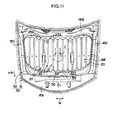
- Fig. 11 is a plan view illustrating a hood 50 applied with the vehicle hood structure according to the second exemplary embodiment of the present invention, with some elements such as a hood outer panel 16 (see the double-dash intermittent lines) illustrated in a see-through state.
- a hood inner panel 52 of the hood 50 differs slightly in the shape of the front end portion of a central region 18E from the hood inner panel 18 (see Fig. 1 , etc.) of the first exemplary embodiment.
- Other parts of the configuration are effectively the same as in the first exemplary embodiment. Accordingly, configuration elements effectively the same as in the first exemplary embodiment are given the same reference numerals and further explanation thereof is omitted.
- a hood front-rear direction front end portion 22D of each bead 22 reaches the vicinity of a front edge portion 18A of the hood inner panel 52, and the front end portions 22D are arranged in a line in hood plan view. More specifically, the shape of the termination of the front end portions 22D of each of the beads 22 (the shape formed by the positions where they rise up) forms a circular arc shape of large radius in hood plan view, and the terminal positions (starting positions) of the beads 22 are set on a (gentle) imaginary circular arc shaped curved line of large radius running substantially along the hood width direction as seen in hood plan view.
- a hood front-rear direction front end portion of the central region 18E of the hood inner panel 52 is formed with a front wall section 56 running substantially along the hood width direction in a circular arc shape with large radius, in hood plan view.
- the front wall section 56 is provided further to the hood front side than a wave shaped section 20, and is inclined towards the hood bottom side on progression towards the hood front.
- the hood inner panel 52 is further formed with a ledge section 54 that connects together the wave shaped section 20 and the front wall section 56 and is formed substantially along the hood width direction in a circular arc shape of large radius, in hood plan view.
- the ledge section 54 is formed with a flat profile, with a hood top-bottom direction step formed between apex portions 22A of the beads 22 and the ledge section 54.
- a ridge line 58 at the connection location between the ledge section 54 and the front wall section 56 is formed substantially along the hood width direction in a circular arc shape of large radius in hood plan view.
- substantially the same operation is achieved to as described in the first exemplary embodiment, enabling impact absorption ability prior to secondary impact to improved when the head impactor C (impacting body) impacts the hood 50.
- the rigidity of the front wall section 28, 56 with respect to the impact load f can be adjusted by adjusting such factors as the angle of inclination of the front wall section 28, 56, the extension direction of the ridge line 30, 58, and/or the position of the ledge section 26, 54.
- Such adjustments enable the load prior to secondary impact to be controlled. For example, if the angle of inclination of the front wall section 28, 56 with respect to the horizontal direction is set smaller than in the exemplary embodiments described above, the deformation load of the front wall section 28, 56 when the head impactor C impacts the hood 14, 50 can be made smaller than in the exemplary embodiments described above.
- the apex portions 22A of the beads 22 (protruding portions) in the wave shaped section 20 are formed with a flat profile, and the bottom portion 24A sides of the indented portions 24 are formed in a curved circular arc shape (curved shape) as seen in a cross-section taken along the hood width direction.
- the apex portion side of the protruding portions of the wave shaped section 20 may be formed in a curved circular arc shape (curved shape) as seen in a cross-section taken along the hood width direction, and the bottom portions of the indented portions of the wave shaped section may be formed with a flat profile.
- the bottom portions of the indented portions of the wave shaped section may also be set so as to lie in the same plane as the ledge section.
- the hood front-rear direction front end portions 22B, 22D of the plural beads 22 (protruding portions) of the wave shaped section 20 are all arranged in a line in hood plan view.
- Such a configuration is preferable, however configuration may be made in the wave shaped section such that, for example, the majority of the hood front-rear direction front end portions 22B, 22D of the plural beads (protruding portions) are arranged in a line in hood plan view (a majority preferably including front end portions in the hood width direction central portion).
Landscapes
- Engineering & Computer Science (AREA)
- Mechanical Engineering (AREA)
- Chemical & Material Sciences (AREA)
- Combustion & Propulsion (AREA)
- Transportation (AREA)
- Superstructure Of Vehicle (AREA)
- Body Structure For Vehicles (AREA)
Abstract
Description
- The present invention relates to a vehicle hood structure that is applied to a vehicle such as an automobile.
- Known vehicle hood structures include structures wherein a hood outer panel and a hood inner panel are coupled together. From the perspective of pedestrian protection, in such structures the hood inner panel may include plural beads arranged alongside each other with length directions oriented in the vehicle body front-rear direction, forming a wave shaped profile (see for example Patent Document 1). In such structures, when an impacting body impacts the hood (appropriately referred to below as "primary impact"), a high proportion of the load acting on the impacting body prior to the impacting body impacting a rigid object at the bottom side of the hood inner panel (appropriately referred to below as "secondary impact") is load due to the inertia of the hood panel.
- Patent Document 1: Japanese Patent Application Laid-Open (JP-A) No.
2003-205866 - However, in such structures, the load acting on the impacting body prior to secondary impact is strongly influenced by the mass of the hood panel, and there is accordingly room for improvement from the perspective of improving impact absorption ability prior to secondary impact.
- In consideration of the above issues, an object of the present invention is to obtain a vehicle hood structure capable of improving impact absorption ability prior to secondary impact when an impacting body impacts the hood.
- A vehicle hood structure of a first aspect of the present invention includes a hood outer panel that configures an outer panel of a hood, and a hood inner panel that is disposed at a hood bottom side of the hood outer panel and that is coupled to the hood outer panel to configure an inner panel of the hood. The hood inner panel includes: a wave shaped section that is provided at a central region of the hood inner panel and that includes protruding portions oriented with a length direction in a hood front-rear direction to give protruding shapes on the hood outer panel side, and indented portions oriented with a length direction in the hood front-rear direction to give indented shapes on the hood outer panel side, the protruding portions and the indented portions provided alternately to form a wave shaped profile, and with hood front-rear direction front end portions of the protruding portions arranged in a line in a hood plan view; a front wall section that is provided to the hood inner panel further to a hood front side than the wave shaped section, that is inclined towards the hood bottom side on progression towards a hood front, and that is formed substantially along the hood width direction; and a ledge section that is formed substantially along the hood width direction and that connects together the wave shaped section and the front wall section in the hood inner panel.
- According to the vehicle hood structure of the first aspect of the present invention, the hood inner panel is disposed at the hood bottom side of the hood outer panel and coupled to the hood outer panel, and the hood inner panel is formed with the wave shaped section at a central portion thereof. The wave shaped section is alternately provided with the protruding portions and the indented portions respectively orientated with length directions in the hood front-rear direction to give a wave shaped profile. The wave shaped section accordingly has a comparatively high rigidity with respect to impact load.
- The front end portions of the protruding portions of the wave shaped section are arranged in a line in hood plan view, and the front wall section is provided further to the hood front side than the wave shaped section, inclined towards the hood bottom side on progression towards the hood front, and formed substantially along the hood width direction. Accordingly, when an impacting body impacts the hood and load is input to the wave shaped section, bending deformation towards the hood bottom side occurs in the ledge section that has a lower rigidity than the wave shaped section. The front wall section deforms so as to bulge out diagonally towards a hood front upper side accompanying the deformation of the ledge section. The hood outer panel displaces towards the hood bottom side due to the impact load, causing the hood outer panel to (directly or indirectly) contact a rear end portion side of the front wall section, after which the contact position of the hood outer panel and the front wall section gradually changes towards the hood front side. Accordingly, the rear end portion side of the front wall section undergoes bending deformation such that a plastic deformation location deforms so as to move progressively and continuously towards the hood front side (ironing deformation). Energy expended in plastic deformation is absorbed, thereby improving impact absorption ability prior to secondary impact.
- A second aspect of the present invention is the vehicle hood structure of the first aspect wherein a ridge line configuring the location of connection between the ledge section and the front wall section is formed along the hood width direction in a straight line shape in a hood plan view.
- According to the vehicle hood structure of the second aspect of the present invention, the ridge line configuring the location of connection between the ledge section and the front wall section is formed along the hood width direction in a straight line shape in hood plan view. When an impacting body impacts the hood, the plastic deformation location of the front wall section therefore becomes a straight line shaped fold-bend deformation portion along the hood width direction and moves stably towards the hood front side. Namely, the front wall section deforms with a stable deformation mode.
- As described above, the vehicle hood structure according to the first aspect of the present invention exhibits the excellent advantageous effect of enabling impact absorption ability prior to secondary impact when an impacting body impacts the hood to be improved.
- The vehicle hood structure according to the second aspect of the present invention exhibits the excellent advantageous effect of increasing the precision of impact absorption ability prior to secondary impact when an impacting body impacts the hood.
-
-
Fig. 1 is a plan view illustrating a hood applied with a vehicle hood structure according to a first exemplary embodiment of the present invention (with elements such as a hood outer panel shown in a see-through state). -
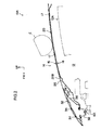
Fig. 2 is an enlarged cross-section of a state sectioned along line 2-2 ofFig. 1 . -
Fig. 3 is a side-view cross-section of the same section plane as inFig. 2 , illustrating a state where a head impactor has impacted the hood. -
Fig. 4 is a side-view cross-section illustrating a state in which a head impactor has impacted the hood and the front wall section of the hood inner panel is undergoing ironing deformation. -
Fig. 5 is a graph illustrating a relationship between a compound G and time when a head impactor has impacted a hood applied with the vehicle hood structure of the first exemplary embodiment of the present invention and a hood of a comparative structure under Japan New Car Assessment Program child test conditions. -
Fig. 6 is a graph illustrating a relationship between a synthetic G and stroke when a head impactor has impacted a hood applied with the vehicle hood structure of the first exemplary embodiment of the present invention and a hood of a comparative structure under Japan New Car Assessment Program child test conditions. -
Fig. 7 is a graph illustrating a relationship between a compound G and time when a head impactor has impacted a hood applied with the vehicle hood structure of the first exemplary embodiment of the present invention and a hood of a comparative structure under European Standards child conditions. -
Fig. 8 is a graph illustrating a relationship between a forward-backward G and stroke when a head impactor impacts a hood applied with the vehicle hood structure of the first exemplary embodiment of the present invention and a hood of a comparative structure under European Standards child conditions. -
Fig. 9 is a stacked graph illustrating a relationship between load prior to secondary impact and time in a hood of a comparative structure. -
Fig. 10 is a stacked graph illustrating a relationship between load prior to secondary impact and time in a hood applied with the vehicle hood structure of the first exemplary embodiment of the present invention. -
Fig. 11 is a plan view illustrating a hood applied with a vehicle hood structure of a second exemplary embodiment of the present invention (with elements such as a hood outer panel shown in a see-through state). - Explanation follows regarding a vehicle hood structure according to a first exemplary embodiment of the present invention, with reference to
Fig. 1 to Fig. 10 . In the drawings the arrow FR indicates the vehicle front side, the arrow UP indicates the vehicle top side, and the arrow W indicates the vehicle width direction as appropriate. In a closed state of the hood, the hood front-rear direction is the same direction as the vehicle front-rear direction, the hood top-bottom direction is the same direction as the vehicle top-bottom direction, and the hood width direction is the same direction as the vehicle width direction. -
Fig. 1 is a plan view illustrating ahood 14 applied to a vehicle hood structure according to the present exemplary embodiment with elements such as a hood outer panel 16 (refer to the double-dash intermittent line) shown in a see-through state.Fig. 2 is an enlarged cross-section taken along line 2-2 inFig. 1 . - As shown in
Fig. 2 , a vehicle front section 10A of an automobile (vehicle) is provided with a hood (engine hood) 14 that covers anengine compartment 12 such that theengine compartement 12 can be opened and closed. Arigid body 12A such as a power unit is installed inside theengine compartment 12 covered by thehood 14. - The
hood 14 is made out of metal (out of an aluminum alloy in the present exemplary embodiment, by way of an example). As shown inFig. 1 , thehood 14 is set such that the hood width direction dimension is longer than the hood front-rear direction dimension. Hinges (not shown in the drawings) are provided at both sides of a hood front-rear direction rear end portion of thehood 14. Thehood 14 is according capable of rotational movement about a hood width direction axis at the hinges (not shown in the drawings), namely capable of opening and closing. - As shown in
Fig. 2 , thehood 14 is configured including a hoodouter panel 16 configuring an outside panel of thehood 14 and extending substantially along the vehicle front-rear direction, and a hoodinner panel 18 disposed at the hood bottom side of the hoodouter panel 16 and coupled to the hoodouter panel 16, the hoodinner panel 18 configuring an inside panel of thehood 14.Dent reinforcement 32 is disposed at a central region of a hood front-rear direction front end portion of thehood 14 andstriker reinforcement 36 is disposed at the hood bottom side of thedent reinforcement 32. - The
striker reinforcement 36 is a curved plate shaped metal reinforcement member disposed between the hoodouter panel 16 and the hoodinner panel 18 to secure rigidity at the periphery of ahood striker 38. Note that configuration is made such that thehood striker 38 is latched by alatch 40 on the vehicle body side when thehood 14 is in a closed position. Thehood 14 is retained in the closed position by the latch 40 latching to thehood striker 38. A hood front-rear direction intermediate portion of thestriker reinforcement 36 is joined to the hoodinner panel 18, and hood front-rear direction end portions of thestriker reinforcement 36 are joined to the back face of hood front-rear direction end portion sides of thedent reinforcement 32. - The
dent reinforcement 32 is made from metal in a plate shape, and is disposed between the hoodouter panel 16 and the hoodinner panel 18 towards the hoodouter panel 16 side. Thedent reinforcement 32 is a reinforcement member for suppressing deformation of the hoodouter panel 16 when thehood 14 is closed. Thedent reinforcement 32 extends substantially along the hoodouter panel 16 and is joined (fixed) to the back face of the hoodouter panel 16 bymastic 34. - The hood
outer panel 16 and the hoodinner panel 18 are both formed by press forming an aluminum alloy sheet (in the present exemplary embodiment, for example, a JIS standard 6000 series aluminum alloy sheet is used). The plate thickness of the hoodouter panel 16 and the plate thickness of the hoodinner panel 18 are set in consideration of various perspectives such as achieving a weight saving and pedestrian protection characteristics. An outer peripheral portion of the hoodouter panel 16 is coupled to the hoodinner panel 18 by hemming processing. In an assembled state of the hoodouter panel 16 and the hood inner panel 18 (a panel structure body state), the two panels form a closed cross-section structure (what is referred to as a clam shell structure in the present exemplary embodiment), forming a gap (void) in the hood top-bottom direction between the two panels. - As shown in
Fig. 1 , an outer peripheral edge section of the hoodinner panel 18 is configured by afront edge portion 18A, arear edge portion 18B, and left and right hood widthdirection edge portions central region 18E is configured inside thefront edge portion 18A, therear edge portion 18B and the left and right hood widthdirection edge portions -
Plural beads 22 serving as protruding portions are formed in thecentral region 18E of the hoodinner panel 18. Eachbead 22 is oriented with the length direction in the hood front-rear direction is provided withapex portions 22A such that, when viewed in cross-section orthogonal to the length direction of thebeads 22, the panel (the hood inner panel 18) in thecentral region 18E rises up towards the hoodouter panel 16 side to form protruding shapes. Theapex portions 22A are formed with a flat profile. The front faces of theapex portions 22A are disposed substantially parallel to the hoodouter panel 16. Part of theapex portions 22A of thebeads 22 are joined to the back face of the hoodouter panel 16 through mastic 17 (seeFig. 2 ), an adhesive. - A hood front-rear direction
front end portion 22B of each of thebeads 22 reaches the vicinity of thefront edge portion 18A of the hoodinner panel 18, and thefront end portions 22B are arranged in a line in hood plan view. More specifically, the shape of the termination of thefront end portions 22B of each of the beads 22 (the shape formed by the positions where they rise up) forms a straight line along the hood width direction in hood plan view, and the terminal positions (starting positions) of thebeads 22 are set on an imaginary straight line across the hood width direction with aligned hood front-rear direction positions in hood plan view. Hood front-rear direction rear end portions 22C of each of thebeads 22 reach the vicinity of therear edge portion 18B of the hoodinner panel 18. Thebeads 22 configure a framework that raises the hood front-rear direction bending rigidity of thecentral region 18E of the hoodinner panel 18. -
Indented portions 24 having an indented profile on the hoodouter panel 16 side and oriented with their length directions in the hood front-rear direction are respectively formed betweenadjacent beads 22 in thecentral region 18E of the hoodinner panel 18 in which theplural beads 22 are lined up in parallel.Bottom portion 24A sides of theindented portions 24 are formed with a curved circular arc profile (curved line profile) cross-section as viewed along a plane orthogonal to the length direction of theindented portions 24. - A wave shaped
section 20 with a wave shaped (wave form) cross-section is formed across virtually the entire region of thecentral region 18E by the beads 22 (protruding portions) andindented portions 24 alternately provided across the hood width direction in the above manner. The wave shapedsection 20 faces therigid body 12A inside theengine compartment 12, as shown inFig. 2 . - Note that the wave shaped profile of the wave shaped
section 20 illustrated inFig. 1 is set, for example, with a wavelength p of 70mm ≤ p ≤ 100mm. When theapex portions 22A are formed with a flat profile as in the present exemplary embodiment, the wavelength p is the horizontal distance (hood width direction distance) from a width direction central position (a wavelength direction central position) of a givenapex portion 22A to the width direction central portion (the wavelength direction central position) of an adjacentapex position 22A. A height h of the wave shaped profile of the wave shaped section 20 (in other words, the height of the beads 22) is set, for example, at 8.5mm ≤ h ≤ 10.5mm, from the viewpoint of securing rigidity of the wave shapedsection 20. - A hood front-rear direction front end portion of the
central region 18E of the hoodinner panel 18 is formed with afront wall section 28 substantially along the hood width direction. Thefront wall section 28 is provided further to the hood front side than the wave shapedsection 20, and as shown inFig. 2 , is inclined towards the hood bottom side on progression towards the hood front. In the present exemplary embodiment, thefront wall section 28 is disposed further to the hood rear side than a rear end side joinportion 37 between thestriker reinforcement 36 and thedent reinforcement 32. - As shown in
Fig. 1 , the hoodinner panel 18 is formed with aledge section 26 that connects together the wave shapedsection 20 and thefront wall section 28. Theledge section 26 is formed in a straight line shape substantially along the hood width direction. Theledge section 26 is formed with a flat profile with a hood top-bottom direction step formed between theapex portions 22A of thebeads 22 and theledge section 26. Aridge line 30 that is the connection location of theledge section 26 and thefront wall section 28 is formed in a straight line shape along the hood width direction in hood plan view. - Explanation follows regarding operation and advantageous effects of the above exemplary embodiment.
- As shown in
Fig. 1 , the wave shapedsection 20 formed to thecentral region 18E of the hoodinner panel 18 has a comparatively high rigidity to impact load due to being formed with a wave shaped profile by the alternately provided beads 22 (protruding portions) andindented portions 24 with length directions respectively oriented in the hood front-rear direction. - The
front end portions 22B of thebeads 22 of the wave shapedsection 20 are arranged in a line in as seen in hood plan view, and thefront wall section 28 provided further to the hood front side than the wave shapedsection 20 is formed running substantially along the hood width direction and inclined towards the hood bottom side on progression towards the hood front. The wave shapedsection 20 and thefront wall section 28 are connected by theledge section 26 that is formed substantially along the hood width direction. Accordingly, as shown inFig. 3 , when a head impactor C that is modeled on the head of a pedestrian and serves as an impacting body impacts thehood 14, inputting an impact load f to the wave shapedsection 20, bending deformation towards the hood bottom side occurs in theledge section 26 that has lower rigidity than the wave shapedsection 20. Thefront wall section 28 deforms to bulge diagonally towards a hood front upper side, accompanying the deformation of theledge section 26. Note that inFig. 3 , the state of thefront wall section 28 prior to deformation is indicated by the double-dash intermittent line. - In response, as shown in
Fig. 4 , since the hoodouter panel 16 displaces towards the hood bottom side under the impact load f, the hoodouter panel 16 contacts the rear end portion side of thefront wall section 28, after which the contact position of the hoodouter panel 16 and thefront wall section 28 gradually changes towards the hood front side. Accordingly, a rear end portion side of thefront wall section 28 undergoes bending deformation such that a plastic deformation location S deforms so as to move progressively and continuously towards the hood front side (namely ironing deformation occurs with continuous bending deformation in the front wall section 28). In other words, ironing deformation of thefront wall section 28 is induced by theledge section 26 undergoing bending deformation. - More specific explanation follows regarding the ironing deformation of the
front wall section 28, with reference toFig. 4 . When the hoodouter panel 16 contacts thefront wall section 28, the plastic deformation location S moves progressively and continuously from a deformation start position b1 indicated by the double-dash intermittent line, through a mid-deformation position b2 indicated by the unbroken line, and then to a position b3 indicated by the single-dash intermittent line. The continuous movement of the plastic deformation location S continues until the hoodinner panel 18 impacts therigid body 12A (secondary impact) at the bottom side of the hoodinner panel 18. Reaction force (deformation load) due to the ironing deformation of thefront wall section 28 occurs continuously in the hoodinner panel 18 prior to secondary impact. Impact absorption ability prior to secondary impact is improved due to the energy expended in plastic deformation of thefront wall section 28 being absorbed. - Note that during deformation of the
front wall section 28, large plastic distortion occurs in thefront wall section 28, and large plastic deformation occurs at abending deformation portion 16A of the hood outer panel 16 (a location to the hood top side of the rear end side joinportion 37 between thestriker reinforcement 36 and the dent reinforcement 32). - As shown in
Fig. 1 , in the vehicle hood structure of the present exemplary embodiment, theridge line 30 that is the connection location of theledge section 26 and thefront wall section 28 is formed in a straight line shape along the hood width direction in hood plan view. The plastic deformation location S illustrated inFig. 4 therefore becomes a straight line fold-bend deformation portion along the hood width direction and moves stably towards the hood front side. Namely, the precision of impact absorption ability prior to secondary impact is raised due to thefront wall section 28 deforming with a stable deformation mode. - Supplementary explanation follows of the above, drawing comparison with a comparative structure. For example, the operation and advantageous effects described above would not be obtained in a comparative structure wherein a ledge section (26) is not present between a wave shaped section (20) and a front wall section (28), and the front end of the wave shaped section (20) undulates in plan view. Namely, in such a comparative structure, when the head impactor (C) impacts the hood (14) and impact load (f) is input to the wave shaped section (20), hardly any bending deformation (fold-bend deformation) occurs between the wave shaped section (20) and the front wall section (28), and the front wall section (28) accordingly displaces towards the hood bottom side whilst hardly deforming at all. Accordingly, very little deformation load can be obtained from the hood inner panel (18).
By contrast, in the present exemplary embodiment, since thefront wall section 28 undergoes progressive deformation as described above, the deformation load due to the hoodinner panel 18 increases. - Supplementary explanation follows regarding load due to inertia and deformation load of the hood (14) during an impact of the head impactor (C), with reference to
Fig. 9 andFig. 10 .Fig. 9 andFig. 10 are stacked graphs illustrating relationship characteristics of a load F (N) prior to secondary impact and time t (ms) when the head impactor (C) is caused to impact the hood (14) under Japan New Car Assessment Program (JNCAP) test conditions.Fig. 9 shows characteristics of a hood of the comparative structure, andFig. 10 shows characteristics of a hood with the same structure as the present exemplary embodiment with the beads (22) having a height of 8.5mm. InFig. 9 andFig. 10 , P1 indicates the deformation load of the hood inner panel, P2 indicates the load due to inertia of the hood inner panel, P3 indicates the deformation load of the hood outer panel, and P4 indicates the load due to inertia of the hood outer panel, whilst P5 indicates load (deformation load and load due to inertia) at other locations. - As shown in
Fig. 9 andFig. 10 , it can be seen that in the hood according to the comparative structure (seeFig. 9 ), there is a larger proportion of load due to the hood inner panel inertial load P2 and a larger proportion of load due to the hood outer panel inertial load P4 than in the hood according to the present exemplary embodiment (seeFig. 10 ). It can be seen that the hood according to the present exemplary embodiment (seeFig. 10 ) has a larger proportion of load due to the hood inner panel deformation load P1 than in the hood according to the comparative structure (seeFig. 9 ). In other words, in the hood according to the present exemplary embodiment (seeFig. 10 ), deformation load is the dominant load acting on the head impactor (C) prior to secondary impact. It is accordingly more difficult for the mass of the hood to affect the load than in the hood of the comparative structure (seeFig. 9 ). - Explanation follows with reference to graphs
Fig. 5 to Fig. 8 regarding impact absorption characteristics of a hood applied with the vehicle hood structure according to the present exemplary embodiment, drawing comparison with the impact absorption characteristics of a hood according to the comparative structure. -
Fig. 5 and Fig. 6 illustrate characteristics when a head impactor is caused to impact a hood under Japan New Car Assessment Program (JNCAP) child test conditions.Fig. 5 is a graph showing a relationship between a triaxial compound acceleration G (compound G (m/s2)) and time t (ms).Fig. 6 is a graph showing a relationship between acceleration G (forward-backward G (m/s2) in the head impactor impact direction and stroke S (mm). -
Fig. 7 andFig. 8 illustrate characteristics when a head impactor is caused to impact under European Standards child test conditions.Fig. 7 is a graph showing a relationship between a triaxial compound acceleration G (compound G (m/s2)) and time t (ms).Fig. 8 is a graph showing a relationship between acceleration G (forward-backward G (m/s2) in the head impactor impact direction and stroke S (mm). - Note that the hood impact position is indicated by the head impactor C shown by the double-dash intermittent line in
Fig. 1 , and is set as a central portion of the wave shaped section (20) in plan view. The head impactor impact direction acceleration value is effectively virtually the same as the triaxial compound acceleration value. - In
Fig. 5 to Fig. 8 , the solid line indicates characteristics of a hood with a bead (22) height of 10.5mm in a structure the same as the vehicle hood structure according to the present exemplary embodiment. The double-dash intermittent line indicates characteristics of a hood with a bead (22) height of 8.5mm in a structure the same as the vehicle hood structure according to the present exemplary embodiment. The dotted line indicates characteristics of a hood of the comparative structure employed to generateFig. 9 . InFig. 5 andFig. 7 , the region enclosed by the single-dash intermittent line Z indicates the time of secondary impact and immediately before and after. - As shown in
Fig. 5 andFig. 7 , a falloff in acceleration prior to secondary impact is slightly suppressed in the vehicle hood structure according to the present exemplary embodiment (see the solid line and double-dash intermittent line) compared to in the comparative structure (see the dotted line). InFig. 5 to Fig. 8 , it can be seen that the acceleration is smoothed out more in the vehicle hood structure according to the present exemplary embodiment (see the solid line and double-dash intermittent line) than in the comparative structure (see the dotted line). Namely, in the vehicle hood structure according to the present exemplary embodiment (see the solid line and double-dash intermittent line), load prior to secondary impact is controlled and the amount of energy absorbed prior to secondary impact is increased. - Further explanation follows, drawing comparison with another comparative structure. For example, in another comparative structure wherein beads formed to a hood inner panel is configured to readily collapse under vertical pressure during secondary impact by setting large bead heights and widths, although impact absorption ability is raised after secondary impact, the impact absorption ability prior to secondary impact is still greatly influenced by the mass of the hood panel. Namely, even with such a comparative example, load due to inertia is a large proportion of load prior to secondary impact. Accordingly, it is difficult to control load (reaction force) prior to secondary impact. By contrast, in the vehicle hood structure of the present exemplary embodiment it is easier to control load (reaction force) prior to secondary impact due to raising the proportion of load exhibited by deformation load in the hood inner panel 18 (see
Fig. 2 , etc.) in the load prior to secondary impact. - As explained above, according to the vehicle hood structure of the present exemplary embodiment, the impact absorption ability prior to secondary impact can be improved when the head impactor C (impacting body) illustrated for example in
Fig. 2 impacts thehood 14. - Explanation follows regarding a vehicle hood structure according to a second exemplary embodiment of the present invention, with reference to
Fig. 11. Fig. 11 is a plan view illustrating ahood 50 applied with the vehicle hood structure according to the second exemplary embodiment of the present invention, with some elements such as a hood outer panel 16 (see the double-dash intermittent lines) illustrated in a see-through state. - As shown in
Fig. 11 , a hoodinner panel 52 of thehood 50 differs slightly in the shape of the front end portion of acentral region 18E from the hood inner panel 18 (seeFig. 1 , etc.) of the first exemplary embodiment. Other parts of the configuration are effectively the same as in the first exemplary embodiment. Accordingly, configuration elements effectively the same as in the first exemplary embodiment are given the same reference numerals and further explanation thereof is omitted. - A hood front-rear direction
front end portion 22D of eachbead 22 reaches the vicinity of afront edge portion 18A of the hoodinner panel 52, and thefront end portions 22D are arranged in a line in hood plan view. More specifically, the shape of the termination of thefront end portions 22D of each of the beads 22 (the shape formed by the positions where they rise up) forms a circular arc shape of large radius in hood plan view, and the terminal positions (starting positions) of thebeads 22 are set on a (gentle) imaginary circular arc shaped curved line of large radius running substantially along the hood width direction as seen in hood plan view. - A hood front-rear direction front end portion of the
central region 18E of the hoodinner panel 52 is formed with a front wall section 56 running substantially along the hood width direction in a circular arc shape with large radius, in hood plan view. The front wall section 56 is provided further to the hood front side than a wave shapedsection 20, and is inclined towards the hood bottom side on progression towards the hood front. - The hood
inner panel 52 is further formed with aledge section 54 that connects together the wave shapedsection 20 and the front wall section 56 and is formed substantially along the hood width direction in a circular arc shape of large radius, in hood plan view. Theledge section 54 is formed with a flat profile, with a hood top-bottom direction step formed betweenapex portions 22A of thebeads 22 and theledge section 54. Aridge line 58 at the connection location between theledge section 54 and the front wall section 56 is formed substantially along the hood width direction in a circular arc shape of large radius in hood plan view. - According to the configuration of the present exemplary embodiment, substantially the same operation is achieved to as described in the first exemplary embodiment, enabling impact absorption ability prior to secondary impact to improved when the head impactor C (impacting body) impacts the
hood 50. - Note that in the above exemplary embodiments the rigidity of the
front wall section 28, 56 with respect to the impact load f can be adjusted by adjusting such factors as the angle of inclination of thefront wall section 28, 56, the extension direction of theridge line ledge section front wall section 28, 56 with respect to the horizontal direction is set smaller than in the exemplary embodiments described above, the deformation load of thefront wall section 28, 56 when the head impactor C impacts thehood - In the exemplary embodiments described above, the
apex portions 22A of the beads 22 (protruding portions) in the wave shapedsection 20 are formed with a flat profile, and thebottom portion 24A sides of theindented portions 24 are formed in a curved circular arc shape (curved shape) as seen in a cross-section taken along the hood width direction. However, the apex portion side of the protruding portions of the wave shapedsection 20 may be formed in a curved circular arc shape (curved shape) as seen in a cross-section taken along the hood width direction, and the bottom portions of the indented portions of the wave shaped section may be formed with a flat profile. The bottom portions of the indented portions of the wave shaped section may also be set so as to lie in the same plane as the ledge section. - In the exemplary embodiments described above, the hood front-rear direction
front end portions section 20 are all arranged in a line in hood plan view. Such a configuration is preferable, however configuration may be made in the wave shaped section such that, for example, the majority of the hood front-rear directionfront end portions
Claims (2)
- A vehicle hood structure comprising a hood outer panel that configures an outer panel of a hood, and a hood inner panel that is disposed at a hood bottom side of the hood outer panel and that is coupled to the hood outer panel to configure an inner panel of the hood;
the hood inner panel comprising:a wave shaped section that is provided at a central region of the hood inner panel and that includes protruding portions oriented with a length direction in a hood front-rear direction to give protruding shapes on the hood outer panel side, and indented portions oriented with a length direction in the hood front-rear direction to give indented shapes on the hood outer panel side, the protruding portions and the indented portions provided alternately to form a wave shaped profile, and with hood front-rear direction front end portions of the protruding portions arranged in a line in a hood plan view;a front wall section that is provided to the hood inner panel further to a hood front side than the wave shaped section, that is inclined towards the hood bottom side on progression towards a hood front, and that is formed substantially along the hood width direction; anda ledge section that is formed substantially along the hood width direction and that connects together the wave shaped section and the front wall section in the hood inner panel. - The vehicle hood structure of claim 1 wherein a ridge line configuring the location of connection between the ledge section and the front wall section is formed along the hood width direction in a straight line shape in a hood plan view.
Applications Claiming Priority (1)
| Application Number | Priority Date | Filing Date | Title |
|---|---|---|---|
| PCT/JP2010/061645 WO2012004881A1 (en) | 2010-07-08 | 2010-07-08 | Vehicle hood structure |
Publications (3)
| Publication Number | Publication Date |
|---|---|
| EP2591987A1 true EP2591987A1 (en) | 2013-05-15 |
| EP2591987A4 EP2591987A4 (en) | 2013-05-22 |
| EP2591987B1 EP2591987B1 (en) | 2014-06-04 |
Family
ID=45440880
Family Applications (1)
| Application Number | Title | Priority Date | Filing Date |
|---|---|---|---|
| EP10854435.4A Not-in-force EP2591987B1 (en) | 2010-07-08 | 2010-07-08 | Vehicle hood structure |
Country Status (5)
| Country | Link |
|---|---|
| US (1) | US9150256B2 (en) |
| EP (1) | EP2591987B1 (en) |
| JP (1) | JP5316714B2 (en) |
| CN (1) | CN102985297B (en) |
| WO (1) | WO2012004881A1 (en) |
Cited By (1)
| Publication number | Priority date | Publication date | Assignee | Title |
|---|---|---|---|---|
| FR3097809A1 (en) * | 2019-06-28 | 2021-01-01 | Renault S.A.S | Hood, in particular in composite material, for a vehicle. |
Families Citing this family (9)
| Publication number | Priority date | Publication date | Assignee | Title |
|---|---|---|---|---|
| JP6019408B2 (en) * | 2013-09-25 | 2016-11-02 | トヨタ車体株式会社 | Passenger car hood structure |
| US9868472B2 (en) * | 2014-09-19 | 2018-01-16 | Mazda Motor Corporation | Bonnet structure of automotive vehicle |
| JP6233327B2 (en) * | 2015-02-05 | 2017-11-22 | トヨタ自動車株式会社 | VEHICLE PANEL STRUCTURE AND METHOD FOR MANUFACTURING VEHICLE PANEL STRUCTURE |
| JP6718726B2 (en) * | 2016-03-31 | 2020-07-08 | 株式会社神戸製鋼所 | Vehicle hood |
| JP6708070B2 (en) * | 2016-09-09 | 2020-06-10 | 三菱自動車工業株式会社 | Vehicle hood |
| JP6764453B2 (en) * | 2018-09-27 | 2020-09-30 | 本田技研工業株式会社 | Body front structure |
| FR3109356A1 (en) | 2020-04-16 | 2021-10-22 | Psa Automobiles Sa | MOTOR VEHICLE HOOD WITH SIDE EXTENSIONS |
| US11628888B2 (en) * | 2020-10-02 | 2023-04-18 | GM Global Technology Operations LLC | Enclosed volume sandwich hood |
| US11608026B2 (en) * | 2020-12-10 | 2023-03-21 | Fca Us Llc | Energy absorbing member beneath vehicle hood |
Family Cites Families (12)
| Publication number | Priority date | Publication date | Assignee | Title |
|---|---|---|---|---|
| US7150496B2 (en) * | 2000-12-13 | 2006-12-19 | Kobe Steel, Ltd. | Panel structure for car body hood |
| JP3674918B2 (en) | 2000-12-13 | 2005-07-27 | 株式会社神戸製鋼所 | Panel structure for body hood |
| JP2005075176A (en) * | 2003-09-01 | 2005-03-24 | Toyota Motor Corp | Vehicle hood structure |
| JP2005075163A (en) | 2003-09-01 | 2005-03-24 | Toyota Motor Corp | Vehicle hood structure |
| JP4422454B2 (en) * | 2003-09-22 | 2010-02-24 | トヨタ自動車株式会社 | Vehicle hood structure |
| JP2006044542A (en) | 2004-08-06 | 2006-02-16 | Kanto Auto Works Ltd | Automotive hood structure |
| JP2006044543A (en) | 2004-08-06 | 2006-02-16 | Kanto Auto Works Ltd | Automotive hood structure |
| ATE473903T1 (en) * | 2004-12-02 | 2010-07-15 | Kobe Steel Ltd | WALL STRUCTURE FOR VEHICLE BODY |
| JP4857595B2 (en) * | 2005-04-27 | 2012-01-18 | マツダ株式会社 | Front body structure of automobile |
| JP4730043B2 (en) * | 2005-09-30 | 2011-07-20 | トヨタ自動車株式会社 | Hood structure |
| JP2009040168A (en) | 2007-08-07 | 2009-02-26 | Kanto Auto Works Ltd | Vehicle hood structure |
| JP4407755B2 (en) | 2008-02-04 | 2010-02-03 | トヨタ自動車株式会社 | Vehicle hood structure |
-
2010
- 2010-07-08 EP EP10854435.4A patent/EP2591987B1/en not_active Not-in-force
- 2010-07-08 US US13/808,611 patent/US9150256B2/en not_active Expired - Fee Related
- 2010-07-08 WO PCT/JP2010/061645 patent/WO2012004881A1/en not_active Ceased
- 2010-07-08 CN CN201080067954.4A patent/CN102985297B/en not_active Expired - Fee Related
- 2010-07-08 JP JP2012523479A patent/JP5316714B2/en active Active
Non-Patent Citations (2)
| Title |
|---|
| No further relevant documents disclosed * |
| See also references of WO2012004881A1 * |
Cited By (1)
| Publication number | Priority date | Publication date | Assignee | Title |
|---|---|---|---|---|
| FR3097809A1 (en) * | 2019-06-28 | 2021-01-01 | Renault S.A.S | Hood, in particular in composite material, for a vehicle. |
Also Published As
| Publication number | Publication date |
|---|---|
| WO2012004881A1 (en) | 2012-01-12 |
| US9150256B2 (en) | 2015-10-06 |
| JP5316714B2 (en) | 2013-10-16 |
| US20130106142A1 (en) | 2013-05-02 |
| CN102985297B (en) | 2014-10-15 |
| EP2591987A4 (en) | 2013-05-22 |
| JPWO2012004881A1 (en) | 2013-09-02 |
| CN102985297A (en) | 2013-03-20 |
| EP2591987B1 (en) | 2014-06-04 |
Similar Documents
| Publication | Publication Date | Title |
|---|---|---|
| EP2591987B1 (en) | Vehicle hood structure | |
| EP2529998B1 (en) | Hood structure of vehicle | |
| US9868472B2 (en) | Bonnet structure of automotive vehicle | |
| JP5407372B2 (en) | Vehicle side body structure | |
| EP2551172B1 (en) | Hood structure for vehicle | |
| CN1315684C (en) | Vehicle hood structure | |
| CN101939209B (en) | Vehicle hood structure | |
| CN107284531B (en) | Engine cover for vehicle | |
| EP3293090B1 (en) | Hood of vehicle | |
| JP5459054B2 (en) | Body parts for vehicles | |
| JP5717509B2 (en) | Hood panel for vehicle | |
| JP5692033B2 (en) | Vehicle hood structure | |
| JP5542082B2 (en) | Hood panel for vehicle | |
| WO2008066043A1 (en) | Front structure for vehicle | |
| JP2014162440A (en) | Front door structure for center pillar-less vehicle | |
| JP2005022459A (en) | Hood support structure | |
| CN217374103U (en) | Door assembly for vehicle and vehicle having the same | |
| JP4300841B2 (en) | Door belt line structure | |
| CN116648401A (en) | Motor vehicle hood structure | |
| JPH10138759A (en) | Automotive door panel structure | |
| CN118790354A (en) | Vehicle door sill structure and vehicle | |
| CN120817149A (en) | Vehicle body bracket assembly and vehicle | |
| JP2022129107A (en) | Vehicle side part structure | |
| JP2012171409A (en) | Cowl structure for vehicle |
Legal Events
| Date | Code | Title | Description |
|---|---|---|---|
| PUAI | Public reference made under article 153(3) epc to a published international application that has entered the european phase |
Free format text: ORIGINAL CODE: 0009012 |
|
| REG | Reference to a national code |
Ref country code: DE Ref legal event code: R079 Ref document number: 602010016566 Country of ref document: DE Free format text: PREVIOUS MAIN CLASS: B62D0025100000 Ipc: B60R0021340000 |
|
| 17P | Request for examination filed |
Effective date: 20130115 |
|
| AK | Designated contracting states |
Kind code of ref document: A1 Designated state(s): AL AT BE BG CH CY CZ DE DK EE ES FI FR GB GR HR HU IE IS IT LI LT LU LV MC MK MT NL NO PL PT RO SE SI SK SM TR |
|
| A4 | Supplementary search report drawn up and despatched |
Effective date: 20130418 |
|
| RIC1 | Information provided on ipc code assigned before grant |
Ipc: B60R 21/01 20060101ALI20130412BHEP Ipc: B60R 21/34 20110101AFI20130412BHEP Ipc: B62D 25/10 20060101ALI20130412BHEP |
|
| DAX | Request for extension of the european patent (deleted) | ||
| GRAP | Despatch of communication of intention to grant a patent |
Free format text: ORIGINAL CODE: EPIDOSNIGR1 |
|
| INTG | Intention to grant announced |
Effective date: 20131217 |
|
| GRAS | Grant fee paid |
Free format text: ORIGINAL CODE: EPIDOSNIGR3 |
|
| GRAA | (expected) grant |
Free format text: ORIGINAL CODE: 0009210 |
|
| AK | Designated contracting states |
Kind code of ref document: B1 Designated state(s): AL AT BE BG CH CY CZ DE DK EE ES FI FR GB GR HR HU IE IS IT LI LT LU LV MC MK MT NL NO PL PT RO SE SI SK SM TR |
|
| REG | Reference to a national code |
Ref country code: GB Ref legal event code: FG4D |
|
| REG | Reference to a national code |
Ref country code: CH Ref legal event code: EP |
|
| REG | Reference to a national code |
Ref country code: AT Ref legal event code: REF Ref document number: 670892 Country of ref document: AT Kind code of ref document: T Effective date: 20140615 |
|
| REG | Reference to a national code |
Ref country code: IE Ref legal event code: FG4D |
|
| REG | Reference to a national code |
Ref country code: DE Ref legal event code: R096 Ref document number: 602010016566 Country of ref document: DE Effective date: 20140717 |
|
| REG | Reference to a national code |
Ref country code: AT Ref legal event code: MK05 Ref document number: 670892 Country of ref document: AT Kind code of ref document: T Effective date: 20140604 |
|
| REG | Reference to a national code |
Ref country code: NL Ref legal event code: VDEP Effective date: 20140604 |
|
| PG25 | Lapsed in a contracting state [announced via postgrant information from national office to epo] |
Ref country code: NO Free format text: LAPSE BECAUSE OF FAILURE TO SUBMIT A TRANSLATION OF THE DESCRIPTION OR TO PAY THE FEE WITHIN THE PRESCRIBED TIME-LIMIT Effective date: 20140904 Ref country code: LT Free format text: LAPSE BECAUSE OF FAILURE TO SUBMIT A TRANSLATION OF THE DESCRIPTION OR TO PAY THE FEE WITHIN THE PRESCRIBED TIME-LIMIT Effective date: 20140604 Ref country code: GR Free format text: LAPSE BECAUSE OF FAILURE TO SUBMIT A TRANSLATION OF THE DESCRIPTION OR TO PAY THE FEE WITHIN THE PRESCRIBED TIME-LIMIT Effective date: 20140905 Ref country code: CY Free format text: LAPSE BECAUSE OF FAILURE TO SUBMIT A TRANSLATION OF THE DESCRIPTION OR TO PAY THE FEE WITHIN THE PRESCRIBED TIME-LIMIT Effective date: 20140604 Ref country code: FI Free format text: LAPSE BECAUSE OF FAILURE TO SUBMIT A TRANSLATION OF THE DESCRIPTION OR TO PAY THE FEE WITHIN THE PRESCRIBED TIME-LIMIT Effective date: 20140604 |
|
| REG | Reference to a national code |
Ref country code: LT Ref legal event code: MG4D |
|
| PG25 | Lapsed in a contracting state [announced via postgrant information from national office to epo] |
Ref country code: LV Free format text: LAPSE BECAUSE OF FAILURE TO SUBMIT A TRANSLATION OF THE DESCRIPTION OR TO PAY THE FEE WITHIN THE PRESCRIBED TIME-LIMIT Effective date: 20140604 Ref country code: SE Free format text: LAPSE BECAUSE OF FAILURE TO SUBMIT A TRANSLATION OF THE DESCRIPTION OR TO PAY THE FEE WITHIN THE PRESCRIBED TIME-LIMIT Effective date: 20140604 Ref country code: HR Free format text: LAPSE BECAUSE OF FAILURE TO SUBMIT A TRANSLATION OF THE DESCRIPTION OR TO PAY THE FEE WITHIN THE PRESCRIBED TIME-LIMIT Effective date: 20140604 Ref country code: AT Free format text: LAPSE BECAUSE OF FAILURE TO SUBMIT A TRANSLATION OF THE DESCRIPTION OR TO PAY THE FEE WITHIN THE PRESCRIBED TIME-LIMIT Effective date: 20140604 |
|
| PG25 | Lapsed in a contracting state [announced via postgrant information from national office to epo] |
Ref country code: ES Free format text: LAPSE BECAUSE OF FAILURE TO SUBMIT A TRANSLATION OF THE DESCRIPTION OR TO PAY THE FEE WITHIN THE PRESCRIBED TIME-LIMIT Effective date: 20140604 Ref country code: SK Free format text: LAPSE BECAUSE OF FAILURE TO SUBMIT A TRANSLATION OF THE DESCRIPTION OR TO PAY THE FEE WITHIN THE PRESCRIBED TIME-LIMIT Effective date: 20140604 Ref country code: EE Free format text: LAPSE BECAUSE OF FAILURE TO SUBMIT A TRANSLATION OF THE DESCRIPTION OR TO PAY THE FEE WITHIN THE PRESCRIBED TIME-LIMIT Effective date: 20140604 Ref country code: PT Free format text: LAPSE BECAUSE OF FAILURE TO SUBMIT A TRANSLATION OF THE DESCRIPTION OR TO PAY THE FEE WITHIN THE PRESCRIBED TIME-LIMIT Effective date: 20141006 Ref country code: CZ Free format text: LAPSE BECAUSE OF FAILURE TO SUBMIT A TRANSLATION OF THE DESCRIPTION OR TO PAY THE FEE WITHIN THE PRESCRIBED TIME-LIMIT Effective date: 20140604 Ref country code: RO Free format text: LAPSE BECAUSE OF FAILURE TO SUBMIT A TRANSLATION OF THE DESCRIPTION OR TO PAY THE FEE WITHIN THE PRESCRIBED TIME-LIMIT Effective date: 20140604 |
|
| PG25 | Lapsed in a contracting state [announced via postgrant information from national office to epo] |
Ref country code: PL Free format text: LAPSE BECAUSE OF FAILURE TO SUBMIT A TRANSLATION OF THE DESCRIPTION OR TO PAY THE FEE WITHIN THE PRESCRIBED TIME-LIMIT Effective date: 20140604 Ref country code: IS Free format text: LAPSE BECAUSE OF FAILURE TO SUBMIT A TRANSLATION OF THE DESCRIPTION OR TO PAY THE FEE WITHIN THE PRESCRIBED TIME-LIMIT Effective date: 20141004 Ref country code: NL Free format text: LAPSE BECAUSE OF FAILURE TO SUBMIT A TRANSLATION OF THE DESCRIPTION OR TO PAY THE FEE WITHIN THE PRESCRIBED TIME-LIMIT Effective date: 20140604 |
|
| REG | Reference to a national code |
Ref country code: CH Ref legal event code: PL |
|
| REG | Reference to a national code |
Ref country code: DE Ref legal event code: R097 Ref document number: 602010016566 Country of ref document: DE |
|
| PG25 | Lapsed in a contracting state [announced via postgrant information from national office to epo] |
Ref country code: MC Free format text: LAPSE BECAUSE OF FAILURE TO SUBMIT A TRANSLATION OF THE DESCRIPTION OR TO PAY THE FEE WITHIN THE PRESCRIBED TIME-LIMIT Effective date: 20140604 |
|
| PLBE | No opposition filed within time limit |
Free format text: ORIGINAL CODE: 0009261 |
|
| STAA | Information on the status of an ep patent application or granted ep patent |
Free format text: STATUS: NO OPPOSITION FILED WITHIN TIME LIMIT |
|
| REG | Reference to a national code |
Ref country code: DE Ref legal event code: R084 Ref document number: 602010016566 Country of ref document: DE |
|
| REG | Reference to a national code |
Ref country code: IE Ref legal event code: MM4A |
|
| REG | Reference to a national code |
Ref country code: FR Ref legal event code: ST Effective date: 20150331 |
|
| PG25 | Lapsed in a contracting state [announced via postgrant information from national office to epo] |
Ref country code: DK Free format text: LAPSE BECAUSE OF FAILURE TO SUBMIT A TRANSLATION OF THE DESCRIPTION OR TO PAY THE FEE WITHIN THE PRESCRIBED TIME-LIMIT Effective date: 20140604 Ref country code: LI Free format text: LAPSE BECAUSE OF NON-PAYMENT OF DUE FEES Effective date: 20140731 Ref country code: IT Free format text: LAPSE BECAUSE OF FAILURE TO SUBMIT A TRANSLATION OF THE DESCRIPTION OR TO PAY THE FEE WITHIN THE PRESCRIBED TIME-LIMIT Effective date: 20140604 Ref country code: CH Free format text: LAPSE BECAUSE OF NON-PAYMENT OF DUE FEES Effective date: 20140731 |
|
| 26N | No opposition filed |
Effective date: 20150305 |
|
| GBPC | Gb: european patent ceased through non-payment of renewal fee |
Effective date: 20140904 |
|
| PG25 | Lapsed in a contracting state [announced via postgrant information from national office to epo] |
Ref country code: FR Free format text: LAPSE BECAUSE OF NON-PAYMENT OF DUE FEES Effective date: 20140804 |
|
| REG | Reference to a national code |
Ref country code: DE Ref legal event code: R084 Ref document number: 602010016566 Country of ref document: DE Effective date: 20150417 |
|
| REG | Reference to a national code |
Ref country code: DE Ref legal event code: R097 Ref document number: 602010016566 Country of ref document: DE Effective date: 20150305 |
|
| PG25 | Lapsed in a contracting state [announced via postgrant information from national office to epo] |
Ref country code: BE Free format text: LAPSE BECAUSE OF FAILURE TO SUBMIT A TRANSLATION OF THE DESCRIPTION OR TO PAY THE FEE WITHIN THE PRESCRIBED TIME-LIMIT Effective date: 20140604 |
|
| PG25 | Lapsed in a contracting state [announced via postgrant information from national office to epo] |
Ref country code: GB Free format text: LAPSE BECAUSE OF NON-PAYMENT OF DUE FEES Effective date: 20140904 Ref country code: SI Free format text: LAPSE BECAUSE OF FAILURE TO SUBMIT A TRANSLATION OF THE DESCRIPTION OR TO PAY THE FEE WITHIN THE PRESCRIBED TIME-LIMIT Effective date: 20140604 |
|
| PG25 | Lapsed in a contracting state [announced via postgrant information from national office to epo] |
Ref country code: IE Free format text: LAPSE BECAUSE OF NON-PAYMENT OF DUE FEES Effective date: 20140708 |
|
| PG25 | Lapsed in a contracting state [announced via postgrant information from national office to epo] |
Ref country code: SM Free format text: LAPSE BECAUSE OF FAILURE TO SUBMIT A TRANSLATION OF THE DESCRIPTION OR TO PAY THE FEE WITHIN THE PRESCRIBED TIME-LIMIT Effective date: 20140604 |
|
| PG25 | Lapsed in a contracting state [announced via postgrant information from national office to epo] |
Ref country code: MT Free format text: LAPSE BECAUSE OF FAILURE TO SUBMIT A TRANSLATION OF THE DESCRIPTION OR TO PAY THE FEE WITHIN THE PRESCRIBED TIME-LIMIT Effective date: 20140604 Ref country code: BG Free format text: LAPSE BECAUSE OF FAILURE TO SUBMIT A TRANSLATION OF THE DESCRIPTION OR TO PAY THE FEE WITHIN THE PRESCRIBED TIME-LIMIT Effective date: 20140604 |
|
| PG25 | Lapsed in a contracting state [announced via postgrant information from national office to epo] |
Ref country code: LU Free format text: LAPSE BECAUSE OF NON-PAYMENT OF DUE FEES Effective date: 20140708 Ref country code: HU Free format text: LAPSE BECAUSE OF FAILURE TO SUBMIT A TRANSLATION OF THE DESCRIPTION OR TO PAY THE FEE WITHIN THE PRESCRIBED TIME-LIMIT; INVALID AB INITIO Effective date: 20100708 Ref country code: TR Free format text: LAPSE BECAUSE OF FAILURE TO SUBMIT A TRANSLATION OF THE DESCRIPTION OR TO PAY THE FEE WITHIN THE PRESCRIBED TIME-LIMIT Effective date: 20140604 |
|
| PG25 | Lapsed in a contracting state [announced via postgrant information from national office to epo] |
Ref country code: MK Free format text: LAPSE BECAUSE OF FAILURE TO SUBMIT A TRANSLATION OF THE DESCRIPTION OR TO PAY THE FEE WITHIN THE PRESCRIBED TIME-LIMIT Effective date: 20140604 |
|
| PG25 | Lapsed in a contracting state [announced via postgrant information from national office to epo] |
Ref country code: AL Free format text: LAPSE BECAUSE OF FAILURE TO SUBMIT A TRANSLATION OF THE DESCRIPTION OR TO PAY THE FEE WITHIN THE PRESCRIBED TIME-LIMIT Effective date: 20140604 |
|
| PGFP | Annual fee paid to national office [announced via postgrant information from national office to epo] |
Ref country code: DE Payment date: 20210608 Year of fee payment: 12 |
|
| REG | Reference to a national code |
Ref country code: DE Ref legal event code: R119 Ref document number: 602010016566 Country of ref document: DE |
|
| PG25 | Lapsed in a contracting state [announced via postgrant information from national office to epo] |
Ref country code: DE Free format text: LAPSE BECAUSE OF NON-PAYMENT OF DUE FEES Effective date: 20230201 |