EP2591943A1 - Vehicle display device - Google Patents
Vehicle display device Download PDFInfo
- Publication number
- EP2591943A1 EP2591943A1 EP11803589.8A EP11803589A EP2591943A1 EP 2591943 A1 EP2591943 A1 EP 2591943A1 EP 11803589 A EP11803589 A EP 11803589A EP 2591943 A1 EP2591943 A1 EP 2591943A1
- Authority
- EP
- European Patent Office
- Prior art keywords
- drive force
- display
- wheels
- vehicle
- segment
- Prior art date
- Legal status (The legal status is an assumption and is not a legal conclusion. Google has not performed a legal analysis and makes no representation as to the accuracy of the status listed.)
- Granted
Links
Images



Classifications
-
- B—PERFORMING OPERATIONS; TRANSPORTING
- B60—VEHICLES IN GENERAL
- B60K—ARRANGEMENT OR MOUNTING OF PROPULSION UNITS OR OF TRANSMISSIONS IN VEHICLES; ARRANGEMENT OR MOUNTING OF PLURAL DIVERSE PRIME-MOVERS IN VEHICLES; AUXILIARY DRIVES FOR VEHICLES; INSTRUMENTATION OR DASHBOARDS FOR VEHICLES; ARRANGEMENTS IN CONNECTION WITH COOLING, AIR INTAKE, GAS EXHAUST OR FUEL SUPPLY OF PROPULSION UNITS IN VEHICLES
- B60K35/00—Instruments specially adapted for vehicles; Arrangement of instruments in or on vehicles
- B60K35/60—Instruments characterised by their location or relative disposition in or on vehicles
-
- B—PERFORMING OPERATIONS; TRANSPORTING
- B60—VEHICLES IN GENERAL
- B60W—CONJOINT CONTROL OF VEHICLE SUB-UNITS OF DIFFERENT TYPE OR DIFFERENT FUNCTION; CONTROL SYSTEMS SPECIALLY ADAPTED FOR HYBRID VEHICLES; ROAD VEHICLE DRIVE CONTROL SYSTEMS FOR PURPOSES NOT RELATED TO THE CONTROL OF A PARTICULAR SUB-UNIT
- B60W10/00—Conjoint control of vehicle sub-units of different type or different function
- B60W10/04—Conjoint control of vehicle sub-units of different type or different function including control of propulsion units
- B60W10/06—Conjoint control of vehicle sub-units of different type or different function including control of propulsion units including control of combustion engines
-
- B—PERFORMING OPERATIONS; TRANSPORTING
- B60—VEHICLES IN GENERAL
- B60K—ARRANGEMENT OR MOUNTING OF PROPULSION UNITS OR OF TRANSMISSIONS IN VEHICLES; ARRANGEMENT OR MOUNTING OF PLURAL DIVERSE PRIME-MOVERS IN VEHICLES; AUXILIARY DRIVES FOR VEHICLES; INSTRUMENTATION OR DASHBOARDS FOR VEHICLES; ARRANGEMENTS IN CONNECTION WITH COOLING, AIR INTAKE, GAS EXHAUST OR FUEL SUPPLY OF PROPULSION UNITS IN VEHICLES
- B60K35/00—Instruments specially adapted for vehicles; Arrangement of instruments in or on vehicles
- B60K35/20—Output arrangements, i.e. from vehicle to user, associated with vehicle functions or specially adapted therefor
- B60K35/21—Output arrangements, i.e. from vehicle to user, associated with vehicle functions or specially adapted therefor using visual output, e.g. blinking lights or matrix displays
- B60K35/215—Output arrangements, i.e. from vehicle to user, associated with vehicle functions or specially adapted therefor using visual output, e.g. blinking lights or matrix displays characterised by the combination of multiple visual outputs, e.g. combined instruments with analogue meters and additional displays
-
- B—PERFORMING OPERATIONS; TRANSPORTING
- B60—VEHICLES IN GENERAL
- B60K—ARRANGEMENT OR MOUNTING OF PROPULSION UNITS OR OF TRANSMISSIONS IN VEHICLES; ARRANGEMENT OR MOUNTING OF PLURAL DIVERSE PRIME-MOVERS IN VEHICLES; AUXILIARY DRIVES FOR VEHICLES; INSTRUMENTATION OR DASHBOARDS FOR VEHICLES; ARRANGEMENTS IN CONNECTION WITH COOLING, AIR INTAKE, GAS EXHAUST OR FUEL SUPPLY OF PROPULSION UNITS IN VEHICLES
- B60K35/00—Instruments specially adapted for vehicles; Arrangement of instruments in or on vehicles
- B60K35/20—Output arrangements, i.e. from vehicle to user, associated with vehicle functions or specially adapted therefor
- B60K35/21—Output arrangements, i.e. from vehicle to user, associated with vehicle functions or specially adapted therefor using visual output, e.g. blinking lights or matrix displays
- B60K35/22—Display screens
-
- B—PERFORMING OPERATIONS; TRANSPORTING
- B60—VEHICLES IN GENERAL
- B60K—ARRANGEMENT OR MOUNTING OF PROPULSION UNITS OR OF TRANSMISSIONS IN VEHICLES; ARRANGEMENT OR MOUNTING OF PLURAL DIVERSE PRIME-MOVERS IN VEHICLES; AUXILIARY DRIVES FOR VEHICLES; INSTRUMENTATION OR DASHBOARDS FOR VEHICLES; ARRANGEMENTS IN CONNECTION WITH COOLING, AIR INTAKE, GAS EXHAUST OR FUEL SUPPLY OF PROPULSION UNITS IN VEHICLES
- B60K35/00—Instruments specially adapted for vehicles; Arrangement of instruments in or on vehicles
- B60K35/20—Output arrangements, i.e. from vehicle to user, associated with vehicle functions or specially adapted therefor
- B60K35/28—Output arrangements, i.e. from vehicle to user, associated with vehicle functions or specially adapted therefor characterised by the type of the output information, e.g. video entertainment or vehicle dynamics information; characterised by the purpose of the output information, e.g. for attracting the attention of the driver
-
- B—PERFORMING OPERATIONS; TRANSPORTING
- B60—VEHICLES IN GENERAL
- B60K—ARRANGEMENT OR MOUNTING OF PROPULSION UNITS OR OF TRANSMISSIONS IN VEHICLES; ARRANGEMENT OR MOUNTING OF PLURAL DIVERSE PRIME-MOVERS IN VEHICLES; AUXILIARY DRIVES FOR VEHICLES; INSTRUMENTATION OR DASHBOARDS FOR VEHICLES; ARRANGEMENTS IN CONNECTION WITH COOLING, AIR INTAKE, GAS EXHAUST OR FUEL SUPPLY OF PROPULSION UNITS IN VEHICLES
- B60K35/00—Instruments specially adapted for vehicles; Arrangement of instruments in or on vehicles
- B60K35/80—Arrangements for controlling instruments
- B60K35/81—Arrangements for controlling instruments for controlling displays
-
- B—PERFORMING OPERATIONS; TRANSPORTING
- B60—VEHICLES IN GENERAL
- B60W—CONJOINT CONTROL OF VEHICLE SUB-UNITS OF DIFFERENT TYPE OR DIFFERENT FUNCTION; CONTROL SYSTEMS SPECIALLY ADAPTED FOR HYBRID VEHICLES; ROAD VEHICLE DRIVE CONTROL SYSTEMS FOR PURPOSES NOT RELATED TO THE CONTROL OF A PARTICULAR SUB-UNIT
- B60W10/00—Conjoint control of vehicle sub-units of different type or different function
- B60W10/02—Conjoint control of vehicle sub-units of different type or different function including control of driveline clutches
-
- B—PERFORMING OPERATIONS; TRANSPORTING
- B60—VEHICLES IN GENERAL
- B60W—CONJOINT CONTROL OF VEHICLE SUB-UNITS OF DIFFERENT TYPE OR DIFFERENT FUNCTION; CONTROL SYSTEMS SPECIALLY ADAPTED FOR HYBRID VEHICLES; ROAD VEHICLE DRIVE CONTROL SYSTEMS FOR PURPOSES NOT RELATED TO THE CONTROL OF A PARTICULAR SUB-UNIT
- B60W10/00—Conjoint control of vehicle sub-units of different type or different function
- B60W10/04—Conjoint control of vehicle sub-units of different type or different function including control of propulsion units
- B60W10/08—Conjoint control of vehicle sub-units of different type or different function including control of propulsion units including control of electric propulsion units, e.g. motors or generators
-
- B—PERFORMING OPERATIONS; TRANSPORTING
- B60—VEHICLES IN GENERAL
- B60W—CONJOINT CONTROL OF VEHICLE SUB-UNITS OF DIFFERENT TYPE OR DIFFERENT FUNCTION; CONTROL SYSTEMS SPECIALLY ADAPTED FOR HYBRID VEHICLES; ROAD VEHICLE DRIVE CONTROL SYSTEMS FOR PURPOSES NOT RELATED TO THE CONTROL OF A PARTICULAR SUB-UNIT
- B60W20/00—Control systems specially adapted for hybrid vehicles
-
- B—PERFORMING OPERATIONS; TRANSPORTING
- B60—VEHICLES IN GENERAL
- B60W—CONJOINT CONTROL OF VEHICLE SUB-UNITS OF DIFFERENT TYPE OR DIFFERENT FUNCTION; CONTROL SYSTEMS SPECIALLY ADAPTED FOR HYBRID VEHICLES; ROAD VEHICLE DRIVE CONTROL SYSTEMS FOR PURPOSES NOT RELATED TO THE CONTROL OF A PARTICULAR SUB-UNIT
- B60W30/00—Purposes of road vehicle drive control systems not related to the control of a particular sub-unit, e.g. of systems using conjoint control of vehicle sub-units
- B60W30/18—Propelling the vehicle
- B60W30/18009—Propelling the vehicle related to particular drive situations
- B60W30/18027—Drive off, accelerating from standstill
-
- B—PERFORMING OPERATIONS; TRANSPORTING
- B60—VEHICLES IN GENERAL
- B60W—CONJOINT CONTROL OF VEHICLE SUB-UNITS OF DIFFERENT TYPE OR DIFFERENT FUNCTION; CONTROL SYSTEMS SPECIALLY ADAPTED FOR HYBRID VEHICLES; ROAD VEHICLE DRIVE CONTROL SYSTEMS FOR PURPOSES NOT RELATED TO THE CONTROL OF A PARTICULAR SUB-UNIT
- B60W30/00—Purposes of road vehicle drive control systems not related to the control of a particular sub-unit, e.g. of systems using conjoint control of vehicle sub-units
- B60W30/18—Propelling the vehicle
- B60W30/18009—Propelling the vehicle related to particular drive situations
- B60W30/18109—Braking
- B60W30/18118—Hill holding
-
- B—PERFORMING OPERATIONS; TRANSPORTING
- B60—VEHICLES IN GENERAL
- B60W—CONJOINT CONTROL OF VEHICLE SUB-UNITS OF DIFFERENT TYPE OR DIFFERENT FUNCTION; CONTROL SYSTEMS SPECIALLY ADAPTED FOR HYBRID VEHICLES; ROAD VEHICLE DRIVE CONTROL SYSTEMS FOR PURPOSES NOT RELATED TO THE CONTROL OF A PARTICULAR SUB-UNIT
- B60W50/00—Details of control systems for road vehicle drive control not related to the control of a particular sub-unit, e.g. process diagnostic or vehicle driver interfaces
- B60W50/08—Interaction between the driver and the control system
- B60W50/14—Means for informing the driver, warning the driver or prompting a driver intervention
-
- B—PERFORMING OPERATIONS; TRANSPORTING
- B60—VEHICLES IN GENERAL
- B60K—ARRANGEMENT OR MOUNTING OF PROPULSION UNITS OR OF TRANSMISSIONS IN VEHICLES; ARRANGEMENT OR MOUNTING OF PLURAL DIVERSE PRIME-MOVERS IN VEHICLES; AUXILIARY DRIVES FOR VEHICLES; INSTRUMENTATION OR DASHBOARDS FOR VEHICLES; ARRANGEMENTS IN CONNECTION WITH COOLING, AIR INTAKE, GAS EXHAUST OR FUEL SUPPLY OF PROPULSION UNITS IN VEHICLES
- B60K2360/00—Indexing scheme associated with groups B60K35/00 or B60K37/00 relating to details of instruments or dashboards
- B60K2360/1523—Matrix displays
-
- B—PERFORMING OPERATIONS; TRANSPORTING
- B60—VEHICLES IN GENERAL
- B60K—ARRANGEMENT OR MOUNTING OF PROPULSION UNITS OR OF TRANSMISSIONS IN VEHICLES; ARRANGEMENT OR MOUNTING OF PLURAL DIVERSE PRIME-MOVERS IN VEHICLES; AUXILIARY DRIVES FOR VEHICLES; INSTRUMENTATION OR DASHBOARDS FOR VEHICLES; ARRANGEMENTS IN CONNECTION WITH COOLING, AIR INTAKE, GAS EXHAUST OR FUEL SUPPLY OF PROPULSION UNITS IN VEHICLES
- B60K2360/00—Indexing scheme associated with groups B60K35/00 or B60K37/00 relating to details of instruments or dashboards
- B60K2360/16—Type of output information
- B60K2360/167—Vehicle dynamics information
-
- B—PERFORMING OPERATIONS; TRANSPORTING
- B60—VEHICLES IN GENERAL
- B60K—ARRANGEMENT OR MOUNTING OF PROPULSION UNITS OR OF TRANSMISSIONS IN VEHICLES; ARRANGEMENT OR MOUNTING OF PLURAL DIVERSE PRIME-MOVERS IN VEHICLES; AUXILIARY DRIVES FOR VEHICLES; INSTRUMENTATION OR DASHBOARDS FOR VEHICLES; ARRANGEMENTS IN CONNECTION WITH COOLING, AIR INTAKE, GAS EXHAUST OR FUEL SUPPLY OF PROPULSION UNITS IN VEHICLES
- B60K2360/00—Indexing scheme associated with groups B60K35/00 or B60K37/00 relating to details of instruments or dashboards
- B60K2360/16—Type of output information
- B60K2360/171—Vehicle or relevant part thereof displayed
-
- B—PERFORMING OPERATIONS; TRANSPORTING
- B60—VEHICLES IN GENERAL
- B60K—ARRANGEMENT OR MOUNTING OF PROPULSION UNITS OR OF TRANSMISSIONS IN VEHICLES; ARRANGEMENT OR MOUNTING OF PLURAL DIVERSE PRIME-MOVERS IN VEHICLES; AUXILIARY DRIVES FOR VEHICLES; INSTRUMENTATION OR DASHBOARDS FOR VEHICLES; ARRANGEMENTS IN CONNECTION WITH COOLING, AIR INTAKE, GAS EXHAUST OR FUEL SUPPLY OF PROPULSION UNITS IN VEHICLES
- B60K2360/00—Indexing scheme associated with groups B60K35/00 or B60K37/00 relating to details of instruments or dashboards
- B60K2360/20—Optical features of instruments
- B60K2360/31—Virtual images
-
- B—PERFORMING OPERATIONS; TRANSPORTING
- B60—VEHICLES IN GENERAL
- B60K—ARRANGEMENT OR MOUNTING OF PROPULSION UNITS OR OF TRANSMISSIONS IN VEHICLES; ARRANGEMENT OR MOUNTING OF PLURAL DIVERSE PRIME-MOVERS IN VEHICLES; AUXILIARY DRIVES FOR VEHICLES; INSTRUMENTATION OR DASHBOARDS FOR VEHICLES; ARRANGEMENTS IN CONNECTION WITH COOLING, AIR INTAKE, GAS EXHAUST OR FUEL SUPPLY OF PROPULSION UNITS IN VEHICLES
- B60K2360/00—Indexing scheme associated with groups B60K35/00 or B60K37/00 relating to details of instruments or dashboards
- B60K2360/20—Optical features of instruments
- B60K2360/33—Illumination features
- B60K2360/332—Light emitting diodes
-
- B—PERFORMING OPERATIONS; TRANSPORTING
- B60—VEHICLES IN GENERAL
- B60K—ARRANGEMENT OR MOUNTING OF PROPULSION UNITS OR OF TRANSMISSIONS IN VEHICLES; ARRANGEMENT OR MOUNTING OF PLURAL DIVERSE PRIME-MOVERS IN VEHICLES; AUXILIARY DRIVES FOR VEHICLES; INSTRUMENTATION OR DASHBOARDS FOR VEHICLES; ARRANGEMENTS IN CONNECTION WITH COOLING, AIR INTAKE, GAS EXHAUST OR FUEL SUPPLY OF PROPULSION UNITS IN VEHICLES
- B60K2360/00—Indexing scheme associated with groups B60K35/00 or B60K37/00 relating to details of instruments or dashboards
- B60K2360/20—Optical features of instruments
- B60K2360/33—Illumination features
- B60K2360/34—Backlit symbols
-
- B—PERFORMING OPERATIONS; TRANSPORTING
- B60—VEHICLES IN GENERAL
- B60K—ARRANGEMENT OR MOUNTING OF PROPULSION UNITS OR OF TRANSMISSIONS IN VEHICLES; ARRANGEMENT OR MOUNTING OF PLURAL DIVERSE PRIME-MOVERS IN VEHICLES; AUXILIARY DRIVES FOR VEHICLES; INSTRUMENTATION OR DASHBOARDS FOR VEHICLES; ARRANGEMENTS IN CONNECTION WITH COOLING, AIR INTAKE, GAS EXHAUST OR FUEL SUPPLY OF PROPULSION UNITS IN VEHICLES
- B60K2360/00—Indexing scheme associated with groups B60K35/00 or B60K37/00 relating to details of instruments or dashboards
- B60K2360/40—Hardware adaptations for dashboards or instruments
- B60K2360/48—Sensors
-
- B—PERFORMING OPERATIONS; TRANSPORTING
- B60—VEHICLES IN GENERAL
- B60W—CONJOINT CONTROL OF VEHICLE SUB-UNITS OF DIFFERENT TYPE OR DIFFERENT FUNCTION; CONTROL SYSTEMS SPECIALLY ADAPTED FOR HYBRID VEHICLES; ROAD VEHICLE DRIVE CONTROL SYSTEMS FOR PURPOSES NOT RELATED TO THE CONTROL OF A PARTICULAR SUB-UNIT
- B60W50/00—Details of control systems for road vehicle drive control not related to the control of a particular sub-unit, e.g. process diagnostic or vehicle driver interfaces
- B60W50/08—Interaction between the driver and the control system
- B60W50/14—Means for informing the driver, warning the driver or prompting a driver intervention
- B60W2050/146—Display means
-
- B—PERFORMING OPERATIONS; TRANSPORTING
- B60—VEHICLES IN GENERAL
- B60W—CONJOINT CONTROL OF VEHICLE SUB-UNITS OF DIFFERENT TYPE OR DIFFERENT FUNCTION; CONTROL SYSTEMS SPECIALLY ADAPTED FOR HYBRID VEHICLES; ROAD VEHICLE DRIVE CONTROL SYSTEMS FOR PURPOSES NOT RELATED TO THE CONTROL OF A PARTICULAR SUB-UNIT
- B60W2520/00—Input parameters relating to overall vehicle dynamics
- B60W2520/40—Torque distribution
- B60W2520/403—Torque distribution between front and rear axle
-
- B—PERFORMING OPERATIONS; TRANSPORTING
- B60—VEHICLES IN GENERAL
- B60W—CONJOINT CONTROL OF VEHICLE SUB-UNITS OF DIFFERENT TYPE OR DIFFERENT FUNCTION; CONTROL SYSTEMS SPECIALLY ADAPTED FOR HYBRID VEHICLES; ROAD VEHICLE DRIVE CONTROL SYSTEMS FOR PURPOSES NOT RELATED TO THE CONTROL OF A PARTICULAR SUB-UNIT
- B60W2520/00—Input parameters relating to overall vehicle dynamics
- B60W2520/40—Torque distribution
- B60W2520/406—Torque distribution between left and right wheel
-
- Y—GENERAL TAGGING OF NEW TECHNOLOGICAL DEVELOPMENTS; GENERAL TAGGING OF CROSS-SECTIONAL TECHNOLOGIES SPANNING OVER SEVERAL SECTIONS OF THE IPC; TECHNICAL SUBJECTS COVERED BY FORMER USPC CROSS-REFERENCE ART COLLECTIONS [XRACs] AND DIGESTS
- Y02—TECHNOLOGIES OR APPLICATIONS FOR MITIGATION OR ADAPTATION AGAINST CLIMATE CHANGE
- Y02T—CLIMATE CHANGE MITIGATION TECHNOLOGIES RELATED TO TRANSPORTATION
- Y02T10/00—Road transport of goods or passengers
- Y02T10/60—Other road transportation technologies with climate change mitigation effect
- Y02T10/62—Hybrid vehicles
Definitions
- the present invention relates to a vehicle display device.
- Non-Patent Document 1 In a conventional four-wheel drive vehicle in which drive force distribution to the front and rear wheels and drive force distribution to the left and right wheels can be adjusted, there are known distribution display devices for a vehicle in which the state of drive force distribution to the front and rear wheels and the state drive force distribution to the left and right wheels are displayed on a liquid crystal screen (e.g., see Non-Patent Document 1).
- Patent Document 1 2007 Acura MDX Owner's Manual, ACURA, 2006/08/07, p. 77
- An object of the present invention is to provide a vehicle display device capable of minimizing manufacturing costs.
- a number-displaying element having upper-side and lower-side segments arranged vertically in a line are combined to display vehicle information.
- manufacturing costs can be minimized because the vehicle information is displayed using a segment display that is less expensive than a liquid crystal screen.
- Fig. 1 is a block diagram of the vehicle drive system in a four-wheel drive vehicle of the first embodiment.
- the four-wheel drive vehicle of the first embodiment changes the speed of the rotational power from the engine 3 using a transmission (a transaxle including a differential device 4a) 4, directs the rotational power to the left and right front wheels 1L, 1R, which are main drive wheels, via left and right axle shafts 5L, 5R, and provides the rotational power to the driving of left and right front wheels 1L, 1R.
- a transmission a transaxle including a differential device 4a
- the transfer case 6 has a bevel gear assembly composed of an input hypoid gear 6a and an output hypoid gear 6b.
- the input hypoid gear 6a is configured so as to rotate together with a differential gear case, which is an input rotation member of the differential device 4a.
- the front end of a propeller shaft 7 is coupled to the output hypoid gear 6b, and the propeller shaft 7 extends rearward toward the left and right rear wheel drive force distribution unit 8.
- the transfer case 6 determines the gear ratio of the bevel gear assembly composed of the input hypoid gear 6a and the output hypoid gear 6b so that a portion of the drive force directed to the left and right front wheels 1L, 1R is outputted to the propeller shaft 7 at increased speed.
- the speed-increasing rotational power to the propeller shaft 7 is distributed and outputted to the left and right rear wheels 2L, 2R on the basis of a target value determined by the left and right rear wheel drive force distribution unit 8. Accordingly, the left and right rear wheel drive force distribution unit 8 has a center shaft 10 disposed between the axle shafts 9L, 9R of the left and right rear wheels 2L, 2R and extending in the axial direction of the shafts 9L, 9R.
- the left and right rear wheel drive force distribution unit 8 furthermore has: a left rear wheel clutch 11L disposed between the center shaft 10 and the axle shaft 9L and used for coupling and controlling the shafts 10, 9L; and a right rear wheel clutch 11R disposed between the center shaft 10 and the axle shaft 9R and used for coupling and controlling the shafts 10, 9R.
- the interval between the center shaft 10 and the rear end of the propeller shaft 7 extending from the transfer case 6 in the rearward direction of the vehicle is drivably coupled via a bevel gear-type final reduction gear 12 composed of an input hypoid gear 12a and an output hypoid gear 12b.
- the reduction ratio of the final reduction gear 12 is a gear ratio that causes a portion of the drive force directed to the left and right front wheels 1L, 1R to be directed in a speed-increasing fashion to the center shaft 10 in relation to the above-described speed-increasing gear ratio (speed-increasing gear ratio of the bevel gear assembly composed of the hypoid gear 6a and the output hypoid gear 6b) of the transfer case 6; and in the first embodiment, sets the total gear ratio of the transfer case 6 and the final reduction gear 12 so that the center shaft 10 is rotated with increased speed with respect to the left and right front wheels 1L, 1R.
- the rotational drive force from the engine 3 arrives at the left and right front wheels 1L, 1R having been reduced by the transmission (transaxle) 4, and drives the left and right front wheels 1L, 1R.
- a portion of the drive force directed to the left and right front wheels 1L, 1R arrives at the center shaft 10 from the transfer case 6 in sequence via the propeller shaft 7 and the final reduction gear 12; and the left and right rear wheels 2L, 2R are driven while the engaging power of the clutches 11L, 11R is controlled so that the clutches 11L, 11R slip by an amount commensurate to the increase in speed.
- the vehicle can thereby travel in four-wheel drive by the driving of the left and right front wheels 1L, 1R and the driving of the left and right rear wheels 2L, 2R.
- an object is to improve the start performance and the acceleration performance of the vehicle, and the front and rear wheel drive force distribution is controlled via the total engaging force control of the left rear wheel clutch 11L and the right rear wheel clutch 11R.
- Another object is to improve the turning performance and stabilize the turning behavior of a vehicle, and the left and right wheel drive force distribution is controlled via the total engaging force control of the left rear wheel clutch 11L and the right rear wheel clutch 11R. Accordingly, the engaging force control system of the left rear wheel clutch 11L and the right rear wheel clutch 11R is as described below.
- the left rear wheel clutch 11L and the right rear wheel clutch 11R are electromagnetic clutches in which the engaging force is determined in accordance with the supplied electric current, and the supply of electric current to the clutches 11L, 11R is electronically controlled so that the engaging force of the clutches 11L, 11R achieve a engaging force that corresponds to target drive forces TcL, TcL of the left and right rear wheels 2L, 2R calculated by a four-wheel drive (4WD) controller 21, whereby the front and rear wheel drive force distribution and the left and right wheel drive force distribution are controlled.
- 4WD four-wheel drive
- the 4WD controller 21 receives input of a signal from a vehicle speed sensor 22 for detecting the vehicle speed VSP, a signal from a yaw rate sensor 23 for detecting the yaw rate ⁇ around the center of the vertical axis that passes through the center of gravity of the vehicle, a signal from a steering angle sensor 24 for detecting the steering angle ⁇ of the steering wheel, a signal from an engine torque computer 25 for computing the output torque Te of the engine 3, a signal from the engine speed sensor 26 for detecting the engine speed Ne, a signal from the accelerator position sensor 27 for detecting the accelerator position APO, which is the amount of pressure on the accelerator pedal, and a transmission gear ratio sensor 28 for detecting the gear ratio ⁇ currently selected by the transmission 4.
- a vehicle speed sensor 22 for detecting the vehicle speed VSP
- a signal from a yaw rate sensor 23 for detecting the yaw rate ⁇ around the center of the vertical axis that passes through the center of gravity of the vehicle
- a steering angle sensor 24 for detecting
- the 4WD controller 21 calculates the total drive force of the vehicle based on the above input information, and calculates the rear wheel distribution (the drive force distribution of the left and right rear wheels 2L, 2R) and the difference in the rear wheel left/right distribution from the input information and the total drive force.
- the left rear target drive force TcL and the right rear target drive force TcR for achieving the rear wheel distribution and the difference in the rear wheel left/right distribution are calculated, and the engaging force (electric current) of the left rear wheel clutch 11L and the right rear wheel clutch 11R is electronically controlled so that the drive force of the left and right rear wheels 2L, 2R matches the target drive forces TcL, TcR.
- the 4WD controller 21 computes a segment illuminating pattern for displaying the state of drive force distribution between the front and rear wheels and the left and right rear wheels on a later-described odometer (upper-side segment display) 37 and trip meter (lower-side segment display) 38 arranged in a combination meter 31, on the basis of the calculated total drive force of the vehicle, rear wheel distribution, and rear wheel right left distribution difference; and sends the computation results to the meter controller (display control means) 29 using a CAN communication line (not shown).
- the meter controller 29 switches the display content of the odometer 37 and the trip meter 38 sequentially between the distance (cumulative travel distance and interval travel distance) display, the drive force distribution state display, and the fuel consumption display, each time the display selector switch 30 is operated by the driver.
- the display selector switch 30 is disposed on, e.g., the steering wheel (not shown), the instrument panel, or in another position that allows operation by the driver while the vehicle is traveling.
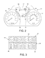
- FIG. 2 is a front view of the combination meter 31 of the first embodiment; the combination meter 31 is installed in the instrument panel (not shown), and is disposed between a tachometer 32 for displaying the engine speed of the engine 3 and a speedometer 33 for displaying the travel speed of the vehicle.
- a temperature gauge 34 for displaying the temperature of the engine coolant, a fuel gauge 35 for displaying the remaining amount of fuel, and a display area 36 for displaying other warnings and indicator illuminates are set in positions between the two meters 32, 33.
- a turn signal indicator lamp, a high-beam indicator lamp, and a shift pattern indicator lamp are disposed in the instrument panel, but are not shown.
- the odometer 37 for displaying the cumulative travel distance of the vehicle and a trip meter 38 for displaying the interval travel distance are disposed above and below in line in the left-right center upper part of the display area 36.
- the odometer 37 and the trip meter 38 calculate and display the travel distance of the vehicle using, e.g., a combination of the axle speed signal and the circumference of the tires.
- FIG. 3 is a front view of the odometer 37 and the trip meter 38 of the first embodiment.
- the odometer 37 is composed of six seven-segment LEDs (number-displaying elements) 39 lined up in the lateral direction for displaying numerical values using seven segments as shown in FIG. 4 . Accordingly, the odometer 37 is capable of displaying six-digit numerical values.
- the trip meter 38 is composed of five seven-segment LEDs (number-displaying elements) 39 lined up in the lateral direction in the same manner as the odometer 37. Accordingly, the trip meter 38 is capable of displaying five-digit numerical values.
- the odometer 37 and the trip meter 38 are disposed in the same position in the lateral direction of the seven-segment LEDs 39 from the ones position.
- the driver can reset the display of the odometer 37 to zero by pressing a reset button 40.
- the trip meter 38 can be switched between trip meters A and B in alternating fashion each time a selector switch 41 is pressed by the driver to display two interval travel distances.
- a character display unit 42 for illuminating one of the characters A and B is disposed on the left end of the trip meter 38.
- the meter controller 29 illuminates the character A when the trip meter A is being displayed, and illuminates the character B with the trip meter B is being displayed.
- the driver can reset the display of the trip meter 38 to zero by pressing the selector switch 41 for a predetermined length of time or greater.
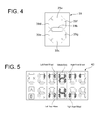
- FIG. 4 is a front view of the seven-segment LED 39 used in the odometer 37 and the trip meter 38.
- the seven-segment LED 39 has three lateral segments 39a, 39b, 39c extending in the lateral direction, and four upright segments 39d, 39e, 39f, 39g extending in the longitudinal direction.
- the upper row lateral segment 39a is positioned in the upper row
- the middle row lateral segment 39b is positioned in the middle row
- the lower row lateral segment 39c is positioned in the lower row.
- the left upper row upright segment 39d is positioned in the left upper row
- the left lower row upright segment 39e is positioned in the left lower row
- the right upper row upright segment 39f is positioned in the right upper row
- the right lower row upright segment 39g is positioned in the right lower row.
- the odometer 37 and the trip meter 38 are sequentially switched between display of the cumulative travel distance and the interval travel distance, display of the state of drive force distribution to each wheel, and display of fuel consumption each time the display selector switch 30 is operated.
- the odometer 37 and the trip meter 38 used in combination are herein below referred to as the drive force distribution display unit 43.
- FIG. 5 is a display example of the drive force distribution display unit 43 during linear forward travel
- FIG. 6 is a display example of the drive force distribution display unit during a right turn.
- the two upper and lower seven-segment LEDs 39 in the lateral center are illuminated in the drive force distribution display unit 43 in an "H"-shape, in other words, five segments excluding the upper row lateral segment 39a and the lower row lateral segment 39c are illuminated to display a symbol than resembles a vehicle body, as shown in FIGS. 5 , 6 .
- the right upper row upright segment 39f of the seven-segment LED 39 adjacent to the left of the upper seven-segment LED 39 displaying the vehicle body, and the left upper row upright segment 39d of the seven-segment LED 39 adjacent to the right of the upper seven-segment LED 39 displaying the vehicle body are illuminated to display a symbol resembling the left and right front wheels 1L, 1R.
- the right lower row upright segment 39g of the seven-segment LED 39 adjacent to the left of the lower seven-segment LED 39 displaying the vehicle body, and the left lower row upright segment 39e of the seven-segment LED 39 adjacent to the right of the lower seven-segment LED 39 displaying the vehicle body, are illuminated to display a symbol resembling the left and right rear wheels 2L, 2R.
- the drive force distribution state of the left front wheel 1L is expressed by the number of display segments (0 to 3), which is the number of segments to be illuminated using the three upper row upright segments that are positioned to the left of the right upper row upright segment 39f and that display the left front wheel 1L.
- the drive force distribution state of the right front wheel 1R is expressed by the number of display (illuminated) segments (0 to 3) using the three upper row upright segments that are positioned to the right of the left upper row upright segment 39d and that display the right front wheel 1R.
- the drive force distribution state of the left rear wheel 2L is expressed by the number of display (illuminated) segments (0 to 3) using the three lower row upright segments that are positioned to the left of the right lower row upright segment 39g and that display the left rear wheel 2L.
- the drive force distribution state of the right rear wheel 2R is expressed by the number of display (illuminated) segments (0 to 3) using the three lower row upright segments that are positioned to the right of the left lower row upright segment 39e and that display the right
- the number of display segments that correspond to the left and right rear wheels 2L, 2R is the same, as shown in FIG. 5 , because the drive force of the left and right rear wheels 2L, 2R is the same during linear forward travel.
- the number of display segments corresponding to the left and right rear wheels 2L, 2R with respect to the total number of display segments is increased in commensurate fashion to the magnitude of the rear wheel distribution.
- the total number of display segments is increased in commensurate fashion to the magnitude of the total drive force of the vehicle.
- the total number of display segments that correspond to each wheel is zero when the vehicle is stopped.
- the number of display segments that correspond to the left rear wheel 2L, which is the turning outside wheel is made greater than the number of display segments that correspond to the right rear wheel 2R, which is the turning inside wheel, because the drive force of the turning outside wheel is greater than the drive force of the turning inside wheel during a turn, as shown in FIG. 6 .
- the difference in the number of display segments corresponding to the left and right rear wheels 2L, 2R is increased in commensurate fashion to the magnitude of the difference in the rear wheel left/right distribution.
- the number of display segments is varied in accordance with the rear wheel distribution and the total drive force of the vehicle.
- FIG. 7 is an example of a segment display pattern during a left turn when there is a difference in the rear, left, and right distribution.
- the 4WD controller 21 divides the total drive force of the vehicle into three drive force regions: high, intermediate, and low. In each drive force region, the rear wheel distribution and the difference in the rear wheel left/right distribution are divided into two regions: high and low, and the segment display pattern is made to be different in each region.
- the rear wheel distribution is not divided only in the case that the motive drive force of the vehicle is low. This is because when the total drive force of the vehicle is low, the rear wheel distribution is very low and the difference in the number of display segments cannot be produced even if the rear wheel distribution were to be divided into high and low levels.
- the display example of FIG. 6 is a segment display pattern for when the total drive force is "intermediate” in FIG. 7 , the rear wheel distribution is "high,” and the difference in the rear wheel left/right distribution is “low.”
- the numerical values of 2R and 2L of FIG. 7 are reversed in the case of a right turn, and a description is therefore omitted.
- the number of display segments corresponding to the right rear wheel 2R is zero except when the total drive force of the vehicle is "high,” the rear wheel distribution is “high,” and the difference in the rear wheel left/right distribution is “low,” but this does not necessarily indicate that the drive force of the right rear wheel 2R is zero.
- the number of display segments is determined in accordance with the difference in the rear wheel left/right distribution, and the number of display segments that correspond to each wheel is a maximum of three.
- the number of display segments of the wheel having a low drive force distribution of the left and right rear wheels 2L, 2R is zero in the case that the three parameters, namely, the total drive force of the vehicle, the rear wheel distribution, and the difference in the rear wheel left/right distribution are expressed using a small number of display segments.
- setting the number of display segments to zero for a wheel having a low drive force distribution of the left and right rear wheels 2L, 2R allows the three parameters, i.e., the total drive force of the vehicle, the rear wheel distribution, and the difference in the rear wheel left/right distribution to be expressed using a greater number of patterns.
- the meter controller 29 displays, as the state of drive force distribution between the wheels, the state of drive force distribution between the left and right front wheels 1L, 1R and the left and right rear wheels 2L, 2R, and the state of drive force distribution between the left and right rear wheels 2L, 2R. Accordingly, the driver can be notified about the state of drive force distribution between the left and right front wheels 1L, 1R and the left and right rear wheels 2L, 2R, and the state of drive force distribution between the left and right rear wheels 2L, 2R when a turn is being made by a four-wheel drive vehicle that can adjust the drive force distribution of the front and rear wheels and the drive force distribution of the left and right rear wheels 2L, 2R as in the first embodiment.
- the meter controller 29 is divided into two regions "high” and “low” in accordance with the drive force distribution of the left and right rear wheels 2L, 2R in relation to the left and right front wheels 1L, 1R, the two regions are further divided into two regions “high” and “low” in accordance with the difference in the rear wheel left/right distribution of the left and right rear wheels 2L, 2R, and the segment display pattern is made to be different in each region.
- the driver can be notified whether rear wheel drive force distribution, which is the minimum required information, is high, and whether the rear wheel left/right distribution is high, using a four-segment display pattern.
- the meter controller 29 divides the total drive force of the vehicle into three drive force regions: high, intermediate, and low; divides the drive force regions "high” and “low” into four regions in accordance with the rear wheel drive force distribution and the difference in the rear wheel left/right distribution as described above; and divides the "low” drive force region into two regions in accordance with the difference in the rear wheel left/right distribution.
- the driver can be notified about the magnitude of the drive force of the vehicle.
- 10 states can be expressed within the restriction of a maximum three display segments corresponding to the wheels.
- the odometer 37 and trip meter 38 which are always provided to a combination meter for a passenger vehicle, are used as the drive force distribution display unit 43. Therefore, a dedicated display device for displaying the drive force distribution state is not required, and manufacturing costs can be minimized in comparison with the case in which a dedicated display device is separately provided.
- the meter controller 29 can display a symbol resembling the vehicle body in a planar shape using two seven-segment LEDs 39 in the center because the two upper and lower seven-segment LEDs 39 in the lateral center are illuminated in an "H"-shape. Therefore, the driver can instantly discern the drive force distribution state of each wheel and visibility can be improved.
- FIG. 8 is another display example during a right turn in the same conditions as FIG. 6 . In other words, this is the segment display pattern in FIG.
Landscapes
- Engineering & Computer Science (AREA)
- Transportation (AREA)
- Mechanical Engineering (AREA)
- Chemical & Material Sciences (AREA)
- Combustion & Propulsion (AREA)
- Automation & Control Theory (AREA)
- Human Computer Interaction (AREA)
- Arrangement And Driving Of Transmission Devices (AREA)
- Instrument Panels (AREA)
Abstract
Description
- The present invention relates to a vehicle display device.
- In a conventional four-wheel drive vehicle in which drive force distribution to the front and rear wheels and drive force distribution to the left and right wheels can be adjusted, there are known distribution display devices for a vehicle in which the state of drive force distribution to the front and rear wheels and the state drive force distribution to the left and right wheels are displayed on a liquid crystal screen (e.g., see Non-Patent Document 1).
- Patent Document 1: 2007 Acura MDX Owner's Manual, ACURA, 2006/08/07, p. 77
- However, in the prior art, there is a problem in that an expensive liquid crystal display is required, which leads to higher cost.
An object of the present invention is to provide a vehicle display device capable of minimizing manufacturing costs. - In the present invention, a number-displaying element having upper-side and lower-side segments arranged vertically in a line are combined to display vehicle information.
- Accordingly, in the present invention, manufacturing costs can be minimized because the vehicle information is displayed using a segment display that is less expensive than a liquid crystal screen.
-
- [
FIG. 1 ] is a block diagram of the vehicle drive system in a four-wheel drive vehicle of the first embodiment; - [
FIG. 2 ] is a front view of thecombination meter 31 of the first embodiment; - [
FIG. 3 is a front view of theodometer 37 and thetrip meter 38 of the first embodiment; - [
FIG. 4 ] is a front view of the seven-segment LED 39; - [
FIG. 5 ] is a display example of the drive forcedistribution display unit 43 during linear forward travel; - [
FIG. 6 ] is a display example of the drive forcedistribution display unit 43 during a right turn; - [
FIG. 7 ] is an example of a segment display pattern when there is a difference in the rear, left, and right distribution during a left turn; and - [
FIG. 8 ] is a display example of the drive forcedistribution display unit 43 during a right turn in another embodiment. -
- 21: 4WD controller
- 29: Meter controller (display control means)
- 30: Display selector switch
- 31: Combination meter
- 37: Odometer (upper-side segment display)
- 38: Trip meter (lower-side segment display)
- 39: Segment LED (number-displaying element)
- 39a: Upper level lateral segment
- 39b: Middle level lateral segment
- 39c: Lower level lateral segment
- 39d: Left upper level upright segment
- 39e: Left lower level upright segment
- 39f: Right upper level upright segment
- 39g: Right lower level upright segment
- 43: Drive force distribution display unit
- Embodiments for implementing the vehicle display device of the present invention are described below with reference to the embodiments in the drawings.
-
Fig. 1 is a block diagram of the vehicle drive system in a four-wheel drive vehicle of the first embodiment. - The four-wheel drive vehicle of the first embodiment changes the speed of the rotational power from the
engine 3 using a transmission (a transaxle including adifferential device 4a) 4, directs the rotational power to the left and rightfront wheels right axle shafts front wheels - After the speed has been changed by the
transmission 4, a portion of the drive force (torque) directed to the left and rightfront wheels transfer case 6, directed to the left and rightrear wheels rear wheels - The
transfer case 6 has a bevel gear assembly composed of aninput hypoid gear 6a and anoutput hypoid gear 6b. Theinput hypoid gear 6a is configured so as to rotate together with a differential gear case, which is an input rotation member of thedifferential device 4a. The front end of apropeller shaft 7 is coupled to theoutput hypoid gear 6b, and thepropeller shaft 7 extends rearward toward the left and right rear wheel driveforce distribution unit 8. Thetransfer case 6 determines the gear ratio of the bevel gear assembly composed of theinput hypoid gear 6a and theoutput hypoid gear 6b so that a portion of the drive force directed to the left and rightfront wheels propeller shaft 7 at increased speed. - The speed-increasing rotational power to the
propeller shaft 7 is distributed and outputted to the left and rightrear wheels force distribution unit 8. Accordingly, the left and right rear wheel driveforce distribution unit 8 has acenter shaft 10 disposed between theaxle shafts rear wheels shafts
The left and right rear wheel driveforce distribution unit 8 furthermore has: a leftrear wheel clutch 11L disposed between thecenter shaft 10 and theaxle shaft 9L and used for coupling and controlling theshafts rear wheel clutch 11R disposed between thecenter shaft 10 and theaxle shaft 9R and used for coupling and controlling theshafts - The interval between the
center shaft 10 and the rear end of thepropeller shaft 7 extending from thetransfer case 6 in the rearward direction of the vehicle is drivably coupled via a bevel gear-typefinal reduction gear 12 composed of aninput hypoid gear 12a and anoutput hypoid gear 12b. The reduction ratio of thefinal reduction gear 12 is a gear ratio that causes a portion of the drive force directed to the left and rightfront wheels center shaft 10 in relation to the above-described speed-increasing gear ratio (speed-increasing gear ratio of the bevel gear assembly composed of thehypoid gear 6a and theoutput hypoid gear 6b) of thetransfer case 6; and in the first embodiment, sets the total gear ratio of thetransfer case 6 and thefinal reduction gear 12 so that thecenter shaft 10 is rotated with increased speed with respect to the left and rightfront wheels - In the wheel drive system of a four-wheel drive vehicle of the first embodiment, the rotational drive force from the
engine 3 arrives at the left and rightfront wheels front wheels front wheels center shaft 10 from thetransfer case 6 in sequence via thepropeller shaft 7 and thefinal reduction gear 12; and the left and rightrear wheels clutches clutches front wheels rear wheels - In the four-wheel drive vehicle of the first embodiment, an object is to improve the start performance and the acceleration performance of the vehicle, and the front and rear wheel drive force distribution is controlled via the total engaging force control of the left
rear wheel clutch 11L and the rightrear wheel clutch 11R. Another object is to improve the turning performance and stabilize the turning behavior of a vehicle, and the left and right wheel drive force distribution is controlled via the total engaging force control of the leftrear wheel clutch 11L and the rightrear wheel clutch 11R. Accordingly, the engaging force control system of the leftrear wheel clutch 11L and the rightrear wheel clutch 11R is as described below.
The leftrear wheel clutch 11L and the rightrear wheel clutch 11R are electromagnetic clutches in which the engaging force is determined in accordance with the supplied electric current, and the supply of electric current to theclutches clutches rear wheels controller 21, whereby the front and rear wheel drive force distribution and the left and right wheel drive force distribution are controlled. - In order to compute the above-described target drive force TcL of the left
rear wheel 2L and the target drive force TcR of the rightrear wheel 2R, the4WD controller 21 receives input of a signal from avehicle speed sensor 22 for detecting the vehicle speed VSP, a signal from ayaw rate sensor 23 for detecting the yaw rate φ around the center of the vertical axis that passes through the center of gravity of the vehicle, a signal from asteering angle sensor 24 for detecting the steering angle θ of the steering wheel, a signal from anengine torque computer 25 for computing the output torque Te of theengine 3, a signal from theengine speed sensor 26 for detecting the engine speed Ne, a signal from theaccelerator position sensor 27 for detecting the accelerator position APO, which is the amount of pressure on the accelerator pedal, and a transmissiongear ratio sensor 28 for detecting the gear ratio γ currently selected by thetransmission 4.
The4WD controller 21 calculates the total drive force of the vehicle based on the above input information, and calculates the rear wheel distribution (the drive force distribution of the left and rightrear wheels rear wheel clutch 11L and the rightrear wheel clutch 11R is electronically controlled so that the drive force of the left and rightrear wheels - The
4WD controller 21 computes a segment illuminating pattern for displaying the state of drive force distribution between the front and rear wheels and the left and right rear wheels on a later-described odometer (upper-side segment display) 37 and trip meter (lower-side segment display) 38 arranged in acombination meter 31, on the basis of the calculated total drive force of the vehicle, rear wheel distribution, and rear wheel right left distribution difference; and sends the computation results to the meter controller (display control means) 29 using a CAN communication line (not shown). Themeter controller 29 switches the display content of theodometer 37 and thetrip meter 38 sequentially between the distance (cumulative travel distance and interval travel distance) display, the drive force distribution state display, and the fuel consumption display, each time thedisplay selector switch 30 is operated by the driver. Here, it is also possible to use a configuration in which, in addition to fuel consumption, one or more other items of vehicle information are selected for display. Such a configuration is described below. Theselector switch 30 is disposed on, e.g., the steering wheel (not shown), the instrument panel, or in another position that allows operation by the driver while the vehicle is traveling. -
FIG. 2 is a front view of thecombination meter 31 of the first embodiment; thecombination meter 31 is installed in the instrument panel (not shown), and is disposed between atachometer 32 for displaying the engine speed of theengine 3 and aspeedometer 33 for displaying the travel speed of the vehicle. Atemperature gauge 34 for displaying the temperature of the engine coolant, afuel gauge 35 for displaying the remaining amount of fuel, and adisplay area 36 for displaying other warnings and indicator illuminates are set in positions between the twometers - The
odometer 37 for displaying the cumulative travel distance of the vehicle and atrip meter 38 for displaying the interval travel distance are disposed above and below in line in the left-right center upper part of thedisplay area 36. Theodometer 37 and thetrip meter 38 calculate and display the travel distance of the vehicle using, e.g., a combination of the axle speed signal and the circumference of the tires.
FIG. 3 is a front view of theodometer 37 and thetrip meter 38 of the first embodiment. Theodometer 37 is composed of six seven-segment LEDs (number-displaying elements) 39 lined up in the lateral direction for displaying numerical values using seven segments as shown inFIG. 4 . Accordingly, theodometer 37 is capable of displaying six-digit numerical values. Thetrip meter 38 is composed of five seven-segment LEDs (number-displaying elements) 39 lined up in the lateral direction in the same manner as theodometer 37. Accordingly, thetrip meter 38 is capable of displaying five-digit numerical values. Theodometer 37 and thetrip meter 38 are disposed in the same position in the lateral direction of the seven-segment LEDs 39 from the ones position.
The driver can reset the display of theodometer 37 to zero by pressing areset button 40. Thetrip meter 38 can be switched between trip meters A and B in alternating fashion each time aselector switch 41 is pressed by the driver to display two interval travel distances. Acharacter display unit 42 for illuminating one of the characters A and B is disposed on the left end of thetrip meter 38. Themeter controller 29 illuminates the character A when the trip meter A is being displayed, and illuminates the character B with the trip meter B is being displayed. The driver can reset the display of thetrip meter 38 to zero by pressing theselector switch 41 for a predetermined length of time or greater. -
FIG. 4 is a front view of the seven-segment LED 39 used in theodometer 37 and thetrip meter 38. The seven-segment LED 39 has threelateral segments upright segments row lateral segment 39a is positioned in the upper row, the middlerow lateral segment 39b is positioned in the middle row, and the lowerrow lateral segment 39c is positioned in the lower row. The left upper rowupright segment 39d is positioned in the left upper row, the left lower rowupright segment 39e is positioned in the left lower row, the right upper rowupright segment 39f is positioned in the right upper row, and the right lowerrow upright segment 39g is positioned in the right lower row.
As described above, theodometer 37 and thetrip meter 38 are sequentially switched between display of the cumulative travel distance and the interval travel distance, display of the state of drive force distribution to each wheel, and display of fuel consumption each time thedisplay selector switch 30 is operated. Five of the seven-segment LEDs 39 constituting thetrip meter 38 and five of the seven-segment LEDs 39 from the right of the six seven-segment LEDs 39 constituting theodometer 37, totaling 10 seven-segment LEDs 39, are used as the display for the drive force distribution state. Theodometer 37 and thetrip meter 38 used in combination are herein below referred to as the drive forcedistribution display unit 43. -
FIG. 5 is a display example of the drive forcedistribution display unit 43 during linear forward travel, andFIG. 6 is a display example of the drive force distribution display unit during a right turn. The two upper and lower seven-segment LEDs 39 in the lateral center are illuminated in the drive forcedistribution display unit 43 in an "H"-shape, in other words, five segments excluding the upperrow lateral segment 39a and the lowerrow lateral segment 39c are illuminated to display a symbol than resembles a vehicle body, as shown inFIGS. 5 ,6 . Also, the right upper rowupright segment 39f of the seven-segment LED 39 adjacent to the left of the upper seven-segment LED 39 displaying the vehicle body, and the left upper rowupright segment 39d of the seven-segment LED 39 adjacent to the right of the upper seven-segment LED 39 displaying the vehicle body are illuminated to display a symbol resembling the left and rightfront wheels row upright segment 39g of the seven-segment LED 39 adjacent to the left of the lower seven-segment LED 39 displaying the vehicle body, and the left lower rowupright segment 39e of the seven-segment LED 39 adjacent to the right of the lower seven-segment LED 39 displaying the vehicle body, are illuminated to display a symbol resembling the left and rightrear wheels - The drive force distribution state of the
left front wheel 1L is expressed by the number of display segments (0 to 3), which is the number of segments to be illuminated using the three upper row upright segments that are positioned to the left of the right upper rowupright segment 39f and that display theleft front wheel 1L. The drive force distribution state of theright front wheel 1R is expressed by the number of display (illuminated) segments (0 to 3) using the three upper row upright segments that are positioned to the right of the left upper rowupright segment 39d and that display theright front wheel 1R. The drive force distribution state of the leftrear wheel 2L is expressed by the number of display (illuminated) segments (0 to 3) using the three lower row upright segments that are positioned to the left of the right lowerrow upright segment 39g and that display the leftrear wheel 2L. The drive force distribution state of the rightrear wheel 2R is expressed by the number of display (illuminated) segments (0 to 3) using the three lower row upright segments that are positioned to the right of the left lower rowupright segment 39e and that display the rightrear wheel 2R. - For example, the number of display segments that correspond to the left and right
rear wheels FIG. 5 , because the drive force of the left and rightrear wheels rear wheels
With reference to the left and rightrear wheels rear wheel 2L, which is the turning outside wheel, is made greater than the number of display segments that correspond to the rightrear wheel 2R, which is the turning inside wheel, because the drive force of the turning outside wheel is greater than the drive force of the turning inside wheel during a turn, as shown inFIG. 6 . At this time, the difference in the number of display segments corresponding to the left and rightrear wheels -
FIG. 7 is an example of a segment display pattern during a left turn when there is a difference in the rear, left, and right distribution. The4WD controller 21 divides the total drive force of the vehicle into three drive force regions: high, intermediate, and low. In each drive force region, the rear wheel distribution and the difference in the rear wheel left/right distribution are divided into two regions: high and low, and the segment display pattern is made to be different in each region. Here, the rear wheel distribution is not divided only in the case that the motive drive force of the vehicle is low. This is because when the total drive force of the vehicle is low, the rear wheel distribution is very low and the difference in the number of display segments cannot be produced even if the rear wheel distribution were to be divided into high and low levels.
Therefore, it is apparent, for example, that the display example ofFIG. 6 is a segment display pattern for when the total drive force is "intermediate" inFIG. 7 , the rear wheel distribution is "high," and the difference in the rear wheel left/right distribution is "low."
The numerical values of 2R and 2L ofFIG. 7 are reversed in the case of a right turn, and a description is therefore omitted. - Here, in the display pattern shown in
FIG. 7 , the number of display segments corresponding to the rightrear wheel 2R is zero except when the total drive force of the vehicle is "high," the rear wheel distribution is "high," and the difference in the rear wheel left/right distribution is "low," but this does not necessarily indicate that the drive force of the rightrear wheel 2R is zero. In the first embodiment, the number of display segments is determined in accordance with the difference in the rear wheel left/right distribution, and the number of display segments that correspond to each wheel is a maximum of three. Therefore, the number of display segments of the wheel having a low drive force distribution of the left and rightrear wheels rear wheels - Next, the effect of the first embodiment will be described.
Effects such as those described below can be obtained in accordance with the drive force distribution display device of the first embodiment described above. - (1) The present invention is provided with an
odometer 37 andtrip meter 38 arranged vertically in a line, and ameter controller 29 for displaying a vehicle body using the two upper and lower seven-segment LEDs 39 near the lateral center between theodometer 37 and thetrip meter 38, and displaying the state of drive force distribution between the wheels (the state of drive force distribution between the front and rear wheels and the state of drive force distribution between the left and right wheels) using the seven-segments LED 39 to the left and right of the two upper and lower seven-segment LEDs 39 that display the vehicle body. - (2) The
meter controller 29 displays, as the state of drive force distribution between the wheels, the state of drive force distribution between the left and rightfront wheels rear wheels rear wheels front wheels rear wheels rear wheels rear wheels - (3) The
meter controller 29 is divided into two regions "high" and "low" in accordance with the drive force distribution of the left and rightrear wheels front wheels rear wheels - (4) The
meter controller 29 divides the total drive force of the vehicle into three drive force regions: high, intermediate, and low; divides the drive force regions "high" and "low" into four regions in accordance with the rear wheel drive force distribution and the difference in the rear wheel left/right distribution as described above; and divides the "low" drive force region into two regions in accordance with the difference in the rear wheel left/right distribution. In addition to the magnitude of the rear wheel drive force distribution and the magnitude of the difference in the rear wheel left/right distribution, the driver can be notified about the magnitude of the drive force of the vehicle. Also, 10 states can be expressed within the restriction of a maximum three display segments corresponding to the wheels. - (5) The
odometer 37 andtrip meter 38, which are always provided to a combination meter for a passenger vehicle, are used as the drive forcedistribution display unit 43. Therefore, a dedicated display device for displaying the drive force distribution state is not required, and manufacturing costs can be minimized in comparison with the case in which a dedicated display device is separately provided. - (6) The
odometer 37 and thetrip meter 38 are sequentially switched between the distance display, the drive force distribution state display, and the fuel consumption display, each time thedisplay selector switch 30 is operated. Therefore, the driver can switch to the drive force distribution state display only when necessary, and can elect not to display the drive force distribution state when not required. - The
meter controller 29 can display a symbol resembling the vehicle body in a planar shape using two seven-segment LEDs 39 in the center because the two upper and lower seven-segment LEDs 39 in the lateral center are illuminated in an "H"-shape. Therefore, the driver can instantly discern the drive force distribution state of each wheel and visibility can be improved. - (8) Among the upper row upright segments of the two seven-
segment LEDs segment LED 39 illuminated in an "H"-shape, the upper row upright segments that are on the sides near the seven-segment LED 39 illuminated in an "H"-shape are illuminated by themeter controller 29 so that the left and right front wheels are displayed, and among the lower row upright segments of the two seven-segment LEDs segment LED 39 illuminated in an "H"-shape, the lower row upright segments that are on the sides near the seven-segment LED 39 illuminated in an "H"-shape are illuminated by themeter controller 29 so that the left and right rear wheels are displayed. A symbol resembling the vehicle body in a planar shape using two seven-segment LEDs 39 can thereby be displayed in the center. Accordingly, improvement in the visibility and design can be ensured. - A preferred embodiment of the present invention was described above using an example, but the specific configuration of the present invention is not limited to the example; the present invention encompasses design modifications and the like that do not depart from the spirit of the invention.
For example, it is possible to display only the vehicle body in the center of the drive forcedistribution display unit 43 and to omit display of the wheels, as shown inFIG. 8 . Also, the segments to be displayed are not limited to the upright segments, and it is also possible to display rectangles such as those inFIG. 8 as a single symbol.FIG. 8 is another display example during a right turn in the same conditions asFIG. 6 . In other words, this is the segment display pattern inFIG. 7 for a drive force that is "intermediate," a rear wheel distribution that is "high," and a difference in the rear wheel left/right distribution that is "low."
In the first embodiment, an example was described in which the odometer and trip meter displays are switched from distance display to drive force distribution state display using the switch operation by the driver as a trigger. However, it is also possible to use a configuration in which the switch is automatically made from distance display to drive force distribution state display using a change in the state of the drive force distribution to the front and rear wheels and/or the state of the drive force distribution to the left and right wheels as a trigger.
Claims (9)
- A vehicle display device characterized in being provided with:an upper-side segment display comprising three or more number-displaying elements arranged in a line in a lateral direction for displaying numerical values using a plurality of segments, the upper-side segment display being disposed in a vehicle instrument panel;a lower-side segment display comprising three or more number-displaying elements arranged in a line in the lateral direction for displaying numerical values using a plurality of segments, the lower-side segment display being disposed below the upper-side segment display; anddisplay control means for combining the number-displaying elements in the upper-side and lower-side segment displays and displaying vehicle information.
- The vehicle display device according to claim 1, characterized in that
the display control means displays a vehicle body using the two upper and lower number-displaying elements near the lateral center in the upper-side and lower-side segment displays, and displays a state of drive force distribution between wheels using left and right number-displaying elements of the upper and lower number-displaying elements that show the vehicle body. - The vehicle display device according to claim 2, characterized in that
the display control means displays the state of drive force distribution between main drive wheels and auxiliary drive wheels and the state of drive force distribution between left and right wheels as the state of drive force distribution between the wheels. - The vehicle display device according to claim 2 or 3, characterized in that
the display control means divides the state of drive force distribution between the wheels into a plurality of regions in accordance with the drive force distribution of the auxiliary drive wheels with respect to the main drive wheels and the difference in the drive force distribution between the left and right wheels, and causes the segment display pattern of the number-displaying elements for displaying the state of drive force distribution between the wheels to be different in each of the regions. - The vehicle display device according to claim 4, characterized in that
the display control means divides the state of drive force distribution between the wheels into a plurality of drive force regions in accordance with a total drive force distribution of a vehicle, and divides the drive force regions into a plurality of regions in accordance with the drive force distribution to the auxiliary wheels with respect to the main drive wheels and the difference in the drive force distribution of the left and right wheels. - The vehicle display device according to any of claims 2 to 5, characterized in that
the upper-side and lower-side segment displays are displays for displaying one or more vehicle states, and are sequentially switched between display of the one or more vehicle states and display of the drive force distribution state each time a display selector switch is operated by the driver. - The vehicle display device according to claim 6, characterized in that
one of the upper-side and lower-side segment displays is an odometer for displaying a cumulative travel distance as predetermined vehicle information, and the other of the upper-side and lower-side segment displays is a trip meter for displaying an interval travel distance as predetermined vehicle information. - The vehicle display device according to any of claims 2 to 7, characterized in that
the number-displaying elements are seven-segment LEDs, and
the display control means illuminates two upper and lower seven-segment LEDs near a lateral center in an "H"-shape to display the vehicle body. - The vehicle display device according to claim 8, characterized in that
among upper row upright segments of the two seven-segment LEDs laterally adjacent to the upper seven-segment LED illuminated in an "H"-shape, the upper row upright segments that are on sides near the seven-segment LED illuminated in an "H"-shape are illuminated by the display control means so that the left and right front wheels are displayed; and, among the lower row upright segments of the two seven-segment LEDs laterally adjacent to the lower seven-segment LED illuminated in an "H"-shape, the lower row upright segments that are on the sides near the seven-segment LED illuminated in an "H"-shape are illuminated by the display control means so that the left and right rear wheels are displayed.
Applications Claiming Priority (2)
| Application Number | Priority Date | Filing Date | Title |
|---|---|---|---|
| JP2010156663 | 2010-07-09 | ||
| PCT/JP2011/065389 WO2012005255A1 (en) | 2010-07-09 | 2011-07-05 | Vehicle display device |
Publications (3)
| Publication Number | Publication Date |
|---|---|
| EP2591943A1 true EP2591943A1 (en) | 2013-05-15 |
| EP2591943A4 EP2591943A4 (en) | 2017-12-20 |
| EP2591943B1 EP2591943B1 (en) | 2019-08-21 |
Family
ID=45441233
Family Applications (1)
| Application Number | Title | Priority Date | Filing Date |
|---|---|---|---|
| EP11803589.8A Active EP2591943B1 (en) | 2010-07-09 | 2011-07-05 | Vehicle display device |
Country Status (5)
| Country | Link |
|---|---|
| US (1) | US8909423B2 (en) |
| EP (1) | EP2591943B1 (en) |
| JP (1) | JP5440703B2 (en) |
| CN (1) | CN102971177B (en) |
| WO (1) | WO2012005255A1 (en) |
Families Citing this family (12)
| Publication number | Priority date | Publication date | Assignee | Title |
|---|---|---|---|---|
| WO2014080459A1 (en) * | 2012-11-20 | 2014-05-30 | トヨタ自動車株式会社 | Torque display device and vehicle comprising same |
| JP6243656B2 (en) * | 2013-08-06 | 2017-12-06 | 株式会社Subaru | Automotive torque distribution sound presentation device |
| JP6244135B2 (en) * | 2013-08-09 | 2017-12-06 | 矢崎総業株式会社 | Meter |
| JP6197524B2 (en) * | 2013-09-19 | 2017-09-20 | トヨタ自動車株式会社 | Control device for four-wheel drive vehicle |
| FR3020701A1 (en) * | 2014-05-05 | 2015-11-06 | Jean Francois Laurent | DISTANCE MEASUREMENT MODULE WITH PREDICTIVE SIGNAL INTERPOLATION FOR EQUIPPING A VEHICLE |
| CN104477116B (en) * | 2014-12-04 | 2016-10-26 | 重庆长安汽车股份有限公司 | A kind of four-wheel drive cars moment of torsion Real time dynamic display system and method |
| CN104842793A (en) * | 2014-12-18 | 2015-08-19 | 北汽福田汽车股份有限公司 | Driving-torque display method and system thereof for automobiles |
| JP6350595B2 (en) * | 2016-05-26 | 2018-07-04 | トヨタ自動車株式会社 | Meter display control device |
| JP7088926B2 (en) * | 2017-06-29 | 2022-06-21 | 本田技研工業株式会社 | Vehicle instruments |
| US10604014B1 (en) * | 2019-03-05 | 2020-03-31 | Honda Motors Co., Ltd. | Tachometer display system and method for display |
| CN115916610A (en) * | 2020-04-21 | 2023-04-04 | 北极星工业有限公司 | Systems and methods for operating all terrain vehicles |
| CN113928117B (en) * | 2021-03-25 | 2023-04-14 | 长城汽车股份有限公司 | Four-wheel drive vehicle front and rear axle torque display method and system |
Family Cites Families (8)
| Publication number | Priority date | Publication date | Assignee | Title |
|---|---|---|---|---|
| JPH0641251B2 (en) * | 1985-04-22 | 1994-06-01 | マツダ株式会社 | Torque distribution display device for four-wheel drive vehicle |
| JPH09146478A (en) * | 1995-11-20 | 1997-06-06 | Fenwall Controls Of Japan Ltd | Display method by seven segment |
| US7145442B1 (en) * | 2003-10-14 | 2006-12-05 | Yu Hei Sunny Wai | Vehicle operation display system |
| JP2007322343A (en) | 2006-06-05 | 2007-12-13 | Calsonic Kansei Corp | Vehicular instrument |
| JP5040366B2 (en) | 2007-03-02 | 2012-10-03 | トヨタ自動車株式会社 | Vehicle control device |
| JP4471132B2 (en) | 2007-07-24 | 2010-06-02 | 三菱自動車工業株式会社 | Turning behavior display device |
| JP2010102089A (en) | 2008-10-23 | 2010-05-06 | Mitsutoyo Corp | Display device |
| CN201463914U (en) * | 2009-05-07 | 2010-05-12 | 纽贝耳汽车(杭州)有限公司 | Combined meter of pure electric vehicle |
-
2011
- 2011-07-05 WO PCT/JP2011/065389 patent/WO2012005255A1/en not_active Ceased
- 2011-07-05 CN CN201180033431.2A patent/CN102971177B/en not_active Expired - Fee Related
- 2011-07-05 EP EP11803589.8A patent/EP2591943B1/en active Active
- 2011-07-05 JP JP2012523882A patent/JP5440703B2/en not_active Expired - Fee Related
- 2011-07-05 US US13/700,689 patent/US8909423B2/en active Active
Non-Patent Citations (1)
| Title |
|---|
| See references of WO2012005255A1 * |
Also Published As
| Publication number | Publication date |
|---|---|
| CN102971177B (en) | 2015-06-10 |
| JP5440703B2 (en) | 2014-03-12 |
| CN102971177A (en) | 2013-03-13 |
| EP2591943A4 (en) | 2017-12-20 |
| JPWO2012005255A1 (en) | 2013-09-05 |
| WO2012005255A1 (en) | 2012-01-12 |
| US20130079986A1 (en) | 2013-03-28 |
| EP2591943B1 (en) | 2019-08-21 |
| US8909423B2 (en) | 2014-12-09 |
Similar Documents
| Publication | Publication Date | Title |
|---|---|---|
| EP2591943B1 (en) | Vehicle display device | |
| JP5315174B2 (en) | Torque display device for vehicle | |
| JP4648681B2 (en) | Vehicle display device | |
| CN105555577B (en) | Control system for four-wheel drive vehicle | |
| JP4637546B2 (en) | Vehicle display device | |
| US7726255B2 (en) | Display device for vehicle | |
| CN101462552B (en) | Pivoting display device | |
| CN105793095A (en) | Display control system for vehicle | |
| US10500956B2 (en) | Moveable display screen | |
| JP2025089549A (en) | Vehicle meter unit | |
| JP5073362B2 (en) | Vehicle instrument | |
| JP2006273114A (en) | Display device for vehicle with automatic transmission | |
| JP7446669B2 (en) | distribution display device | |
| TWI762174B (en) | Display device for vehicle | |
| JP2011017723A (en) | Display device for vehicle | |
| CN110171293B (en) | Vehicle with a steering wheel | |
| JP6380293B2 (en) | Vehicle display device | |
| JP2022168648A (en) | Vehicle traveling mode switching device and display device thereof | |
| JP7224721B2 (en) | Distribution status display device | |
| JP2014083924A (en) | Display device | |
| JP4966093B2 (en) | Work vehicle | |
| JP4421449B2 (en) | Display device | |
| EP3796295B1 (en) | Display device, and a straddled vehicle with the display device | |
| JP2019018718A (en) | Vehicular display system | |
| JP4874869B2 (en) | Work vehicle |
Legal Events
| Date | Code | Title | Description |
|---|---|---|---|
| PUAI | Public reference made under article 153(3) epc to a published international application that has entered the european phase |
Free format text: ORIGINAL CODE: 0009012 |
|
| 17P | Request for examination filed |
Effective date: 20130211 |
|
| AK | Designated contracting states |
Kind code of ref document: A1 Designated state(s): AL AT BE BG CH CY CZ DE DK EE ES FI FR GB GR HR HU IE IS IT LI LT LU LV MC MK MT NL NO PL PT RO RS SE SI SK SM TR |
|
| DAX | Request for extension of the european patent (deleted) | ||
| RIC1 | Information provided on ipc code assigned before grant |
Ipc: B60W 50/14 20120101ALI20171108BHEP Ipc: B60W 10/06 20060101ALI20171108BHEP Ipc: B60W 10/02 20060101ALI20171108BHEP Ipc: B60K 37/02 20060101ALI20171108BHEP Ipc: B60K 35/00 20060101AFI20171108BHEP Ipc: B60W 30/18 20120101ALI20171108BHEP Ipc: B60W 10/08 20060101ALI20171108BHEP Ipc: B60W 20/00 20160101ALI20171108BHEP |
|
| RA4 | Supplementary search report drawn up and despatched (corrected) |
Effective date: 20171117 |
|
| GRAP | Despatch of communication of intention to grant a patent |
Free format text: ORIGINAL CODE: EPIDOSNIGR1 |
|
| STAA | Information on the status of an ep patent application or granted ep patent |
Free format text: STATUS: GRANT OF PATENT IS INTENDED |
|
| INTG | Intention to grant announced |
Effective date: 20190411 |
|
| GRAS | Grant fee paid |
Free format text: ORIGINAL CODE: EPIDOSNIGR3 |
|
| GRAA | (expected) grant |
Free format text: ORIGINAL CODE: 0009210 |
|
| STAA | Information on the status of an ep patent application or granted ep patent |
Free format text: STATUS: THE PATENT HAS BEEN GRANTED |
|
| AK | Designated contracting states |
Kind code of ref document: B1 Designated state(s): AL AT BE BG CH CY CZ DE DK EE ES FI FR GB GR HR HU IE IS IT LI LT LU LV MC MK MT NL NO PL PT RO RS SE SI SK SM TR |
|
| REG | Reference to a national code |
Ref country code: GB Ref legal event code: FG4D |
|
| REG | Reference to a national code |
Ref country code: CH Ref legal event code: EP |
|
| REG | Reference to a national code |
Ref country code: DE Ref legal event code: R096 Ref document number: 602011061465 Country of ref document: DE |
|
| REG | Reference to a national code |
Ref country code: AT Ref legal event code: REF Ref document number: 1169332 Country of ref document: AT Kind code of ref document: T Effective date: 20190915 |
|
| REG | Reference to a national code |
Ref country code: IE Ref legal event code: FG4D |
|
| REG | Reference to a national code |
Ref country code: LT Ref legal event code: MG4D |
|
| REG | Reference to a national code |
Ref country code: NL Ref legal event code: MP Effective date: 20190821 |
|
| PG25 | Lapsed in a contracting state [announced via postgrant information from national office to epo] |
Ref country code: PT Free format text: LAPSE BECAUSE OF FAILURE TO SUBMIT A TRANSLATION OF THE DESCRIPTION OR TO PAY THE FEE WITHIN THE PRESCRIBED TIME-LIMIT Effective date: 20191223 Ref country code: NO Free format text: LAPSE BECAUSE OF FAILURE TO SUBMIT A TRANSLATION OF THE DESCRIPTION OR TO PAY THE FEE WITHIN THE PRESCRIBED TIME-LIMIT Effective date: 20191121 Ref country code: BG Free format text: LAPSE BECAUSE OF FAILURE TO SUBMIT A TRANSLATION OF THE DESCRIPTION OR TO PAY THE FEE WITHIN THE PRESCRIBED TIME-LIMIT Effective date: 20191121 Ref country code: NL Free format text: LAPSE BECAUSE OF FAILURE TO SUBMIT A TRANSLATION OF THE DESCRIPTION OR TO PAY THE FEE WITHIN THE PRESCRIBED TIME-LIMIT Effective date: 20190821 Ref country code: FI Free format text: LAPSE BECAUSE OF FAILURE TO SUBMIT A TRANSLATION OF THE DESCRIPTION OR TO PAY THE FEE WITHIN THE PRESCRIBED TIME-LIMIT Effective date: 20190821 Ref country code: LT Free format text: LAPSE BECAUSE OF FAILURE TO SUBMIT A TRANSLATION OF THE DESCRIPTION OR TO PAY THE FEE WITHIN THE PRESCRIBED TIME-LIMIT Effective date: 20190821 Ref country code: SE Free format text: LAPSE BECAUSE OF FAILURE TO SUBMIT A TRANSLATION OF THE DESCRIPTION OR TO PAY THE FEE WITHIN THE PRESCRIBED TIME-LIMIT Effective date: 20190821 Ref country code: HR Free format text: LAPSE BECAUSE OF FAILURE TO SUBMIT A TRANSLATION OF THE DESCRIPTION OR TO PAY THE FEE WITHIN THE PRESCRIBED TIME-LIMIT Effective date: 20190821 |
|
| PG25 | Lapsed in a contracting state [announced via postgrant information from national office to epo] |
Ref country code: AL Free format text: LAPSE BECAUSE OF FAILURE TO SUBMIT A TRANSLATION OF THE DESCRIPTION OR TO PAY THE FEE WITHIN THE PRESCRIBED TIME-LIMIT Effective date: 20190821 Ref country code: GR Free format text: LAPSE BECAUSE OF FAILURE TO SUBMIT A TRANSLATION OF THE DESCRIPTION OR TO PAY THE FEE WITHIN THE PRESCRIBED TIME-LIMIT Effective date: 20191122 Ref country code: RS Free format text: LAPSE BECAUSE OF FAILURE TO SUBMIT A TRANSLATION OF THE DESCRIPTION OR TO PAY THE FEE WITHIN THE PRESCRIBED TIME-LIMIT Effective date: 20190821 Ref country code: IS Free format text: LAPSE BECAUSE OF FAILURE TO SUBMIT A TRANSLATION OF THE DESCRIPTION OR TO PAY THE FEE WITHIN THE PRESCRIBED TIME-LIMIT Effective date: 20191221 Ref country code: LV Free format text: LAPSE BECAUSE OF FAILURE TO SUBMIT A TRANSLATION OF THE DESCRIPTION OR TO PAY THE FEE WITHIN THE PRESCRIBED TIME-LIMIT Effective date: 20190821 Ref country code: ES Free format text: LAPSE BECAUSE OF FAILURE TO SUBMIT A TRANSLATION OF THE DESCRIPTION OR TO PAY THE FEE WITHIN THE PRESCRIBED TIME-LIMIT Effective date: 20190821 |
|
| REG | Reference to a national code |
Ref country code: AT Ref legal event code: MK05 Ref document number: 1169332 Country of ref document: AT Kind code of ref document: T Effective date: 20190821 |
|
| PG25 | Lapsed in a contracting state [announced via postgrant information from national office to epo] |
Ref country code: TR Free format text: LAPSE BECAUSE OF FAILURE TO SUBMIT A TRANSLATION OF THE DESCRIPTION OR TO PAY THE FEE WITHIN THE PRESCRIBED TIME-LIMIT Effective date: 20190821 |
|
| PG25 | Lapsed in a contracting state [announced via postgrant information from national office to epo] |
Ref country code: IT Free format text: LAPSE BECAUSE OF FAILURE TO SUBMIT A TRANSLATION OF THE DESCRIPTION OR TO PAY THE FEE WITHIN THE PRESCRIBED TIME-LIMIT Effective date: 20190821 Ref country code: RO Free format text: LAPSE BECAUSE OF FAILURE TO SUBMIT A TRANSLATION OF THE DESCRIPTION OR TO PAY THE FEE WITHIN THE PRESCRIBED TIME-LIMIT Effective date: 20190821 Ref country code: DK Free format text: LAPSE BECAUSE OF FAILURE TO SUBMIT A TRANSLATION OF THE DESCRIPTION OR TO PAY THE FEE WITHIN THE PRESCRIBED TIME-LIMIT Effective date: 20190821 Ref country code: PL Free format text: LAPSE BECAUSE OF FAILURE TO SUBMIT A TRANSLATION OF THE DESCRIPTION OR TO PAY THE FEE WITHIN THE PRESCRIBED TIME-LIMIT Effective date: 20190821 Ref country code: EE Free format text: LAPSE BECAUSE OF FAILURE TO SUBMIT A TRANSLATION OF THE DESCRIPTION OR TO PAY THE FEE WITHIN THE PRESCRIBED TIME-LIMIT Effective date: 20190821 Ref country code: AT Free format text: LAPSE BECAUSE OF FAILURE TO SUBMIT A TRANSLATION OF THE DESCRIPTION OR TO PAY THE FEE WITHIN THE PRESCRIBED TIME-LIMIT Effective date: 20190821 |
|
| PG25 | Lapsed in a contracting state [announced via postgrant information from national office to epo] |
Ref country code: IS Free format text: LAPSE BECAUSE OF FAILURE TO SUBMIT A TRANSLATION OF THE DESCRIPTION OR TO PAY THE FEE WITHIN THE PRESCRIBED TIME-LIMIT Effective date: 20200224 Ref country code: CZ Free format text: LAPSE BECAUSE OF FAILURE TO SUBMIT A TRANSLATION OF THE DESCRIPTION OR TO PAY THE FEE WITHIN THE PRESCRIBED TIME-LIMIT Effective date: 20190821 Ref country code: SM Free format text: LAPSE BECAUSE OF FAILURE TO SUBMIT A TRANSLATION OF THE DESCRIPTION OR TO PAY THE FEE WITHIN THE PRESCRIBED TIME-LIMIT Effective date: 20190821 Ref country code: SK Free format text: LAPSE BECAUSE OF FAILURE TO SUBMIT A TRANSLATION OF THE DESCRIPTION OR TO PAY THE FEE WITHIN THE PRESCRIBED TIME-LIMIT Effective date: 20190821 |
|
| REG | Reference to a national code |
Ref country code: DE Ref legal event code: R097 Ref document number: 602011061465 Country of ref document: DE |
|
| PLBE | No opposition filed within time limit |
Free format text: ORIGINAL CODE: 0009261 |
|
| STAA | Information on the status of an ep patent application or granted ep patent |
Free format text: STATUS: NO OPPOSITION FILED WITHIN TIME LIMIT |
|
| PG2D | Information on lapse in contracting state deleted |
Ref country code: IS |
|
| 26N | No opposition filed |
Effective date: 20200603 |
|
| PG25 | Lapsed in a contracting state [announced via postgrant information from national office to epo] |
Ref country code: SI Free format text: LAPSE BECAUSE OF FAILURE TO SUBMIT A TRANSLATION OF THE DESCRIPTION OR TO PAY THE FEE WITHIN THE PRESCRIBED TIME-LIMIT Effective date: 20190821 |
|
| PG25 | Lapsed in a contracting state [announced via postgrant information from national office to epo] |
Ref country code: MC Free format text: LAPSE BECAUSE OF FAILURE TO SUBMIT A TRANSLATION OF THE DESCRIPTION OR TO PAY THE FEE WITHIN THE PRESCRIBED TIME-LIMIT Effective date: 20190821 |
|
| REG | Reference to a national code |
Ref country code: CH Ref legal event code: PL |
|
| REG | Reference to a national code |
Ref country code: BE Ref legal event code: MM Effective date: 20200731 |
|
| PG25 | Lapsed in a contracting state [announced via postgrant information from national office to epo] |
Ref country code: CH Free format text: LAPSE BECAUSE OF NON-PAYMENT OF DUE FEES Effective date: 20200731 Ref country code: LI Free format text: LAPSE BECAUSE OF NON-PAYMENT OF DUE FEES Effective date: 20200731 Ref country code: IE Free format text: LAPSE BECAUSE OF NON-PAYMENT OF DUE FEES Effective date: 20200705 Ref country code: LU Free format text: LAPSE BECAUSE OF NON-PAYMENT OF DUE FEES Effective date: 20200705 |
|
| PG25 | Lapsed in a contracting state [announced via postgrant information from national office to epo] |
Ref country code: BE Free format text: LAPSE BECAUSE OF NON-PAYMENT OF DUE FEES Effective date: 20200731 |
|
| PG25 | Lapsed in a contracting state [announced via postgrant information from national office to epo] |
Ref country code: MT Free format text: LAPSE BECAUSE OF FAILURE TO SUBMIT A TRANSLATION OF THE DESCRIPTION OR TO PAY THE FEE WITHIN THE PRESCRIBED TIME-LIMIT Effective date: 20190821 Ref country code: CY Free format text: LAPSE BECAUSE OF FAILURE TO SUBMIT A TRANSLATION OF THE DESCRIPTION OR TO PAY THE FEE WITHIN THE PRESCRIBED TIME-LIMIT Effective date: 20190821 |
|
| PG25 | Lapsed in a contracting state [announced via postgrant information from national office to epo] |
Ref country code: MK Free format text: LAPSE BECAUSE OF FAILURE TO SUBMIT A TRANSLATION OF THE DESCRIPTION OR TO PAY THE FEE WITHIN THE PRESCRIBED TIME-LIMIT Effective date: 20190821 |
|
| PGFP | Annual fee paid to national office [announced via postgrant information from national office to epo] |
Ref country code: GB Payment date: 20220512 Year of fee payment: 12 Ref country code: FR Payment date: 20220510 Year of fee payment: 12 |
|
| PGFP | Annual fee paid to national office [announced via postgrant information from national office to epo] |
Ref country code: DE Payment date: 20220511 Year of fee payment: 12 |
|
| REG | Reference to a national code |
Ref country code: DE Ref legal event code: R119 Ref document number: 602011061465 Country of ref document: DE |
|
| GBPC | Gb: european patent ceased through non-payment of renewal fee |
Effective date: 20230705 |
|
| PG25 | Lapsed in a contracting state [announced via postgrant information from national office to epo] |
Ref country code: DE Free format text: LAPSE BECAUSE OF NON-PAYMENT OF DUE FEES Effective date: 20240201 Ref country code: GB Free format text: LAPSE BECAUSE OF NON-PAYMENT OF DUE FEES Effective date: 20230705 |
|
| PG25 | Lapsed in a contracting state [announced via postgrant information from national office to epo] |
Ref country code: FR Free format text: LAPSE BECAUSE OF NON-PAYMENT OF DUE FEES Effective date: 20230731 |