EP2591235B1 - Flüssigmetallimpeller - Google Patents
Flüssigmetallimpeller Download PDFInfo
- Publication number
- EP2591235B1 EP2591235B1 EP11801530.4A EP11801530A EP2591235B1 EP 2591235 B1 EP2591235 B1 EP 2591235B1 EP 11801530 A EP11801530 A EP 11801530A EP 2591235 B1 EP2591235 B1 EP 2591235B1
- Authority
- EP
- European Patent Office
- Prior art keywords
- impeller
- molten metal
- vanes
- rim
- graphite body
- Prior art date
- Legal status (The legal status is an assumption and is not a legal conclusion. Google has not performed a legal analysis and makes no representation as to the accuracy of the status listed.)
- Active
Links
Images



Classifications
-
- F—MECHANICAL ENGINEERING; LIGHTING; HEATING; WEAPONS; BLASTING
- F04—POSITIVE - DISPLACEMENT MACHINES FOR LIQUIDS; PUMPS FOR LIQUIDS OR ELASTIC FLUIDS
- F04D—NON-POSITIVE-DISPLACEMENT PUMPS
- F04D7/00—Pumps adapted for handling specific fluids, e.g. by selection of specific materials for pumps or pump parts
- F04D7/02—Pumps adapted for handling specific fluids, e.g. by selection of specific materials for pumps or pump parts of centrifugal type
- F04D7/06—Pumps adapted for handling specific fluids, e.g. by selection of specific materials for pumps or pump parts of centrifugal type the fluids being hot or corrosive, e.g. liquid metals
- F04D7/065—Pumps adapted for handling specific fluids, e.g. by selection of specific materials for pumps or pump parts of centrifugal type the fluids being hot or corrosive, e.g. liquid metals for liquid metal
-
- F—MECHANICAL ENGINEERING; LIGHTING; HEATING; WEAPONS; BLASTING
- F04—POSITIVE - DISPLACEMENT MACHINES FOR LIQUIDS; PUMPS FOR LIQUIDS OR ELASTIC FLUIDS
- F04D—NON-POSITIVE-DISPLACEMENT PUMPS
- F04D29/00—Details, component parts, or accessories
- F04D29/18—Rotors
- F04D29/22—Rotors specially for centrifugal pumps
-
- F—MECHANICAL ENGINEERING; LIGHTING; HEATING; WEAPONS; BLASTING
- F05—INDEXING SCHEMES RELATING TO ENGINES OR PUMPS IN VARIOUS SUBCLASSES OF CLASSES F01-F04
- F05D—INDEXING SCHEME FOR ASPECTS RELATING TO NON-POSITIVE-DISPLACEMENT MACHINES OR ENGINES, GAS-TURBINES OR JET-PROPULSION PLANTS
- F05D2300/00—Materials; Properties thereof
- F05D2300/20—Oxide or non-oxide ceramics
-
- F—MECHANICAL ENGINEERING; LIGHTING; HEATING; WEAPONS; BLASTING
- F05—INDEXING SCHEMES RELATING TO ENGINES OR PUMPS IN VARIOUS SUBCLASSES OF CLASSES F01-F04
- F05D—INDEXING SCHEME FOR ASPECTS RELATING TO NON-POSITIVE-DISPLACEMENT MACHINES OR ENGINES, GAS-TURBINES OR JET-PROPULSION PLANTS
- F05D2300/00—Materials; Properties thereof
- F05D2300/20—Oxide or non-oxide ceramics
- F05D2300/22—Non-oxide ceramics
- F05D2300/224—Carbon, e.g. graphite
Definitions
- the present disclosure is directed to a molten metal impeller having improved metal flow properties.
- a protective flow inducing cap member for a molten metal pump impeller is provided.
- This disclosure generally relates to molten metal pumps. More particularly, this disclosure relates to an impeller suited for use in a molten metal pump.
- the impeller is particularly well suited to be used in molten aluminum pumps. However, it should be realized that the impeller can be used in any pump employed in refining or casting molten metals.
- a so called transfer pump When it is desired to remove molten metal from a vessel, a so called transfer pump is used. When it is desired to circulate molten metal within a vessel, a so called circulation pump is used. When it is desired to purify molten metal disposed within a vessel, a so called gas injection pump is used.
- a rotatable impeller In each of these types of pumps, a rotatable impeller is disposed within a pumping chamber in a vessel containing the molten metal. Rotation of the impeller within the pumping chamber draws in molten metal and expels it in a direction governed by the design of the pumping chamber.
- the pumping chamber is formed in a base member which is suspended within the molten metal by support posts or other means.
- the impeller is supported for rotation in the base member by means of a rotatable shaft connected to a drive motor located atop a platform which is also supported by the posts.
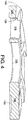
- FIG. 1 depicts the arrangement of the impeller 14 in a molten metal pump 32.
- a motor 34 is secured to a motor mount 36.
- a riser 38 (indicating this pump to be a transfer-style) through which molten metal is pumped is provided.
- the riser 38 is attached to the motor mount 36 via a riser socket 40.
- a pair of refractory posts 42 are secured by a corresponding pair of post sockets 44, a rear support plate 46 and bolts 48 to the motor mount 36.
- each of the posts 42, and the riser 38 are cemented into a base 50.
- the base 50 includes a pumping chamber 52, in which the impeller 14 is disposed.
- the pumping chamber is constructed such that the impeller bearing ring 10 is adjacent the base bearing ring 54.
- the impeller is rotated within the pumping chamber via a shaft 59 secured to the motor by a threaded connection 60 pinned to a universal joint 62.
- US 2005/0013713 A1 discloses a molten metal impeller comprised of a generally cylindrical graphite body including a plurality of vanes defining passages extending from a top or bottom surface to a side wall, a ceramic cap member secured to the surface of said graphite body, wherein said cap member being comprised of a plurality of vanes at least substantially corresponding to said plurality of graphite body vanes and extending to a rim, wherein said rim having segments between adjacent vanes.
- WO 2007/087515 A refers to a centrifugal pump, which has a pump base with inlet inducer openings that receive molten metal into an impeller chamber.
- An impeller structure in the impeller chamber passes the metal in a radial direction through an outlet inducer opening into a volute passage for discharge into the pool of metal in which the pump is located.
- US 4,128,415 A also discloses an impeller, which is located in a housing. The impeller is mounted on a drive shaft. Furthermore, vanes are mounted on the drive shaft to control the flow motion of a body of molten melting media and metal scrap in the upper portion of the housing by creating a vortex in this body for purposes of mixing the melting media and metal scrap.
- molten metal impeller there is a desire to increase the efficiency of a molten metal impeller. Improving the flow of metal into the impeller is one mechanism by which this is achieved. It is a further desire to limit the degradation of the impeller.
- a graphite material is typically used to construct the impeller. Graphite is prone to degradation when exposed to particles entrained in the molten metal. More specifically, the molten metal may include pieces of the refractory lining of the molten metal furnace, undesirables from the metal feed stock and occlusions which develop via chemical reaction, all of which can cause damage to an impeller.
- a molten metal impeller includes a generally cylindrical graphite body having a plurality of passages extending from a top surface to a side wall.
- a hub is formed in the center of the graphite body.
- a ceramic cap member is secured to the top surface of the graphite body.
- the cap member is comprised of a ring forming a central passage shaped cooperatively to overlap the hub and a plurality of vanes extending radially from the ring to an outer rim.
- the rim has a height between adjacent vanes which increases in the direction of intended impeller rotation.
- the rim also has a height which decreases from its radially outer most edge to an inner most edge.
- a molten metal impeller comprised of a graphite body having a central hub disposed upon a generally disk shaped base and at least two vanes extending from the hub.
- a ceramic cap member engages a top surface of the graphite body.
- the cap member has a central ring sized to overlay the hub and wings extending therefrom.
- the wings are shaped to cooperatively overlay the vanes.
- Each wing includes a terminal end with a vane engaging edge and an opposed chamfered edge.
- a molten metal impeller comprised of a generally cylindrical graphite body.
- the graphite body includes a plurality of vanes defining passages extending from a first surface to a side wall.
- a ceramic cap member is secured to the first surface.
- the cap member is comprised of a plurality of vanes corresponding to the plurality of graphite body vanes and a rim.
- the rim includes a plurality of segments between adjacent vanes wherein the segments have a height profile which increases in the direction of intended impeller rotation.
- At least a portion of said rim can include a chamfered edge.
- Said vanes can include a portion intersecting the rim, wherein said portion being forwadly inclined in the direction of intended impeller rotation.
- a new and improved impeller for use in molten metal pumps is disclosed.
- the impeller is utilized in molten metal pumps to create a forced directional flow of molten zinc or molten aluminum.
- Impeller 100 includes three main components; a graphite body 102, a top cap 104, and a bearing ring 106.
- a hub 108 is centrally formed in the graphite body 102 to receive a shaft.
- the hub and corresponding top cap passage could be formed to have flat surfaces for mating with a cooperatively shaped shaft.
- the present embodiment is functional with an impeller which connects to a shaft via a mechanism other than a hub.
- a threaded post could extend from the impeller body and be received within a threaded bore of a shaft.
- the present disclosure contemplates use with the myriad of shaft impeller connections available to the skilled artisan.
- Graphite body 102 is generally cylindrically shaped and includes a plurality of passages 112 extending from an upper surface 110 to side wall 111. Four or more passages are typically present. Cap 104 is secured (for example via cement) to upper surface110. Although reference is made to passages originating in a top surface, it is noted that bottom feed impellers can similarly benefit from the present disclosure. Accordingly, contemplated within this disclosure are impellers having either top or bottom surface passages or both. Similarly, it is envisioned that the cap can be secured to either or both top and bottom surfaces.
- the cement joinder of the cap member 104 to the graphite body 102 can be enhanced by including cooperative grooves 130 in the mounting surfaces of each (not shown in the graphite body). Moreover, in this manner a cement channel is formed that extends into the top cap 104 and into the graphite body 102. In addition, in certain environments, it may be desirable to extend a pin between the cap member 104 and the graphite body 102.
- Cap member 104 can be shaped to generally match the outline shape of graphite body 102. Cap member 104 further has a top surface 114 profile which encourages induction of fluid.
- vanes 116 extend radially from a central ring 118 to an outer rim 120. Rim 120 include segments between adjacent vanes having a height profile which slopes downwardly from H1 to H2 between adjacent vanes 116. H1 is greater than H2 such that the terminal portion of vanes 116 have a higher leading edge 122 than trailing edge 124 to create a scooping action in the direction of intended rotation 126. In certain embodiments, the ratio of H1:H2 is at least 4:3.
- leading edge 122 may be forwardly canted (in the direction of intended impeller rotation 126) relative to the portion of vane 116 between central ring 118 and outer rim 120.
- Trailing edge 124 can also be forwardly canted.
- top surface 114 includes a flow inducing surface 127 which slants downwardly from its peripheral edge 128 to its inner edge 129 adjacent passages 112, effectively funneling molten metal therein.
- the present design has been found particularly effective in high rock inclusive molten metal environments.
- the high strength cap member has been found to provide increased strength.
- the cap member can be comprised of a fine grain refractory material, such as silicon carbide.
- the material has a suitable coefficient of thermal match to graphite, for example, no more than a three to one difference.
- SiC having a 3,96x10 -6 m/m/°C (2.2x10 -6 in/in/°F) and graphite having a 12.6x10 -7 m/m/°C (7x10 -7 in/in/°F) are sufficiently compatible.
- the grain size of the fine grain refractory is preferably not too fine (for example larger than 3 microns may be desirable; although if a mixture of particle sizes is employed it is feasible even smaller sized particles could be present provided larger sized particles are also present such that for example an average particle size layer greater than 3 micros is achieved) to allow cement to suitably grip the material.
Landscapes
- Engineering & Computer Science (AREA)
- Mechanical Engineering (AREA)
- General Engineering & Computer Science (AREA)
- Structures Of Non-Positive Displacement Pumps (AREA)
- Turbine Rotor Nozzle Sealing (AREA)
- Manufacture And Refinement Of Metals (AREA)
Claims (4)
- Flügelrad (100) für geschmolzenes Metall, das einen im Allgemeinen zylindrischen Graphitkörper (102), der mehrere Flügel aufweist, die Durchlässe (112) definieren, die sich von einer oberen oder unteren Oberfläche (110) zu einer Seitenwand (111) erstrecken, und ein keramisches Kappenelement (104), das an der Oberfläche des Graphitkörpers (102) befestigt ist, umfasst, wobei das Kappenelement (104) mehrere Flügel (116) aufweist, die im Wesentlichen den mehreren Graphitkörperflügeln entsprechen und sich zu einem Rand (120) erstrecken, wobei der Rand (120) Segmente zwischen benachbarten Flügeln (116) aufweist, dadurch gekennzeichnet, dass die Segmente ein Höhenprofil aufweisen, das in Richtung der beabsichtigten Flügelraddrehung (126) zunimmt.
- Flügelrad nach Anspruch 1, wobei mindestens ein Abschnitt des Rands eine Kante mit Kammern umfasst.
- Flügelrad nach Anspruch 1, wobei der Rand entfernt von der Körpermitte des Graphitkörpers eine Oberfläche aufweist, die nach innen geneigt ist.
- Flügelrad nach Anspruch 1, wobei die Flügel (116) einen Abschnitt umfassen, der den Rand (120) schneidet, wobei der Abschnitt in Richtung der beabsichtigten Flügelraddrehung nach vorne geneigt ist.
Priority Applications (1)
| Application Number | Priority Date | Filing Date | Title |
|---|---|---|---|
| PL11801530T PL2591235T3 (pl) | 2010-07-02 | 2011-07-05 | Wirnik roztopionego metalu |
Applications Claiming Priority (2)
| Application Number | Priority Date | Filing Date | Title |
|---|---|---|---|
| US36107510P | 2010-07-02 | 2010-07-02 | |
| PCT/US2011/042944 WO2012003509A2 (en) | 2010-07-02 | 2011-07-05 | Molten metal impeller |
Publications (3)
| Publication Number | Publication Date |
|---|---|
| EP2591235A2 EP2591235A2 (de) | 2013-05-15 |
| EP2591235A4 EP2591235A4 (de) | 2016-11-02 |
| EP2591235B1 true EP2591235B1 (de) | 2019-09-18 |
Family
ID=45399840
Family Applications (1)
| Application Number | Title | Priority Date | Filing Date |
|---|---|---|---|
| EP11801530.4A Active EP2591235B1 (de) | 2010-07-02 | 2011-07-05 | Flüssigmetallimpeller |
Country Status (7)
| Country | Link |
|---|---|
| US (1) | US8899932B2 (de) |
| EP (1) | EP2591235B1 (de) |
| CA (1) | CA2804111C (de) |
| ES (1) | ES2757851T3 (de) |
| MX (2) | MX2013000234A (de) |
| PL (1) | PL2591235T3 (de) |
| WO (1) | WO2012003509A2 (de) |
Families Citing this family (24)
| Publication number | Priority date | Publication date | Assignee | Title |
|---|---|---|---|---|
| US20070253807A1 (en) | 2006-04-28 | 2007-11-01 | Cooper Paul V | Gas-transfer foot |
| US9409232B2 (en) | 2007-06-21 | 2016-08-09 | Molten Metal Equipment Innovations, Llc | Molten metal transfer vessel and method of construction |
| US8366993B2 (en) | 2007-06-21 | 2013-02-05 | Cooper Paul V | System and method for degassing molten metal |
| US9156087B2 (en) | 2007-06-21 | 2015-10-13 | Molten Metal Equipment Innovations, Llc | Molten metal transfer system and rotor |
| US8337746B2 (en) | 2007-06-21 | 2012-12-25 | Cooper Paul V | Transferring molten metal from one structure to another |
| US9205490B2 (en) | 2007-06-21 | 2015-12-08 | Molten Metal Equipment Innovations, Llc | Transfer well system and method for making same |
| US9410744B2 (en) | 2010-05-12 | 2016-08-09 | Molten Metal Equipment Innovations, Llc | Vessel transfer insert and system |
| US9643247B2 (en) | 2007-06-21 | 2017-05-09 | Molten Metal Equipment Innovations, Llc | Molten metal transfer and degassing system |
| US8524146B2 (en) | 2009-08-07 | 2013-09-03 | Paul V. Cooper | Rotary degassers and components therefor |
| US8535603B2 (en) | 2009-08-07 | 2013-09-17 | Paul V. Cooper | Rotary degasser and rotor therefor |
| US10428821B2 (en) | 2009-08-07 | 2019-10-01 | Molten Metal Equipment Innovations, Llc | Quick submergence molten metal pump |
| US8444911B2 (en) | 2009-08-07 | 2013-05-21 | Paul V. Cooper | Shaft and post tensioning device |
| US9108244B2 (en) | 2009-09-09 | 2015-08-18 | Paul V. Cooper | Immersion heater for molten metal |
| CZ2012446A3 (cs) | 2012-07-02 | 2013-08-28 | Jap Trading, S. R. O. | Rotacní zarízení k rafinaci kovové taveniny |
| US9903383B2 (en) | 2013-03-13 | 2018-02-27 | Molten Metal Equipment Innovations, Llc | Molten metal rotor with hardened top |
| US9011761B2 (en) | 2013-03-14 | 2015-04-21 | Paul V. Cooper | Ladle with transfer conduit |
| US10052688B2 (en) | 2013-03-15 | 2018-08-21 | Molten Metal Equipment Innovations, Llc | Transfer pump launder system |
| US10138892B2 (en) | 2014-07-02 | 2018-11-27 | Molten Metal Equipment Innovations, Llc | Rotor and rotor shaft for molten metal |
| US10947980B2 (en) | 2015-02-02 | 2021-03-16 | Molten Metal Equipment Innovations, Llc | Molten metal rotor with hardened blade tips |
| US10267314B2 (en) | 2016-01-13 | 2019-04-23 | Molten Metal Equipment Innovations, Llc | Tensioned support shaft and other molten metal devices |
| US11149747B2 (en) | 2017-11-17 | 2021-10-19 | Molten Metal Equipment Innovations, Llc | Tensioned support post and other molten metal devices |
| US20200360990A1 (en) | 2019-05-17 | 2020-11-19 | Molten Metal Equipment Innovations, Llc | Molten Metal Transfer System and Method |
| US11873845B2 (en) | 2021-05-28 | 2024-01-16 | Molten Metal Equipment Innovations, Llc | Molten metal transfer device |
| US12146508B2 (en) | 2022-05-26 | 2024-11-19 | Molten Metal Equipment Innovations, Llc | Axial pump and riser |
Family Cites Families (17)
| Publication number | Priority date | Publication date | Assignee | Title |
|---|---|---|---|---|
| US4128415A (en) | 1977-12-09 | 1978-12-05 | Aluminum Company Of America | Aluminum scrap reclamation |
| CA2097648C (en) | 1992-06-12 | 1998-04-28 | Ronald E. Gilbert | Molton metal pump with vaned impeller and flow directing pumping chamber |
| US5685701A (en) | 1995-06-01 | 1997-11-11 | Metaullics Systems Co., L.P. | Bearing arrangement for molten aluminum pumps |
| WO1997040276A1 (en) * | 1996-04-23 | 1997-10-30 | Metaullics Systems Co., L.P. | Molten metal impeller |
| US6250881B1 (en) | 1996-05-22 | 2001-06-26 | Metaullics Systems Co., L.P. | Molten metal shaft and impeller bearing assembly |
| AU716224B2 (en) | 1996-08-07 | 2000-02-24 | Metaullics Systems Co., L.P. | Molten metal transfer pump |
| US6019576A (en) * | 1997-09-22 | 2000-02-01 | Thut; Bruno H. | Pumps for pumping molten metal with a stirring action |
| WO2000028219A1 (en) | 1998-11-09 | 2000-05-18 | Metaullics Systems Co., L.P. | Shaft and post assemblies for molten metal pumping apparatus |
| US6074455A (en) | 1999-01-27 | 2000-06-13 | Metaullics Systems Co., L.P. | Aluminum scrap melting process and apparatus |
| US6723276B1 (en) | 2000-08-28 | 2004-04-20 | Paul V. Cooper | Scrap melter and impeller |
| US6709234B2 (en) | 2001-08-31 | 2004-03-23 | Pyrotek, Inc. | Impeller shaft assembly system |
| US7144217B2 (en) | 2001-10-26 | 2006-12-05 | Pyrotek, Inc. | Molten metal pump particle passage system |
| US7402276B2 (en) * | 2003-07-14 | 2008-07-22 | Cooper Paul V | Pump with rotating inlet |
| US6869564B2 (en) | 2002-10-29 | 2005-03-22 | Pyrotek, Inc. | Molten metal pump system |
| US6918741B2 (en) | 2002-11-15 | 2005-07-19 | Pyrotek, Inc. | Molten metal pump impeller system |
| US7326028B2 (en) * | 2005-04-28 | 2008-02-05 | Morando Jorge A | High flow/dual inducer/high efficiency impeller for liquid applications including molten metal |
| AR071921A1 (es) | 2008-05-27 | 2010-07-21 | Weir Minerals Australia Ltd | Rotor de bomba para pasta aguada o pulpa |
-
2011
- 2011-07-05 EP EP11801530.4A patent/EP2591235B1/de active Active
- 2011-07-05 ES ES11801530T patent/ES2757851T3/es active Active
- 2011-07-05 US US13/176,254 patent/US8899932B2/en active Active
- 2011-07-05 CA CA2804111A patent/CA2804111C/en active Active
- 2011-07-05 WO PCT/US2011/042944 patent/WO2012003509A2/en not_active Ceased
- 2011-07-05 MX MX2013000234A patent/MX2013000234A/es active IP Right Grant
- 2011-07-05 MX MX2015010710A patent/MX342817B/es unknown
- 2011-07-05 PL PL11801530T patent/PL2591235T3/pl unknown
Non-Patent Citations (1)
| Title |
|---|
| None * |
Also Published As
| Publication number | Publication date |
|---|---|
| EP2591235A4 (de) | 2016-11-02 |
| PL2591235T3 (pl) | 2020-04-30 |
| US8899932B2 (en) | 2014-12-02 |
| WO2012003509A2 (en) | 2012-01-05 |
| CA2804111C (en) | 2018-07-24 |
| MX2013000234A (es) | 2013-03-06 |
| US20120003099A1 (en) | 2012-01-05 |
| WO2012003509A3 (en) | 2013-07-11 |
| MX342817B (es) | 2016-10-13 |
| CA2804111A1 (en) | 2012-01-05 |
| ES2757851T3 (es) | 2020-04-30 |
| EP2591235A2 (de) | 2013-05-15 |
Similar Documents
| Publication | Publication Date | Title |
|---|---|---|
| EP2591235B1 (de) | Flüssigmetallimpeller | |
| US9458724B2 (en) | Molten metal impeller | |
| EP1070204B1 (de) | Pumpenrad zum pumpen von geschmolzenen metall | |
| JP3494452B2 (ja) | 翼付インペラを有する溶融金属用ポンプ | |
| US5785494A (en) | Molten metal impeller | |
| US6524066B2 (en) | Impeller for molten metal pump with reduced clogging | |
| US5634770A (en) | Molten metal pump with vaned impeller | |
| US8110141B2 (en) | Pump with rotating inlet | |
| WO2007087515A2 (en) | High flow/dual inducer/high efficiency impeller for liquid applications including molten metal | |
| US6918741B2 (en) | Molten metal pump impeller system | |
| US20250215887A1 (en) | Molten metal impeller with rock guard |
Legal Events
| Date | Code | Title | Description |
|---|---|---|---|
| PUAI | Public reference made under article 153(3) epc to a published international application that has entered the european phase |
Free format text: ORIGINAL CODE: 0009012 |
|
| 17P | Request for examination filed |
Effective date: 20130116 |
|
| AK | Designated contracting states |
Kind code of ref document: A2 Designated state(s): AL AT BE BG CH CY CZ DE DK EE ES FI FR GB GR HR HU IE IS IT LI LT LU LV MC MK MT NL NO PL PT RO RS SE SI SK SM TR |
|
| R17D | Deferred search report published (corrected) |
Effective date: 20130711 |
|
| RIC1 | Information provided on ipc code assigned before grant |
Ipc: F04D 29/24 20060101AFI20130712BHEP Ipc: F04D 29/18 20060101ALI20130712BHEP |
|
| DAX | Request for extension of the european patent (deleted) | ||
| A4 | Supplementary search report drawn up and despatched |
Effective date: 20161004 |
|
| RIC1 | Information provided on ipc code assigned before grant |
Ipc: F04D 29/18 20060101ALI20160927BHEP Ipc: F04D 29/24 20060101AFI20160927BHEP |
|
| REG | Reference to a national code |
Ref country code: DE Ref legal event code: R079 Ref document number: 602011062193 Country of ref document: DE Free format text: PREVIOUS MAIN CLASS: F04D0007000000 Ipc: F04D0029220000 |
|
| GRAP | Despatch of communication of intention to grant a patent |
Free format text: ORIGINAL CODE: EPIDOSNIGR1 |
|
| STAA | Information on the status of an ep patent application or granted ep patent |
Free format text: STATUS: GRANT OF PATENT IS INTENDED |
|
| RIC1 | Information provided on ipc code assigned before grant |
Ipc: F04D 7/06 20060101ALI20190313BHEP Ipc: F04D 29/22 20060101AFI20190313BHEP |
|
| INTG | Intention to grant announced |
Effective date: 20190405 |
|
| GRAS | Grant fee paid |
Free format text: ORIGINAL CODE: EPIDOSNIGR3 |
|
| GRAA | (expected) grant |
Free format text: ORIGINAL CODE: 0009210 |
|
| STAA | Information on the status of an ep patent application or granted ep patent |
Free format text: STATUS: THE PATENT HAS BEEN GRANTED |
|
| AK | Designated contracting states |
Kind code of ref document: B1 Designated state(s): AL AT BE BG CH CY CZ DE DK EE ES FI FR GB GR HR HU IE IS IT LI LT LU LV MC MK MT NL NO PL PT RO RS SE SI SK SM TR |
|
| REG | Reference to a national code |
Ref country code: GB Ref legal event code: FG4D |
|
| REG | Reference to a national code |
Ref country code: CH Ref legal event code: EP |
|
| REG | Reference to a national code |
Ref country code: DE Ref legal event code: R096 Ref document number: 602011062193 Country of ref document: DE |
|
| REG | Reference to a national code |
Ref country code: AT Ref legal event code: REF Ref document number: 1181640 Country of ref document: AT Kind code of ref document: T Effective date: 20191015 |
|
| REG | Reference to a national code |
Ref country code: IE Ref legal event code: FG4D |
|
| REG | Reference to a national code |
Ref country code: NL Ref legal event code: MP Effective date: 20190918 |
|
| PG25 | Lapsed in a contracting state [announced via postgrant information from national office to epo] |
Ref country code: BG Free format text: LAPSE BECAUSE OF FAILURE TO SUBMIT A TRANSLATION OF THE DESCRIPTION OR TO PAY THE FEE WITHIN THE PRESCRIBED TIME-LIMIT Effective date: 20191218 Ref country code: SE Free format text: LAPSE BECAUSE OF FAILURE TO SUBMIT A TRANSLATION OF THE DESCRIPTION OR TO PAY THE FEE WITHIN THE PRESCRIBED TIME-LIMIT Effective date: 20190918 Ref country code: HR Free format text: LAPSE BECAUSE OF FAILURE TO SUBMIT A TRANSLATION OF THE DESCRIPTION OR TO PAY THE FEE WITHIN THE PRESCRIBED TIME-LIMIT Effective date: 20190918 Ref country code: NO Free format text: LAPSE BECAUSE OF FAILURE TO SUBMIT A TRANSLATION OF THE DESCRIPTION OR TO PAY THE FEE WITHIN THE PRESCRIBED TIME-LIMIT Effective date: 20191218 Ref country code: LT Free format text: LAPSE BECAUSE OF FAILURE TO SUBMIT A TRANSLATION OF THE DESCRIPTION OR TO PAY THE FEE WITHIN THE PRESCRIBED TIME-LIMIT Effective date: 20190918 Ref country code: FI Free format text: LAPSE BECAUSE OF FAILURE TO SUBMIT A TRANSLATION OF THE DESCRIPTION OR TO PAY THE FEE WITHIN THE PRESCRIBED TIME-LIMIT Effective date: 20190918 |
|
| REG | Reference to a national code |
Ref country code: LT Ref legal event code: MG4D |
|
| PG25 | Lapsed in a contracting state [announced via postgrant information from national office to epo] |
Ref country code: LV Free format text: LAPSE BECAUSE OF FAILURE TO SUBMIT A TRANSLATION OF THE DESCRIPTION OR TO PAY THE FEE WITHIN THE PRESCRIBED TIME-LIMIT Effective date: 20190918 Ref country code: AL Free format text: LAPSE BECAUSE OF FAILURE TO SUBMIT A TRANSLATION OF THE DESCRIPTION OR TO PAY THE FEE WITHIN THE PRESCRIBED TIME-LIMIT Effective date: 20190918 Ref country code: RS Free format text: LAPSE BECAUSE OF FAILURE TO SUBMIT A TRANSLATION OF THE DESCRIPTION OR TO PAY THE FEE WITHIN THE PRESCRIBED TIME-LIMIT Effective date: 20190918 |
|
| REG | Reference to a national code |
Ref country code: AT Ref legal event code: MK05 Ref document number: 1181640 Country of ref document: AT Kind code of ref document: T Effective date: 20190918 |
|
| REG | Reference to a national code |
Ref country code: GR Ref legal event code: EP Ref document number: 20190403857 Country of ref document: GR Effective date: 20200318 |
|
| REG | Reference to a national code |
Ref country code: ES Ref legal event code: FG2A Ref document number: 2757851 Country of ref document: ES Kind code of ref document: T3 Effective date: 20200430 |
|
| PG25 | Lapsed in a contracting state [announced via postgrant information from national office to epo] |
Ref country code: PT Free format text: LAPSE BECAUSE OF FAILURE TO SUBMIT A TRANSLATION OF THE DESCRIPTION OR TO PAY THE FEE WITHIN THE PRESCRIBED TIME-LIMIT Effective date: 20200120 Ref country code: AT Free format text: LAPSE BECAUSE OF FAILURE TO SUBMIT A TRANSLATION OF THE DESCRIPTION OR TO PAY THE FEE WITHIN THE PRESCRIBED TIME-LIMIT Effective date: 20190918 Ref country code: EE Free format text: LAPSE BECAUSE OF FAILURE TO SUBMIT A TRANSLATION OF THE DESCRIPTION OR TO PAY THE FEE WITHIN THE PRESCRIBED TIME-LIMIT Effective date: 20190918 Ref country code: RO Free format text: LAPSE BECAUSE OF FAILURE TO SUBMIT A TRANSLATION OF THE DESCRIPTION OR TO PAY THE FEE WITHIN THE PRESCRIBED TIME-LIMIT Effective date: 20190918 Ref country code: NL Free format text: LAPSE BECAUSE OF FAILURE TO SUBMIT A TRANSLATION OF THE DESCRIPTION OR TO PAY THE FEE WITHIN THE PRESCRIBED TIME-LIMIT Effective date: 20190918 |
|
| PG25 | Lapsed in a contracting state [announced via postgrant information from national office to epo] |
Ref country code: IS Free format text: LAPSE BECAUSE OF FAILURE TO SUBMIT A TRANSLATION OF THE DESCRIPTION OR TO PAY THE FEE WITHIN THE PRESCRIBED TIME-LIMIT Effective date: 20200224 Ref country code: SK Free format text: LAPSE BECAUSE OF FAILURE TO SUBMIT A TRANSLATION OF THE DESCRIPTION OR TO PAY THE FEE WITHIN THE PRESCRIBED TIME-LIMIT Effective date: 20190918 Ref country code: CZ Free format text: LAPSE BECAUSE OF FAILURE TO SUBMIT A TRANSLATION OF THE DESCRIPTION OR TO PAY THE FEE WITHIN THE PRESCRIBED TIME-LIMIT Effective date: 20190918 Ref country code: SM Free format text: LAPSE BECAUSE OF FAILURE TO SUBMIT A TRANSLATION OF THE DESCRIPTION OR TO PAY THE FEE WITHIN THE PRESCRIBED TIME-LIMIT Effective date: 20190918 |
|
| REG | Reference to a national code |
Ref country code: DE Ref legal event code: R097 Ref document number: 602011062193 Country of ref document: DE |
|
| PLBE | No opposition filed within time limit |
Free format text: ORIGINAL CODE: 0009261 |
|
| STAA | Information on the status of an ep patent application or granted ep patent |
Free format text: STATUS: NO OPPOSITION FILED WITHIN TIME LIMIT |
|
| PG2D | Information on lapse in contracting state deleted |
Ref country code: IS |
|
| PG25 | Lapsed in a contracting state [announced via postgrant information from national office to epo] |
Ref country code: DK Free format text: LAPSE BECAUSE OF FAILURE TO SUBMIT A TRANSLATION OF THE DESCRIPTION OR TO PAY THE FEE WITHIN THE PRESCRIBED TIME-LIMIT Effective date: 20190918 Ref country code: IS Free format text: LAPSE BECAUSE OF FAILURE TO SUBMIT A TRANSLATION OF THE DESCRIPTION OR TO PAY THE FEE WITHIN THE PRESCRIBED TIME-LIMIT Effective date: 20200119 |
|
| 26N | No opposition filed |
Effective date: 20200619 |
|
| PG25 | Lapsed in a contracting state [announced via postgrant information from national office to epo] |
Ref country code: SI Free format text: LAPSE BECAUSE OF FAILURE TO SUBMIT A TRANSLATION OF THE DESCRIPTION OR TO PAY THE FEE WITHIN THE PRESCRIBED TIME-LIMIT Effective date: 20190918 |
|
| PG25 | Lapsed in a contracting state [announced via postgrant information from national office to epo] |
Ref country code: MC Free format text: LAPSE BECAUSE OF FAILURE TO SUBMIT A TRANSLATION OF THE DESCRIPTION OR TO PAY THE FEE WITHIN THE PRESCRIBED TIME-LIMIT Effective date: 20190918 |
|
| REG | Reference to a national code |
Ref country code: CH Ref legal event code: PL |
|
| REG | Reference to a national code |
Ref country code: BE Ref legal event code: MM Effective date: 20200731 |
|
| PG25 | Lapsed in a contracting state [announced via postgrant information from national office to epo] |
Ref country code: FR Free format text: LAPSE BECAUSE OF NON-PAYMENT OF DUE FEES Effective date: 20200731 Ref country code: LU Free format text: LAPSE BECAUSE OF NON-PAYMENT OF DUE FEES Effective date: 20200705 Ref country code: IE Free format text: LAPSE BECAUSE OF NON-PAYMENT OF DUE FEES Effective date: 20200705 Ref country code: LI Free format text: LAPSE BECAUSE OF NON-PAYMENT OF DUE FEES Effective date: 20200731 Ref country code: CH Free format text: LAPSE BECAUSE OF NON-PAYMENT OF DUE FEES Effective date: 20200731 |
|
| PG25 | Lapsed in a contracting state [announced via postgrant information from national office to epo] |
Ref country code: BE Free format text: LAPSE BECAUSE OF NON-PAYMENT OF DUE FEES Effective date: 20200731 |
|
| PG25 | Lapsed in a contracting state [announced via postgrant information from national office to epo] |
Ref country code: TR Free format text: LAPSE BECAUSE OF FAILURE TO SUBMIT A TRANSLATION OF THE DESCRIPTION OR TO PAY THE FEE WITHIN THE PRESCRIBED TIME-LIMIT Effective date: 20190918 Ref country code: MT Free format text: LAPSE BECAUSE OF FAILURE TO SUBMIT A TRANSLATION OF THE DESCRIPTION OR TO PAY THE FEE WITHIN THE PRESCRIBED TIME-LIMIT Effective date: 20190918 Ref country code: CY Free format text: LAPSE BECAUSE OF FAILURE TO SUBMIT A TRANSLATION OF THE DESCRIPTION OR TO PAY THE FEE WITHIN THE PRESCRIBED TIME-LIMIT Effective date: 20190918 |
|
| PG25 | Lapsed in a contracting state [announced via postgrant information from national office to epo] |
Ref country code: MK Free format text: LAPSE BECAUSE OF FAILURE TO SUBMIT A TRANSLATION OF THE DESCRIPTION OR TO PAY THE FEE WITHIN THE PRESCRIBED TIME-LIMIT Effective date: 20190918 |
|
| PGFP | Annual fee paid to national office [announced via postgrant information from national office to epo] |
Ref country code: PL Payment date: 20250616 Year of fee payment: 15 |
|
| PGFP | Annual fee paid to national office [announced via postgrant information from national office to epo] |
Ref country code: GB Payment date: 20250612 Year of fee payment: 15 |
|
| PGFP | Annual fee paid to national office [announced via postgrant information from national office to epo] |
Ref country code: GR Payment date: 20250625 Year of fee payment: 15 |
|
| PGFP | Annual fee paid to national office [announced via postgrant information from national office to epo] |
Ref country code: ES Payment date: 20250814 Year of fee payment: 15 |
|
| PGFP | Annual fee paid to national office [announced via postgrant information from national office to epo] |
Ref country code: DE Payment date: 20250616 Year of fee payment: 15 |
|
| PGFP | Annual fee paid to national office [announced via postgrant information from national office to epo] |
Ref country code: IT Payment date: 20250715 Year of fee payment: 15 |