EP2591229B1 - Joint composite à réduction des encoches - Google Patents
Joint composite à réduction des encoches Download PDFInfo
- Publication number
- EP2591229B1 EP2591229B1 EP11730317.2A EP11730317A EP2591229B1 EP 2591229 B1 EP2591229 B1 EP 2591229B1 EP 11730317 A EP11730317 A EP 11730317A EP 2591229 B1 EP2591229 B1 EP 2591229B1
- Authority
- EP
- European Patent Office
- Prior art keywords
- fibre
- flange
- core
- blade according
- face
- Prior art date
- Legal status (The legal status is an assumption and is not a legal conclusion. Google has not performed a legal analysis and makes no representation as to the accuracy of the status listed.)
- Active
Links
- 239000002131 composite material Substances 0.000 title description 2
- 230000007704 transition Effects 0.000 claims description 44
- 239000000835 fiber Substances 0.000 claims description 29
- 229920005989 resin Polymers 0.000 claims description 25
- 239000011347 resin Substances 0.000 claims description 25
- 239000000945 filler Substances 0.000 claims description 16
- 229920002430 Fibre-reinforced plastic Polymers 0.000 claims description 15
- 239000011151 fibre-reinforced plastic Substances 0.000 claims description 14
- 239000000463 material Substances 0.000 claims description 11
- 229920000642 polymer Polymers 0.000 claims description 5
- 239000003365 glass fiber Substances 0.000 claims description 4
- 240000007182 Ochroma pyramidale Species 0.000 claims description 2
- 239000011162 core material Substances 0.000 description 60
- 230000003014 reinforcing effect Effects 0.000 description 11
- 208000010392 Bone Fractures Diseases 0.000 description 9
- 206010017076 Fracture Diseases 0.000 description 9
- 239000003292 glue Substances 0.000 description 6
- 230000000694 effects Effects 0.000 description 5
- 230000001419 dependent effect Effects 0.000 description 4
- 238000004026 adhesive bonding Methods 0.000 description 3
- 239000011152 fibreglass Substances 0.000 description 3
- 238000004519 manufacturing process Methods 0.000 description 3
- OKTJSMMVPCPJKN-UHFFFAOYSA-N Carbon Chemical compound [C] OKTJSMMVPCPJKN-UHFFFAOYSA-N 0.000 description 2
- 229910000831 Steel Inorganic materials 0.000 description 2
- 239000000853 adhesive Substances 0.000 description 2
- 230000001070 adhesive effect Effects 0.000 description 2
- 239000007767 bonding agent Substances 0.000 description 2
- 229910052799 carbon Inorganic materials 0.000 description 2
- 238000010276 construction Methods 0.000 description 2
- 239000002245 particle Substances 0.000 description 2
- 239000010959 steel Substances 0.000 description 2
- 235000017166 Bambusa arundinacea Nutrition 0.000 description 1
- 235000017491 Bambusa tulda Nutrition 0.000 description 1
- 241001330002 Bambuseae Species 0.000 description 1
- 241000196324 Embryophyta Species 0.000 description 1
- 239000004593 Epoxy Substances 0.000 description 1
- 235000015334 Phyllostachys viridis Nutrition 0.000 description 1
- 239000004760 aramid Substances 0.000 description 1
- 229920003235 aromatic polyamide Polymers 0.000 description 1
- 239000011425 bamboo Substances 0.000 description 1
- 230000007423 decrease Effects 0.000 description 1
- 239000006261 foam material Substances 0.000 description 1
- 239000011521 glass Substances 0.000 description 1
- 239000010922 glass waste Substances 0.000 description 1
- 229920000728 polyester Polymers 0.000 description 1
- 239000000843 powder Substances 0.000 description 1
- 230000002787 reinforcement Effects 0.000 description 1
- 229920001567 vinyl ester resin Polymers 0.000 description 1
- XLYOFNOQVPJJNP-UHFFFAOYSA-N water Substances O XLYOFNOQVPJJNP-UHFFFAOYSA-N 0.000 description 1
- 239000002023 wood Substances 0.000 description 1
Images


Classifications
-
- F—MECHANICAL ENGINEERING; LIGHTING; HEATING; WEAPONS; BLASTING
- F03—MACHINES OR ENGINES FOR LIQUIDS; WIND, SPRING, OR WEIGHT MOTORS; PRODUCING MECHANICAL POWER OR A REACTIVE PROPULSIVE THRUST, NOT OTHERWISE PROVIDED FOR
- F03D—WIND MOTORS
- F03D1/00—Wind motors with rotation axis substantially parallel to the air flow entering the rotor
- F03D1/06—Rotors
- F03D1/065—Rotors characterised by their construction elements
- F03D1/0675—Rotors characterised by their construction elements of the blades
-
- F—MECHANICAL ENGINEERING; LIGHTING; HEATING; WEAPONS; BLASTING
- F05—INDEXING SCHEMES RELATING TO ENGINES OR PUMPS IN VARIOUS SUBCLASSES OF CLASSES F01-F04
- F05B—INDEXING SCHEME RELATING TO WIND, SPRING, WEIGHT, INERTIA OR LIKE MOTORS, TO MACHINES OR ENGINES FOR LIQUIDS COVERED BY SUBCLASSES F03B, F03D AND F03G
- F05B2280/00—Materials; Properties thereof
- F05B2280/60—Properties or characteristics given to material by treatment or manufacturing
- F05B2280/6003—Composites; e.g. fibre-reinforced
-
- F—MECHANICAL ENGINEERING; LIGHTING; HEATING; WEAPONS; BLASTING
- F05—INDEXING SCHEMES RELATING TO ENGINES OR PUMPS IN VARIOUS SUBCLASSES OF CLASSES F01-F04
- F05C—INDEXING SCHEME RELATING TO MATERIALS, MATERIAL PROPERTIES OR MATERIAL CHARACTERISTICS FOR MACHINES, ENGINES OR PUMPS OTHER THAN NON-POSITIVE-DISPLACEMENT MACHINES OR ENGINES
- F05C2253/00—Other material characteristics; Treatment of material
- F05C2253/04—Composite, e.g. fibre-reinforced
-
- Y—GENERAL TAGGING OF NEW TECHNOLOGICAL DEVELOPMENTS; GENERAL TAGGING OF CROSS-SECTIONAL TECHNOLOGIES SPANNING OVER SEVERAL SECTIONS OF THE IPC; TECHNICAL SUBJECTS COVERED BY FORMER USPC CROSS-REFERENCE ART COLLECTIONS [XRACs] AND DIGESTS
- Y02—TECHNOLOGIES OR APPLICATIONS FOR MITIGATION OR ADAPTATION AGAINST CLIMATE CHANGE
- Y02E—REDUCTION OF GREENHOUSE GAS [GHG] EMISSIONS, RELATED TO ENERGY GENERATION, TRANSMISSION OR DISTRIBUTION
- Y02E10/00—Energy generation through renewable energy sources
- Y02E10/70—Wind energy
- Y02E10/72—Wind turbines with rotation axis in wind direction
Definitions
- the present invention relates to a wind turbine blade for a rotor of a wind turbine and relates also to a wind turbine comprising a wind turbine blade.
- a wind turbine blade for a wind turbine comprises an aerodynamic shell made by two shell parts and at least one beam, normally two or three beams, placed between the shell parts and adhered to the inner side of the shell parts by gluing.
- the beams have a reinforcing function for the turbine blade during operation.
- the shells are often connected to each other in a trailing edge and a leading edge and normally joined by gluing, alternatively, the shell parts may be integrally formed.
- the blade further comprises laminates in the shells for reinforcing these shells.
- the beams absorb large forces during the operation of the blades. Especially the areas close to where the beams are connected to the inside of the shells are subjected to heavy loads which may result in fracture in the beams.
- WO 2008/086805 discloses a wind turbine blade provided with an internal reinforcing floor between the trailing edge and the leading edge to improve resistance against deformation of the shell. This solution increases the complexity of the structure and thus also complexity of manufacture of the blade.
- US 5375324 discloses a wind turbine blade provided with longitudinally extending I-beams connected to an inner face of blade shell halves.
- the I-beams are made of fibre-reinforced polymer and are not provided with a beam core of a core material.
- WO 2010/023140 discloses a wind turbine blade provided with a longitudinally extending box spar having opposite faces being glued to inner faces of blade shell halves, the glue joints having concave frontline surfaces so as to provide a notch-reducing effect in the glue joints.
- JP 61192864 discloses a wind turbine blade formed of three shell parts being mutually connected by means of an adhesive, and a longitudinal beam connected to opposite inner faces of the shell body formed of the three shell parts.
- a first aspect of the present invention is at least partly to overcome the disadvantages of the prior art mentioned above and to provide a wind turbine blade, where the risk of fracture and failure of the beam is reduced.
- the fibre layers of each web continues into the adjacent flange via a concave course in a web-connected flange part having a concavely curved outer surface.
- the concave course of the fibre layers of the web-connecting flange part provides a notch reduction and thereby reduces or eliminates the risk of fracture or failure of the beam.
- an inner chamber accommodating resin is formed between a first inner surface defined by a rounded or chamfered connection between a lateral face and an end face of the beam core defined by fibre layers covering the said connection, a second inner surface defined by the fibre layers of the web-connecting flange part and a third inner surface defined by the fibre layers of the adjacent flange.
- the structure of a chamber together with a sloping or rounded course provides a significant notch-reducing effect.
- the beam will be able to transfer large forces compared to the conventional way of constructing the transition area.
- a curvature radius of the second inner surface is a function of the thickness of the beam core, said curvature radius is increased when the thickness of the beam core between the lateral faces thereof is increased.
- a curvature radius of the first surface i.e. the rounded corner of the core, is a function of the thickness of the beam core between the lateral faces thereof, said curved radius being increased when the thickness of the beam core is increased.
- the entire surface of the beam core including the lateral faces, the end faces and the rounded or chamfered connection between each end face and each lateral face are covered by fibre layers.
- the fibre layers covering the outer surface, especially the rounded or chamfered corner of the core provides a notch-reducing effect.
- the chamber comprises filler embedded in the resin.
- the strength of the transition area is increased as the filler ensures that the risk of dry areas is reduced.
- the filler comprises a longitudinally extending rope for instance comprising glass fibres, and preferably being arranged at the first inner surface.
- the filler is laid out or arranged in an easy manner.
- glass waste in various geometrical shapes such as powder, small rounded or edged particles, could be used.
- the filler is a unidirectional rope.
- Another usable rope is a braided or woven fibre rope.
- the diameter of the fibre rope is 6-15 mm, preferably 9-12 mm.
- the diameter of the fibre rope is dependent on an angle between the first surface and the third surface, the larger angle, the larger the diameter.
- the hollow shell body is a profile contour in the radial direction and divided into a root region with a substantially circular or elliptical profile closest to the hub, an airfoil region with a lift-generating profile furthest away from the hub, and preferably a transition region between the root region and the airfoil region, the transition region having a profile gradually changing in the radial direction from the circular or elliptical profile of the root region to the lift-generating profile of the airfoil region.
- the connection between the inner face of the shell bodies and the flanges of the beam are provided by a bonding agent, such as glue.
- the filler material and/or the fibre material of the beam comprises glass fibres, carbon fibres, steel fibres, aramid or plant fibres.
- the first shell body part forms part of a pressure side
- the second shell part may form part of the suction side
- the chamber is triangular in cross-section.
- the beam core is made of a material having a lower density than the fibre-reinforced polymer, preferably a lower density than the polymer.
- the beam core is made of a foamed material, such as a foamed polymer, or of balsawood.
- the beam is substantially symmetrical about a longitudinal central plane.
- the beam is manufactured by vacuum assisted resin transfer (VARTM).
- VARTM vacuum assisted resin transfer
- the beam is manufactured by using fibre materials pre-impregnated with resin (prepreg.).
- connections between at least one of the end faces and the adjacent lateral faces of the beam core are formed by a section of a circle extending between the lateral faces, especially a half circle as seen in cross section.
- the lateral faces of the beam core are essentially parallel.
- the lateral faces of the beam core converge towards each other from the first towards the second end face.
- the blade has a length of at least 35, 40, 45, 50, 55 or 60 metres.
- the distance between the first outer lateral core surface and the second outer lateral core surface increases towards the first beam flange and towards the second beam flange.
- the radius of curvature of the outer surface of the web-connecting flange part is preferably at least one tenth and more preferred between about one tenth of and four times the width of the core between the lateral faces thereof in the region of the web-connecting flange part.
- the length of the chamfers or the radius of the curvature of the roundings of the beam core is preferably at least one tenth and more preferred between about one tenth of and half the width of the beam core between the lateral surfaces thereof in the region of the chamfer or rounding.
- the radius of curvature is half the width of the core, i.e. the end face of the core is a half circle.
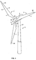
- Fig. 1 illustrates a conventional, modern upwind wind turbine according to the so-called "Danish concept" with a tower 27, a nacelle 28 and a rotor 2 with a substantially horizontal rotor shaft 4.
- the rotor 2 includes a hub 5 and three blades 1 extending radially from the hub 5, each having a blade root 30 nearest the hub, and a blade tip 29 furthest from the hub 5.
- Fig. 3 shows a schematic view of an airfoil profile 38 of a typical blade of a wind turbine depicted with the various parameters, which are typically used to define the geometrical shape of an airfoil.
- the airfoil profile 38 has a pressure side 6 and a suction side 7, which during use, i.e. during rotation of the rotor, normally face towards the windward side and the rearward side, respectively.
- the airfoil 38 has a chord 11 with a chord length 34 extending between a leading edge 9 and a trailing edge 10 of the blade.
- the airfoil 38 has a thickness 35, which is defined as a distance between the pressure side 6 and the suction side 7. The thickness 35 of the airfoil varies along the chord 11.
- the conventional blade 1 comprises a root area 31 closest to the hub, an airfoil area 33 furthest away from the hub, and a transition area 32 between the root area 31 and the airfoil area 33.
- the blade 1 comprises the leading edge 9 facing the direction of rotation of the blade 1 when the blade is mounted on the hub, and the trailing edge 6 facing in the opposite direction to the leading edge 9.
- the airfoil area 33 has an ideal or almost ideal blade shape, whereas the root area 31 has a substantially circular cross-section, which reduces storm loads and makes it easy and safe to mount the blade 1 to the hub.
- the diameter of the root area 31 is constant along the entire root area 31.
- the transition area 32 has a shape, gradually changing from the circular shape of the root area 31 to the airfoil profile of the airfoil area 33. The width of the transition area 32 increases substantially linearly with the increasing distance from the hub.
- the airfoil area 33 has an airfoil profile with a chord plane 11 extending between the leading edge 9 and the trailing edge 10 of the blade 1.
- the width of the chord plane decreases with increasing distance L from the root area 31.
- the chord plane is not necessarily straight over its entire extent since the blade may be twisted and/or curved, thus providing a chord plane with a correspondingly twisted and/or curved course. Often the blades are twisted to compensate for the local velocity of the blade being dependent on the radius from the hub. Due to the circular cross section, the root area 31 does not contribute to the production of the wind turbine and, in fact, lowers the production a little because of the wind resistance.
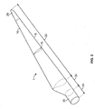
- Fig. 4 shows a perspective view of a blade 1, which has been cut through so as to show the position of two reinforcing beams 15.
- the blade 1 comprises a root section 30 and a blade tip 29, and therebetween the transition area 32 and the airfoil area 33.
- the blade 1 comprises a first shell body part 13 and a second shell body part 14, which are connected to each other at a leading edge 9 and a trailing edge 10.
- the reinforcing beams 15 are arranged between the two shell body parts 13, 14.
- the beams 15 are placed substantially parallel and each comprises a first beam flange 16a connected to the inner surface 18 of the first shell body part 13 and the second beam flange 16b connected to the inner surface 20 of the second shell body part 14.
- the beams are connected to the shell parts by gluing.
- the beams are placed in the transition area 32 and at least a part of the airfoil area 33.
- the blade is manufactured in a conventional way and by a material such as a composite consisting of fibre-reinforced polymer.
- the polymer may be a resin, such as polyester, vinylester or epoxy.
- the fibres may be any suitable type of fibres, such as glass fibres, carbon fibres, steel fibres, bamboo or wood or any combination thereof.
- Fig. 5 is a cross section of a reinforcing beam 15 according to one embodiment of the invention and shows details of one of the beams 15 shown in Fig. 4 .
- the beam 15 comprises a beam core 22, which is advantageously made by a foam material.
- the beam core 22 is defined by a first outer lateral core surface 24a, an opposite second outer lateral core surface 24b, a first outer core end face 52 and a second outer core end face 53 also placed opposite each other and connecting the first and second core surfaces 24a, 24b.
- the cross section of the beam core 22 is essentially rectangular with rounded or chamfered corners.
- the first and second outer core surfaces 24a, 24b are covered by a web 50a, 50b, the web being formed of a fibre-reinforced resin comprising a number of fibre layers.
- the first 52 and second 53 core end faces define inner surfaces 36a, 36b of the respective beam flanges 16a, 16b, the beam flanges being made of a fibre-reinforced resin material comprising a number of fibre layers.
- the beam core 22 and the webs 50 form a beam body 17.
- the first beam flange 16a and the second beam flange 16b comprises an outer surface 37a and 37b, respectively, facing towards the inside of the first and second shell body parts, respectively, and the opposing inner surfaces of the flanges 36a, 36b abut the first 52 and second 53 core end faces of the beam core.
- the outer surfaces 37a and 37b of the flanges 16a, 16b are bonded to the inner surfaces 18, 20 of the shells by a glue 26 or a similar bonding agent.
- the beam flanges 16 might be symmetrically arranged around the longitudinal axes of the beam core 22. By such a construction, it might be easier to place the flanges and the reinforcing beam correct in relation to the shell body parts and ensure that sufficient glue is applied.
- the beam body In the area between the beam body 17 and the respective beam flanges 16a, 16b the beam body is connected to the first beam flange 16a by means of two opposite first transition areas 32a comprising fibre-reinforced polymer.
- the beam body is connected to the second beam flange 16b by means of two opposite second transition areas 32b comprising fibre-reinforced polymer.
- the transition areas 32 transfer the forces between the beam body 17 and the beam flanges 16a, 16b and comprise notch-reducing means by means of which the risk of fracture of the beam is reduced.
- the first transition areas 32a are defined as transition areas closest to the first shell body part 13
- the second transition areas 32b are defined as transition areas closest to the second shell body part 14.
- Each of the first and second transition areas 32a, 32b comprises an outer transition area 39 and an inner transition area 40.
- the outer transition area 39 comprises a flange area located between the outer surface of the flange and the web 50 - named web-connecting flange part 54 - and is connected integrally with the web 50 that covers the core beam 22 by means of fibre-reinforced polymer. In other words, fibre layers of the web extend into the flange.
- the outer surface 51 of the web-connecting flange part 54 is concavely curved with a radius of the curvature that is dependent on the thickness of the web 50.
- the radius of curvature of the outer surface 51 is preferably at least one tenth and more preferred between about one tenth of and about four times the width of the core between the lateral faces thereof in the region of the web-connecting flange part. It is important that the fibre-reinforced resin in this area is made in one piece as this will increase the ability to transfer the forces in the region without any fracture in the transition area.
- the web-connecting flange part 54 of the outer transition area 39 comprises a second surface 43 defined by the fibre layers of the fibre-reinforced polymer.
- Each of the inner transition areas 40 comprises a first surface 42 defined in the embodiment shown in Figs. 5 and 6 by the respective rounded or chamfered corners 49 between each lateral face 24a, 24b and each end face 52, 53 of the beam core. It should, however, be noted that all the faces of the core including the chamfered or rounded corners of the core may be covered by fibre layers. By having a chamfered or rounded surface, the stresses in this region are reduced and the risk of fracture is reduced. In case the corner has a rounded shape, the radius of the curvature is dependent on the thickness of the web 50. The thicker the web, the larger the radius of the curvature.
- the length of the chamfers or the radius of the curvature of the roundings of the beam core is preferably at least one tenth and more preferred between about one tenth of and half the width of the beam core between the lateral surfaces thereof in the region of the chamfer or rounding.
- the radius of curvature is half the width of the core, i.e. the end face of the core is a half circle, as shown by the dotted line for the second end face in Fig. 5 .
- Fig. 6 shows a part of a reinforcing beam 15 comprising the beam core 22.
- the opposing sides of the beam core 22, i.e. the first outer lateral core face 24a and the second outer lateral core face 24b, are covered by a web 50, said web being a fibre-reinforced resin.
- the web 50 continues in the web-connecting flange part 54 towards the flange and is delimited by the curved outer web surface 51 with a radius of the curvature that is a function of the thickness of the web 50.
- the beam core 22 is provided with a chamfer or rounding 49 forming the first surface 42.
- the chamfers or roundings converge towards each other, as shown in Fig. 6 .
- the entire outer surface of the beam core including the chamfered or rounded corners may be covered by fibre layers.
- the fibre layers covering the chamfered or rounded corners define the outer surface 49. It has been shown that a notch-reducing effect is obtained when the core is chamfered or rounded in the above areas.
- first surface 42 Opposite the first surface 42 is a second surface 43 defined by the fibre layers of the web-connecting flange part 54.
- the first 42 and the second 43 surfaces are connected to each other by a third surface 44 defined by the fibre layers of the flange 36.
- the first surface 42 and the second surface 43 meet in an edge 45.
- a chamber 46 is defined by the three surfaces. This chamber has also an impact on the notch-reducing effect in the transition area and increases the resistance against fracture and failure.
- the chamber 46 accommodates the resin 47 and advantageously also a filler 48.
- the filler 48 may be small particles of glass or a fibreglass rope, preferably a unidirectional rope or a non-woven fibreglass rope completely impregnated, i.e. wetted, with resin so as to avoid dry spots.
- the diameter of the fibreglass rope is normally between 6-15 mm, preferably between 9-12 mm, but it depends on the geometry and size of the chamfer 49.
- the filler 48 is placed close to the first surface 42 and placed throughout the length of the beam.
- the beam 15 may advantageously be manufactured by means of VARTM (vacuum-assisted resin transfer).
Landscapes
- Engineering & Computer Science (AREA)
- Life Sciences & Earth Sciences (AREA)
- Sustainable Development (AREA)
- Sustainable Energy (AREA)
- Chemical & Material Sciences (AREA)
- Combustion & Propulsion (AREA)
- Mechanical Engineering (AREA)
- General Engineering & Computer Science (AREA)
- Wind Motors (AREA)
Claims (15)
- Pale d'éolienne pour un rotor d'une éolienne (3) comportant un contour profilé (8) formé par un corps de coque creuse réalisé à partir d'une résine renforcée de fibres, dans laquelle le corps de coque creuse comporte- une première partie de corps de coque (13) et une deuxième partie de corps de coque (14) qui sont raccordées mutuellement et au moins une poutre préfabriquée s'étendant dans le sens longitudinal (15) ayant une coupe transversale en I et étant formée à partir d'une résine renforcée de fibres comportant un certain nombre de couches de fibres, ladite poutre (15) comportant une première semelle de poutre (16a) et une deuxième semelle de poutre (16b) et un corps de poutre (17) s'étendant entre les semelles,ledit corps de poutre (17) comportant un noyau de poutre (22) ayant une première (24a) et une deuxième (24b) faces latérales extérieures espacées mutuellement et une première (52) et une deuxième (53) faces d'extrémité espacées mutuellement, chacune des faces latérales étant recouverte par une âme (50) réalisée en un polymère renforcé de fibres, la première face d'extrémité étant recouverte par du polymère renforcé de fibres de la première semelle de poutre (16a) et la deuxième face d'extrémité étant recouverte par du polymère renforcé de fibres de la deuxième semelle de poutre (16b), le corps de poutre (17) étant formé d'un seul tenant avec la première semelle de poutre (16a) et raccordé à celle-ci par deux premières zones de transition opposées (32a) comportant de la résine renforcée de fibres et formé d'un seul tenant avec la deuxième semelle de poutre (16b) et raccordé à celle-ci par deux deuxièmes zones de transition opposées (32b) comportant de la résine renforcée de fibres,
la première semelle de poutre (16a) étant raccordée à une surface intérieure (18) de la première partie de coque (13) et la deuxième semelle de poutre (16b) étant raccordée à une surface intérieure (19) de la deuxième partie de coque (14),
caractérisée en ce que les zones de transition (32a, 32b) comportent des moyens de réduction d'entailles comportant un raccord arrondi ou chanfreiné entre chacune des faces latérales (24a, 24b) et chacune des faces d'extrémité adjacentes (52, 53) du noyau de poutre (22). - Pale selon la revendication 1, dans laquelle, dans les zones de transition (32a, 32b), les couches de fibres de chaque âme (50) continuent dans la semelle adjacente par le biais d'un tracé concave dans une partie de semelle (54) raccordée à l'âme ayant une surface extérieure courbée de manière concave (51).
- Pale selon la revendication 2, dans laquelle, dans les zones de transition (32a, 32b), une chambre intérieure (46) recevant de la résine est formée entre une première surface intérieure (42) définie par un raccord arrondi ou chanfreiné entre une face latérale et une face d'extrémité du noyau de poutre (22) défini par des couches de fibres recouvrant ledit raccord, une deuxième surface intérieure (43) définie par les couches de fibres de la partie de semelle (54) raccordée à l'âme et une troisième surface intérieure (44) définie par les couches de fibres de la semelle adjacente (16a).
- Pale selon l'une quelconque des revendications précédentes, dans laquelle l'entière surface du noyau de poutre (22) comprenant les faces latérales (24a, 24b), les faces d'extrémité (52, 53) et le raccord arrondi ou chanfreiné entre chaque face d'extrémité et chaque face latérale est recouverte de couches de fibres.
- Pale selon la revendication 3 ou la revendication 4, dans laquelle la chambre (46) comporte une matière de remplissage (48) incorporée dans la résine.
- Pale selon la revendication 5, dans laquelle la matière de remplissage (48) comporte un câble s'étendant dans le sens longitudinal comportant par exemple des fibres de verre, et étant de préférence agencé au niveau de la première surface intérieure.
- Pale selon l'une quelconque des revendications précédentes, dans laquelle le noyau de poutre (22) est réalisé à partir d'un matériau ayant une densité inférieure par rapport au polymère renforcé de fibres, de préférence une densité inférieure par rapport au polymère.
- Pale selon la revendication 7, dans laquelle le noyau de poutre (22) est réalisé à partir d'un matériau alvéolaire, tel qu'un polymère alvéolaire, ou à partir de balsa.
- Pale selon l'une quelconque des revendications précédentes, dans laquelle la poutre (15) est sensiblement symétrique autour d'un plan central longitudinal.
- Pale selon l'une quelconque des revendications précédentes, dans laquelle la poutre (15) est fabriquée par moulage par transfert de résine sous vide (VARTM).
- Pale selon l'une quelconque des revendications précédentes, dans laquelle la poutre (15) est fabriquée en utilisant des matériaux fibreux préimprégnés de résine (préimprégné).
- Pale selon l'une quelconque des revendications précédentes, dans laquelle les raccords entre au moins l'une des faces d'extrémité (52, 53) et des faces latérales adjacentes (24a, 24b) du noyau de poutre (22) sont formés par une section d'un cercle s'étendant entre les faces latérales, en particulier d'un demi-cercle tel que l'on peut voir en coupe transversale.
- Pale selon l'une quelconque des revendications précédentes, dans laquelle les faces latérales (24a, 24b) du noyau de poutre sont sensiblement parallèles.
- Pale selon l'une quelconque des revendications précédentes 1 à 12, dans laquelle les faces latérales (24a, 24b) du noyau de poutre convergent l'une vers l'autre depuis la première vers la deuxième face d'extrémité.
- Pale selon l'une quelconque des revendications précédentes, dans laquelle la pale a une longueur d'au moins 35, 40, 45, 50, 55 ou 60 mètres.
Priority Applications (2)
| Application Number | Priority Date | Filing Date | Title |
|---|---|---|---|
| PL11730317T PL2591229T3 (pl) | 2010-07-08 | 2011-07-08 | Złącze kompozytowe o zmniejszonym karbie |
| EP11730317.2A EP2591229B1 (fr) | 2010-07-08 | 2011-07-08 | Joint composite à réduction des encoches |
Applications Claiming Priority (3)
| Application Number | Priority Date | Filing Date | Title |
|---|---|---|---|
| EP10168803A EP2405130A1 (fr) | 2010-07-08 | 2010-07-08 | Joint composite à rainure réduite |
| PCT/EP2011/061622 WO2012004383A2 (fr) | 2010-07-08 | 2011-07-08 | Joint composite à réduction des encoches |
| EP11730317.2A EP2591229B1 (fr) | 2010-07-08 | 2011-07-08 | Joint composite à réduction des encoches |
Publications (2)
| Publication Number | Publication Date |
|---|---|
| EP2591229A2 EP2591229A2 (fr) | 2013-05-15 |
| EP2591229B1 true EP2591229B1 (fr) | 2016-10-05 |
Family
ID=43086979
Family Applications (2)
| Application Number | Title | Priority Date | Filing Date |
|---|---|---|---|
| EP10168803A Withdrawn EP2405130A1 (fr) | 2010-07-08 | 2010-07-08 | Joint composite à rainure réduite |
| EP11730317.2A Active EP2591229B1 (fr) | 2010-07-08 | 2011-07-08 | Joint composite à réduction des encoches |
Family Applications Before (1)
| Application Number | Title | Priority Date | Filing Date |
|---|---|---|---|
| EP10168803A Withdrawn EP2405130A1 (fr) | 2010-07-08 | 2010-07-08 | Joint composite à rainure réduite |
Country Status (8)
| Country | Link |
|---|---|
| US (1) | US9366223B2 (fr) |
| EP (2) | EP2405130A1 (fr) |
| CN (1) | CN103026058B (fr) |
| BR (1) | BR112012033209B1 (fr) |
| DK (1) | DK2591229T3 (fr) |
| ES (1) | ES2614513T3 (fr) |
| PL (1) | PL2591229T3 (fr) |
| WO (1) | WO2012004383A2 (fr) |
Cited By (1)
| Publication number | Priority date | Publication date | Assignee | Title |
|---|---|---|---|---|
| US11466661B2 (en) | 2020-03-27 | 2022-10-11 | Nordex Energy Se & Co. Kg | Shear web for stiffening a wind turbine rotor blade |
Families Citing this family (10)
| Publication number | Priority date | Publication date | Assignee | Title |
|---|---|---|---|---|
| DK2954199T3 (da) * | 2013-02-07 | 2019-11-11 | Lm Wp Patent Holding As | Slapt, aflangt element med glas stapel fibre |
| CN105899353B (zh) * | 2013-11-19 | 2018-08-14 | Lm Wp 专利控股有限公司 | 用于制造风力涡轮机叶片部件的系统和方法 |
| US20160032889A1 (en) * | 2014-08-02 | 2016-02-04 | Ting Tan | Sustainable hybrid renewable energy system |
| US9951750B2 (en) * | 2015-07-30 | 2018-04-24 | General Electric Company | Rotor blade with interior shelf for a flat plate spar cap |
| CN109598039B (zh) * | 2018-11-21 | 2022-07-08 | 中国电建集团成都勘测设计研究院有限公司 | 对称三岔形梁式岔管及其设计方法 |
| JP7234371B2 (ja) * | 2018-12-11 | 2023-03-07 | ゼネラル・エレクトリック・カンパニイ | 遷移形状を有するセグメント化されたロータブレード用のビーム構造 |
| CN112012877A (zh) * | 2019-05-31 | 2020-12-01 | 江苏金风科技有限公司 | 加强部件、腹板、叶片、成型方法及风力发电机组 |
| CN112012878A (zh) * | 2019-05-31 | 2020-12-01 | 江苏金风科技有限公司 | 腹板、叶片、成型方法以及风力发电机组 |
| CN114673636B (zh) * | 2022-05-30 | 2022-08-23 | 山西天宝集团有限公司 | 一种适合于风电法兰的自动运送设备及其方法 |
| CN115977867B (zh) * | 2023-03-20 | 2023-06-09 | 新创碳谷集团有限公司 | 一种分段式叶片模块结构及其成型方法 |
Family Cites Families (9)
| Publication number | Priority date | Publication date | Assignee | Title |
|---|---|---|---|---|
| JPS61192864A (ja) * | 1985-02-20 | 1986-08-27 | Yamaha Motor Co Ltd | 風車のロ−タブレ−ド構造 |
| US5375324A (en) * | 1993-07-12 | 1994-12-27 | Flowind Corporation | Vertical axis wind turbine with pultruded blades |
| EP1754589B1 (fr) * | 2005-08-17 | 2015-10-14 | General Electric Company | Utilisation de laminés continus, spécialement adaptés comme recouvrement d'un longeron ou comme une autre partie d'une pale d'éolienne |
| EP2104785B1 (fr) | 2007-01-16 | 2014-06-25 | Bladena ApS | Pale renforcée pour éolienne |
| EP2297456A1 (fr) * | 2008-06-23 | 2011-03-23 | Danmarks Tekniske Universitet | Pale d'éolienne avec poutrelle oblique |
| EP2334932B2 (fr) * | 2008-08-25 | 2024-05-01 | Vestas Wind Systems A/S | Assemblage et procédé de préparation d un assemblage |
| US20100098549A1 (en) * | 2008-10-16 | 2010-04-22 | Gabriel Mironov | Wind Turbine Blade |
| US20100124506A1 (en) * | 2008-11-14 | 2010-05-20 | Great Wind Enterprises, Inc. | Vertical axis wind turbine blade |
| CN101555872A (zh) * | 2009-02-20 | 2009-10-14 | 宜兴市华泰国际集团工业有限公司 | 兆瓦级风力发电机叶片 |
-
2010
- 2010-07-08 EP EP10168803A patent/EP2405130A1/fr not_active Withdrawn
-
2011
- 2011-07-08 WO PCT/EP2011/061622 patent/WO2012004383A2/fr active Application Filing
- 2011-07-08 PL PL11730317T patent/PL2591229T3/pl unknown
- 2011-07-08 CN CN201180038829.5A patent/CN103026058B/zh active Active
- 2011-07-08 EP EP11730317.2A patent/EP2591229B1/fr active Active
- 2011-07-08 DK DK11730317.2T patent/DK2591229T3/en active
- 2011-07-08 US US13/808,603 patent/US9366223B2/en active Active
- 2011-07-08 ES ES11730317.2T patent/ES2614513T3/es active Active
- 2011-07-08 BR BR112012033209-0A patent/BR112012033209B1/pt active IP Right Grant
Cited By (1)
| Publication number | Priority date | Publication date | Assignee | Title |
|---|---|---|---|---|
| US11466661B2 (en) | 2020-03-27 | 2022-10-11 | Nordex Energy Se & Co. Kg | Shear web for stiffening a wind turbine rotor blade |
Also Published As
| Publication number | Publication date |
|---|---|
| PL2591229T3 (pl) | 2017-07-31 |
| WO2012004383A3 (fr) | 2012-11-29 |
| EP2405130A1 (fr) | 2012-01-11 |
| BR112012033209B1 (pt) | 2020-12-08 |
| US20130115095A1 (en) | 2013-05-09 |
| US9366223B2 (en) | 2016-06-14 |
| DK2591229T3 (en) | 2017-01-23 |
| WO2012004383A2 (fr) | 2012-01-12 |
| CN103026058B (zh) | 2016-05-04 |
| BR112012033209A2 (pt) | 2016-11-16 |
| CN103026058A (zh) | 2013-04-03 |
| EP2591229A2 (fr) | 2013-05-15 |
| ES2614513T3 (es) | 2017-05-31 |
Similar Documents
| Publication | Publication Date | Title |
|---|---|---|
| EP2591229B1 (fr) | Joint composite à réduction des encoches | |
| EP3488100B1 (fr) | Pale d'éolienne avec segment de dos plat et procédé associé | |
| EP3027893B1 (fr) | Pale de turbine éolienne comportant une ligne de liaison adjacente à un panneau sandwich de la pale | |
| US11028824B2 (en) | Wind turbine blade with a trailing edge spacing section | |
| US10107258B2 (en) | Wind turbine blade for a rotor of a wind turbine | |
| US11994100B2 (en) | Manufacturing of segmented wind turbine blade | |
| US11519383B2 (en) | Wind turbine blade with a plurality of shear webs | |
| US11486350B2 (en) | Wind turbine blade with multiple spar caps | |
| CA3176348A1 (fr) | Pale d'eolienne | |
| US20240018938A1 (en) | Wind turbine blade having buckling-resistant spar caps | |
| US20230175477A1 (en) | Blade shell section and a wind turbine blade comprising a blade shell section | |
| EP4363711A1 (fr) | Pale d'éolienne |
Legal Events
| Date | Code | Title | Description |
|---|---|---|---|
| PUAI | Public reference made under article 153(3) epc to a published international application that has entered the european phase |
Free format text: ORIGINAL CODE: 0009012 |
|
| 17P | Request for examination filed |
Effective date: 20130206 |
|
| AK | Designated contracting states |
Kind code of ref document: A2 Designated state(s): AL AT BE BG CH CY CZ DE DK EE ES FI FR GB GR HR HU IE IS IT LI LT LU LV MC MK MT NL NO PL PT RO RS SE SI SK SM TR |
|
| RAP1 | Party data changed (applicant data changed or rights of an application transferred) |
Owner name: LM WIND POWER A/S |
|
| DAX | Request for extension of the european patent (deleted) | ||
| GRAP | Despatch of communication of intention to grant a patent |
Free format text: ORIGINAL CODE: EPIDOSNIGR1 |
|
| INTG | Intention to grant announced |
Effective date: 20160429 |
|
| GRAS | Grant fee paid |
Free format text: ORIGINAL CODE: EPIDOSNIGR3 |
|
| GRAA | (expected) grant |
Free format text: ORIGINAL CODE: 0009210 |
|
| AK | Designated contracting states |
Kind code of ref document: B1 Designated state(s): AL AT BE BG CH CY CZ DE DK EE ES FI FR GB GR HR HU IE IS IT LI LT LU LV MC MK MT NL NO PL PT RO RS SE SI SK SM TR |
|
| RAP1 | Party data changed (applicant data changed or rights of an application transferred) |
Owner name: LM WP PATENT HOLDING A/S |
|
| REG | Reference to a national code |
Ref country code: GB Ref legal event code: FG4D |
|
| REG | Reference to a national code |
Ref country code: CH Ref legal event code: EP |
|
| REG | Reference to a national code |
Ref country code: AT Ref legal event code: REF Ref document number: 834904 Country of ref document: AT Kind code of ref document: T Effective date: 20161015 |
|
| REG | Reference to a national code |
Ref country code: IE Ref legal event code: FG4D |
|
| REG | Reference to a national code |
Ref country code: DE Ref legal event code: R096 Ref document number: 602011030961 Country of ref document: DE |
|
| REG | Reference to a national code |
Ref country code: DK Ref legal event code: T3 Effective date: 20170119 |
|
| REG | Reference to a national code |
Ref country code: NL Ref legal event code: MP Effective date: 20161005 |
|
| REG | Reference to a national code |
Ref country code: LT Ref legal event code: MG4D |
|
| PG25 | Lapsed in a contracting state [announced via postgrant information from national office to epo] |
Ref country code: LV Free format text: LAPSE BECAUSE OF FAILURE TO SUBMIT A TRANSLATION OF THE DESCRIPTION OR TO PAY THE FEE WITHIN THE PRESCRIBED TIME-LIMIT Effective date: 20161005 |
|
| REG | Reference to a national code |
Ref country code: AT Ref legal event code: MK05 Ref document number: 834904 Country of ref document: AT Kind code of ref document: T Effective date: 20161005 |
|
| PG25 | Lapsed in a contracting state [announced via postgrant information from national office to epo] |
Ref country code: GR Free format text: LAPSE BECAUSE OF FAILURE TO SUBMIT A TRANSLATION OF THE DESCRIPTION OR TO PAY THE FEE WITHIN THE PRESCRIBED TIME-LIMIT Effective date: 20170106 Ref country code: NO Free format text: LAPSE BECAUSE OF FAILURE TO SUBMIT A TRANSLATION OF THE DESCRIPTION OR TO PAY THE FEE WITHIN THE PRESCRIBED TIME-LIMIT Effective date: 20170105 Ref country code: SE Free format text: LAPSE BECAUSE OF FAILURE TO SUBMIT A TRANSLATION OF THE DESCRIPTION OR TO PAY THE FEE WITHIN THE PRESCRIBED TIME-LIMIT Effective date: 20161005 Ref country code: LT Free format text: LAPSE BECAUSE OF FAILURE TO SUBMIT A TRANSLATION OF THE DESCRIPTION OR TO PAY THE FEE WITHIN THE PRESCRIBED TIME-LIMIT Effective date: 20161005 |
|
| PG25 | Lapsed in a contracting state [announced via postgrant information from national office to epo] |
Ref country code: AT Free format text: LAPSE BECAUSE OF FAILURE TO SUBMIT A TRANSLATION OF THE DESCRIPTION OR TO PAY THE FEE WITHIN THE PRESCRIBED TIME-LIMIT Effective date: 20161005 Ref country code: RS Free format text: LAPSE BECAUSE OF FAILURE TO SUBMIT A TRANSLATION OF THE DESCRIPTION OR TO PAY THE FEE WITHIN THE PRESCRIBED TIME-LIMIT Effective date: 20161005 Ref country code: BE Free format text: LAPSE BECAUSE OF FAILURE TO SUBMIT A TRANSLATION OF THE DESCRIPTION OR TO PAY THE FEE WITHIN THE PRESCRIBED TIME-LIMIT Effective date: 20161005 Ref country code: HR Free format text: LAPSE BECAUSE OF FAILURE TO SUBMIT A TRANSLATION OF THE DESCRIPTION OR TO PAY THE FEE WITHIN THE PRESCRIBED TIME-LIMIT Effective date: 20161005 Ref country code: IS Free format text: LAPSE BECAUSE OF FAILURE TO SUBMIT A TRANSLATION OF THE DESCRIPTION OR TO PAY THE FEE WITHIN THE PRESCRIBED TIME-LIMIT Effective date: 20170205 Ref country code: NL Free format text: LAPSE BECAUSE OF FAILURE TO SUBMIT A TRANSLATION OF THE DESCRIPTION OR TO PAY THE FEE WITHIN THE PRESCRIBED TIME-LIMIT Effective date: 20161005 Ref country code: PT Free format text: LAPSE BECAUSE OF FAILURE TO SUBMIT A TRANSLATION OF THE DESCRIPTION OR TO PAY THE FEE WITHIN THE PRESCRIBED TIME-LIMIT Effective date: 20170206 Ref country code: FI Free format text: LAPSE BECAUSE OF FAILURE TO SUBMIT A TRANSLATION OF THE DESCRIPTION OR TO PAY THE FEE WITHIN THE PRESCRIBED TIME-LIMIT Effective date: 20161005 |
|
| REG | Reference to a national code |
Ref country code: ES Ref legal event code: FG2A Ref document number: 2614513 Country of ref document: ES Kind code of ref document: T3 Effective date: 20170531 |
|
| REG | Reference to a national code |
Ref country code: DE Ref legal event code: R097 Ref document number: 602011030961 Country of ref document: DE |
|
| REG | Reference to a national code |
Ref country code: FR Ref legal event code: PLFP Year of fee payment: 7 |
|
| PG25 | Lapsed in a contracting state [announced via postgrant information from national office to epo] |
Ref country code: EE Free format text: LAPSE BECAUSE OF FAILURE TO SUBMIT A TRANSLATION OF THE DESCRIPTION OR TO PAY THE FEE WITHIN THE PRESCRIBED TIME-LIMIT Effective date: 20161005 Ref country code: SK Free format text: LAPSE BECAUSE OF FAILURE TO SUBMIT A TRANSLATION OF THE DESCRIPTION OR TO PAY THE FEE WITHIN THE PRESCRIBED TIME-LIMIT Effective date: 20161005 Ref country code: CZ Free format text: LAPSE BECAUSE OF FAILURE TO SUBMIT A TRANSLATION OF THE DESCRIPTION OR TO PAY THE FEE WITHIN THE PRESCRIBED TIME-LIMIT Effective date: 20161005 Ref country code: RO Free format text: LAPSE BECAUSE OF FAILURE TO SUBMIT A TRANSLATION OF THE DESCRIPTION OR TO PAY THE FEE WITHIN THE PRESCRIBED TIME-LIMIT Effective date: 20161005 |
|
| PLBE | No opposition filed within time limit |
Free format text: ORIGINAL CODE: 0009261 |
|
| STAA | Information on the status of an ep patent application or granted ep patent |
Free format text: STATUS: NO OPPOSITION FILED WITHIN TIME LIMIT |
|
| PG25 | Lapsed in a contracting state [announced via postgrant information from national office to epo] |
Ref country code: BG Free format text: LAPSE BECAUSE OF FAILURE TO SUBMIT A TRANSLATION OF THE DESCRIPTION OR TO PAY THE FEE WITHIN THE PRESCRIBED TIME-LIMIT Effective date: 20170105 Ref country code: SM Free format text: LAPSE BECAUSE OF FAILURE TO SUBMIT A TRANSLATION OF THE DESCRIPTION OR TO PAY THE FEE WITHIN THE PRESCRIBED TIME-LIMIT Effective date: 20161005 Ref country code: IT Free format text: LAPSE BECAUSE OF FAILURE TO SUBMIT A TRANSLATION OF THE DESCRIPTION OR TO PAY THE FEE WITHIN THE PRESCRIBED TIME-LIMIT Effective date: 20161005 |
|
| 26N | No opposition filed |
Effective date: 20170706 |
|
| PG25 | Lapsed in a contracting state [announced via postgrant information from national office to epo] |
Ref country code: SI Free format text: LAPSE BECAUSE OF FAILURE TO SUBMIT A TRANSLATION OF THE DESCRIPTION OR TO PAY THE FEE WITHIN THE PRESCRIBED TIME-LIMIT Effective date: 20161005 |
|
| REG | Reference to a national code |
Ref country code: CH Ref legal event code: PL |
|
| REG | Reference to a national code |
Ref country code: IE Ref legal event code: MM4A |
|
| PG25 | Lapsed in a contracting state [announced via postgrant information from national office to epo] |
Ref country code: CH Free format text: LAPSE BECAUSE OF NON-PAYMENT OF DUE FEES Effective date: 20170731 Ref country code: IE Free format text: LAPSE BECAUSE OF NON-PAYMENT OF DUE FEES Effective date: 20170708 Ref country code: LI Free format text: LAPSE BECAUSE OF NON-PAYMENT OF DUE FEES Effective date: 20170731 |
|
| REG | Reference to a national code |
Ref country code: FR Ref legal event code: PLFP Year of fee payment: 8 |
|
| PG25 | Lapsed in a contracting state [announced via postgrant information from national office to epo] |
Ref country code: LU Free format text: LAPSE BECAUSE OF NON-PAYMENT OF DUE FEES Effective date: 20170708 |
|
| PG25 | Lapsed in a contracting state [announced via postgrant information from national office to epo] |
Ref country code: MT Free format text: LAPSE BECAUSE OF NON-PAYMENT OF DUE FEES Effective date: 20170708 |
|
| PG25 | Lapsed in a contracting state [announced via postgrant information from national office to epo] |
Ref country code: HU Free format text: LAPSE BECAUSE OF FAILURE TO SUBMIT A TRANSLATION OF THE DESCRIPTION OR TO PAY THE FEE WITHIN THE PRESCRIBED TIME-LIMIT; INVALID AB INITIO Effective date: 20110708 Ref country code: MC Free format text: LAPSE BECAUSE OF FAILURE TO SUBMIT A TRANSLATION OF THE DESCRIPTION OR TO PAY THE FEE WITHIN THE PRESCRIBED TIME-LIMIT Effective date: 20161005 |
|
| PG25 | Lapsed in a contracting state [announced via postgrant information from national office to epo] |
Ref country code: CY Free format text: LAPSE BECAUSE OF NON-PAYMENT OF DUE FEES Effective date: 20161005 |
|
| PG25 | Lapsed in a contracting state [announced via postgrant information from national office to epo] |
Ref country code: MK Free format text: LAPSE BECAUSE OF FAILURE TO SUBMIT A TRANSLATION OF THE DESCRIPTION OR TO PAY THE FEE WITHIN THE PRESCRIBED TIME-LIMIT Effective date: 20161005 |
|
| PG25 | Lapsed in a contracting state [announced via postgrant information from national office to epo] |
Ref country code: AL Free format text: LAPSE BECAUSE OF FAILURE TO SUBMIT A TRANSLATION OF THE DESCRIPTION OR TO PAY THE FEE WITHIN THE PRESCRIBED TIME-LIMIT Effective date: 20161005 |
|
| P01 | Opt-out of the competence of the unified patent court (upc) registered |
Effective date: 20230522 |
|
| PGFP | Annual fee paid to national office [announced via postgrant information from national office to epo] |
Ref country code: FR Payment date: 20230621 Year of fee payment: 13 Ref country code: DK Payment date: 20230622 Year of fee payment: 13 |
|
| PGFP | Annual fee paid to national office [announced via postgrant information from national office to epo] |
Ref country code: TR Payment date: 20230626 Year of fee payment: 13 Ref country code: PL Payment date: 20230620 Year of fee payment: 13 |
|
| PGFP | Annual fee paid to national office [announced via postgrant information from national office to epo] |
Ref country code: GB Payment date: 20230620 Year of fee payment: 13 Ref country code: ES Payment date: 20230801 Year of fee payment: 13 |
|
| PGFP | Annual fee paid to national office [announced via postgrant information from national office to epo] |
Ref country code: DE Payment date: 20230620 Year of fee payment: 13 |