EP2591129B1 - Verfahren zur planung des betriebs von energieverteilungsvorrichtungen und anlage zur umsetzung des verfahrens - Google Patents
Verfahren zur planung des betriebs von energieverteilungsvorrichtungen und anlage zur umsetzung des verfahrens Download PDFInfo
- Publication number
- EP2591129B1 EP2591129B1 EP11716304.8A EP11716304A EP2591129B1 EP 2591129 B1 EP2591129 B1 EP 2591129B1 EP 11716304 A EP11716304 A EP 11716304A EP 2591129 B1 EP2591129 B1 EP 2591129B1
- Authority
- EP
- European Patent Office
- Prior art keywords
- time interval
- energy
- time
- distribution device
- duration
- Prior art date
- Legal status (The legal status is an assumption and is not a legal conclusion. Google has not performed a legal analysis and makes no representation as to the accuracy of the status listed.)
- Active
Links
Images


Classifications
-
- G—PHYSICS
- G05—CONTROLLING; REGULATING
- G05B—CONTROL OR REGULATING SYSTEMS IN GENERAL; FUNCTIONAL ELEMENTS OF SUCH SYSTEMS; MONITORING OR TESTING ARRANGEMENTS FOR SUCH SYSTEMS OR ELEMENTS
- G05B13/00—Adaptive control systems, i.e. systems automatically adjusting themselves to have a performance which is optimum according to some preassigned criterion
- G05B13/02—Adaptive control systems, i.e. systems automatically adjusting themselves to have a performance which is optimum according to some preassigned criterion electric
-
- C—CHEMISTRY; METALLURGY
- C21—METALLURGY OF IRON
- C21D—MODIFYING THE PHYSICAL STRUCTURE OF FERROUS METALS; GENERAL DEVICES FOR HEAT TREATMENT OF FERROUS OR NON-FERROUS METALS OR ALLOYS; MAKING METAL MALLEABLE, e.g. BY DECARBURISATION OR TEMPERING
- C21D11/00—Process control or regulation for heat treatments
-
- F—MECHANICAL ENGINEERING; LIGHTING; HEATING; WEAPONS; BLASTING
- F27—FURNACES; KILNS; OVENS; RETORTS
- F27B—FURNACES, KILNS, OVENS OR RETORTS IN GENERAL; OPEN SINTERING OR LIKE APPARATUS
- F27B9/00—Furnaces through which the charge is moved mechanically, e.g. of tunnel type; Similar furnaces in which the charge moves by gravity
- F27B9/30—Details, accessories or equipment specially adapted for furnaces of these types
- F27B9/36—Arrangements of heating devices
-
- F—MECHANICAL ENGINEERING; LIGHTING; HEATING; WEAPONS; BLASTING
- F27—FURNACES; KILNS; OVENS; RETORTS
- F27D—DETAILS OR ACCESSORIES OF FURNACES, KILNS, OVENS OR RETORTS, IN SO FAR AS THEY ARE OF KINDS OCCURRING IN MORE THAN ONE KIND OF FURNACE
- F27D99/00—Subject matter not provided for in other groups of this subclass
- F27D99/0001—Heating elements or systems
- F27D99/0033—Heating elements or systems using burners
Definitions
- the present invention relates to the optimization of the power supply of an installation equipped with energy distribution devices operating in all or nothing and modulation of operating time.
- the energy distribution devices can be in particular burners or electrical resistors.
- the invention relates more particularly to industrial furnaces equipped with burners as energy distribution devices.
- the patent FR 2853959 describes an example of a furnace particularly targeted by the invention.
- each burner is supplied with oxidant and fuel through individual automatic shutoff valves.
- Each valve is equipped with position sensors, for example an opening limit switch and a closing limit switch.
- Two or more power distribution devices can operate in a synchronous manner so that they are always on and off at the same time.
- the synchronous devices are considered as parts of the same power distribution device.
- the oxidant is air and gas fuel, knowing that all types of oxidant and fuel are possible according to the invention.
- the control of the furnace is carried out by means of a control system which, from the needs necessary for the heating of the products, determines the thermal energy demand that each burner must deliver, in particular as a function of its position in the furnace.
- the thermal energy demands are refreshed periodically on the basis of a time interval I , of integer multiple D duration of a time measurement unit ⁇ , typically the second.
- the duration D of the interval of This is a function of the size of the burners, the shut-off valves and the oven. For example set to 60 seconds, it is then adjusted during commissioning, for example between 30 and 120 seconds.
- the demand for thermal energy results in a duration of ignition.
- the opening time ⁇ i and closing of the air and gas valves of each burner is proportional to the thermal energy demand for the burner considered.
- the opening time ⁇ i is less than or at most equal to the duration D of the time interval l .
- the opening and closing of the air and / or gas valves disturb the equilibrium of the pressures in the pipes, in the furnace and in the flue of the products of combustion.
- the disturbances thus created are all the more important as the number of open valves often varies greatly during the time interval.
- the different control loops of the installation are not able to stabilize the pressures if the scheduling of the ignition of the burners is not chosen optimally.
- the term "scheduling" designates the temporal distribution of the operating times of the burners over the time interval I.
- the patent FR2853959 discloses a method of controlling a steelmaking furnace characterized in that the firing order of the burners is selected to reduce pressure variations in the furnace and fuel and fuel supply systems of the furnace. burners. According to this method, the position of the operating sequence of a burner in the time interval T is chosen according to that of the other burners. This solution has limits especially when many burners have an operating sequence of a duration greater than half the duration of the time interval T.
- the first constraint to be faced is that of the time required for a computer or computer that sends the opening and closing instructions to the burner feed valves. It is clear that in an operational framework we only have a few seconds to find a scheduling that meets all the criteria listed above, which excludes the use of the usual approaches of the type exhaustive searches which may require a significant calculation time .
- the order number assigned to each distribution device is a function of the desired operating times
- the device of order number 1 is the one whose desired operating time is the longest
- the order number device N is the one whose desired operating time is the shortest.
- the function U is then the sum of the absolute value of the fluctuations of the energy flow around a mean value during the time interval I and of the variation of the total energy flow between the instant preceding the beginning of the time interval and the instant after the start of the time interval.
- one retains as scheduling that for which the total energy flow generated does not exceed a defined threshold.
- the desired operating times of the power distribution devices are reduced if they lead to a total energy flow that exceeds the defined threshold.
- the difference between the operating time over a time interval I and the desired duration of operation of the device is limited by a maximum difference, in particular 5% of the duration of the interval. of time.
- the sequences for each energy distribution device correspond at most to three changes in the state of the device over a time interval I.
- two successive state changes of each energy distribution device are spaced apart by a minimum time difference which corresponds, for example, to the time required to establish a steady state of the energy distribution device, in particular so to take into account the time of opening or closing of the valves.
- the minimum time difference may be at least one twentieth of the duration D of the time interval, ie D / 20.
- the last change of state during the time interval I is preferably spaced a minimum time difference from the end of the interval, in particular at least one twentieth of the duration. D of the time interval, D / 20.
- the search for the operating sequence or sequences of a power distribution device that make it possible to minimize the function U can be performed in a defined subset of the set of possible sequences.
- the defined subset of the set of possible sequences consists of sequences comprising at most three state changes of a device for distributing energy over a time interval I.
- an initial scheduling is that in which all the energy distribution devices are stopped during the time interval I.
- the sequence number assigned to each distribution device after the first iteration can be randomly chosen.
- the time interval I is advantageously divided into a number M of temporal subdivisions of durations that are not necessarily equal.
- the state changes of the distribution devices take place between two successive temporal subdivisions.
- the states of the distribution devices are coded according to a binary matrix Z of size N x M ( N rows x M columns ), each of which N lines codes the state of the various distribution devices during the successive M temporal subdivisions and each column corresponds to a temporal subdivision.
- the function U is expressed in the form ⁇ i ⁇ j ⁇ ij y i y j , which is the weighted sum of the products of the pairs of components y i y j of a vector Y , with i and j integers between 1 and N x M, and ⁇ ij are weighting coefficients.
- the total energy flow rate resulting from the scheduling is, at each instant of the time interval I , the sum of the flow rates generated by the dispensing devices in operation at this time.
- the objective of the optimization is also to ensure that the energy flow is monotonous, increasing or decreasing, during the time interval.
- the variation of the energy flow rate, between two successive temporal subdivisions, generated by the choice of scheduling of each energy distribution device, must not be greater than a maximum value determined according to the characteristics and reactivities of the different parts of the system.
- these include the characteristics and reactivities of the shut-off valves, the combustion air fan, the pressure regulator on the gas network, the smoke exhaust and the dimensions of the air circuits. gases and fumes.
- the maximum value of the variation is preferably less than or equal to half the value of the energy flow rate before variation.
- the optimization is aimed at ensuring that the total energy flow generated does not exceed a defined threshold.
- This threshold may be different depending on the time interval I considered. It can for example result from the maximum energy flow Q max corresponding to the capacity of the oven. It can also be a function of the energy flow rate of the preceding time interval, for example so as to limit the flow rate variations between two successive time intervals.
- the desired operating times of the power distribution devices are reduced if they lead to a total throughput that exceeds the defined threshold.
- the list of the energy distribution devices is scanned according to a defined order and for each device of the list the scheduling of the ignition of this device is chosen in the subset of the possible values which respects the desired duration of ignition and which minimizes the U function , given the scheduling choices already made for the previous power distribution devices and considering that the following power distribution devices are at a standstill.
- the list of energy distribution devices is scanned in a random order and for each device in the list the scheduling of the ignition of this device in the subset of possible values which respect the desired ignition time and which minimizes the function U, taking into account the orders already made for the other power distribution devices.
- the path of the list of energy distribution devices is repeated a fixed number of times, in particular a hundred, or for a limited time, in particular one to two seconds, and the best scheduling obtained at the end .
- the energy distribution devices are burners and the energy flow rate of the installation is proportional to the feed rate of the fuel burners.
- the power distribution devices may also consist of electrical resistors.
- the method defined above is advantageously used for driving a heating furnace whose energy distribution devices are constituted by burners or electrical resistors.
- the invention also relates to an installation equipped with energy distribution devices operating in all or nothing and modulation of operating time, characterized in that it comprises a computer or computer programmed to control the following power distribution devices a method as defined above, the installation being arranged to execute the scheduling of all the operating sequences of the energy distribution devices, as defined above.
- the installation is advantageously constituted by an industrial oven.
- FIG. 1 schematically shown, an industrial furnace 1, in particular for heating steel products which continuously scroll in the direction of the arrows 2, entering on the left of the furnace 1 and leaving on the right according to the drawn example .
- the oven is equipped with burners B1, B2 ... BN which work in all or nothing (on / off) and in modulation of duration.
- the number N of burners B1, B2... Can be several tens, these burners being distributed, during the design, along the length of the oven, according to the treatments for which this oven is intended.
- Each burner B1, B2 ... is supplied with fuel from a common pipe 3a, 3b, common to several burners, by an automatic valve sectioning 4b1, 4b2 ...
- the pipes 3a, 3b constitute branch branches a pipe 3 generally equipped with a flow meter 3c upstream branches 3a, 3b.
- oxidant especially air or oxygen
- each burner is provided by a general pipe 5 and by branches with valves 6b1, 6b2 ... individual for each burner.
- the valves 4b1, 4b2 ... 6b1, 6b2 ... are controlled by a computer or calculator 7.
- the control of the oven, from the needs necessary for heating the products that will go through this oven, is achieved by means of a program installed in the computer 7.
- the program is adapted to the type of products, at their speed of scrolling, to the desired treatment.
- This program determines, for each burner B1, B2 ... BN the quantity of thermal energy that it must deliver over a time interval I of duration D.
- This quantity of energy corresponds, for a burner Bi, to a duration of operation ⁇ i, less than or equal to the duration D of the time interval I.
- This operating time is specific to each burner and depends in particular on its power, its position and the thermal regime that is desired in the oven.
- the time intervals D have a limited duration, for example from 30 to 120 seconds, and the computer 7 calculates for each successive time interval values ⁇ i for each burner.
- the invention aims to optimize the supply of energy by the set of burners Bi over time intervals I and to limit the pressure fluctuations in the furnace and in the fuel and oxidant supply networks.
- Fig. 2 includes two simplified diagrams.
- Diagram 2.1 represents, for four burners B1, B2, B3, B4 with a possible random ordering, operating times ⁇ 1, ⁇ 2, ⁇ 3, ⁇ 4 assigned to each of the four burners over the time interval I.
- Slots CB1, CB2, CB3, CB4 in Diagram 2.1 illustrate the operating state of the burner.
- the diagram 2.2. represents the energy flow rate Q delivered by the burners, plotted on the ordinate, as a function of the time taken on the abscissa. In this example, the four burners have the same unit power.
- Diagram 2.2 shows a range of recovery times of burners B1, B2, B3, B4 which leads to a peak of the total energy flow to a level Q4.
- Fig. 2 shows a significant variation of the energy flow over the time interval I which is not favorable to good operating conditions and pressure distribution in the furnace 1.
- Fig. 3 illustrates a different scheduling of the operating times of the four burners B1, B2, B3, B4 of Fig. 2 . Only the operation of the burner B1 has been modified with respect to Fig.2 . This was divided into two distinct operating sequences ⁇ 1.1, ⁇ 1.2 corresponding to two slots CB1.1 and CB1.2.
- Diagram 3.2 shows a recovery range of the operating times of the burners B2, B3, B4, but not of the burner B1, which leads to a peak of the total energy flow at a level Q3 less than Q4.
- the scheduling of Fig. 3 for the operating times of the four burners allows, compared to that of Fig.2 , to reduce the variation of energy flow, and therefore the pressure fluctuations in the supply lines, as well as in the furnace, and to improve the operating conditions.
- the operating time ⁇ i may consist of a single operating sequence (of duration ⁇ i), or may be divided as explained with respect to Fig. 7-15 in several sequences of partial durations less than ⁇ i, but whose sum is equal to ⁇ i.
- the U function can take various forms.
- curve 9 represents the energy flow rate Q carried on the ordinate, as a function of the time plotted on the abscissa over the time interval I of duration D, for a determined scheduling of the burners B1 ... BN.
- the area between the curve 9 and the abscissa represents the amount of energy supplied over the time interval I and corresponds to the overall energy supply instruction given in a manner known by the computer 7.
- the curve 9 reflects fluctuations on either side of the average mean value of the flow rate on the interval I represented by the straight line 10, parallel to the abscissa axis. Curve 9 also illustrates the fuel flow fluctuations at the flow meter 3c.
- the straight line 10 determines with the curve 9 equal areas above and below the line 10.
- the curve 9 can be established by the computer 7 which samples n samples, with sufficiently reduced time steps, in particular of the order of one hundredth of D, ie D / 100, and which determines for each of the n samples the energy flow Q j from the burners that will be lit at this time.
- the program installed in the computer 7 provides this minimization treatment which results in an optimal scheduling of the operating times of the burners.
- FIG. 5 Another criterion that can be taken into account for the optimization of the scheduling is schematically illustrated by the diagram of Fig. 5 .
- the curve 11 of flow as a function of time ensures a total amount of energy over the interval I equal to that of Fig.4 and corresponding to the average mean value Q represented by the straight line 12 parallel to the abscissa axis.
- the energy supplied during the interval I corresponds to the area delimited, on the interval I , between the line 12 and the abscissa axis.
- the function U can take into account a determined limit, in particular equal to half the average Q, ie average Q / 2, to maintain the absolute value of the difference between the various values Q j of the representative curve of the speed on the interval I and the average value Q means below this set limit.
- the function U can further take into account the difference in energy flow ( Fig. 5 ) between the end of the previous interval and the beginning of the new interval, corresponding to the vertical segment 14, to minimize this difference in energy flow.
- the optimal scheduling is one that minimizes a function U taking into account not only the fluctuation of the energy flow during the time interval I , but also the variation of the energy flow rate between the instant preceding the start of the time interval and the instant after the start of the time interval.
- the function U may then be the sum of the absolute value of the fluctuations (Q j -Q medium) of the energy flow around a mean average Q value during the time interval I and the change of total flow 14 energy between the instant before the start of the time interval and the moment after the start of the time interval
- Fig. 6 is a diagram showing the taking into account of the slope of the variation of the energy flow (ordinate range) as a function of the time taken on the abscissa in the search for an optimization.
- the optimal scheduling can be determined as being that which makes it possible to obtain an angle of inclination of the flow variation curve, on the mean line 16, which is as small as possible.
- the function U to be minimized can then be defined as the slope of the tangent to the flow curve at a point.
- step c) After having determined a scheduling with an optimal position, or optimal positions in the case of a fractionation, retained for the operating duration of the burner B1 of order number 1, we repeat the step c) from this scheduling by successively considering the burners of higher order number up to the burner of order number N.
- Step e Using as initial scheduling that retained in step d), a new order number from 1 to N is associated with each burner and steps c and d are repeated .
- Step f) Repeating step e) a number of times compatible with the available calculation time before the beginning of the next time interval I ; this number of reiterations depends on the computation speed of the computer 7.
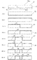
- the time interval I is divided into a number M of temporal subdivisions of durations that are not necessarily equal.
- the changes of state of the burners, or more generally of the energy distribution devices, occur between two successive temporal subdivisions.
- the horizontal dashed lines 18a and 18b represent states of the energy distribution device.
- the energy distribution device is a burner. At level 18a (state "1"), the burner is lit whereas at level 18b ("state 0"), the burner is off.
- FIG. 8 drawings we can see schematically represented the grid of a time interval of Fig. 7 . In this, is shown in thick line 19 the evolution of the state of the burner. In this time interval, the burner is permanently at a standstill.
- FIG. 9 drawings we can see schematically represented the grid of a time interval of Fig. 7 .
- this is represented in thick line 20 the evolution of the state of a burner. During this time, the burner is permanently lit.
- Fig. 10 drawings we can see schematically represented the grid of a time interval of Fig. 7 .
- the burner is ignited on the section 21.
- the burner is switched off and kept at rest on the portion 22.
- Fig. 11 drawings we can see schematically represented the grid of a time interval of Fig.7 .
- the burner is switched off on the section 23.
- the burner is ignited and kept running on the section 24.
- Fig. 12 drawings we can see schematically represented the grid of a time interval of Fig. 7 .
- the burner is switched off on the section 25.
- the burner is ignited and kept running on the section 26.
- the burner is switched off and kept at rest on the portion 27.
- This Fig. 12 represents a time interval comprising a single possible operating sequence according to the invention, with a first change of state between the 3 rd and 4 th temporal subdivision, and a second change of state between the 6 th and 7 th temporal subdivision.
- a sequence similar to that of the Fig. 12 but with a first change of state between the 2 nd and 3 rd time subdivision, and a second change of state between the 7 th and the 8 th temporal subdivision also part of the subset of possible sequences according to the invention .
- Fig.13 drawings we can see schematically represented the grid of a time interval of Fig. 7 .
- the burner In this time interval, the burner is operating on the section 28. Between the 3rd and 4th time subdivision, the burner is switched off and kept at rest on the portion 29. Between the 6th and the 7th time subdivision, the burner is ignited and kept running on the section 30.
- Fig. 14 drawings we can see schematically represented the grid of a time interval of Fig. 7 .
- the burner In this time interval, the burner is operating on the section 31. Between the 3rd and 4th time subdivision, the burner is switched off and kept at rest on the portion 32. Between the 5 th and 6 th temporal subdivision, the burner is ignited and kept running on the section 33. Between the 6th and the 7th time subdivision, the burner is switched off and kept at rest on the portion 34.
- Fig. 15 drawings we can see schematically represented the grid of a time interval of Fig. 7 .
- the burner is stopped on the section 35.
- the burner is ignited and kept running on the section 36.
- the burner is off and kept stationary on the section 37.
- the burner is ignited and maintained in operation on the section 38.
- each change of state may occur at the end of another temporal subdivision.
- the time difference between two changes of state ie the horizontal distance between two successive vertical segments on Fig.12 to 15 is greater than a certain limit, especially one twentieth of the duration D of the interval, greater than D / 20.
- the last change of state on the interval I is separated from the end of this interval I by a minimum time difference, in particular at least one twentieth of the duration D of the interval, namely D / 20.
- the states of the distribution devices are coded according to a binary matrix Z of size N x M, having N rows and M columns, each of the N rows of which codes the state of the different burners during the successive M successive subdivisions, each column corresponding to one temporal subdivision.
- the burners have different powers and are advantageously assigned a weighting coefficient q i representative of the power of the burner considered.
- q i does not depend on the temporal subdivision since the power of the burner is constant.
- Each element of the matrix Z is denoted by y k with k an integer index varying between 1 and NxM, following a row numbering as represented in FIG. Fig.16 .
- the elements y k have the value 0 or 1.
- the function U to be minimized may be the sum of the absolute value of the variations of the energy flow rate between two successive subdivisions during the time interval I.
- the function U to be minimized may be the sum of the square of the variations of the energy flow rate between two successive subdivisions during the time interval I.
- function U can also take one of the forms described above to which additional terms would be added, for example the variation between the first time subdivision of a time interval and the last time subdivision of the interval. previous time.
- the function U can be expressed in the form ⁇ i ⁇ j ⁇ ij y i y j , which is the weighted sum of the products of the pairs of components of a vector Y, with i and j are integer indices between 1 and N x M, and ⁇ ij are weighting coefficients.
- the invention makes it possible to obtain optimum performance of a burner furnace operating in all or nothing, and in modulation of duration.
- the invention ensures a fall in flow fluctuations, better combustion, and a reduction in polluting discharges. During an oven start, the best operating conditions are obtained very quickly and automatically, and are maintained.
- the passage of a method of scheduling the ignition of the burners according to FR2853959 to that according to the invention can reduce by about 30% fluctuations in oxidizer flow rates and fuel.
Landscapes
- Engineering & Computer Science (AREA)
- Mechanical Engineering (AREA)
- Chemical & Material Sciences (AREA)
- General Engineering & Computer Science (AREA)
- Physics & Mathematics (AREA)
- Thermal Sciences (AREA)
- Crystallography & Structural Chemistry (AREA)
- Materials Engineering (AREA)
- Metallurgy (AREA)
- Organic Chemistry (AREA)
- Health & Medical Sciences (AREA)
- Artificial Intelligence (AREA)
- Computer Vision & Pattern Recognition (AREA)
- Evolutionary Computation (AREA)
- Medical Informatics (AREA)
- Software Systems (AREA)
- General Physics & Mathematics (AREA)
- Automation & Control Theory (AREA)
- Regulation And Control Of Combustion (AREA)
- Control Of Combustion (AREA)
- Control Of Heat Treatment Processes (AREA)
Claims (25)
- Verfahren zur Optimierung der Energieversorgung einer Anlage, die mit N im Zweipunkt- und Stetigbetrieb funktionierenden Energieverteilungsvorrichtungen ausgestattet ist, in einem Zeitintervall I mit der Dauer D, wobei jeder der N Energieverteilungsvorrichtungen im Zeitintervall I eine Betriebsdauer Δi kleiner/gleich D zugeordnet wird, wobei die jeweilige Dauer Δi vom Energiebedarf der Anlage abgeleitet und durch ein Steuerungssystem der Anlage angegeben wird, dadurch gekennzeichnet, dass:- die Betriebsdauer Δi einer Energieverteilungsvorrichtung (B1, B2... BN) entweder aus einer einzigen Betriebssequenz mit der Dauer Δi besteht, oder unterteilt ist in mehrere Teilsequenzen mit einer jeweiligen Dauer, deren Summe gleich Δi ist,- durch eine zeitliche Verteilung der Betriebssequenzen der N Energieverteilungsvorrichtungen eine Planung für das Zeitintervall I festgelegt wird,- die Planung vor Beginn des Zeitintervalls I unter Berücksichtigung der für die jeweilige Energieverteilungsvorrichtung gewünschten Betriebsdauer Δi berechnet wird.- und die Planung wie folgt berechnet wird:a/Man wählt einer beliebige Ausgangsplanung.b/Man verknüpft mit jeder Verteilungsvorrichtung eine laufende Nummer von 1 bis N.c/Man sucht für die Verteilungsvorrichtung mit der laufenden Nummer 1 im Zeitintervall I Anzahl, Dauer und Position der Betriebssequenz(en) dieser Verteilungsvorrichtung, die eine Minimierung einer für die Schwankungen des Energiedurchsatzes im Zeitintervall repräsentativen Funktion U ermöglichen, wobei die Sequenzen der anderen Vorrichtungen die Positionen der Ausgangsplanung beibehalten,
und man erhält eine Planung mit optimaler Anzahl, Dauer oder Position für die Sequenzen der Vorrichtung mit der laufenden Nummer 1.d/ Man wiederholt Schritt (c) ausgehend von der Planung, die aus Schritt (10) resultiert, wobei nacheinander die Verteilungsvorrichtungen mit der jeweils höheren laufen Nummer bis zur Verteilungsvorrichtung mit der laufenden Nummer N berücksichtigt werden. - Verfahren nach Anspruch 1, dadurch gekennzeichnet, dass es die folgenden zusätzlichen Schritte umfasst:e/ Unter Benutzung der in Schritt (d) festgehaltenen Planung als Ausgangsplanung verknüpft man mit jeder Verteilungsvorrichtung eine neue laufende Nummer zwischen 1 und N und wiederholt die Schritte (c) und (d).g/ Man wiederholt Schritt (e) so viele Male, wie dies mit der vor Beginn des Zeitintervalls verfügbaren Berechnungszeit vereinbar ist.
- Verfahren nach Anspruch 1, dadurch gekennzeichnet, dass die jeder Verteilungsvorrichtung zugeordnete laufende Nummer abhängig ist von der gewünschten jeweiligen Betriebsdauer Δi, wobei die Vorrichtung mit der laufenden Nummer 1 die Vorrichtung mit der längsten gewünschten Betriebsdauer Δ1, und die Vorrichtung mit der laufenden Nummer N die mit der kürzestem gewünschten Betriebsdauer ΔN ist.
- Verfahren nach einem der vorhergehenden Ansprüche, dadurch gekennzeichnet, dass das Zeitintervall I durch eine Anzahl M zeitlicher Unterteilungen (17) dividiert wird, deren jeweilige Dauer nicht unbedingt gleich lang sein muss.
- Verfahren nach Anspruch 4, dadurch gekennzeichnet, dass die Stati der Verteilungsvorrichtungen nach einer binären Matrix Z mit der Größe N x M (N Zeilen und M Spalten) codiert ist, in der jede der N Zeilen des Status der verschiedenen Verteilungsvorrichtungen in den aufeinanderfolgenden zeitlichen Unterteilungen codiert und jede Spalte einer zeitlichen Unterteilung entspricht.
- Verfahren nach einem der vorhergehenden Ansprüche, dadurch gekennzeichnet, dass die zu minimierende Funktion U die Summe der absoluten Werte der Schwankungen des Energiedurchsatzes Qj um einen Mittelwert Qmoy im Zeitintervall I herum ist:

- Verfahren nach einem der Ansprüche 1 bis 5, dadurch gekennzeichnet, dass die zu minimierende Funktion U gebildet wird aus der Summe der Quadratzahlen der Abweichungen vom arithmetischen Mittel:

- Verfahren nach einem der Ansprüche 1 bis 5, dadurch gekennzeichnet, dass die zu minimierende Funktion U gebildet wird aus der Summe der absoluten Werte der Energiedurchsatzschwankungen zwischen zwei im Zeitintervall I aufeinanderfolgenden Unterteilungen:

- Verfahren nach einem der Ansprüche 1 bis 5, dadurch gekennzeichnet, dass die zu minimierende Funktion U gebildet wird aus der Summe der Quadratzahlen der Energiedurchsatzschwankungen zwischen zwei im Zeitintervall I aufeinanderfolgenden Subdivisionen:

- Verfahren nach einem der Ansprüche 6 bis 9, dadurch gekennzeichnet, dass zu der zu minimierenden Funktion U weitere Terme hinzugefügt werden.
- Verfahren nach Anspruch 1, dadurch gekennzeichnet, dass die zu minimierende Funktion U nicht nur die Schwankung des Energiedurchsatzes im Zeitintervall I berücksichtigt, sondern auch die Schwankung (14) des Energiedurchsatzes zwischen dem Zeitpunkt vor Beginn des Zeitintervalls und dem Zeitpunkt nach Beginn des Zeitintervalls, wobei die Funktion U die Summe der absoluten Werte der Energiedurchsatzschwankungen um einen Mittelwert im Zeitintervall I herum und der Schwankung (14) des Gesamtenergiedurchsatzes zwischen dem Zeitpunkt vor Beginn des Zeitintervalls und dem Zeitpunkt nach Beginn des Zeitintervalls ist.
- Verfahren nach einem der vorhergehenden Ansprüche, dadurch gekennzeichnet, dass man sicherstellt, dass der durch die erzielte Planung entstehende Gesamtenergiedurchsatz einen festgelegten Grenzwert nicht überschreitet.
- Verfahren nach einem der vorhergehenden Ansprüche, dadurch gekennzeichnet, dass die gewünschte Betriebsdauer der jeweiligen Energieverteilungsvorrichtungen verringert wird, wenn diese zu einem Gesamtdurchsatz führt, der einen festgelegten Grenzwert überschreitet.
- Verfahren nach einem der vorhergehenden Ansprüche, dadurch gekennzeichnet, dass die Abweichung bei jeder Energieverteilungsvorrichtung zwischen der Betriebsdauer in einem Zeitintervall I und der gewünschten Dauer begrenzt ist auf eine maximale Abweichung von insbesondere 5 % der Dauer des Zeitintervalls.
- Verfahren nach einem der vorhergehenden Ansprüche, dadurch gekennzeichnet, dass die Sequenzen bei jeder Energieverteilungsvorrichtung höchstens drei Statusänderungen der Vorrichtung in einem Zeitintervall I entsprechen.
- Verfahren nach einem der vorhergehenden Ansprüche, dadurch gekennzeichnet, dass zwischen zwei aufeinanderfolgenden Statusänderungen jeder Energieverteilungsvorrichtung eine Mindestzeitdifferenz besteht, die insbesondere zumindest ein Zwanzigstel der Dauer D des Zeitintervalls, d.h. D/20, ist.
- Verfahren nach einem der vorhergehenden Ansprüche, dadurch gekennzeichnet, dass bei jeder Energieverteilungsvorrichtung zischen der letzten Statusänderung im Zeitintervall I und dem Ende des Intervalls eine Mindestzeitdifferenz besteht, die insbesondere zumindest ein Zwanzigstel der Dauer D des Zeitintervalls, d.h. D/20, ist.
- Verfahren nach einem der vorhergehenden Ansprüche, dadurch gekennzeichnet, dass die Ausgangsplanung die Planung ist, in der alle Energieverteilungsvorrichtungen im Zeitintervall ausgeschaltet sind.
- Verfahren nach einem der vorhergehenden Ansprüche, dadurch gekennzeichnet, dass die jeder Verteilungsvorrichtung nach der ersten Wiederholung zugeordnete laufende Nummer beliebig ist.
- Verfahren nach Anspruch 4, dadurch gekennzeichnet, dass die Statusänderungen der Verteilungsvorrichtungen zwischen zwei aufeinanderfolgenden zeitlichen Unterteilungen stattfinden.
- Verfahren nach einem der vorhergehenden Ansprüche, dadurch gekennzeichnet, dass die Energieverteilungsvorrichtungen Brenner sind, und dadurch, dass sich der Energieversorgungsdurchsatz der Anlage proportional zum Brennstoffversorgungsdurchsatz der Brenner verhält.
- Verfahren nach Anspruch 1, dadurch gekennzeichnet, dass die Funktion U ausgedrückt wird in der Form ∑i ∑j αij γi γj als gewichtete Summe der Produkte der Komponentenpaare eines Vektors γ, wobei i und j ganze Messzahlen zwischen 1 und N x M, und αij Gewichtungskoeffizienten sind.
- Verfahren nach einem der vorhergehenden Ansprüche zum Betreiben eines Wärmofens, dessen Energieverteilungsvorrichtungen aus Brennern oder elektrischen Widerständen bestehen.
- Anlage, die ausgestattet ist mit Energieverteilungsvorrichtungen mit Zweipunkt- und Stetigbetrieb, dadurch gekennzeichnet, dass sie einen Computer oder Rechner umfasst, der so programmiert ist, dass die Energieverteilungsvorrichtungen nach einem Verfahren gemäß den vorhergehenden Ansprüchen gesteuert wird, wobei die Anlage so angeordnet ist, dass die Planung der Betriebssequenzen der Energieverteilungsvorrichtungen gemäß der Definition in den vorhergehenden Ansprüchen ausgeführt wird.
- Anlage nach Anspruch 24 bestehend aus einem Industrieofen.
Priority Applications (1)
| Application Number | Priority Date | Filing Date | Title |
|---|---|---|---|
| PL11716304T PL2591129T3 (pl) | 2010-07-09 | 2011-03-03 | Sposób uporządkowania działania urządzeń do dystrybucji energii oraz instalacja realizująca ten sposób |
Applications Claiming Priority (2)
| Application Number | Priority Date | Filing Date | Title |
|---|---|---|---|
| FR1055596A FR2962528B3 (fr) | 2010-07-09 | 2010-07-09 | Procede d'ordonnancement de fonctionnement de dispositifs de distribution d'energie |
| PCT/IB2011/050899 WO2012004686A1 (fr) | 2010-07-09 | 2011-03-03 | Procédé d'ordonnancement de fonctionnement de dispositifs de distribution d'énergie, et installation mettant en oeuvre ce procédé |
Publications (2)
| Publication Number | Publication Date |
|---|---|
| EP2591129A1 EP2591129A1 (de) | 2013-05-15 |
| EP2591129B1 true EP2591129B1 (de) | 2019-07-17 |
Family
ID=44246424
Family Applications (1)
| Application Number | Title | Priority Date | Filing Date |
|---|---|---|---|
| EP11716304.8A Active EP2591129B1 (de) | 2010-07-09 | 2011-03-03 | Verfahren zur planung des betriebs von energieverteilungsvorrichtungen und anlage zur umsetzung des verfahrens |
Country Status (7)
| Country | Link |
|---|---|
| US (1) | US9639069B2 (de) |
| EP (1) | EP2591129B1 (de) |
| ES (1) | ES2753153T3 (de) |
| FR (1) | FR2962528B3 (de) |
| PL (1) | PL2591129T3 (de) |
| PT (1) | PT2591129T (de) |
| WO (1) | WO2012004686A1 (de) |
Families Citing this family (1)
| Publication number | Priority date | Publication date | Assignee | Title |
|---|---|---|---|---|
| CN112394643B (zh) * | 2020-11-27 | 2021-11-09 | 大连理工大学 | 钢铁企业热电系统调度方法、系统及计算机可读存储介质 |
Family Cites Families (4)
| Publication number | Priority date | Publication date | Assignee | Title |
|---|---|---|---|---|
| BE792478A (fr) * | 1971-12-10 | 1973-03-30 | Ofu | Four industriel chauffe par combustible |
| DE19512633C1 (de) * | 1995-04-05 | 1996-10-17 | Heimsoth Keramische Oefen Und | Verfahren zur Steuerung der Brenner eines Herdwagenofens |
| US6095793A (en) * | 1998-09-18 | 2000-08-01 | Woodward Governor Company | Dynamic control system and method for catalytic combustion process and gas turbine engine utilizing same |
| FR2853959B1 (fr) | 2003-04-18 | 2005-06-24 | Stein Heurtey | Procede de controle de l'homogeneite de temperature des produits dans un four de rechauffage de siderurgie, et four de rechauffage |
-
2010
- 2010-07-09 FR FR1055596A patent/FR2962528B3/fr not_active Expired - Lifetime
-
2011
- 2011-03-03 US US13/808,781 patent/US9639069B2/en active Active
- 2011-03-03 WO PCT/IB2011/050899 patent/WO2012004686A1/fr not_active Ceased
- 2011-03-03 ES ES11716304T patent/ES2753153T3/es active Active
- 2011-03-03 PL PL11716304T patent/PL2591129T3/pl unknown
- 2011-03-03 EP EP11716304.8A patent/EP2591129B1/de active Active
- 2011-03-03 PT PT117163048T patent/PT2591129T/pt unknown
Non-Patent Citations (1)
| Title |
|---|
| None * |
Also Published As
| Publication number | Publication date |
|---|---|
| FR2962528B3 (fr) | 2012-07-27 |
| WO2012004686A1 (fr) | 2012-01-12 |
| FR2962528A3 (fr) | 2012-01-13 |
| US9639069B2 (en) | 2017-05-02 |
| ES2753153T3 (es) | 2020-04-07 |
| PL2591129T3 (pl) | 2020-03-31 |
| US20130116839A1 (en) | 2013-05-09 |
| PT2591129T (pt) | 2019-10-18 |
| EP2591129A1 (de) | 2013-05-15 |
Similar Documents
| Publication | Publication Date | Title |
|---|---|---|
| EP1860664B1 (de) | Verfahren zur Regelung der Leistungsparameter des Kerns eines Druckwasserreaktors | |
| EP1607584A1 (de) | Vorrichtung und Verfahren zur Luftstromsteuerung in einem Triebwerk | |
| EP3009531B1 (de) | Verfahren zum steuern eines elektrolysesystems unter berücksichtigung der temperatur der elektrolyseanlagenmodule besagten elektrolysesystems | |
| WO2012004686A1 (fr) | Procédé d'ordonnancement de fonctionnement de dispositifs de distribution d'énergie, et installation mettant en oeuvre ce procédé | |
| EP2475948B1 (de) | Verfahren zur charakterisierung der verbrennung in den trennwänden eines ofens mit rotierenden brennkammern | |
| EP2951420A1 (de) | Anlage mit einer gasturbine und verfahren zur regelung dieser anlage | |
| EP2010765A1 (de) | Verfahren zur steuerung einer einrichtung zur behandlung von abgasen aus einer brennkraftmaschine | |
| EP0692751A1 (de) | Vorhersagemethoden und unscharfe Logik verwendende Methode und Vorrichtung zur Regelung eines Parameters innerhalb eines zulässigen Bereichs | |
| CA2522816A1 (fr) | Procede de controle de l'homogeneite de temperature des produits dans un four de rechauffage de siderurgie, et four de rechauffage | |
| CH621603A5 (de) | ||
| FR3025326A1 (fr) | Procede de gestion de la consommation d'electricite d'un reseau electrique | |
| FR2992058A3 (fr) | Four de revenu et procede de pilotage | |
| EP2753889B1 (de) | Vorrichtung und verfahren zur optimierung der verbrennung in partitionsreihen eines kammerofens zum brennen von kohlenstoffblöcken | |
| EP3017453B1 (de) | Verfahren zur steuerung eines druckwasserkernreaktors während eines verlängerten reaktorzyklus | |
| FR2978569A1 (fr) | Procede de commande pour gerer le confort d'une zone d'un batiment selon une approche multicriteres et installation pour la mise en oeuvre du procede | |
| FR2924201A1 (fr) | Procede de chauffage au moyen d'un oxybruleur comportant un injecteur dispose a l'interieur d'un bloc | |
| FR3015913A1 (fr) | Procede de pilotage d'une ligne de traitement thermique d'une bande metallique, et ligne pour la mise en oeuvre du procede. | |
| WO2013079576A1 (fr) | Procede de gestion de debit d'eau turbinee d'une pluralite d'usines hydroelectriques | |
| FR3075932A1 (fr) | Procede d'optimisation de la limitation des emissions de poussieres pour les turbines a gaz alimentees au fioul lourd. | |
| EP1585901B1 (de) | Pflanze zur herstellung von druckgas und verfahren zur verwendung dieser pflanze | |
| EP2737589B1 (de) | System zur erzeugung und verteilung elektrischer energie in einem stromnetz und zugehöriges optimierungsverfahren | |
| EP2527737B1 (de) | Verfahren zur regelung der brennstoffzufuhr einer gasturbine und gasturbine | |
| EP3601056B1 (de) | Verfahren zur steuerung eines mehrfachmotorraums, steuerungssystem für einen mehrfachmotorraum und mehrfachmotorraum | |
| EP3258187A1 (de) | Verfahren zur änderung des energieverbrauchs eines geräts | |
| FR3108388A1 (fr) | Procédés pour optimiser le fonctionnement d’une chaudière, dispositifs et chaudières correspondantes |
Legal Events
| Date | Code | Title | Description |
|---|---|---|---|
| PUAI | Public reference made under article 153(3) epc to a published international application that has entered the european phase |
Free format text: ORIGINAL CODE: 0009012 |
|
| 17P | Request for examination filed |
Effective date: 20130107 |
|
| AK | Designated contracting states |
Kind code of ref document: A1 Designated state(s): AL AT BE BG CH CY CZ DE DK EE ES FI FR GB GR HR HU IE IS IT LI LT LU LV MC MK MT NL NO PL PT RO RS SE SI SK SM TR |
|
| DAX | Request for extension of the european patent (deleted) | ||
| STAA | Information on the status of an ep patent application or granted ep patent |
Free format text: STATUS: EXAMINATION IS IN PROGRESS |
|
| 17Q | First examination report despatched |
Effective date: 20170828 |
|
| GRAP | Despatch of communication of intention to grant a patent |
Free format text: ORIGINAL CODE: EPIDOSNIGR1 |
|
| STAA | Information on the status of an ep patent application or granted ep patent |
Free format text: STATUS: GRANT OF PATENT IS INTENDED |
|
| INTG | Intention to grant announced |
Effective date: 20181102 |
|
| GRAJ | Information related to disapproval of communication of intention to grant by the applicant or resumption of examination proceedings by the epo deleted |
Free format text: ORIGINAL CODE: EPIDOSDIGR1 |
|
| STAA | Information on the status of an ep patent application or granted ep patent |
Free format text: STATUS: EXAMINATION IS IN PROGRESS |
|
| GRAP | Despatch of communication of intention to grant a patent |
Free format text: ORIGINAL CODE: EPIDOSNIGR1 |
|
| STAA | Information on the status of an ep patent application or granted ep patent |
Free format text: STATUS: GRANT OF PATENT IS INTENDED |
|
| INTC | Intention to grant announced (deleted) | ||
| INTG | Intention to grant announced |
Effective date: 20190211 |
|
| GRAS | Grant fee paid |
Free format text: ORIGINAL CODE: EPIDOSNIGR3 |
|
| GRAA | (expected) grant |
Free format text: ORIGINAL CODE: 0009210 |
|
| STAA | Information on the status of an ep patent application or granted ep patent |
Free format text: STATUS: THE PATENT HAS BEEN GRANTED |
|
| AK | Designated contracting states |
Kind code of ref document: B1 Designated state(s): AL AT BE BG CH CY CZ DE DK EE ES FI FR GB GR HR HU IE IS IT LI LT LU LV MC MK MT NL NO PL PT RO RS SE SI SK SM TR |
|
| REG | Reference to a national code |
Ref country code: GB Ref legal event code: FG4D Free format text: NOT ENGLISH |
|
| REG | Reference to a national code |
Ref country code: CH Ref legal event code: EP |
|
| REG | Reference to a national code |
Ref country code: IE Ref legal event code: FG4D Free format text: LANGUAGE OF EP DOCUMENT: FRENCH |
|
| REG | Reference to a national code |
Ref country code: DE Ref legal event code: R096 Ref document number: 602011060485 Country of ref document: DE |
|
| REG | Reference to a national code |
Ref country code: AT Ref legal event code: REF Ref document number: 1155894 Country of ref document: AT Kind code of ref document: T Effective date: 20190815 |
|
| REG | Reference to a national code |
Ref country code: PT Ref legal event code: SC4A Ref document number: 2591129 Country of ref document: PT Date of ref document: 20191018 Kind code of ref document: T Free format text: AVAILABILITY OF NATIONAL TRANSLATION Effective date: 20190930 |
|
| REG | Reference to a national code |
Ref country code: SE Ref legal event code: TRGR |
|
| REG | Reference to a national code |
Ref country code: NL Ref legal event code: FP |
|
| REG | Reference to a national code |
Ref country code: LT Ref legal event code: MG4D |
|
| PG25 | Lapsed in a contracting state [announced via postgrant information from national office to epo] |
Ref country code: NO Free format text: LAPSE BECAUSE OF FAILURE TO SUBMIT A TRANSLATION OF THE DESCRIPTION OR TO PAY THE FEE WITHIN THE PRESCRIBED TIME-LIMIT Effective date: 20191017 Ref country code: BG Free format text: LAPSE BECAUSE OF FAILURE TO SUBMIT A TRANSLATION OF THE DESCRIPTION OR TO PAY THE FEE WITHIN THE PRESCRIBED TIME-LIMIT Effective date: 20191017 Ref country code: LT Free format text: LAPSE BECAUSE OF FAILURE TO SUBMIT A TRANSLATION OF THE DESCRIPTION OR TO PAY THE FEE WITHIN THE PRESCRIBED TIME-LIMIT Effective date: 20190717 Ref country code: HR Free format text: LAPSE BECAUSE OF FAILURE TO SUBMIT A TRANSLATION OF THE DESCRIPTION OR TO PAY THE FEE WITHIN THE PRESCRIBED TIME-LIMIT Effective date: 20190717 |
|
| PG25 | Lapsed in a contracting state [announced via postgrant information from national office to epo] |
Ref country code: AL Free format text: LAPSE BECAUSE OF FAILURE TO SUBMIT A TRANSLATION OF THE DESCRIPTION OR TO PAY THE FEE WITHIN THE PRESCRIBED TIME-LIMIT Effective date: 20190717 Ref country code: LV Free format text: LAPSE BECAUSE OF FAILURE TO SUBMIT A TRANSLATION OF THE DESCRIPTION OR TO PAY THE FEE WITHIN THE PRESCRIBED TIME-LIMIT Effective date: 20190717 Ref country code: IS Free format text: LAPSE BECAUSE OF FAILURE TO SUBMIT A TRANSLATION OF THE DESCRIPTION OR TO PAY THE FEE WITHIN THE PRESCRIBED TIME-LIMIT Effective date: 20191117 Ref country code: GR Free format text: LAPSE BECAUSE OF FAILURE TO SUBMIT A TRANSLATION OF THE DESCRIPTION OR TO PAY THE FEE WITHIN THE PRESCRIBED TIME-LIMIT Effective date: 20191018 Ref country code: RS Free format text: LAPSE BECAUSE OF FAILURE TO SUBMIT A TRANSLATION OF THE DESCRIPTION OR TO PAY THE FEE WITHIN THE PRESCRIBED TIME-LIMIT Effective date: 20190717 |
|
| REG | Reference to a national code |
Ref country code: ES Ref legal event code: FG2A Ref document number: 2753153 Country of ref document: ES Kind code of ref document: T3 Effective date: 20200407 |
|
| PG25 | Lapsed in a contracting state [announced via postgrant information from national office to epo] |
Ref country code: RO Free format text: LAPSE BECAUSE OF FAILURE TO SUBMIT A TRANSLATION OF THE DESCRIPTION OR TO PAY THE FEE WITHIN THE PRESCRIBED TIME-LIMIT Effective date: 20190717 Ref country code: EE Free format text: LAPSE BECAUSE OF FAILURE TO SUBMIT A TRANSLATION OF THE DESCRIPTION OR TO PAY THE FEE WITHIN THE PRESCRIBED TIME-LIMIT Effective date: 20190717 Ref country code: DK Free format text: LAPSE BECAUSE OF FAILURE TO SUBMIT A TRANSLATION OF THE DESCRIPTION OR TO PAY THE FEE WITHIN THE PRESCRIBED TIME-LIMIT Effective date: 20190717 |
|
| PG25 | Lapsed in a contracting state [announced via postgrant information from national office to epo] |
Ref country code: SM Free format text: LAPSE BECAUSE OF FAILURE TO SUBMIT A TRANSLATION OF THE DESCRIPTION OR TO PAY THE FEE WITHIN THE PRESCRIBED TIME-LIMIT Effective date: 20190717 Ref country code: SK Free format text: LAPSE BECAUSE OF FAILURE TO SUBMIT A TRANSLATION OF THE DESCRIPTION OR TO PAY THE FEE WITHIN THE PRESCRIBED TIME-LIMIT Effective date: 20190717 Ref country code: IS Free format text: LAPSE BECAUSE OF FAILURE TO SUBMIT A TRANSLATION OF THE DESCRIPTION OR TO PAY THE FEE WITHIN THE PRESCRIBED TIME-LIMIT Effective date: 20200224 Ref country code: CZ Free format text: LAPSE BECAUSE OF FAILURE TO SUBMIT A TRANSLATION OF THE DESCRIPTION OR TO PAY THE FEE WITHIN THE PRESCRIBED TIME-LIMIT Effective date: 20190717 |
|
| REG | Reference to a national code |
Ref country code: DE Ref legal event code: R097 Ref document number: 602011060485 Country of ref document: DE |
|
| PLBE | No opposition filed within time limit |
Free format text: ORIGINAL CODE: 0009261 |
|
| STAA | Information on the status of an ep patent application or granted ep patent |
Free format text: STATUS: NO OPPOSITION FILED WITHIN TIME LIMIT |
|
| PG2D | Information on lapse in contracting state deleted |
Ref country code: IS |
|
| 26N | No opposition filed |
Effective date: 20200603 |
|
| PG25 | Lapsed in a contracting state [announced via postgrant information from national office to epo] |
Ref country code: SI Free format text: LAPSE BECAUSE OF FAILURE TO SUBMIT A TRANSLATION OF THE DESCRIPTION OR TO PAY THE FEE WITHIN THE PRESCRIBED TIME-LIMIT Effective date: 20190717 |
|
| PG25 | Lapsed in a contracting state [announced via postgrant information from national office to epo] |
Ref country code: MC Free format text: LAPSE BECAUSE OF FAILURE TO SUBMIT A TRANSLATION OF THE DESCRIPTION OR TO PAY THE FEE WITHIN THE PRESCRIBED TIME-LIMIT Effective date: 20190717 |
|
| REG | Reference to a national code |
Ref country code: CH Ref legal event code: PL |
|
| PG25 | Lapsed in a contracting state [announced via postgrant information from national office to epo] |
Ref country code: LU Free format text: LAPSE BECAUSE OF NON-PAYMENT OF DUE FEES Effective date: 20200303 |
|
| PG25 | Lapsed in a contracting state [announced via postgrant information from national office to epo] |
Ref country code: CH Free format text: LAPSE BECAUSE OF NON-PAYMENT OF DUE FEES Effective date: 20200331 Ref country code: IE Free format text: LAPSE BECAUSE OF NON-PAYMENT OF DUE FEES Effective date: 20200303 Ref country code: LI Free format text: LAPSE BECAUSE OF NON-PAYMENT OF DUE FEES Effective date: 20200331 |
|
| REG | Reference to a national code |
Ref country code: AT Ref legal event code: UEP Ref document number: 1155894 Country of ref document: AT Kind code of ref document: T Effective date: 20190717 |
|
| PG25 | Lapsed in a contracting state [announced via postgrant information from national office to epo] |
Ref country code: MT Free format text: LAPSE BECAUSE OF FAILURE TO SUBMIT A TRANSLATION OF THE DESCRIPTION OR TO PAY THE FEE WITHIN THE PRESCRIBED TIME-LIMIT Effective date: 20190717 Ref country code: CY Free format text: LAPSE BECAUSE OF FAILURE TO SUBMIT A TRANSLATION OF THE DESCRIPTION OR TO PAY THE FEE WITHIN THE PRESCRIBED TIME-LIMIT Effective date: 20190717 |
|
| PG25 | Lapsed in a contracting state [announced via postgrant information from national office to epo] |
Ref country code: MK Free format text: LAPSE BECAUSE OF FAILURE TO SUBMIT A TRANSLATION OF THE DESCRIPTION OR TO PAY THE FEE WITHIN THE PRESCRIBED TIME-LIMIT Effective date: 20190717 |
|
| PGFP | Annual fee paid to national office [announced via postgrant information from national office to epo] |
Ref country code: ES Payment date: 20250402 Year of fee payment: 15 |
|
| REG | Reference to a national code |
Ref country code: DE Ref legal event code: R082 Ref document number: 602011060485 Country of ref document: DE Representative=s name: HOFFMANN EITLE PATENT- UND RECHTSANWAELTE PART, DE |
|
| PGFP | Annual fee paid to national office [announced via postgrant information from national office to epo] |
Ref country code: NL Payment date: 20260219 Year of fee payment: 16 |
|
| PGFP | Annual fee paid to national office [announced via postgrant information from national office to epo] |
Ref country code: SE Payment date: 20260219 Year of fee payment: 16 |
|
| PGFP | Annual fee paid to national office [announced via postgrant information from national office to epo] |
Ref country code: GB Payment date: 20260219 Year of fee payment: 16 |
|
| PGFP | Annual fee paid to national office [announced via postgrant information from national office to epo] |
Ref country code: DE Payment date: 20260219 Year of fee payment: 16 |
|
| PGFP | Annual fee paid to national office [announced via postgrant information from national office to epo] |
Ref country code: AT Payment date: 20260223 Year of fee payment: 16 |
|
| PGFP | Annual fee paid to national office [announced via postgrant information from national office to epo] |
Ref country code: FI Payment date: 20260219 Year of fee payment: 16 Ref country code: BE Payment date: 20260219 Year of fee payment: 16 Ref country code: IT Payment date: 20260219 Year of fee payment: 16 |
|
| PGFP | Annual fee paid to national office [announced via postgrant information from national office to epo] |
Ref country code: FR Payment date: 20260219 Year of fee payment: 16 |
|
| PGFP | Annual fee paid to national office [announced via postgrant information from national office to epo] |
Ref country code: TR Payment date: 20260223 Year of fee payment: 16 |
|
| PGFP | Annual fee paid to national office [announced via postgrant information from national office to epo] |
Ref country code: PT Payment date: 20260220 Year of fee payment: 16 |
|
| PGFP | Annual fee paid to national office [announced via postgrant information from national office to epo] |
Ref country code: PL Payment date: 20260220 Year of fee payment: 16 |