EP2591072B1 - Katalytisches crackingverfahren mit mehreren steigleitungen für rückstande und vorrichtung - Google Patents
Katalytisches crackingverfahren mit mehreren steigleitungen für rückstande und vorrichtung Download PDFInfo
- Publication number
- EP2591072B1 EP2591072B1 EP11741291.6A EP11741291A EP2591072B1 EP 2591072 B1 EP2591072 B1 EP 2591072B1 EP 11741291 A EP11741291 A EP 11741291A EP 2591072 B1 EP2591072 B1 EP 2591072B1
- Authority
- EP
- European Patent Office
- Prior art keywords
- adsorbent
- catalyst
- spent
- riser reactor
- regenerator
- Prior art date
- Legal status (The legal status is an assumption and is not a legal conclusion. Google has not performed a legal analysis and makes no representation as to the accuracy of the status listed.)
- Active
Links
Images


Classifications
-
- C—CHEMISTRY; METALLURGY
- C10—PETROLEUM, GAS OR COKE INDUSTRIES; TECHNICAL GASES CONTAINING CARBON MONOXIDE; FUELS; LUBRICANTS; PEAT
- C10G—CRACKING HYDROCARBON OILS; PRODUCTION OF LIQUID HYDROCARBON MIXTURES, e.g. BY DESTRUCTIVE HYDROGENATION, OLIGOMERISATION, POLYMERISATION; RECOVERY OF HYDROCARBON OILS FROM OIL-SHALE, OIL-SAND, OR GASES; REFINING MIXTURES MAINLY CONSISTING OF HYDROCARBONS; REFORMING OF NAPHTHA; MINERAL WAXES
- C10G51/00—Treatment of hydrocarbon oils, in the absence of hydrogen, by two or more cracking processes only
- C10G51/02—Treatment of hydrocarbon oils, in the absence of hydrogen, by two or more cracking processes only plural serial stages only
-
- B—PERFORMING OPERATIONS; TRANSPORTING
- B01—PHYSICAL OR CHEMICAL PROCESSES OR APPARATUS IN GENERAL
- B01J—CHEMICAL OR PHYSICAL PROCESSES, e.g. CATALYSIS OR COLLOID CHEMISTRY; THEIR RELEVANT APPARATUS
- B01J8/00—Chemical or physical processes in general, conducted in the presence of fluids and solid particles; Apparatus for such processes
- B01J8/005—Separating solid material from the gas/liquid stream
- B01J8/0055—Separating solid material from the gas/liquid stream using cyclones
-
- B—PERFORMING OPERATIONS; TRANSPORTING
- B01—PHYSICAL OR CHEMICAL PROCESSES OR APPARATUS IN GENERAL
- B01J—CHEMICAL OR PHYSICAL PROCESSES, e.g. CATALYSIS OR COLLOID CHEMISTRY; THEIR RELEVANT APPARATUS
- B01J8/00—Chemical or physical processes in general, conducted in the presence of fluids and solid particles; Apparatus for such processes
- B01J8/18—Chemical or physical processes in general, conducted in the presence of fluids and solid particles; Apparatus for such processes with fluidised particles
- B01J8/1845—Chemical or physical processes in general, conducted in the presence of fluids and solid particles; Apparatus for such processes with fluidised particles with particles moving upwards while fluidised
- B01J8/1863—Chemical or physical processes in general, conducted in the presence of fluids and solid particles; Apparatus for such processes with fluidised particles with particles moving upwards while fluidised followed by a downward movement outside the reactor and subsequently re-entering it
-
- B—PERFORMING OPERATIONS; TRANSPORTING
- B01—PHYSICAL OR CHEMICAL PROCESSES OR APPARATUS IN GENERAL
- B01J—CHEMICAL OR PHYSICAL PROCESSES, e.g. CATALYSIS OR COLLOID CHEMISTRY; THEIR RELEVANT APPARATUS
- B01J8/00—Chemical or physical processes in general, conducted in the presence of fluids and solid particles; Apparatus for such processes
- B01J8/18—Chemical or physical processes in general, conducted in the presence of fluids and solid particles; Apparatus for such processes with fluidised particles
- B01J8/24—Chemical or physical processes in general, conducted in the presence of fluids and solid particles; Apparatus for such processes with fluidised particles according to "fluidised-bed" technique
- B01J8/26—Chemical or physical processes in general, conducted in the presence of fluids and solid particles; Apparatus for such processes with fluidised particles according to "fluidised-bed" technique with two or more fluidised beds, e.g. reactor and regeneration installations
-
- B—PERFORMING OPERATIONS; TRANSPORTING
- B01—PHYSICAL OR CHEMICAL PROCESSES OR APPARATUS IN GENERAL
- B01J—CHEMICAL OR PHYSICAL PROCESSES, e.g. CATALYSIS OR COLLOID CHEMISTRY; THEIR RELEVANT APPARATUS
- B01J8/00—Chemical or physical processes in general, conducted in the presence of fluids and solid particles; Apparatus for such processes
- B01J8/18—Chemical or physical processes in general, conducted in the presence of fluids and solid particles; Apparatus for such processes with fluidised particles
- B01J8/24—Chemical or physical processes in general, conducted in the presence of fluids and solid particles; Apparatus for such processes with fluidised particles according to "fluidised-bed" technique
- B01J8/32—Chemical or physical processes in general, conducted in the presence of fluids and solid particles; Apparatus for such processes with fluidised particles according to "fluidised-bed" technique with introduction into the fluidised bed of more than one kind of moving particles
-
- C—CHEMISTRY; METALLURGY
- C10—PETROLEUM, GAS OR COKE INDUSTRIES; TECHNICAL GASES CONTAINING CARBON MONOXIDE; FUELS; LUBRICANTS; PEAT
- C10G—CRACKING HYDROCARBON OILS; PRODUCTION OF LIQUID HYDROCARBON MIXTURES, e.g. BY DESTRUCTIVE HYDROGENATION, OLIGOMERISATION, POLYMERISATION; RECOVERY OF HYDROCARBON OILS FROM OIL-SHALE, OIL-SAND, OR GASES; REFINING MIXTURES MAINLY CONSISTING OF HYDROCARBONS; REFORMING OF NAPHTHA; MINERAL WAXES
- C10G11/00—Catalytic cracking, in the absence of hydrogen, of hydrocarbon oils
- C10G11/14—Catalytic cracking, in the absence of hydrogen, of hydrocarbon oils with preheated moving solid catalysts
- C10G11/18—Catalytic cracking, in the absence of hydrogen, of hydrocarbon oils with preheated moving solid catalysts according to the "fluidised-bed" technique
-
- C—CHEMISTRY; METALLURGY
- C10—PETROLEUM, GAS OR COKE INDUSTRIES; TECHNICAL GASES CONTAINING CARBON MONOXIDE; FUELS; LUBRICANTS; PEAT
- C10G—CRACKING HYDROCARBON OILS; PRODUCTION OF LIQUID HYDROCARBON MIXTURES, e.g. BY DESTRUCTIVE HYDROGENATION, OLIGOMERISATION, POLYMERISATION; RECOVERY OF HYDROCARBON OILS FROM OIL-SHALE, OIL-SAND, OR GASES; REFINING MIXTURES MAINLY CONSISTING OF HYDROCARBONS; REFORMING OF NAPHTHA; MINERAL WAXES
- C10G11/00—Catalytic cracking, in the absence of hydrogen, of hydrocarbon oils
- C10G11/14—Catalytic cracking, in the absence of hydrogen, of hydrocarbon oils with preheated moving solid catalysts
- C10G11/18—Catalytic cracking, in the absence of hydrogen, of hydrocarbon oils with preheated moving solid catalysts according to the "fluidised-bed" technique
- C10G11/182—Regeneration
-
- C—CHEMISTRY; METALLURGY
- C10—PETROLEUM, GAS OR COKE INDUSTRIES; TECHNICAL GASES CONTAINING CARBON MONOXIDE; FUELS; LUBRICANTS; PEAT
- C10G—CRACKING HYDROCARBON OILS; PRODUCTION OF LIQUID HYDROCARBON MIXTURES, e.g. BY DESTRUCTIVE HYDROGENATION, OLIGOMERISATION, POLYMERISATION; RECOVERY OF HYDROCARBON OILS FROM OIL-SHALE, OIL-SAND, OR GASES; REFINING MIXTURES MAINLY CONSISTING OF HYDROCARBONS; REFORMING OF NAPHTHA; MINERAL WAXES
- C10G25/00—Refining of hydrocarbon oils in the absence of hydrogen, with solid sorbents
- C10G25/06—Refining of hydrocarbon oils in the absence of hydrogen, with solid sorbents with moving sorbents or sorbents dispersed in the oil
- C10G25/09—Refining of hydrocarbon oils in the absence of hydrogen, with solid sorbents with moving sorbents or sorbents dispersed in the oil according to the "fluidised bed" technique
-
- C—CHEMISTRY; METALLURGY
- C10—PETROLEUM, GAS OR COKE INDUSTRIES; TECHNICAL GASES CONTAINING CARBON MONOXIDE; FUELS; LUBRICANTS; PEAT
- C10G—CRACKING HYDROCARBON OILS; PRODUCTION OF LIQUID HYDROCARBON MIXTURES, e.g. BY DESTRUCTIVE HYDROGENATION, OLIGOMERISATION, POLYMERISATION; RECOVERY OF HYDROCARBON OILS FROM OIL-SHALE, OIL-SAND, OR GASES; REFINING MIXTURES MAINLY CONSISTING OF HYDROCARBONS; REFORMING OF NAPHTHA; MINERAL WAXES
- C10G25/00—Refining of hydrocarbon oils in the absence of hydrogen, with solid sorbents
- C10G25/12—Recovery of used adsorbent
-
- C—CHEMISTRY; METALLURGY
- C10—PETROLEUM, GAS OR COKE INDUSTRIES; TECHNICAL GASES CONTAINING CARBON MONOXIDE; FUELS; LUBRICANTS; PEAT
- C10G—CRACKING HYDROCARBON OILS; PRODUCTION OF LIQUID HYDROCARBON MIXTURES, e.g. BY DESTRUCTIVE HYDROGENATION, OLIGOMERISATION, POLYMERISATION; RECOVERY OF HYDROCARBON OILS FROM OIL-SHALE, OIL-SAND, OR GASES; REFINING MIXTURES MAINLY CONSISTING OF HYDROCARBONS; REFORMING OF NAPHTHA; MINERAL WAXES
- C10G51/00—Treatment of hydrocarbon oils, in the absence of hydrogen, by two or more cracking processes only
- C10G51/02—Treatment of hydrocarbon oils, in the absence of hydrogen, by two or more cracking processes only plural serial stages only
- C10G51/026—Treatment of hydrocarbon oils, in the absence of hydrogen, by two or more cracking processes only plural serial stages only only catalytic cracking steps
-
- C—CHEMISTRY; METALLURGY
- C10—PETROLEUM, GAS OR COKE INDUSTRIES; TECHNICAL GASES CONTAINING CARBON MONOXIDE; FUELS; LUBRICANTS; PEAT
- C10G—CRACKING HYDROCARBON OILS; PRODUCTION OF LIQUID HYDROCARBON MIXTURES, e.g. BY DESTRUCTIVE HYDROGENATION, OLIGOMERISATION, POLYMERISATION; RECOVERY OF HYDROCARBON OILS FROM OIL-SHALE, OIL-SAND, OR GASES; REFINING MIXTURES MAINLY CONSISTING OF HYDROCARBONS; REFORMING OF NAPHTHA; MINERAL WAXES
- C10G55/00—Treatment of hydrocarbon oils, in the absence of hydrogen, by at least one refining process and at least one cracking process
- C10G55/02—Treatment of hydrocarbon oils, in the absence of hydrogen, by at least one refining process and at least one cracking process plural serial stages only
- C10G55/06—Treatment of hydrocarbon oils, in the absence of hydrogen, by at least one refining process and at least one cracking process plural serial stages only including at least one catalytic cracking step
-
- C—CHEMISTRY; METALLURGY
- C10—PETROLEUM, GAS OR COKE INDUSTRIES; TECHNICAL GASES CONTAINING CARBON MONOXIDE; FUELS; LUBRICANTS; PEAT
- C10G—CRACKING HYDROCARBON OILS; PRODUCTION OF LIQUID HYDROCARBON MIXTURES, e.g. BY DESTRUCTIVE HYDROGENATION, OLIGOMERISATION, POLYMERISATION; RECOVERY OF HYDROCARBON OILS FROM OIL-SHALE, OIL-SAND, OR GASES; REFINING MIXTURES MAINLY CONSISTING OF HYDROCARBONS; REFORMING OF NAPHTHA; MINERAL WAXES
- C10G55/00—Treatment of hydrocarbon oils, in the absence of hydrogen, by at least one refining process and at least one cracking process
- C10G55/08—Treatment of hydrocarbon oils, in the absence of hydrogen, by at least one refining process and at least one cracking process plural parallel stages only
-
- C—CHEMISTRY; METALLURGY
- C10—PETROLEUM, GAS OR COKE INDUSTRIES; TECHNICAL GASES CONTAINING CARBON MONOXIDE; FUELS; LUBRICANTS; PEAT
- C10G—CRACKING HYDROCARBON OILS; PRODUCTION OF LIQUID HYDROCARBON MIXTURES, e.g. BY DESTRUCTIVE HYDROGENATION, OLIGOMERISATION, POLYMERISATION; RECOVERY OF HYDROCARBON OILS FROM OIL-SHALE, OIL-SAND, OR GASES; REFINING MIXTURES MAINLY CONSISTING OF HYDROCARBONS; REFORMING OF NAPHTHA; MINERAL WAXES
- C10G70/00—Working-up undefined normally gaseous mixtures obtained by processes covered by groups C10G9/00, C10G11/00, C10G15/00, C10G47/00, C10G51/00
- C10G70/04—Working-up undefined normally gaseous mixtures obtained by processes covered by groups C10G9/00, C10G11/00, C10G15/00, C10G47/00, C10G51/00 by physical processes
- C10G70/041—Working-up undefined normally gaseous mixtures obtained by processes covered by groups C10G9/00, C10G11/00, C10G15/00, C10G47/00, C10G51/00 by physical processes by distillation
-
- B—PERFORMING OPERATIONS; TRANSPORTING
- B01—PHYSICAL OR CHEMICAL PROCESSES OR APPARATUS IN GENERAL
- B01J—CHEMICAL OR PHYSICAL PROCESSES, e.g. CATALYSIS OR COLLOID CHEMISTRY; THEIR RELEVANT APPARATUS
- B01J2208/00—Processes carried out in the presence of solid particles; Reactors therefor
- B01J2208/00796—Details of the reactor or of the particulate material
- B01J2208/00823—Mixing elements
- B01J2208/00831—Stationary elements
- B01J2208/0084—Stationary elements inside the bed, e.g. baffles
-
- C—CHEMISTRY; METALLURGY
- C10—PETROLEUM, GAS OR COKE INDUSTRIES; TECHNICAL GASES CONTAINING CARBON MONOXIDE; FUELS; LUBRICANTS; PEAT
- C10G—CRACKING HYDROCARBON OILS; PRODUCTION OF LIQUID HYDROCARBON MIXTURES, e.g. BY DESTRUCTIVE HYDROGENATION, OLIGOMERISATION, POLYMERISATION; RECOVERY OF HYDROCARBON OILS FROM OIL-SHALE, OIL-SAND, OR GASES; REFINING MIXTURES MAINLY CONSISTING OF HYDROCARBONS; REFORMING OF NAPHTHA; MINERAL WAXES
- C10G2300/00—Aspects relating to hydrocarbon processing covered by groups C10G1/00 - C10G99/00
- C10G2300/20—Characteristics of the feedstock or the products
- C10G2300/201—Impurities
- C10G2300/205—Metal content
-
- C—CHEMISTRY; METALLURGY
- C10—PETROLEUM, GAS OR COKE INDUSTRIES; TECHNICAL GASES CONTAINING CARBON MONOXIDE; FUELS; LUBRICANTS; PEAT
- C10G—CRACKING HYDROCARBON OILS; PRODUCTION OF LIQUID HYDROCARBON MIXTURES, e.g. BY DESTRUCTIVE HYDROGENATION, OLIGOMERISATION, POLYMERISATION; RECOVERY OF HYDROCARBON OILS FROM OIL-SHALE, OIL-SAND, OR GASES; REFINING MIXTURES MAINLY CONSISTING OF HYDROCARBONS; REFORMING OF NAPHTHA; MINERAL WAXES
- C10G2300/00—Aspects relating to hydrocarbon processing covered by groups C10G1/00 - C10G99/00
- C10G2300/20—Characteristics of the feedstock or the products
- C10G2300/201—Impurities
- C10G2300/205—Metal content
- C10G2300/206—Asphaltenes
-
- C—CHEMISTRY; METALLURGY
- C10—PETROLEUM, GAS OR COKE INDUSTRIES; TECHNICAL GASES CONTAINING CARBON MONOXIDE; FUELS; LUBRICANTS; PEAT
- C10G—CRACKING HYDROCARBON OILS; PRODUCTION OF LIQUID HYDROCARBON MIXTURES, e.g. BY DESTRUCTIVE HYDROGENATION, OLIGOMERISATION, POLYMERISATION; RECOVERY OF HYDROCARBON OILS FROM OIL-SHALE, OIL-SAND, OR GASES; REFINING MIXTURES MAINLY CONSISTING OF HYDROCARBONS; REFORMING OF NAPHTHA; MINERAL WAXES
- C10G2300/00—Aspects relating to hydrocarbon processing covered by groups C10G1/00 - C10G99/00
- C10G2300/20—Characteristics of the feedstock or the products
- C10G2300/30—Physical properties of feedstocks or products
- C10G2300/305—Octane number, e.g. motor octane number [MON], research octane number [RON]
-
- C—CHEMISTRY; METALLURGY
- C10—PETROLEUM, GAS OR COKE INDUSTRIES; TECHNICAL GASES CONTAINING CARBON MONOXIDE; FUELS; LUBRICANTS; PEAT
- C10G—CRACKING HYDROCARBON OILS; PRODUCTION OF LIQUID HYDROCARBON MIXTURES, e.g. BY DESTRUCTIVE HYDROGENATION, OLIGOMERISATION, POLYMERISATION; RECOVERY OF HYDROCARBON OILS FROM OIL-SHALE, OIL-SAND, OR GASES; REFINING MIXTURES MAINLY CONSISTING OF HYDROCARBONS; REFORMING OF NAPHTHA; MINERAL WAXES
- C10G2300/00—Aspects relating to hydrocarbon processing covered by groups C10G1/00 - C10G99/00
- C10G2300/40—Characteristics of the process deviating from typical ways of processing
- C10G2300/4081—Recycling aspects
-
- C—CHEMISTRY; METALLURGY
- C10—PETROLEUM, GAS OR COKE INDUSTRIES; TECHNICAL GASES CONTAINING CARBON MONOXIDE; FUELS; LUBRICANTS; PEAT
- C10G—CRACKING HYDROCARBON OILS; PRODUCTION OF LIQUID HYDROCARBON MIXTURES, e.g. BY DESTRUCTIVE HYDROGENATION, OLIGOMERISATION, POLYMERISATION; RECOVERY OF HYDROCARBON OILS FROM OIL-SHALE, OIL-SAND, OR GASES; REFINING MIXTURES MAINLY CONSISTING OF HYDROCARBONS; REFORMING OF NAPHTHA; MINERAL WAXES
- C10G2300/00—Aspects relating to hydrocarbon processing covered by groups C10G1/00 - C10G99/00
- C10G2300/40—Characteristics of the process deviating from typical ways of processing
- C10G2300/4093—Catalyst stripping
-
- C—CHEMISTRY; METALLURGY
- C10—PETROLEUM, GAS OR COKE INDUSTRIES; TECHNICAL GASES CONTAINING CARBON MONOXIDE; FUELS; LUBRICANTS; PEAT
- C10G—CRACKING HYDROCARBON OILS; PRODUCTION OF LIQUID HYDROCARBON MIXTURES, e.g. BY DESTRUCTIVE HYDROGENATION, OLIGOMERISATION, POLYMERISATION; RECOVERY OF HYDROCARBON OILS FROM OIL-SHALE, OIL-SAND, OR GASES; REFINING MIXTURES MAINLY CONSISTING OF HYDROCARBONS; REFORMING OF NAPHTHA; MINERAL WAXES
- C10G2300/00—Aspects relating to hydrocarbon processing covered by groups C10G1/00 - C10G99/00
- C10G2300/70—Catalyst aspects
- C10G2300/708—Coking aspect, coke content and composition of deposits
-
- C—CHEMISTRY; METALLURGY
- C10—PETROLEUM, GAS OR COKE INDUSTRIES; TECHNICAL GASES CONTAINING CARBON MONOXIDE; FUELS; LUBRICANTS; PEAT
- C10G—CRACKING HYDROCARBON OILS; PRODUCTION OF LIQUID HYDROCARBON MIXTURES, e.g. BY DESTRUCTIVE HYDROGENATION, OLIGOMERISATION, POLYMERISATION; RECOVERY OF HYDROCARBON OILS FROM OIL-SHALE, OIL-SAND, OR GASES; REFINING MIXTURES MAINLY CONSISTING OF HYDROCARBONS; REFORMING OF NAPHTHA; MINERAL WAXES
- C10G2300/00—Aspects relating to hydrocarbon processing covered by groups C10G1/00 - C10G99/00
- C10G2300/80—Additives
- C10G2300/805—Water
- C10G2300/807—Steam
-
- C—CHEMISTRY; METALLURGY
- C10—PETROLEUM, GAS OR COKE INDUSTRIES; TECHNICAL GASES CONTAINING CARBON MONOXIDE; FUELS; LUBRICANTS; PEAT
- C10G—CRACKING HYDROCARBON OILS; PRODUCTION OF LIQUID HYDROCARBON MIXTURES, e.g. BY DESTRUCTIVE HYDROGENATION, OLIGOMERISATION, POLYMERISATION; RECOVERY OF HYDROCARBON OILS FROM OIL-SHALE, OIL-SAND, OR GASES; REFINING MIXTURES MAINLY CONSISTING OF HYDROCARBONS; REFORMING OF NAPHTHA; MINERAL WAXES
- C10G2400/00—Products obtained by processes covered by groups C10G9/00 - C10G69/14
- C10G2400/02—Gasoline
-
- C—CHEMISTRY; METALLURGY
- C10—PETROLEUM, GAS OR COKE INDUSTRIES; TECHNICAL GASES CONTAINING CARBON MONOXIDE; FUELS; LUBRICANTS; PEAT
- C10G—CRACKING HYDROCARBON OILS; PRODUCTION OF LIQUID HYDROCARBON MIXTURES, e.g. BY DESTRUCTIVE HYDROGENATION, OLIGOMERISATION, POLYMERISATION; RECOVERY OF HYDROCARBON OILS FROM OIL-SHALE, OIL-SAND, OR GASES; REFINING MIXTURES MAINLY CONSISTING OF HYDROCARBONS; REFORMING OF NAPHTHA; MINERAL WAXES
- C10G2400/00—Products obtained by processes covered by groups C10G9/00 - C10G69/14
- C10G2400/20—C2-C4 olefins
Definitions
- the present invention relates to a fluidized catalytic cracking (FCC) apparatus for resid upgradation. More particularly, the present invention further relates to a resid catalytic cracking process using adsorbent and catalyst regenerators, a common stripper cum separator vessel for continuous conversion of residual oil containing high concentration of Conradson Carbon Residue (CCR), poisonous metals such as vanadium, nickel, sodium, basic nitrogen and sulphur compounds impurities into lighter products using an adsorbent in a first riser reactor and catalyst in a second riser reactor for cracking of a portion of first riser reactor liquid product to lighter products thus eliminating the catalyst deactivation due to metal, impurities and FCC catalyst activity dilution effect to achieve a better conversion and higher catalyst longevity.
- CCR Conradson Carbon Residue
- the present invention relates to Fluid Catalytic Cracking (FCC). It discloses both a process and an apparatus for an improved FCC. Due to the increasing cost of crude oil, refineries are under ever increasing pressure to economise their operations and to look for novel and innovative approaches to achieve savings. In the prior art, FCC was done with feedstocks that had a comparatively lower boiling temperature because feedstock having high boiling temperatures are considered unsafe. Also, the catalysts faced much higher degree of deactivation as the feedstock boiling temperature went up. The present invention addresses this problem and offers a process and apparatus which makes it possible to use feedstock with higher boiling temparatures. This big advantage and affords considerable savings in FCC. It presents a multiriser resid catalytic cracking apparatus with catalysts and adsorbent regenerators and a process to achieve the same.
- Fluid Catalytic Cracking is one of the most important processes employed in petroleum refineries for catalytic cracking of hydrocarbons, particularly petroleum fractions such as gas oils, to lower molecular weight gasoline and fuel oil products. This process is practiced industrially in a cyclic mode wherein hydrocarbon feedstock is contacted with hot, active solid particulate catalyst without added hydrogen at rather low pressures of up to about 100 psig and at temperatures sufficient to support the desired cracking.
- Typical FCC feedstocks are distillates of vacuum tower having a boiling range from 300°C to 550°C.
- the feedstocks boiling in excess of about 550°C, typically vacuum and atmospheric bottoms containing higher amount of Conradson Carbon Residue (CCR) are undesirable as FCC feedstocks due to presence of more organic metal compounds, such as nickel, vanadium porphyrins along with sodium and basic nitrogen compounds.
- CCR Conradson Carbon Residue
- refiners are showing interest for processing of heavy residues in the FCC Units for enhanced conversion and to improve refinery margin.
- These metals cause many undesirable reactions during cracking of heavy oils, specifically nickel and vanadium, are quite harmful to the FCC catalysts. These metals deposit on the catalyst and accumulate with time. Metals such as Ni and V are poisons in the FCC process, reducing gasoline yields and increasing production of undesirable dry gas such as hydrogen, methane and coke yields, decreasing the selectivity of the catalyst in making liquid products.
- the high CCR of the feed tends to form coke on the catalyst surface, which in turn brings down the catalyst activity and its selectivity.
- the higher deposit of coke on the catalyst increases the regenerator temperature and therefore catalyst/oil ratio reduces to maintain the heat balance of FCC unit.
- the FCC catalyst can tolerate a maximum temperature of up to 750°C., which limits the CCR of feed that can be processed in a FCC unit.
- FCC unit with two stage regenerators with catalyst coolers can handle feed CCR up to 8 wt% economically.
- US Patent No. 5324417 relates to fluid catalytic cracking and cleanup of waste streams such as slop oils, spent caustic, spent DEA, spent activated carbon, spent resins, refinery sludges and the like.
- This patent describes a method for simultaneous conversion of contaminated streams such as refinery slop, sludge oils, etc. and vacuum gas oils in an auxiliary reactor and conventional FCC unit respectively.
- Auxiliary reactor is a bubbling fluidized bed reactor, which is isolated from the main FCC reactor. Part of FCC E-cat, removed from the main FCC reactor is used in an auxiliary reactor but share a product fractionator and its downstream with the main FCC reactor. Regeneration of the spent catalyst of main FCC reactor and auxiliary reactor are carried out separately. The process is capital cost intensive as it uses two independent FCC units.
- US Patent No. 5919352 and PCT Application No. 99/03951 explains a method for conversion of residue to lighter products in two stage process wherein the first stage is an upgrading stage by means of thermal cracking in a horizontal moving bed of fluidized hot particles wherein the CCR content and metals content of residual feedstock is lowered and the second stage is a catalytic cracking stage containing a reactor, regenerator for conversion of upgraded residue to lighter products.
- US Patent No. 5059302 discloses an improvement in the fluid catalytic cracking (FCC) of hydrocarbon feedstocks, especially those containing one or more impurities, such as metals, basic nitrogen compounds and asphaltenes (Conradson carbon), in which a particulate fluidizable material that is a sorbent is used to remove one or more of such impurities from the feedstock before the feedstock contacts particles of cracking catalyst for conversion of the feedstock into lighter products, such as gasoline. The separation of the sorbent and catalyst particles is carried out in the regenerator.
- FCC fluid catalytic cracking
- US Patent No. 5286691 also describes a process for converting a residual hydrocarbons into lighter products using separable metal getter and cracking catalyst particles.
- Single regenerator is used for regeneration of both type of particles and demetallation is carried out using a demetallation solution in a separate in vessel provided outside of the regenerator.
- US Patent No. 4875994 , 5059302 and 5196172 explain the use of two-stage regenerator and physically separable particles for conversion of residual oils having large amounts of metals and CCR. Particle separation is carried in the first regenerator based on the size variation of the particles. However, this process also does not eliminate catalyst deactivation due to metal poisoning as additive and catalyst are exposed to combustion conditions in regenerator-1, wherein separation of these two particles is taking place.
- the present invention is aimed at avoiding or overcoming the difficulties or limitations encountered in the prior art to provide an improved resid cracking process and an apparatus for converting residual oil containing high concentrations of Conradson Carbon Residue (CCR), poisonous metals such as vanadium, nickel and sodium; basic nitrogen and sulphur compounds impurities into substantially impurity free lighter products by employing an adsorbent to remove one or more impurities from the feedstock before the feedstock comes in contact with the cracking catalyst whereby the cracking cycle life of the catalyst is extended and the yield of lighter products is improved.
- CCR Conradson Carbon Residue
- Another advantage of the invention is to provide an improved process and apparatus comprising multiple riser reactors wherein the feedstock impurities are removed by contacting the feed with an adsorbent in a first reactor while main cracking of impurity free feedstock is done in another reactor to obtain high value products such as propylene, LPG, gasoline etc. thus eliminating the catalyst deactivation due to metal impurities and FCC catalyst dilution effect to achieve a better conversion and higher catalyst longevity.
- Still another advantage of the invention is to provide a resid cracking apparatus with stripper cum separator that handles the differences in the particle size and density of adsorbent and catalyst particulates for separation.
- Another advantage of the invention is to provide a resid cracking apparatus which uses a concept of vertical separator plate inside the stripper cum separator vessel to restrict mixing of the adsorbent and the catalyst used therein eliminating the requirement of physical differences between the adsorbent and the catalyst for the separation.
- Still another advantage of the invention is to provide separate regenerators for regenerations of adsorbent having deposits of feed impurities and spent cracking catalyst.
- Another advantage of the invention is to provide a compatible design for said apparatus so that it can be used also with other FCC designs.
- Still another advantage of the invention is to enhance the life of the apparatus by controlling the operating temperatures optionally by using catalyst coolers.
- the present invention provides a fluidized catalytic cracking apparatus and process for converting a hydrocarbon feedstock containing higher concentrations of Conradson Carbon Residue (CCR), metal impurities, etc into lighter products by employing two riser reactors in which the feed impurities are removed using an adsorbent in a first riser reactor and cracking a portion of first riser reactor liquid product in a second riser reactor to lighter products using the active catalyst thus eliminating the catalyst deactivation due to metal, impurities and FCC catalyst activity dilution effect to achieve a better conversion and higher catalyst longevity.
- CCR Conradson Carbon Residue
- the present invention also discloses a resid catalytic cracking process using adsorbent and catalyst regenerators, a common stripper cum separator vessel for continuous conversion of residual oil containing high concentration of Conradson Carbon Residue (CCR), poisonous metals such as vanadium, nickel, sodium, basic nitrogen and sulphur compounds impurities into lighter products.
- CCR Conradson Carbon Residue
- the separation of the spent adsorbent and the spent catalyst of step (d) is carried out by maintaining proper superficial velocity of fluidization media like steam leading to segregation of the spent adsorbent and the spent catalyst in two different layers depending upon the particle size, density and differences in their minimum fluidization velocity, by using the fluidization media, so that heavier particles of coked adsorbent are settled at the bottom of the stripper cum separator and the lighter particles of spent catalyst are settled at the upper location of the stripper cum separator while all the strippable interstitial hydrocarbons are stripped off from the spent cracking catalyst and spent adsorbent mixture in the said stripper cum separator, the segregated layers of spent catalyst and spent adsorbent are separately transported to respective regenerators via respective stand pipes and control valves.
- fluidization media like steam leading to segregation of the spent adsorbent and the spent catalyst in two different layers depending upon the particle size, density and differences in their minimum fluidization velocity
- the particle size of adsorbent and catalyst are kept different for improving separation efficiency for their layer separation in the stripper cum separator vessel.
- the separation of spent adsorbent and the spent catalyst is carried out by providing a vertical separator plate inside the stripper cum separator vessel by which the spent adsorbent and spent catalyst are collected independently and separately without any possibility of mixing of the two in the said stripper cum separator vessel.
- cracked naphtha and light cycle oil are used along with heavy cycle oil and main column bottom as feedstock to the second riser reactor in order to maximize the production of light olefins such as propylene, ethylene etc.
- the residence time of hydrocarbons is kept in the first riser below 2 sec and vapor residence time in the second riser reactor is maintained below 5 sec depending on the severity of the operation.
- the adsorbent cooler used is similar to conventional catalyst cooler for maintaining the heat balance in the adsorbent regenerator especially while processing residual oils containing CCR above 5 wt% and upto 20 wt%.
- Conradson Coke metal and other impurities laden adsorbent withdrawn from the regenerator contains metals as high as 35000 ppm.
- the catalyst comprises particles of REY/USY-zeolite, shape selective pentasil zeolite and a CO promoter.
- the ratio of total steam flow to hydrocarbon flow in the riser reactors ranges from 01:10 to 1:2 wt/wt.
- the first riser reactor has a ratio of adsorbent to total hydrocarbon in a range of 3:1 to 10:1 wt/wt and the second riser reactor has a ratio of catalyst to total hydrocarbon in a range of 5:1 to 25:1 wt/wt.
- the lighter hydrocarbon products mean and include ethylene, propylene, C4 olefins and high-octane gasoline.
- the present invention provides for an apparatus for continuous fluidized catalytic cracking as defined in claim 1.
- the zone for collecting spent adsorbent and spent catalyst is situated at the bottom of the stripper cum separator wherein the spent adsorbent and the spent catalyst are segregated as separate layers, the adsorbent being heavier is collected at the bottom and transported therefrom to the adsorbent regenerator through the bottom outlet and the catalyst being lighter is collected in the higher layer from which it is transported to the catalyst regenerator through the outlet therefor at a higher level in the said stripper cum separator.
- a vertical separator plate inside the stripper cum separator vessel which ensures independent collection of the spent catalyst and the spent adsorbent at the bottom of the stripper cum separator without any mix-up of the materials, the outlets therefor being provided at the bottom for transporting the spent catalyst and spent adsorbent to the respective regenerators.
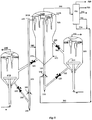
- FIG. 1 is a diagrammatic illustration with the major vessels shown in cross-section comprising of a first riser reactor (200) for adsorption of feed impurities and second riser reactor (100) for cracking of at least a portion of liquid product of the first riser reactor effluent.
- a common stripper cum separator vessel (500) is used for stripping of hydrocarbons from the spent adsorbent as well as spent catalyst and separating the spent adsorbent from the spent cracking catalyst. Regeneration of the spent adsorbent and spent catalyst is carried out separately in adsorbent regenerator (400) and catalyst regenerator (300) respectively.
- adsorbent particles The purpose of using adsorbent particles is to adsorb the CCR, the poisonous metals e.g. vanadium, nickel, sodium, iron and basic nitrogen and sulfur compounds existing in the residual hydrocarbon fractions.
- the hot and low activity adsorbent is added to the bottom of the first riser reactor 200 through standpipe 210 and flow control valve 220.
- Steam introduced through nozzle 230 is used as lift medium to fluidize the adsorbent and carry it upward to the feed injection point 240.
- Fuel gas, ethane, propane, and nitrogen gases, light naphtha can also be used as lift medium to fluidize the adsorbent.
- a heavy residual feedstock is injected at the lower portion 240 of the first riser reactor via feed nozzles.
- the feed can be a mixture of different heavy hydrocarbon feed stocks such as vacuum tower bottom, atmospheric tower bottom, heavy vacuum gas oils, etc. containing higher concentration of metals, CCR, basic nitrogen, etc. Maximum benefit is obtained particularly if the metal level and CCR level of the feed are above 25 ppm and 5 wt% on feed respectively.
- adsorbent particles are having particle size in the range of 200-500 microns but preferably within 300-400 microns.
- the particles density may be within 1500-3000 kg/m 3 and preferably 1800-2600 kg/m 3 and most preferably 2300-2500 kg/m 3 .
- the adsorbent particles mainly consist of the microspheres composed of alumina, silica alumina, silica magnesia, kaolin clay or a mixture thereof having acidic properties or could be totally non acidic.
- these materials have very less acidic cracking activity characterized by Mat activity of less than 25 and surface area of less than 40 m 2 /gm.
- Outlet temperature of the first riser reactor is maintained at 500-600°C by controlling the regenerated adsorbent flow to the first riser reactor 200 from the adsorbent regenerator 400 via stand pipe 210 and control valve 220.
- the adsorbent/oil ratio is varied in the range of 3-10.
- the superficial velocity is maintained in the range of 5-20 m/s typically, which will be sufficient to lift the impurities laden adsorbent particles through the riser.
- the vapor residence time in the first riser reactor may be maintained between 1-5 seconds and preferably between 2-3 seconds depending on the concentration levels of impurities in the feed.
- Heavy organo-metallics, basic nitrogen compounds and precursors to coke are selectively deposited on the adsorbent during vaporization and thermal cracking of the hydrocarbons.
- the combined mixture then passes upward to the first riser reactor terminus 250 followed by cyclone separators 510A and 510B.
- the separated spent adsorbent is collected in the stripper cum separator vessel 500 and vapor product is routed to the fractionation section 700 via overhead line 590.
- Cracked products are separated into various product fractions, from heavy material such as main column bottom withdrawn via line 750 to gaseous products withdrawn via line 710.
- Intermediate fractions include a heavy cycle oil fraction withdrawn via line 740, light cycle oil withdrawn via line 730 and naphtha fraction withdrawn via line 720.
- the stripper cum separator vessel 500 also receives mixture of FCC spent catalyst and hydrocarbon vapor from the second riser reactor 100, wherein, the spent catalyst is separated from the vapor by cyclone separators 520A and 520B
- the hot and active regenerated catalyst is added to the second riser reactor 100 via standpipe 110 and control valve 120 from the catalyst regenerator vessel 300. Steam is introduced through nozzle 130 to act as lift medium to fluidize the catalyst and to transport the catalyst particles in upward direction to the feed injection point 140.
- Conventional state of the art commercial catalyst used in FCC technology may be employed in this invention.
- the preferred catalysts contain large pore zeolites such as Y-zeolites, medium pore zeolites such as ZSM-5 and ZSM-11.
- the particle size of the catalyst remains within 20-200 microns and more preferably 20-170 microns and most preferably 20-100 microns.
- Feedstock is introduced to feed injection point 140 through injection nozzles.
- the feedstock to the second riser reactor is basically a portion of liquid product collected from the fractionation section 700, most preferably a mixture of main column bottom withdrawn via line 750 and heavy cycle oil withdrawn via line 740.
- the naphtha portion withdrawn via line 720 and light cycle oil withdrawn via line 730 are also used along with the heavy cycle oil and main column bottom as feedstock to the second riser reactor, wherein the production of light olefins such as propylene, ethylene, etc are to be maximized.
- outlet temperature of the second riser reactor is maintained at 500-650°C by controlling the regenerated catalyst flow to the second riser reactor 100 from the catalyst regenerator 300 via stand pipe 110 and control valve 120.
- the catalyst/oil ratio is varied in the range of 5-25.
- the superficial velocity is maintained in the range of 5-20 m/s typically, which will be sufficient to lift catalyst particles through the riser.
- the vapor residence time in the riser may be maintained between 1-10 seconds and preferably between 2-5 seconds depending on the desired conversion level.
- Stripping of hydrocarbon vapors and separation of spent adsorbent from the spent catalyst are carried out in the stripper cum separator vessel 500 using steam as a stripping/fluidizing media.
- the superficial velocity of steam in stripper cum separator vessel 500 is maintained in such a way that the spent adsorbent and the spent catalyst are segregated in different layers due to the difference in their physical properties.
- Stripping steam is injected at the bottom of the stripper cum separator via line 570 and/or at different elevations via line 580 to achieve better stripping efficiency.
- 1.0-3.0 tons per 1000 tons of solid flow is the normal rate of total steam flow in the stripper.
- the superficial velocity of stripping gas is maintained in the range of 0.1-0.3 m/s.
- Spent catalyst being lighter in comparison to the spent adsorbent, is segregated at the top portion and enters into stand pipe 550 and finally to catalyst regenerator 300 via control valve 560 for regeneration.
- Spent adsorbent is segregated at the bottom portion and enters into stand pipe 530 and finally to adsorbent regenerator 400 via control valve 540 for regeneration.
- the spent adsorbent containing coke, metals and other impurities is regenerated in the adsorbent regenerator 400 by an oxygen containing gas, such as air, oxygen enriched air that is distributed via an air grid 410.
- the flue gas from this adsorbent regenerator 400 is separated from the entrained adsorbent by cyclone/series of cyclones 420A and 420B and discharged through outlet 430.
- the adsorbent regenerator usually runs on the partial combustion mode under controlled air flow in dense bed fluidization regime.
- the coke burnt from the adsorbent is sufficient to maintain the adsorbent regenerator temperature upto 750°C and preferably between 680-750°C.
- the excess oxygen in the flue gas could be in the range 0-1 vol% and CO/CO 2 may vary in the range 0.2-10 vol/vol.
- CO/CO 2 may vary in the range 0.2-10 vol/vol.
- the spent catalyst is regenerated in the catalyst regenerator 300 by an oxygen containing gas, such as air, oxygen enriched air that is distributed via an air grid 310.
- the flue gas from the catalyst regenerator 300 is separated from the entrained adsorbent by cyclone/series of cyclones 320A and 320B and discharged through outlet 330.
- the excess air is maintained in the regenerator such that full combustion is achieved and the coke on regenerated catalyst is less than 0.1 wt% preferably less than 0.05 wt%.
- Regenerator temperature is maintained in the range 700 to 750°C.
- FIG II (b) gives diagrammatic illustration of the cracking apparatus of the invention. Difference with the embodiment of FIG 1 is that there is provided a vertical "separator plate" within the stripper cum separator 500 which restricts mix-up of the spent catalyst with the spent adsorbent in the vessel thus eliminating the requirement of physical differences between the spent adsorbent and the spent catalyst. Additionally, the stand pipe 550 for taking out the spent catalyst to the catalyst regenerator 300 is located at the bottom of the stripper cum separator vessel 500 instead of at the middle of the vessel 500 as in FIG 1 . The height of the separator plate is such that the spent adsorbent and the spent catalyst are directly and independently collected at the bottom of the stripper cum separator vessel 500 without any possibility of their mix-up.
Landscapes
- Chemical & Material Sciences (AREA)
- Oil, Petroleum & Natural Gas (AREA)
- Chemical Kinetics & Catalysis (AREA)
- Organic Chemistry (AREA)
- Engineering & Computer Science (AREA)
- General Chemical & Material Sciences (AREA)
- Combustion & Propulsion (AREA)
- Dispersion Chemistry (AREA)
- Production Of Liquid Hydrocarbon Mixture For Refining Petroleum (AREA)
Claims (13)
- Vorrichtung für kontinuierliches fluidisiertes katalytisches Cracking zum Umwandeln eines Kohlenwasserstoffausgangsmaterials, das höhere Konzentrationen an Unreinheiten aus Conradson-Kohlenstoffrückstand (CCR), Metall und basischem Stickstoff und Schwefelverbindungen enthält, in leichtere Kohlenwasserstoffe, die folgenden Haupteinheiten umfassend:(i) einen länglichen ersten Steigleitungsreaktor, aufweisend an seiner Basis einen ersten Einlass zum Einführen von regeneriertem Adsorptionsmittel aus einem Adsorptionsreaktor, einen zweiten Einlass zum Einführen von schwerem Kohlenwasserstoffausgangsmaterial mit hohem CCR und anderen Unreinheiten, wie vorstehend erwähnt, für das thermische Cracking des Ausgangsmaterials entlang der ersten Steigleitungsreaktorlänge und einen dritten Einlass zum Einführen von Hochgeschwindigkeitsdampf darin, und einen Auslass an der Oberseite über ein Steigleitungsendstück mit Zyklonseparatoren, die an der Oberseite innerhalb eines gemeinsamen Abstreiferkumulierungsseparators platziert sind, um verbrauchtes Adsorptionsmittel herauszutrennen und gereinigte und einige gecrackte Kohlenwasserstoffdämpfe und Dampfgemisch daraus an eine Fraktioniervorrichtung zu entnehmen,(ii) einen länglichen zweiten Steigleitungsreaktor, aufweisend an seiner Basis einen ersten Einlass zum Einführen von regeneriertem FCC-Katalysator aus einem Katalysatorregenerator, einen zweiten Einlass zum Einführen von gecracktem schweren Ausgangsmaterial, das im Wesentlichen frei von Unreinheiten ist, erhaltbar von der Fraktioniervorrichtung, wie vorstehend erwähnt, für das Cracking in dem zweiten Steigleitungsreaktor durch Kontakt mit dem hochaktiven Katalysator, um einen sehr hohen Ertrag an leichten Olefinen und Destillatprodukten zu erzeugen, und einen dritten Einlass zum Einführen von Hochgeschwindigkeitsdampf darin, und einen Auslass an der Oberseite über ein Steigleitungsendstück mit Zyklonseparatoren, die an der Oberseite innerhalb des gemeinsamen Abstreiferkumulierungsseparators platziert sind, um den verbrauchten Katalysator und die gecrackten leichteren Kohlenwasserstoffdämpfe und Wasserdampf herauszutrennen,(iii) einen gemeinsamen Abstreiferkumulierungsseparator, aufweisend Einspritzmittel an unterschiedlichen Stellen entlang seiner Höhe von der Basis, um Wasserdampf in der Aufwärtsrichtung einzuführen, und mit dem ersten Steigleitungsreaktorendstück der Einheit (i) durch Zyklonseparatoren mit Tauchrohren, die darin nach unten ragen, verbunden, und mit dem zweiten Steigleitungsreaktorendstück der Einheit (ii) durch einen anderen Satz an Zyklonseparatoren mit abwärtigen Tauchrohren darin, eine Zone zum Sammeln des verbrauchten Adsorptionsmittels und des verbrauchten Katalysators für ihre Trennung mit jeweiligen Auslässen dafür durch jeweilige Standrohre und Ventilmittel und zum Transportieren derselben jeweils zu dem Adsorptionsmittelregenerator und dem Katalysatorregenerator, wobei eine vertikale Trennplatte innerhalb des Abstreiferkumulierungsseparators platziert ist, die unabhängiges Sammeln des verbrauchten Katalysators und des verbrauchten Adsorptionsmittels an dem Boden des Abscheiders sicherstellt, ohne eine Vermischung der Materialien, wodurch das Erfordernis eines Unterschieds in den Partikelgrößen und den Dichten von verbrauchtem Katalysator und verbrauchtem Adsorptionsmittel für eine effiziente Trennung entfällt, wobei die Auslässe dafür an dem Boden bereitgestellt sind, um den verbrauchten Katalysator und das verbrauchte Adsorptionsmittel zu den jeweiligen Regeneratoren zu transportieren,(iv) eine Fraktioniervorrichtung zum Durchführen von Fraktionierungskumulierungstrennung unterschiedlicher gecrackter Kohlenwasserstoffe, die von dem gemeinsamen Abstreiferkumulierungsseparator der Einheit (iii) empfangen werden, mit Mitteln zum Sammeln von getrennten, unterschiedlich siedenden Kohlenwasserstoffprodukten, darunter dem schweren Ölboden, verbunden mit dem zweiten Steigleitungsreaktor der Einheit (ii), zur Verwendung als Ausgangsmaterial für das kontinuierliche Crackingverfahren,(v) einen Adsorptionsmittelregenerator zum Reaktivieren des verbrauchten Adsorptionsmittels, aufweisend einen Einlass an seinem Boden zum Einführen von luft- oder sauerstoffhaltigem Gas, einen Einlass im Mittelabschnitt darin in Flusskommunikation mit dem Auslass für das verbrauchte Adsorptionsmittel von dem gemeinsamen Abstreiferkumulierungsseparator durch ein Standrohr und Ventilmittel zum Einführen des verbrauchten Adsorptionsmittels darin, einen Auslass an seinem Boden zum Rückführen und Transportieren des regenerierten oder reaktivierten Adsorptionsmittels durch ein Standrohr und Ventilmittel zu dem ersten Steigleitungsreaktor der Einheit (i), und einen anderen Auslass an seiner Oberseite für die Entsorgung des Rauchgases; wobei der Adsorptionsmittelregenerator zusätzlich Zyklonseparatoren darin an der Oberseite aufweist, um das Rauchgas in eingeschlossenes Adsorptionsmittel zu trennen, und(vi) einen Katalysatorregenerator zum Regenerieren des Katalysators, aufweisend einen Einlass an seiner Basis zum Einführen von luft- oder sauerstoffhaltigem Gas, einen Einlass im Mittelabschnitt entlang seiner Höhe zum Einführen des verbrauchten Katalysators darin von dem gemeinsamen Abstreiferkumulierungsseparator der Einheit (iii) durch ein Standrohr und Ventilmittel, einen Auslass an seiner Basis zum Rückführen und Transportieren des regenerierten Katalysators über ein Standrohr und Ventilmittel zu dem zweiten Steigleitungsreaktor der Einheit (ii), und einen anderen Auslass an seiner Oberseite für die Entsorgung von Rauchgas; wobei der Katalysatorregenerator zusätzlich Zyklonseparatoren darin an der Oberseite aufweist, um das Rauchgas von dem eingeschlossenen Katalysator zu trennen.
- Vorrichtung nach Anspruch 1, wobei sich die Zone zum Sammeln von verbrauchtem Adsorptionsmittel und verbrauchtem Katalysator an dem Boden des gemeinsamen Abstreiferkumulierungsseparators befindet, wobei das verbrauchte Adsorptionsmittel und der verbrauchte Katalysator als separate Schichten erhalten werden, wobei das schwerere Adsorptionsmittel an dem Boden gesammelt und davon durch den Bodenauslass zu dem Adsorptionsmittelregenerator transportiert wird und der leichtere Katalysator in der höheren Schicht gesammelt wird, von der aus er durch den Auslass dafür an einer höheren Ebene in dem Abstreiferkumulierungsseparator zu dem Katalysatorregenerator transportiert wird.
- Verfahren für kontinuierliches fluidisiertes katalytisches Cracking (FCC) zum Umwandeln eines Kohlenwasserstoffausgangsmaterials, das höhere Konzentrationen an Unreinheiten enthält, wie zum Beispiel Unreinheiten aus Conradson-Kohlenstoffrückstand (CCR), Metall und basischem Stickstoff und Schwefelverbindungen, in leichtere Kohlenwasserstoffprodukte, indem mehrere längliche Steigleitungsreaktoren, ein gemeinsamer Abstreiferkumulierungsseparator, eine gemeinsame Fraktioniervorrichtung und mehrere Regeneratoren eingesetzt werden, um verwendetes Adsorptionsmittel und verwendeten Katalysator gleichzeitig darin zu regenerieren, die folgenden Schritte umfassend:(a) Kontaktieren des Ausgangsmaterials mit heißem Adsorptionsmittel, zugeführt von dem Adsorptionsmittelregenerator in dem ersten Steigleitungsreaktor, wobei das Adsorptionsmittel unter Verwendung von Hubmedium zu der Ausgangsmaterialeinspritzzone angehoben wird, wo das Ausgangsmaterial verdampft, gereinigt und einem leichten Cracking unterzogen wird, um dampfförmige Kohlenwasserstoffprodukte zu erhalten, die im Wesentlichen frei von Unreinheiten sind, umfassend eine Naphthafraktion, eine leichtere gasförmige Kohlenwasserstoffmaterialfraktion, leichtes Rückführöl, schweres Rückführöl und höhersiedende Materialien als das schwere Rückführöl, und mit Unreinheiten beladene Adsorptionspartikel und Trennen der unreinen Adsorptionspartikel von den Kohlenwasserstoffen unter Verwendung eines Steigleitungsendstücks mit Zyklonseparatoren innerhalb der gemeinsamen Abstreiferkumulierungsseparatorvorrichtung, während gleichzeitig Folgendes durchgeführt wird:(b) starkes Cracken von zumindest einem Teil an Flüssigprodukt, umfassend gecracktes schweres Rückführöl und höhersiedendes Material als schweres Rückführöl oder von der gemeinsamen Fraktioniervorrichtung erhaltene Gemische in einem zweiten Steigleitungsreaktor in Anwesenheit von regeneriertem Crackingkatalysator, zugeführt von dem Katalysatorregenerator, um dampfförmige Umwandlungsprodukte zu erhalten, umfassend Material im Benzinsiedebereich, das einen hohen aromatischen Gehalt und eine hohe Oktanzahl aufweist, und leichteres gasförmiges Kohlenwasserstoffmaterial, leichtes Rückführölmaterial und Trennen der Katalysatorpartikel von den dampfförmigen Umwandlungsprodukten in dem dafür bereitgestellten Zyklonseparatoren innerhalb der gemeinsamen Abstreiferkumulierungsseparatorvorrichtung, die in Schritt (a) verwendet wird,(c) Kombinieren der dampfförmigen Umwandlungsprodukte aus den zweiten und ersten Steigleitungsreaktoren in einer gemeinsamen Abscheidezone, wobei darin eingeschlossenes Adsorptionsmittel und eingeschlossene Katalysatorpartikel von dampfförmigen Produkten in jeweiligen Steigleitungsendstücken getrennt werden und die kombinierten Umwandlungsprodukte zu einer gemeinsamen Fraktioniervorrichtung weitergeleitet werden, die eine Zone zur fraktionierten Destillation enthält, um zumindest eine Materialfraktion im Benzinsiedebereich, eine höhere gasförmige Kohlenwasserstoffmaterialfraktion, eine Materialfraktion im Siedebereich von leichtem Rückführöl, eine Materialfraktion im Siedebereich von schwerem Rückführöl und Schlammöl beinhaltend zurückzugewinnen,(d) Trennen des verbrauchten Adsorptionsmittels und verbrauchten Katalysators in dem gemeinsamen Abstreiferkumulierungsseparatorbehälter, wobei die Trennung des verbrauchten Adsorptionsmittels und des verbrauchten Katalysators durchgeführt wird, indem eine vertikale Trennplatte innerhalb des gemeinsamen Abstreiferkumulierungsseparatorbehälters bereitgestellt wird, mit der das verbrauchte Adsorptionsmittel und der verbrauchte Katalysator unabhängig und separat gesammelt werden, ohne eine Möglichkeit der Vermischung der beiden in dem Abstreiferkumulierungsseparator,(e) Entziehen des getrennten verbrauchten Adsorptionsmittels und verbrauchten Katalysators aus dem gemeinsamen Abstreiferkumulierungsseparatorbehälter und Übertragen derselben auf jeweilige Regeneratoren, um den verbrauchten Katalysator und das verbrauchte Adsorptionsmittel zu regenerieren,(f) separates Regenerieren des verbrauchten Adsorptionsmittels und des verbrauchten Katalysators in den jeweiligen Regeneratoren durch Verbrennen von Unreinheiten darin durch ein sauerstoffhaltiges Gas bei erhöhter Temperatur, und(g) Übertragen des regenerierten Adsorptionsmittels von dem Adsorptionsmittelregenerator auf den ersten Steigleitungsreaktor und Übertragen des regenerierten Katalysators von dem Katalysatorregenerator auf den zweiten Steigleitungsreaktor, um den kontinuierlichen Crackingzyklus beizubehalten.
- Verfahren nach Anspruch 3, wobei die Trennung des verbrauchten Adsorptionsmittels und verbrauchten Katalysators aus Schritt (d) durchgeführt wird, indem ausreichend oberflächliche Geschwindigkeit an fluidisierungsmediumartigem Wasserdampf beibehalten wird, der zu der Segregation des verbrauchten Adsorptionsmittels und des verbrauchten Katalysators in zwei unterschiedliche Schichten führt, abhängig von der Partikelgröße, Dichte und Unterschieden in ihrer Mindestfluidisierungsgeschwindigkeit, durch Verwenden der Fluidisierungsmedien, sodass sich schwerere Partikel an verkoktem Adsorptionsmittel an dem Boden des gemeinsamen Abstreiferkumulierungsseparators absetzen und sich die leichteren Partikel an verbrauchtem Katalysator an der oberen Stelle des gemeinsamen Abstreiferkumulierungsseparators absetzen, während alle abstreifbaren interstitiellen Kohlenwasserstoffe von dem verbrauchten Crackingkatalysator und verbrauchten Adsorptionsmittelgemisch durch den Abstreiferkumulierungsseparator abgestreift werden, wobei die segregierten Schichten an verbrauchtem Katalysator und verbrauchtem Adsorptionsmittel über jeweilige Standrohre und Steuerventile separat zu jeweiligen Regeneratoren transportiert werden.
- Verfahren nach Anspruch 3, wobei gecracktes Naphtha und leichtes Rückführöl zusammen mit schwerem Rückführöl und Hauptsäulenboden als Ausgangsmaterial zu dem zweiten Steigleitungsreaktor verwendet werden, um die Produktion von leichten Olefinen wie zum Beispiel Propylen, Ethylen usw. zu maximieren.
- Verfahren nach Anspruch 3, wobei das Adsorptionsmittel aus der Gruppe ausgewählt ist, die aus Magnesiumoxid, Siliziumdioxid-Magnesiumoxid, Kaolinton, Aluminiumoxid-Siliziumoxid-Aluminiumoxid und einem Gemisch davon besteht, das saure und nichtsaure Eigenschaften aufweist.
- Verfahren nach Anspruch 3, wobei das Adsorptionsmittel eine Partikelgröße aufweist, die von 200-500 Mikrometern reicht, mit einer Partikeldichte, die von 1500 bis 3000 kg/m3 reicht, während die Partikelgröße des Katalysators in der Spanne von 20 bis 200 Mikrometern gehalten wird, mit einer Partikeldichte, die von 1200 bis 1800 kg/m3 reicht.
- Verfahren nach Anspruch 3, wobei das Kohlenwasserstoffausgangsmaterial einen Nickelgehalt bis zu 50 ppm und Vanadiumgehalt bis zu 100 ppm aufweist.
- Verfahren nach Anspruch 3, wobei das mit Unreinheiten beladene Adsorptionsmittel Metalle bis zu 75000 ppm enthält.
- Verfahren nach Anspruch 3, wobei der Katalysator Partikel von REY/USY-Zeolith, formselektives Pentasil-Zeolith und einen Co-Promoter enthält.
- Verfahren nach Anspruch 3, wobei der erste Steigleitungsreaktor bei einer Temperatur betrieben wird, die von 500 bis 600 °C reicht und der zweite Steigleitungsreaktor bei einer Temperatur betrieben wird, die von 500 bis 650 °C reicht.
- Verfahren nach Anspruch 3, wobei der erste Steigleitungsreaktor ein Verhältnis von Adsorptionsmittel zu Gesamtkohlenwasserstoff in einer Spanne von 3:1 bis 10:1 wt/wt aufweist und der zweite Steigleitungsreaktor ein Verhältnis von Katalysator zu Gesamtkohlenwasserstoff in einer Spanne von 5:1 bis 25:1 wt/wt aufweist.
- Verfahren nach Anspruch 3, wobei leichtere Produkte Ethylen, Propylen, C4-Olefine und Hochoktanbenzin beinhalten.
Applications Claiming Priority (2)
| Application Number | Priority Date | Filing Date | Title |
|---|---|---|---|
| IN748KO2010 | 2010-07-08 | ||
| PCT/IN2011/000443 WO2012004807A1 (en) | 2010-07-08 | 2011-07-04 | Multi riser resid catalytic cracking process and apparatus |
Publications (2)
| Publication Number | Publication Date |
|---|---|
| EP2591072A1 EP2591072A1 (de) | 2013-05-15 |
| EP2591072B1 true EP2591072B1 (de) | 2019-03-13 |
Family
ID=44509518
Family Applications (1)
| Application Number | Title | Priority Date | Filing Date |
|---|---|---|---|
| EP11741291.6A Active EP2591072B1 (de) | 2010-07-08 | 2011-07-04 | Katalytisches crackingverfahren mit mehreren steigleitungen für rückstande und vorrichtung |
Country Status (4)
| Country | Link |
|---|---|
| US (1) | US9771526B2 (de) |
| EP (1) | EP2591072B1 (de) |
| TR (1) | TR201907926T4 (de) |
| WO (1) | WO2012004807A1 (de) |
Families Citing this family (14)
| Publication number | Priority date | Publication date | Assignee | Title |
|---|---|---|---|---|
| WO2011121612A1 (en) * | 2010-03-31 | 2011-10-06 | Indian Oil Corporation Limited | Method and apparatus for catalytic cracking |
| CN103785550B (zh) * | 2012-10-29 | 2017-03-01 | 中国石油化工股份有限公司 | 气流式颗粒分选器和流化床反应器及其应用 |
| US20150136647A1 (en) * | 2013-11-21 | 2015-05-21 | Kellogg Brown & Root Llc | Reactor and main fractionator configuration for producing diesel |
| US9669373B2 (en) | 2014-12-12 | 2017-06-06 | Uop Llc | Apparatus and process for heating catalyst from a reactor |
| CN105820830A (zh) * | 2015-01-06 | 2016-08-03 | 李群柱 | 一种冷再生催化剂循环方法及其装置 |
| US9777228B2 (en) * | 2015-06-30 | 2017-10-03 | Uop Llc | Process for cracking hydrocarbons to make diesel |
| CN106140036A (zh) * | 2016-08-31 | 2016-11-23 | 安徽金禾实业股份有限公司 | 一种三聚氰胺生产中流化床出风口分离装置 |
| US11173482B2 (en) * | 2019-05-28 | 2021-11-16 | Saudi Arabian Oil Company | Combustion of spent adsorbents containing HPNA compounds in FCC catalyst regenerator |
| TWI865554B (zh) * | 2019-07-02 | 2024-12-11 | 美商魯瑪斯科技有限責任公司 | 流體催化裂解方法及設備 |
| CN114222805A (zh) * | 2019-08-05 | 2022-03-22 | 沙特基础工业全球技术公司 | 高密度流化床系统 |
| US12012556B2 (en) | 2019-08-05 | 2024-06-18 | Sabic Global Technologies B.V. | Dense phase riser to maximize light olefins yields for naphtha catalytic cracking |
| CN111892943B (zh) * | 2020-05-12 | 2025-02-14 | 浙江美福石油化工有限责任公司 | 一种用于混合芳烃制备丙烯的提升管回炼装置 |
| US20240017228A1 (en) * | 2022-07-14 | 2024-01-18 | Uop Llc | Process and apparatus for separating catalyst from product gas |
| JP2026504030A (ja) * | 2023-01-09 | 2026-02-03 | 中国石油化工股▲ふん▼有限公司 | 流動触媒転化システムおよびその応用 |
Family Cites Families (18)
| Publication number | Priority date | Publication date | Assignee | Title |
|---|---|---|---|---|
| US1484A (en) | 1840-01-29 | Improvement in brick-machines | ||
| US3803024A (en) * | 1972-03-16 | 1974-04-09 | Chevron Res | Catalytic cracking process |
| US4875994A (en) | 1988-06-10 | 1989-10-24 | Haddad James H | Process and apparatus for catalytic cracking of residual oils |
| US5021222A (en) | 1988-10-18 | 1991-06-04 | Mobil Oil Corporation | Resid cracking apparatus |
| US4895637A (en) | 1988-10-18 | 1990-01-23 | Mobil Oil Corporation | Resid cracking process and apparatus |
| US5059302A (en) | 1989-05-16 | 1991-10-22 | Engelhard Corporation | Method and apparatus for the fluid catalytic cracking of hydrocarbon feed employing a separable mixture of catalyst and sorbent particles |
| US5196172A (en) | 1989-05-16 | 1993-03-23 | Engelhard Corporation | Apparatus for the fluid catalytic cracking of hydrocarbon feed employing a separable mixture of catalyst and sorbent particles |
| US5110775A (en) | 1990-12-28 | 1992-05-05 | Mobil Oil Corporation | Two stage combustion process for cracking catalyst regeneration |
| US5286691A (en) | 1992-10-26 | 1994-02-15 | Mobil Oil Coproration | Demetallation in FCC regenerator |
| US5324417A (en) | 1993-05-25 | 1994-06-28 | Mobil Oil Corporation | Processing waste over spent FCC catalyst |
| US5919352A (en) | 1995-07-17 | 1999-07-06 | Exxon Research And Engineering Co. | Integrated residua upgrading and fluid catalytic cracking |
| EP1013743B1 (de) | 1998-12-21 | 2005-02-02 | INDIAN OIL CORPORATION Ltd. | Fluidkatalytisch Krachverfahren |
| US6656344B1 (en) | 1998-12-23 | 2003-12-02 | Marri Rama Rao | Fluidized catalytic cracking process |
| US20020003103A1 (en) | 1998-12-30 | 2002-01-10 | B. Erik Henry | Fluid cat cracking with high olefins prouduction |
| EP1190019A1 (de) | 2000-02-16 | 2002-03-27 | Indian Oil Corporation Limited | Mehrstufiger selektiver cracking-prozess und vorrichtung zur erzeugung hoher ausbeutenan mitteldestillaten aus schwerölen |
| DE10219863B4 (de) | 2002-05-03 | 2014-03-27 | Indian Oil Corporation Limited | Rückstandscrackvorrichtung mit Katalysator- und Adsorptionsmittelregeneratoren und Verfahren hierfür |
| US7381322B2 (en) | 2002-05-08 | 2008-06-03 | Indian Oil Corporation Limited | Resid cracking apparatus with catalyst and adsorbent regenerators and a process thereof |
| US7611622B2 (en) * | 2006-12-29 | 2009-11-03 | Kellogg Brown & Root Llc | FCC process for converting C3/C4 feeds to olefins and aromatics |
-
2011
- 2011-07-04 EP EP11741291.6A patent/EP2591072B1/de active Active
- 2011-07-04 WO PCT/IN2011/000443 patent/WO2012004807A1/en not_active Ceased
- 2011-07-04 TR TR2019/07926T patent/TR201907926T4/tr unknown
- 2011-07-04 US US13/808,852 patent/US9771526B2/en active Active
Non-Patent Citations (1)
| Title |
|---|
| None * |
Also Published As
| Publication number | Publication date |
|---|---|
| TR201907926T4 (tr) | 2019-06-21 |
| EP2591072A1 (de) | 2013-05-15 |
| US9771526B2 (en) | 2017-09-26 |
| WO2012004807A1 (en) | 2012-01-12 |
| US20130168289A1 (en) | 2013-07-04 |
Similar Documents
| Publication | Publication Date | Title |
|---|---|---|
| US9771526B2 (en) | Multi riser resid catalytic cracking process and apparatus | |
| US4434044A (en) | Method for recovering sulfur oxides from CO-rich flue gas | |
| US4435279A (en) | Method and apparatus for converting oil feeds | |
| US4331533A (en) | Method and apparatus for cracking residual oils | |
| US4336160A (en) | Method and apparatus for cracking residual oils | |
| US4427539A (en) | Demetallizing and decarbonizing heavy residual oil feeds | |
| US3821103A (en) | Conversion of sulfur contaminated hydrocarbons | |
| US4569753A (en) | Oil upgrading by thermal and catalytic cracking | |
| EP0171460A1 (de) | Verfahren zur katalytischen Spaltung von Residualölen mit Trockengas als Auftriebgas in einem Steigrohrreaktor | |
| EP3077484B1 (de) | Integriertes verfahren zur entasphaltierung und zum katalytischen cracken zur herstellung von leichten olefinen | |
| EP1013743B1 (de) | Fluidkatalytisch Krachverfahren | |
| US7008595B2 (en) | Resid cracking apparatus with catalyst and adsorbent regenerators and a process thereof | |
| US7381322B2 (en) | Resid cracking apparatus with catalyst and adsorbent regenerators and a process thereof | |
| US6656344B1 (en) | Fluidized catalytic cracking process | |
| TW202111101A (zh) | 流體催化裂解方法以及用於使輕質烯烴產率最大化及其他應用之裝置 | |
| KR20220156569A (ko) | 유동 접촉 분해 공정 및 장비를 통한 원유로부터의 경질 올레핀의 제조 | |
| US4894141A (en) | Combination process for upgrading residual oils | |
| CA1239106A (en) | Addition of water to regeneration air | |
| US4206038A (en) | Hydrogen recovery from gaseous product of fluidized catalytic cracking | |
| CN107828442B (zh) | 用于在流化催化裂化工艺中的增强的污染物除去的方法和装置 | |
| JPH04220491A (ja) | 流出物中に存在するオレフィンのオリゴマー化またはトリマー化を伴う接触クラッキング方法 | |
| US4915820A (en) | Removal of coke and metals from carbo-metallic oils | |
| EP0066387B1 (de) | Kombinationsverfahren für die Verbesserung von Residualölen | |
| US4525268A (en) | Combination process for upgrading residual oils | |
| CA1156590A (en) | Method and apparatus for cracking residual oils |
Legal Events
| Date | Code | Title | Description |
|---|---|---|---|
| PUAI | Public reference made under article 153(3) epc to a published international application that has entered the european phase |
Free format text: ORIGINAL CODE: 0009012 |
|
| 17P | Request for examination filed |
Effective date: 20130208 |
|
| AK | Designated contracting states |
Kind code of ref document: A1 Designated state(s): AL AT BE BG CH CY CZ DE DK EE ES FI FR GB GR HR HU IE IS IT LI LT LU LV MC MK MT NL NO PL PT RO RS SE SI SK SM TR |
|
| DAX | Request for extension of the european patent (deleted) | ||
| 17Q | First examination report despatched |
Effective date: 20140116 |
|
| STAA | Information on the status of an ep patent application or granted ep patent |
Free format text: STATUS: EXAMINATION IS IN PROGRESS |
|
| RIC1 | Information provided on ipc code assigned before grant |
Ipc: C10G 25/09 20060101ALI20181008BHEP Ipc: C10G 25/12 20060101ALI20181008BHEP Ipc: C10G 55/08 20060101ALI20181008BHEP Ipc: C10G 55/06 20060101ALI20181008BHEP Ipc: C10G 51/02 20060101ALI20181008BHEP Ipc: C10G 70/04 20060101ALI20181008BHEP Ipc: B01J 8/00 20060101ALI20181008BHEP Ipc: B01J 8/26 20060101ALI20181008BHEP Ipc: B01J 8/32 20060101ALI20181008BHEP Ipc: C10G 11/18 20060101AFI20181008BHEP Ipc: B01J 8/18 20060101ALI20181008BHEP |
|
| GRAP | Despatch of communication of intention to grant a patent |
Free format text: ORIGINAL CODE: EPIDOSNIGR1 |
|
| STAA | Information on the status of an ep patent application or granted ep patent |
Free format text: STATUS: GRANT OF PATENT IS INTENDED |
|
| INTG | Intention to grant announced |
Effective date: 20181121 |
|
| GRAS | Grant fee paid |
Free format text: ORIGINAL CODE: EPIDOSNIGR3 |
|
| GRAA | (expected) grant |
Free format text: ORIGINAL CODE: 0009210 |
|
| STAA | Information on the status of an ep patent application or granted ep patent |
Free format text: STATUS: THE PATENT HAS BEEN GRANTED |
|
| AK | Designated contracting states |
Kind code of ref document: B1 Designated state(s): AL AT BE BG CH CY CZ DE DK EE ES FI FR GB GR HR HU IE IS IT LI LT LU LV MC MK MT NL NO PL PT RO RS SE SI SK SM TR |
|
| REG | Reference to a national code |
Ref country code: GB Ref legal event code: FG4D |
|
| REG | Reference to a national code |
Ref country code: CH Ref legal event code: EP Ref country code: AT Ref legal event code: REF Ref document number: 1107651 Country of ref document: AT Kind code of ref document: T Effective date: 20190315 |
|
| REG | Reference to a national code |
Ref country code: IE Ref legal event code: FG4D |
|
| REG | Reference to a national code |
Ref country code: DE Ref legal event code: R096 Ref document number: 602011057105 Country of ref document: DE |
|
| REG | Reference to a national code |
Ref country code: RO Ref legal event code: EPE |
|
| REG | Reference to a national code |
Ref country code: NL Ref legal event code: MP Effective date: 20190313 |
|
| REG | Reference to a national code |
Ref country code: LT Ref legal event code: MG4D |
|
| PG25 | Lapsed in a contracting state [announced via postgrant information from national office to epo] |
Ref country code: LT Free format text: LAPSE BECAUSE OF FAILURE TO SUBMIT A TRANSLATION OF THE DESCRIPTION OR TO PAY THE FEE WITHIN THE PRESCRIBED TIME-LIMIT Effective date: 20190313 Ref country code: SE Free format text: LAPSE BECAUSE OF FAILURE TO SUBMIT A TRANSLATION OF THE DESCRIPTION OR TO PAY THE FEE WITHIN THE PRESCRIBED TIME-LIMIT Effective date: 20190313 Ref country code: NO Free format text: LAPSE BECAUSE OF FAILURE TO SUBMIT A TRANSLATION OF THE DESCRIPTION OR TO PAY THE FEE WITHIN THE PRESCRIBED TIME-LIMIT Effective date: 20190613 Ref country code: FI Free format text: LAPSE BECAUSE OF FAILURE TO SUBMIT A TRANSLATION OF THE DESCRIPTION OR TO PAY THE FEE WITHIN THE PRESCRIBED TIME-LIMIT Effective date: 20190313 |
|
| PG25 | Lapsed in a contracting state [announced via postgrant information from national office to epo] |
Ref country code: HR Free format text: LAPSE BECAUSE OF FAILURE TO SUBMIT A TRANSLATION OF THE DESCRIPTION OR TO PAY THE FEE WITHIN THE PRESCRIBED TIME-LIMIT Effective date: 20190313 Ref country code: NL Free format text: LAPSE BECAUSE OF FAILURE TO SUBMIT A TRANSLATION OF THE DESCRIPTION OR TO PAY THE FEE WITHIN THE PRESCRIBED TIME-LIMIT Effective date: 20190313 Ref country code: LV Free format text: LAPSE BECAUSE OF FAILURE TO SUBMIT A TRANSLATION OF THE DESCRIPTION OR TO PAY THE FEE WITHIN THE PRESCRIBED TIME-LIMIT Effective date: 20190313 Ref country code: GR Free format text: LAPSE BECAUSE OF FAILURE TO SUBMIT A TRANSLATION OF THE DESCRIPTION OR TO PAY THE FEE WITHIN THE PRESCRIBED TIME-LIMIT Effective date: 20190614 Ref country code: BG Free format text: LAPSE BECAUSE OF FAILURE TO SUBMIT A TRANSLATION OF THE DESCRIPTION OR TO PAY THE FEE WITHIN THE PRESCRIBED TIME-LIMIT Effective date: 20190613 Ref country code: RS Free format text: LAPSE BECAUSE OF FAILURE TO SUBMIT A TRANSLATION OF THE DESCRIPTION OR TO PAY THE FEE WITHIN THE PRESCRIBED TIME-LIMIT Effective date: 20190313 |
|
| PG25 | Lapsed in a contracting state [announced via postgrant information from national office to epo] |
Ref country code: SK Free format text: LAPSE BECAUSE OF FAILURE TO SUBMIT A TRANSLATION OF THE DESCRIPTION OR TO PAY THE FEE WITHIN THE PRESCRIBED TIME-LIMIT Effective date: 20190313 Ref country code: PT Free format text: LAPSE BECAUSE OF FAILURE TO SUBMIT A TRANSLATION OF THE DESCRIPTION OR TO PAY THE FEE WITHIN THE PRESCRIBED TIME-LIMIT Effective date: 20190713 Ref country code: AL Free format text: LAPSE BECAUSE OF FAILURE TO SUBMIT A TRANSLATION OF THE DESCRIPTION OR TO PAY THE FEE WITHIN THE PRESCRIBED TIME-LIMIT Effective date: 20190313 Ref country code: ES Free format text: LAPSE BECAUSE OF FAILURE TO SUBMIT A TRANSLATION OF THE DESCRIPTION OR TO PAY THE FEE WITHIN THE PRESCRIBED TIME-LIMIT Effective date: 20190313 Ref country code: CZ Free format text: LAPSE BECAUSE OF FAILURE TO SUBMIT A TRANSLATION OF THE DESCRIPTION OR TO PAY THE FEE WITHIN THE PRESCRIBED TIME-LIMIT Effective date: 20190313 Ref country code: EE Free format text: LAPSE BECAUSE OF FAILURE TO SUBMIT A TRANSLATION OF THE DESCRIPTION OR TO PAY THE FEE WITHIN THE PRESCRIBED TIME-LIMIT Effective date: 20190313 |
|
| PG25 | Lapsed in a contracting state [announced via postgrant information from national office to epo] |
Ref country code: SM Free format text: LAPSE BECAUSE OF FAILURE TO SUBMIT A TRANSLATION OF THE DESCRIPTION OR TO PAY THE FEE WITHIN THE PRESCRIBED TIME-LIMIT Effective date: 20190313 Ref country code: PL Free format text: LAPSE BECAUSE OF FAILURE TO SUBMIT A TRANSLATION OF THE DESCRIPTION OR TO PAY THE FEE WITHIN THE PRESCRIBED TIME-LIMIT Effective date: 20190313 |
|
| REG | Reference to a national code |
Ref country code: DE Ref legal event code: R097 Ref document number: 602011057105 Country of ref document: DE |
|
| PG25 | Lapsed in a contracting state [announced via postgrant information from national office to epo] |
Ref country code: IS Free format text: LAPSE BECAUSE OF FAILURE TO SUBMIT A TRANSLATION OF THE DESCRIPTION OR TO PAY THE FEE WITHIN THE PRESCRIBED TIME-LIMIT Effective date: 20190713 |
|
| PLBE | No opposition filed within time limit |
Free format text: ORIGINAL CODE: 0009261 |
|
| STAA | Information on the status of an ep patent application or granted ep patent |
Free format text: STATUS: NO OPPOSITION FILED WITHIN TIME LIMIT |
|
| PG25 | Lapsed in a contracting state [announced via postgrant information from national office to epo] |
Ref country code: DK Free format text: LAPSE BECAUSE OF FAILURE TO SUBMIT A TRANSLATION OF THE DESCRIPTION OR TO PAY THE FEE WITHIN THE PRESCRIBED TIME-LIMIT Effective date: 20190313 |
|
| 26N | No opposition filed |
Effective date: 20191216 |
|
| PG25 | Lapsed in a contracting state [announced via postgrant information from national office to epo] |
Ref country code: MC Free format text: LAPSE BECAUSE OF FAILURE TO SUBMIT A TRANSLATION OF THE DESCRIPTION OR TO PAY THE FEE WITHIN THE PRESCRIBED TIME-LIMIT Effective date: 20190313 Ref country code: SI Free format text: LAPSE BECAUSE OF FAILURE TO SUBMIT A TRANSLATION OF THE DESCRIPTION OR TO PAY THE FEE WITHIN THE PRESCRIBED TIME-LIMIT Effective date: 20190313 |
|
| REG | Reference to a national code |
Ref country code: CH Ref legal event code: PL |
|
| GBPC | Gb: european patent ceased through non-payment of renewal fee |
Effective date: 20190704 |
|
| REG | Reference to a national code |
Ref country code: BE Ref legal event code: MM Effective date: 20190731 |
|
| PG25 | Lapsed in a contracting state [announced via postgrant information from national office to epo] |
Ref country code: GB Free format text: LAPSE BECAUSE OF NON-PAYMENT OF DUE FEES Effective date: 20190704 |
|
| PG25 | Lapsed in a contracting state [announced via postgrant information from national office to epo] |
Ref country code: LI Free format text: LAPSE BECAUSE OF NON-PAYMENT OF DUE FEES Effective date: 20190731 Ref country code: CH Free format text: LAPSE BECAUSE OF NON-PAYMENT OF DUE FEES Effective date: 20190731 Ref country code: LU Free format text: LAPSE BECAUSE OF NON-PAYMENT OF DUE FEES Effective date: 20190704 Ref country code: BE Free format text: LAPSE BECAUSE OF NON-PAYMENT OF DUE FEES Effective date: 20190731 |
|
| PG25 | Lapsed in a contracting state [announced via postgrant information from national office to epo] |
Ref country code: FR Free format text: LAPSE BECAUSE OF NON-PAYMENT OF DUE FEES Effective date: 20190731 |
|
| PG25 | Lapsed in a contracting state [announced via postgrant information from national office to epo] |
Ref country code: IE Free format text: LAPSE BECAUSE OF NON-PAYMENT OF DUE FEES Effective date: 20190704 |
|
| PG25 | Lapsed in a contracting state [announced via postgrant information from national office to epo] |
Ref country code: CY Free format text: LAPSE BECAUSE OF FAILURE TO SUBMIT A TRANSLATION OF THE DESCRIPTION OR TO PAY THE FEE WITHIN THE PRESCRIBED TIME-LIMIT Effective date: 20190313 |
|
| PG25 | Lapsed in a contracting state [announced via postgrant information from national office to epo] |
Ref country code: HU Free format text: LAPSE BECAUSE OF FAILURE TO SUBMIT A TRANSLATION OF THE DESCRIPTION OR TO PAY THE FEE WITHIN THE PRESCRIBED TIME-LIMIT; INVALID AB INITIO Effective date: 20110704 Ref country code: MT Free format text: LAPSE BECAUSE OF FAILURE TO SUBMIT A TRANSLATION OF THE DESCRIPTION OR TO PAY THE FEE WITHIN THE PRESCRIBED TIME-LIMIT Effective date: 20190313 |
|
| REG | Reference to a national code |
Ref country code: AT Ref legal event code: UEP Ref document number: 1107651 Country of ref document: AT Kind code of ref document: T Effective date: 20190313 |
|
| PG25 | Lapsed in a contracting state [announced via postgrant information from national office to epo] |
Ref country code: MK Free format text: LAPSE BECAUSE OF FAILURE TO SUBMIT A TRANSLATION OF THE DESCRIPTION OR TO PAY THE FEE WITHIN THE PRESCRIBED TIME-LIMIT Effective date: 20190313 |
|
| PGFP | Annual fee paid to national office [announced via postgrant information from national office to epo] |
Ref country code: DE Payment date: 20250730 Year of fee payment: 15 |
|
| PGFP | Annual fee paid to national office [announced via postgrant information from national office to epo] |
Ref country code: TR Payment date: 20250704 Year of fee payment: 15 Ref country code: IT Payment date: 20250729 Year of fee payment: 15 |
|
| PGFP | Annual fee paid to national office [announced via postgrant information from national office to epo] |
Ref country code: AT Payment date: 20250728 Year of fee payment: 15 |
|
| PGFP | Annual fee paid to national office [announced via postgrant information from national office to epo] |
Ref country code: RO Payment date: 20250704 Year of fee payment: 15 |