EP2590857B1 - Linkage for guiding a flexible cable - Google Patents
Linkage for guiding a flexible cable Download PDFInfo
- Publication number
- EP2590857B1 EP2590857B1 EP11732504.3A EP11732504A EP2590857B1 EP 2590857 B1 EP2590857 B1 EP 2590857B1 EP 11732504 A EP11732504 A EP 11732504A EP 2590857 B1 EP2590857 B1 EP 2590857B1
- Authority
- EP
- European Patent Office
- Prior art keywords
- arm
- linkage
- distal
- control surface
- distal arm
- Prior art date
- Legal status (The legal status is an assumption and is not a legal conclusion. Google has not performed a legal analysis and makes no representation as to the accuracy of the status listed.)
- Active
Links
Images





Classifications
-
- B—PERFORMING OPERATIONS; TRANSPORTING
- B64—AIRCRAFT; AVIATION; COSMONAUTICS
- B64C—AEROPLANES; HELICOPTERS
- B64C9/00—Adjustable control surfaces or members, e.g. rudders
- B64C9/14—Adjustable control surfaces or members, e.g. rudders forming slots
- B64C9/22—Adjustable control surfaces or members, e.g. rudders forming slots at the front of the wing
-
- F—MECHANICAL ENGINEERING; LIGHTING; HEATING; WEAPONS; BLASTING
- F16—ENGINEERING ELEMENTS AND UNITS; GENERAL MEASURES FOR PRODUCING AND MAINTAINING EFFECTIVE FUNCTIONING OF MACHINES OR INSTALLATIONS; THERMAL INSULATION IN GENERAL
- F16C—SHAFTS; FLEXIBLE SHAFTS; ELEMENTS OR CRANKSHAFT MECHANISMS; ROTARY BODIES OTHER THAN GEARING ELEMENTS; BEARINGS
- F16C7/00—Connecting-rods or like links pivoted at both ends; Construction of connecting-rod heads
- F16C7/02—Constructions of connecting-rods with constant length
-
- Y—GENERAL TAGGING OF NEW TECHNOLOGICAL DEVELOPMENTS; GENERAL TAGGING OF CROSS-SECTIONAL TECHNOLOGIES SPANNING OVER SEVERAL SECTIONS OF THE IPC; TECHNICAL SUBJECTS COVERED BY FORMER USPC CROSS-REFERENCE ART COLLECTIONS [XRACs] AND DIGESTS
- Y10—TECHNICAL SUBJECTS COVERED BY FORMER USPC
- Y10T—TECHNICAL SUBJECTS COVERED BY FORMER US CLASSIFICATION
- Y10T74/00—Machine element or mechanism
- Y10T74/21—Elements
- Y10T74/2142—Pitmans and connecting rods
Definitions
- the present invention relates to a linkage for guiding and protecting a flexible cable between first and second structures, the second structure being movable relative to the first structure.
- the linkage comprises a proximal arm with a proximal pivot joint for coupling the proximal arm to a first one of the two structures; and a distal arm which is coupled to the proximal arm by one or more intermediate pivot joints.
- US 2006/0038088 discloses an aircraft wing comprising a fixed wing and a slat movable relative to the fixed wing between a retracted position and an extended position.
- An electrical cable extends between the fixed wing and an electrical system on the slat, and a linkage guides the electrical cable between the two structures.
- the linkage is adjustable between a retracted position when the slat is in its retracted position and an extended position when the slat is in its extended position.
- the linkage comprises three links which are connected together by two pivot joints.
- the linkage is coupled to the fixed wing by a rotary joint and to the slat by a gimbal joint.
- the links have generally straight profiles, although curved or angled links can be used if necessary and/or appropriate.
- the linkage As the linkage extends, it rotates down about the rotary joint. As a result a large aperture must be provided in the leading edge skin of the fixed wing to accommodate the movement of the linkage. Such a large aperture results in a number of problems. Firstly, the aperture will admit air into the interior of the leading edge and thus create undesirable aerodynamic effects. Secondly, the aperture will admit foreign objects into the interior of the leading edge which may damage structure such as the spar, hydraulic cables or electrical cables. Thirdly the aperture will weaken the leading edge skin of the fixed wing. This is a particular problem if the skin is formed from composite material.
- a further problem with the downward rotation of the linkage about the rotary joint is that the linkage will tend to interfere with hydraulic or electrical cables (or other system components) running in a spanwise sense along the wing.
- a first aspect of the invention provides a cable guiding linkage for guiding and protecting a flexible cable between first and second structures, the second structure being movable relative to the first structure.
- the linkage comprises a proximal arm; a proximal pivot joint for coupling the proximal arm to the first structure; and a distal arm which is coupled to the proximal arm by one or more intermediate pivot joints.
- the distal arm is shaped as a three-dimensional curve along a majority of its length, wherein the three-dimensional curve does not lie in a single plane and appears curved when viewed in all directions.
- Shaping the distal arm as a three-dimensional curve along a majority of its length enables the distal arm to pass through a relatively small aperture as the linkage is adjusted between its retracted and extended positions. It also enables the proximal arm to occupy a swept volume as it moves which does not interfere with other system components.
- the linkage can be used to guide and protect a flexible cable between any two structures.
- the cable may provide electrical power to a wing-ice protection system on an aircraft slat, to a leading edge failure detection device on an aircraft slat, or to a device on a trailing edge aircraft flap.
- the cable may be part of a harness on an aircraft landing gear.
- the cable may provide electrical power to a component on a door.
- the cable may be an electrical cable, a hydraulic or pneumatic cable for carrying hydraulic or pneumatic fluid, or any other flexible line.
- proximal pivot joint typically only permits the proximal arm to rotate relative to the first one of the structures about a single axis of rotation.
- the intermediate pivot joint (or joints) permit the distal arm to rotate relative to the proximal arm about two or more axes of rotation.
- the intermediate pivot joint may comprise a series of single-axis pivot joints, or a ball joint.
- the intermediate pivot joint (or joints) permit the distal arm to rotate relative to the proximal arm about three more axes of rotation, and most preferably it comprises a ball joint which permits the distal arm to rotate relative to the proximal arm about three axes of rotation.
- the linkage further comprises a distal pivot joint for coupling the distal arm to a second one of the two structures.
- the distal pivot joint permits the distal arm to rotate relative to the second one of the structures about at least two axes of rotation.
- the distal pivot joint may comprise a pair of single-axis joints which are connected together by a connector.
- the distal pivot joint permits the distal arm to rotate relative to the second one of the structures about no more than two axes of rotation since this enables the movement of the linkage to be statically deterministic.
- the distal arm is tubular.
- the tubular shape enables the flexible cable to be guided within the interior of the tube and protects the flexible cable from electromagnetic interference.
- the distal arm has a centre line which is shaped as a three-dimensional curve along a majority of its length.
- the linkage further comprises a helical channel for guiding the flexible cable in one or more coils.
- the axis of the helical channel is substantially coaxial with the pivot joint which couples the proximal arm to the distal arm.
- the distal arm has an outer periphery which is substantially circular or oval in cross-section.
- a circular or oval cross-section is preferred because it provides a smooth surface to seal against other structure. It also provides a low drag aerodynamic profile.
- a second aspect of the invention provides an aircraft wing comprising: a fixed wing having a skin; a control surface movable relative to the fixed wing between a retracted position and an extended position; a flexible cable extending between the fixed wing and the control surface; and a linkage according to the first aspect of the invention guiding and protecting the flexible cable and movable between a retracted position when the control surface is in its retracted position and an extended position when the control surface is in its extended position, wherein the linkage comprises a proximal arm which is coupled to the fixed wing by a proximal pivot joint; and a distal arm which is coupled to the proximal arm by one or more intermediate pivot joints and to the control surface by a distal pivot joint, wherein the distal arm of the linkage passes through an aperture in the skin of the fixed wing and is shaped as a three-dimensional curve.
- the control surface may be a slat on the leading edge of the wing, a flap on the trailed edge of the wing, or any other movable control surface.
- the distal arm may engage the skin of the fixed wing as it passes through the aperture, typically via a flexible resilient sealing member such as a brush or rubber seal.
- a further aspect of the invention provides a method of deploying the control surface of the aircraft wing of the second aspect of the invention, the method comprising: moving the control surface relative to the fixed wing between a retracted position and an extended position; and moving the linkage between a retracted position when the control surface is in its retracted position and an extended position when the slat is in its extended position, wherein at each position of movement of the control surface a part of the distal arm cross-section passes through the same point of the aperture.
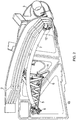
- Figure 1 is a schematic view of the leading edge of an aircraft wing, viewed in cross-section.
- the wing comprises a fixed wing part 1 with a D-nose fixed leading edge skin 2; and a slat 4 movable relative to the fixed wing between a retracted upper position, and an extended lowered position (labelled 4',7').
- the slat 4 is driven between its two positions by a draft shaft 55 and an actuation mechanism which is not shown.
- the actuation mechanism comprises a slat track which extends to the rear of the slat and is driven along a curved path by a set of driven rollers.
- the slat 3 carries a de-icing system (not shown) which heats the leading edge 4 of the slat 3 to prevent the build up of ice.
- a flexible cable (not shown in Figure 1 ) extends between the fixed wing and the slat in order to carry electrical power to the de-icing system.
- a linkage system guides the flexible cable and is adjustable between a retracted position (shown in solid line) when the slat is in its retracted position and an extended position (shown in dashed line) when the slat is in its extended position.
- the linkage comprises a proximal arm 5 which is coupled to the fixed wing by a proximal pivot joint 6; and a distal arm 7 which is coupled to the proximal arm 5 by an intermediate ball-joint 8 and to the slat 3 by a distal pivot joint 9.
- the linkage system 5-9 is passive, in that it does not drive the slat 4 between its two positions, rather it is pulled and pushed by the actuation mechanism (not shown).
- Figures 2-9 are engineering drawings showing various parts of the system of Figure 1 in detail.
- Figure 2 is a sectional view through the leading edge of the wing and shows a leading edge rib 10 to which the proximal pivot joint 6 is attached by a bracket 11.
- the leading edge rib 10 is part of the fixed wing part and extends forwards from a leading-edge spar (not shown).
- Figure 3 is a perspective view of the linkage system
- Figure 4 is a front elevation view
- Figure 5 is a plan view (orthogonal to Figure 4 ).
- the centre line 13 of the distal arm 7 is shown in Figures 4 and 5 .
- the centre line 13 is shaped as a three-dimensional curve: that is, it does not lie in a single plane and appears curved when viewed in all directions (e.g. Figures 4 and 5 ).
- the line 13 forms a smooth curve with little or no straight sections.
- the line 13 is shaped as a three-dimensional curve along a majority of its length, in other words little or none of the curve forms a pure two-dimensional arc lying in a single plane.
- the distal arm 7 is tubular and has an outer periphery which is substantially circular in cross-section.
- the sides of the distal arm 7 also follow the same three-dimensional curve as the centre line 13.
- the distal arm 7 of the linkage passes through an aperture 12 in the leading edge skin 2.
- the three-dimensional curve is designed so that at each position of movement of the slat the centre line 13 of the distal 7 arm passes through approximately the same point of the aperture 12. This enables the aperture in the skin 2 to be small, which provides a number of benefits, including:
- the outer periphery of the distal arm 7 may form a seal with the skin 2, thereby substantially preventing the ingress of foreign objects and air.
- the distal arm may engage a seal member (such as a brush) which is mounted in the aperture.
- the movement of the linkage is statically deterministic: in other words for each position of the slat there is only a single position that the linkage can adopt. This deterministic movement is important to enable the linkage to be consistent and repeatable in its movement.
- the flexible cable 14 is attached to the proximal arm 5 by a series of P-clips 15 and threaded through the interior of the tubular distal arm 7.
- the cable 14 runs loose within the distal arm 7 without any P-clips.
- the interior of the distal arm 7 may be coated in a low friction material such as PTFE to prevent chafing of the cable 14. Bonding leads 50 connect the various parts of the linkage system to prevent the build-up of static electrical charge.
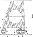
- Figure 6 is a sectional view of the proximal pivot joint 6.
- the pivot joint 6 comprises a pair of clevis joints 6a, 6b with pivot pins 20, 21 which are co-axial and lie parallel with the bracket 11 and the spar (not shown).
- the arm 5 can rotate on the clevis joints 6a, 6b about a single vertical pivot axis.
- the resulting purely horizontal motion of the arm 5 prevents it from interfering with hydraulic or electrical cables (or other system components) running in a spanwise sense along the wing.
- the flexible cable 14 has a helical wound section shown in Figure 6 with a winding axis coincident with the pivot axis.
- a cable protector disc 22,23 is provided at each end of the wound section along the pivot axis so as to constrain the adjacent end of the wound section.
- One of the cable protector discs is keyed with the bracket 11 so it remains stationary as the slat is deployed, and the other cable protector disc is keyed with the arm 5 so it rotates with the arm 5 as the slat is deployed. Further details of the cable protector discs can be found in WO2009130473 .
- Figure 7 is a sectional view of the ball joint 8.
- the proximal arm 5 has a pair of lugs 30,31 which carry a pivot pin 32.
- the distal arm 7 has a lug 35 through which the pivot pin passes.
- the pivot pin has a ball with a spherical bearing surface 33 which engages a complimentary spherical bearing surface 34 of the aperture in the lug 35.
- the ball joint 8 enables the distal arm 7 to rotate relative to the proximal arm 5 about three orthogonal axes including the axis of the pivot pin 32.
- the flexible cable 14 has a helical wound section shown in Figure 7 with a winding axis coincident with the pivot pin 32.
- a cable protector disc 22,23 is provided at each end of the wound section along the pivot axis so as to constrain the adjacent end of the wound section.
- One of the cable protector discs is keyed with the proximal arm 5, and the other cable protector disc is keyed with the distal arm 7 so it rotates with the arm 7 as the slat is deployed. Further details of the cable protector discs can be found in WO2009130473 .
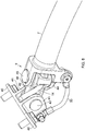
- FIGS. 8-10 show the distal pivot joint 9 in detail.
- the joint comprises a bracket with a pair of wings 40 which are bolted to the slat, and a pair of lugs 41.
- a distal end of a connector 42 is positioned between the lugs 41 and forms a clevis joint with a pivot pin 43.
- the distal arm 7 has a pair of lugs 44.
- a proximal end of the connector 42 is positioned between the lugs 44 and forms a clevis joint with a pivot pin 45 at right angles to the pivot pin 43.
- the distal pivot joint 9 permits the distal arm 7 to rotate relative to the slat about only two orthogonal axes of rotation (that is, the axes of the pivot pins 43 and 45).
- the cable 14 passes out of the distal arm 7 and through a hole in the connector 42.
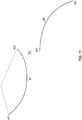
- the three-dimensional curve of the centre-line 13 of the distal arm 7 is designed and manufactured by a process described below and illustrated schematically in Figure 11 .
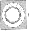
- Figure 12 is a cross-sectional view through the leading edge skin 2 at the point where the distal arm passes through it.
- the skin 2 has an aperture 53 through which the arm 7 passes.
- Figure 12 is highly schematic. For instance the cable passing through the distal arm is not shown for purposes of clarity. Also the shape of the aperture 53 is shown as a symmetrical shape when in fact it may have a more complex shape.
- the distal arm 7 cross-section is shown in solid lines and is centred on the central point X of the aperture.
- the distal arm 7 is shown at another position in its movement in dashed lines. In this position the cross-section has become oval (since the arm 7 is not passing through the skin at right angles). Also it has moved slightly towards the edge of the aperture.
- the degree of movement is relatively small so that at each position of movement of the slat a part of the distal arm cross-section coincides with the central point X of the aperture 53.
Landscapes
- Engineering & Computer Science (AREA)
- General Engineering & Computer Science (AREA)
- Mechanical Engineering (AREA)
- Aviation & Aerospace Engineering (AREA)
- Mechanical Control Devices (AREA)
- Automation & Control Theory (AREA)
- Manipulator (AREA)
- Blinds (AREA)
- Flexible Shafts (AREA)
- Toys (AREA)
- Pivots And Pivotal Connections (AREA)
Description
- The present invention relates to a linkage for guiding and protecting a flexible cable between first and second structures, the second structure being movable relative to the first structure. The linkage comprises a proximal arm with a proximal pivot joint for coupling the proximal arm to a first one of the two structures; and a distal arm which is coupled to the proximal arm by one or more intermediate pivot joints.
-
US 2006/0038088 discloses an aircraft wing comprising a fixed wing and a slat movable relative to the fixed wing between a retracted position and an extended position. An electrical cable extends between the fixed wing and an electrical system on the slat, and a linkage guides the electrical cable between the two structures. The linkage is adjustable between a retracted position when the slat is in its retracted position and an extended position when the slat is in its extended position. The linkage comprises three links which are connected together by two pivot joints. The linkage is coupled to the fixed wing by a rotary joint and to the slat by a gimbal joint. The links have generally straight profiles, although curved or angled links can be used if necessary and/or appropriate. - As the linkage extends, it rotates down about the rotary joint. As a result a large aperture must be provided in the leading edge skin of the fixed wing to accommodate the movement of the linkage. Such a large aperture results in a number of problems. Firstly, the aperture will admit air into the interior of the leading edge and thus create undesirable aerodynamic effects. Secondly, the aperture will admit foreign objects into the interior of the leading edge which may damage structure such as the spar, hydraulic cables or electrical cables. Thirdly the aperture will weaken the leading edge skin of the fixed wing. This is a particular problem if the skin is formed from composite material.
- A further problem with the downward rotation of the linkage about the rotary joint is that the linkage will tend to interfere with hydraulic or electrical cables (or other system components) running in a spanwise sense along the wing.
- A first aspect of the invention provides a cable guiding linkage for guiding and protecting a flexible cable between first and second structures, the second structure being movable relative to the first structure. The linkage comprises a proximal arm; a proximal pivot joint for coupling the proximal arm to the first structure; and a distal arm which is coupled to the proximal arm by one or more intermediate pivot joints. The distal arm is shaped as a three-dimensional curve along a majority of its length, wherein the three-dimensional curve does not lie in a single plane and appears curved when viewed in all directions. Shaping the distal arm as a three-dimensional curve along a majority of its length enables the distal arm to pass through a relatively small aperture as the linkage is adjusted between its retracted and extended positions. It also enables the proximal arm to occupy a swept volume as it moves which does not interfere with other system components.
- The linkage can be used to guide and protect a flexible cable between any two structures. For instance the cable may provide electrical power to a wing-ice protection system on an aircraft slat, to a leading edge failure detection device on an aircraft slat, or to a device on a trailing edge aircraft flap. Alternatively the cable may be part of a harness on an aircraft landing gear. Alternatively the cable may provide electrical power to a component on a door.
- The cable may be an electrical cable, a hydraulic or pneumatic cable for carrying hydraulic or pneumatic fluid, or any other flexible line.
- Typically the proximal pivot joint only permits the proximal arm to rotate relative to the first one of the structures about a single axis of rotation.
- Preferably the intermediate pivot joint (or joints) permit the distal arm to rotate relative to the proximal arm about two or more axes of rotation. For instance the intermediate pivot joint may comprise a series of single-axis pivot joints, or a ball joint. Preferably the intermediate pivot joint (or joints) permit the distal arm to rotate relative to the proximal arm about three more axes of rotation, and most preferably it comprises a ball joint which permits the distal arm to rotate relative to the proximal arm about three axes of rotation.
- Typically the linkage further comprises a distal pivot joint for coupling the distal arm to a second one of the two structures. Preferably the distal pivot joint permits the distal arm to rotate relative to the second one of the structures about at least two axes of rotation. The distal pivot joint may comprise a pair of single-axis joints which are connected together by a connector. Preferably the distal pivot joint permits the distal arm to rotate relative to the second one of the structures about no more than two axes of rotation since this enables the movement of the linkage to be statically deterministic.
- Typically the distal arm is tubular. The tubular shape enables the flexible cable to be guided within the interior of the tube and protects the flexible cable from electromagnetic interference.
- Typically the distal arm has a centre line which is shaped as a three-dimensional curve along a majority of its length.
- Typically the linkage further comprises a helical channel for guiding the flexible cable in one or more coils. Preferably the axis of the helical channel is substantially coaxial with the pivot joint which couples the proximal arm to the distal arm.
- Typically the distal arm has an outer periphery which is substantially circular or oval in cross-section. A circular or oval cross-section is preferred because it provides a smooth surface to seal against other structure. It also provides a low drag aerodynamic profile.
- A second aspect of the invention provides an aircraft wing comprising: a fixed wing having a skin; a control surface movable relative to the fixed wing between a retracted position and an extended position; a flexible cable extending between the fixed wing and the control surface; and a linkage according to the first aspect of the invention guiding and protecting the flexible cable and movable between a retracted position when the control surface is in its retracted position and an extended position when the control surface is in its extended position, wherein the linkage comprises a proximal arm which is coupled to the fixed wing by a proximal pivot joint; and a distal arm which is coupled to the proximal arm by one or more intermediate pivot joints and to the control surface by a distal pivot joint, wherein the distal arm of the linkage passes through an aperture in the skin of the fixed wing and is shaped as a three-dimensional curve.
- The control surface may be a slat on the leading edge of the wing, a flap on the trailed edge of the wing, or any other movable control surface.
- The distal arm may engage the skin of the fixed wing as it passes through the aperture, typically via a flexible resilient sealing member such as a brush or rubber seal.
- A further aspect of the invention provides a method of deploying the control surface of the aircraft wing of the second aspect of the invention, the method comprising: moving the control surface relative to the fixed wing between a retracted position and an extended position; and moving the linkage between a retracted position when the control surface is in its retracted position and an extended position when the slat is in its extended position, wherein at each position of movement of the control surface a part of the distal arm cross-section passes through the same point of the aperture.
- Embodiments of the invention will now be described with reference to the accompanying drawings, in which:
-
Figure 1 is a schematic view of the leading edge of an aircraft wing, viewed in cross-section; -
Figure 2 is a sectional view through the leading edge of a wing; -
Figure 3 is a perspective view of the linkage mechanism; -
Figure 4 is a front elevation view of the linkage mechanism; -
Figure 5 is a plan view of the linkage mechanism; -
Figure 6 is a sectional view of the proximal pivot joint; -
Figure 7 is a sectional view of the intermediate ball joint; -
Figure 8 is a perspective view of the distal pivot joint; -
Figure 9 is a side view of the distal pivot joint; -
Figure 10 is a sectional view of the distal pivot joint; -
Figure 11 is a schematic drawing showing how the three-dimensional curve of the centre-line of the distal arm is calculated; and -
Figure 12 is a schematic cross-sectional view through the skin and distal arm. -
Figure 1 is a schematic view of the leading edge of an aircraft wing, viewed in cross-section. The wing comprises a fixedwing part 1 with a D-nose fixed leadingedge skin 2; and aslat 4 movable relative to the fixed wing between a retracted upper position, and an extended lowered position (labelled 4',7'). Theslat 4 is driven between its two positions by adraft shaft 55 and an actuation mechanism which is not shown. Typically the actuation mechanism comprises a slat track which extends to the rear of the slat and is driven along a curved path by a set of driven rollers. - The
slat 3 carries a de-icing system (not shown) which heats theleading edge 4 of theslat 3 to prevent the build up of ice. A flexible cable (not shown inFigure 1 ) extends between the fixed wing and the slat in order to carry electrical power to the de-icing system. - A linkage system guides the flexible cable and is adjustable between a retracted position (shown in solid line) when the slat is in its retracted position and an extended position (shown in dashed line) when the slat is in its extended position. The linkage comprises a
proximal arm 5 which is coupled to the fixed wing by a proximal pivot joint 6; and adistal arm 7 which is coupled to theproximal arm 5 by an intermediate ball-joint 8 and to theslat 3 by adistal pivot joint 9. The linkage system 5-9 is passive, in that it does not drive theslat 4 between its two positions, rather it is pulled and pushed by the actuation mechanism (not shown). -
Figures 2-9 are engineering drawings showing various parts of the system ofFigure 1 in detail.Figure 2 is a sectional view through the leading edge of the wing and shows aleading edge rib 10 to which theproximal pivot joint 6 is attached by abracket 11. Theleading edge rib 10 is part of the fixed wing part and extends forwards from a leading-edge spar (not shown). -
Figure 3 is a perspective view of the linkage system,Figure 4 is a front elevation view andFigure 5 is a plan view (orthogonal toFigure 4 ). Thecentre line 13 of thedistal arm 7 is shown inFigures 4 and 5 . In order to pass through the skin of the leading edge at a single point, thecentre line 13 is shaped as a three-dimensional curve: that is, it does not lie in a single plane and appears curved when viewed in all directions (e.g.Figures 4 and 5 ). Note also that theline 13 forms a smooth curve with little or no straight sections. Also, theline 13 is shaped as a three-dimensional curve along a majority of its length, in other words little or none of the curve forms a pure two-dimensional arc lying in a single plane. - The
distal arm 7 is tubular and has an outer periphery which is substantially circular in cross-section. Thus the sides of thedistal arm 7 also follow the same three-dimensional curve as thecentre line 13. As can be seen inFigure 2 , thedistal arm 7 of the linkage passes through anaperture 12 in theleading edge skin 2. The three-dimensional curve is designed so that at each position of movement of the slat thecentre line 13 of the distal 7 arm passes through approximately the same point of theaperture 12. This enables the aperture in theskin 2 to be small, which provides a number of benefits, including: - increasing the strength of the
skin 2, which will make it more resistant to birdstrike impact - minimising the ingress of foreign objects
- minimising the ingress of air, thus improving the aerodynamic performance of the wing.
- Optionally the outer periphery of the
distal arm 7 may form a seal with theskin 2, thereby substantially preventing the ingress of foreign objects and air. For instance the distal arm may engage a seal member (such as a brush) which is mounted in the aperture. - The movement of the linkage is statically deterministic: in other words for each position of the slat there is only a single position that the linkage can adopt. This deterministic movement is important to enable the linkage to be consistent and repeatable in its movement.
- Returning to
Figure 3 , theflexible cable 14 is attached to theproximal arm 5 by a series of P-clips 15 and threaded through the interior of the tubulardistal arm 7. Thecable 14 runs loose within thedistal arm 7 without any P-clips. The interior of thedistal arm 7 may be coated in a low friction material such as PTFE to prevent chafing of thecable 14. Bonding leads 50 connect the various parts of the linkage system to prevent the build-up of static electrical charge. -
Figure 6 is a sectional view of theproximal pivot joint 6. Thepivot joint 6 comprises a pair ofclevis joints 6a, 6b with pivot pins 20, 21 which are co-axial and lie parallel with thebracket 11 and the spar (not shown). Thus thearm 5 can rotate on theclevis joints 6a, 6b about a single vertical pivot axis. The resulting purely horizontal motion of thearm 5 prevents it from interfering with hydraulic or electrical cables (or other system components) running in a spanwise sense along the wing. - The
flexible cable 14 has a helical wound section shown inFigure 6 with a winding axis coincident with the pivot axis. Acable protector disc bracket 11 so it remains stationary as the slat is deployed, and the other cable protector disc is keyed with thearm 5 so it rotates with thearm 5 as the slat is deployed. Further details of the cable protector discs can be found inWO2009130473 .Figure 7 is a sectional view of the ball joint 8. Theproximal arm 5 has a pair oflugs pivot pin 32. Thedistal arm 7 has alug 35 through which the pivot pin passes. The pivot pin has a ball with aspherical bearing surface 33 which engages a complimentaryspherical bearing surface 34 of the aperture in thelug 35. Thus the ball joint 8 enables thedistal arm 7 to rotate relative to theproximal arm 5 about three orthogonal axes including the axis of thepivot pin 32. - The
flexible cable 14 has a helical wound section shown inFigure 7 with a winding axis coincident with thepivot pin 32. Acable protector disc proximal arm 5, and the other cable protector disc is keyed with thedistal arm 7 so it rotates with thearm 7 as the slat is deployed. Further details of the cable protector discs can be found inWO2009130473 . -
Figures 8-10 show the distal pivot joint 9 in detail. The joint comprises a bracket with a pair ofwings 40 which are bolted to the slat, and a pair oflugs 41. A distal end of aconnector 42 is positioned between thelugs 41 and forms a clevis joint with apivot pin 43. Thedistal arm 7 has a pair oflugs 44. A proximal end of theconnector 42 is positioned between thelugs 44 and forms a clevis joint with apivot pin 45 at right angles to thepivot pin 43. Thus the distal pivot joint 9 permits thedistal arm 7 to rotate relative to the slat about only two orthogonal axes of rotation (that is, the axes of the pivot pins 43 and 45). - The
cable 14 passes out of thedistal arm 7 and through a hole in theconnector 42. The three-dimensional curve of the centre-line 13 of thedistal arm 7 is designed and manufactured by a process described below and illustrated schematically inFigure 11 . - 1. An arc of
movement 51 of the centre of the ball-joint 8 at the end of the proximal arm is plotted as a first curve with end points a(1) and a(2). Since theproximal arm 5 is mounted on a single-axis pivot joint 6, this arc ofmovement 51 is a two-dimensional curve with a constant curvature. - 2. An arc of
movement 52 of the distal end of thearm 7 is plotted as a second series curve with end points b(1) and b(2). This curve may be a two or three-dimensional curve but must have the same length as thecurve 51. - 3. At each point of movement, the ends of the
distal arm 7 must be at points a(1), b(1) etc., and thecentre line 13 must also pass through (or close to) a point X at the centre of the aperture in the skin. This enables the shape of the three-dimensional centre line 13 to be calculated. - 4. The
distal arm 7 is manufactured with acentre line 13 which is shaped to form the three-dimensional curve. The tube may be formed by deforming an initially straight tube in a press, or by passing an initially straight tube through a 3D CNC pipe bending machine which bends the tube as it is passed through the machine. -
Figure 12 is a cross-sectional view through theleading edge skin 2 at the point where the distal arm passes through it. Theskin 2 has anaperture 53 through which thearm 7 passes. Note thatFigure 12 is highly schematic. For instance the cable passing through the distal arm is not shown for purposes of clarity. Also the shape of theaperture 53 is shown as a symmetrical shape when in fact it may have a more complex shape. - At the start of its movement the
distal arm 7 cross-section is shown in solid lines and is centred on the central point X of the aperture. As the slat deploys there will be a small amount of relative movement between the distal arm cross-section and the aperture. For instance thedistal arm 7 is shown at another position in its movement in dashed lines. In this position the cross-section has become oval (since thearm 7 is not passing through the skin at right angles). Also it has moved slightly towards the edge of the aperture. However, the degree of movement is relatively small so that at each position of movement of the slat a part of the distal arm cross-section coincides with the central point X of theaperture 53. - The use of a three-axis ball joint (instead of a series of three single axis joints) is preferred because it enables a relatively small amount of movement between the
centre line 13 and the central point X of the aperture. - Although the invention has been described above with reference to one or more preferred embodiments, it will be appreciated that various changes or modifications may be made without departing from the scope of the invention as defined in the appended claims.
Claims (15)
- A cable guiding linkage for guiding and protecting a flexible cable between first and second structures (1,3,4), the second structure (3,4) being movable relative to the first structure, the linkage comprising a proximal arm (5); a proximal pivot joint (6) for coupling the proximal arm to the first structure; and a distal arm (7) which is coupled to the proximal arm by one or more intermediate pivot joints (8), characterised in that the distal arm (7) is shaped as a three-dimensional curve along a majority of its length, wherein the three-dimensional curve does not lie in a single plane and appears curved when viewed in all directions.
- The cable guiding linkage of claim 1 wherein the intermediate pivot joint(s) (8) permit the distal arm (7) to rotate relative to the proximal arm (5) about two or more axes of rotation.
- The cable guiding linkage of claim 2 wherein the distal arm (7) is coupled to the proximal arm (5) by a ball joint (8).
- The cable guiding linkage of claim 3 wherein the ball joint (8) permits the distal arm (7) to rotate relative to the proximal arm (5) about three axes of rotation.
- The cable guiding linkage of any preceding claim further comprising a distal pivot joint (9) for coupling the distal arm (7) to the second structure (3).
- The cable guiding linkage of claim 5, wherein the distal pivot joint (9) permits the distal arm (7) to rotate relative to the second structure (3) about at least two axes of rotation.
- The cable guiding linkage of claim 6 wherein the distal pivot joint (9) comprises a pair of single-axis joints which are connected together by a connector (42).
- The cable guiding linkage of any preceding claim wherein the distal arm (7) is tubular.
- The cable guiding linkage of any preceding claim wherein the distal arm (7) has a centre line (13) which is shaped as a three-dimensional curve along a majority of its length.
- The cable guiding linkage of any preceding claim further comprising a helical channel for guiding the flexible cable (14) in one or more coils.
- The cable guiding linkage of claim 10 wherein the axis of the helical channel is substantially coaxial with the intermediate pivot joint (8) which couples the proximal arm (5) to the distal arm (7).
- An aircraft wing comprising: a fixed wing (1) having a skin (2); a control surface (3) movable relative to the fixed wing between a retracted position (4) and an extended position (4'); a flexible cable (14) extending between the fixed wing and the control surface; and a cable guiding linkage according to any preceding claim guiding the flexible cable (14) and movable between a retracted position (4) when the control surface is in its retracted position and an extended position (4') when the control surface is in its extended position, wherein the linkage comprises a proximal arm (5) which is coupled to the fixed wing (1) by a proximal pivot joint (6); and a distal arm (7) which is coupled to the proximal arm (5) by one or more intermediate pivot joints (8) and to the control surface by a distal pivot joint, wherein the distal arm (7) of the linkage passes through an aperture (53) in the skin of the fixed wing (1) and is shaped as a three-dimensional curve.
- The aircraft wing of claim 12 wherein the distal arm (7) engages the skin (2) of the fixed wing (1) as it passes through the aperture (53).
- The aircraft wing of claim 12 or 13 wherein the control surface (34) is a leading edge slat.
- A method of deploying the control surface (3) of the aircraft wing of claim 12, 13 or 14, the method comprising:moving the control surface (3) relative to the fixed wing (1) between a retracted position (4) and an extended position (4'); and moving the cable guiding linkage between a retracted position when the control surface (3) is in its retracted position (4) and an extended position when the control surface (3) is in its extended position (4'), wherein at each position of movement of the control surface (3) a part of the distal arm cross-section passes through the same point of the aperture (53).
Applications Claiming Priority (2)
| Application Number | Priority Date | Filing Date | Title |
|---|---|---|---|
| GBGB1011378.5A GB201011378D0 (en) | 2010-07-06 | 2010-07-06 | Linkage for guiding a flexible cable |
| PCT/GB2011/051265 WO2012004594A1 (en) | 2010-07-06 | 2011-07-05 | Linkage for guiding a flexible cable |
Publications (2)
| Publication Number | Publication Date |
|---|---|
| EP2590857A1 EP2590857A1 (en) | 2013-05-15 |
| EP2590857B1 true EP2590857B1 (en) | 2017-08-23 |
Family
ID=42669269
Family Applications (1)
| Application Number | Title | Priority Date | Filing Date |
|---|---|---|---|
| EP11732504.3A Active EP2590857B1 (en) | 2010-07-06 | 2011-07-05 | Linkage for guiding a flexible cable |
Country Status (8)
| Country | Link |
|---|---|
| US (1) | US9187171B2 (en) |
| EP (1) | EP2590857B1 (en) |
| JP (1) | JP5829683B2 (en) |
| BR (1) | BR112013000412B1 (en) |
| CA (1) | CA2802914C (en) |
| ES (1) | ES2640444T3 (en) |
| GB (1) | GB201011378D0 (en) |
| WO (1) | WO2012004594A1 (en) |
Cited By (2)
| Publication number | Priority date | Publication date | Assignee | Title |
|---|---|---|---|---|
| US11440665B2 (en) | 2018-10-23 | 2022-09-13 | Airbus Operations Gmbh | Vented leading-edge assembly and method for manufacturing a vented leading-edge assembly |
| EP4686649A1 (en) * | 2024-07-29 | 2026-02-04 | Airbus Operations Limited | Wing assembly |
Families Citing this family (14)
| Publication number | Priority date | Publication date | Assignee | Title |
|---|---|---|---|---|
| DE102011018906A1 (en) * | 2011-04-28 | 2012-10-31 | Airbus Operations Gmbh | High lift system for an aircraft and method for influencing the high lift characteristics of an aircraft |
| GB201121447D0 (en) * | 2011-12-14 | 2012-01-25 | Airbus Operations Ltd | Translating cable device sealing |
| GB201209686D0 (en) * | 2012-05-31 | 2012-07-18 | Airbus Operations Ltd | A slat support assembly |
| FR2998260B1 (en) * | 2012-11-16 | 2015-02-13 | Dassault Aviat | MOBILE CABLE GUIDING DEVICE, AND AIRCRAFT COMPRISING SUCH A DEVICE |
| US9284047B2 (en) * | 2013-08-02 | 2016-03-15 | Goodrich Corporation | Routings for articulated landing gear |
| US10899430B2 (en) * | 2015-02-05 | 2021-01-26 | Airbus Canada Limited Partnership | Apparatus for obstructing air flow through an aperture for a duct in an aircraft wing |
| US11192625B2 (en) * | 2016-06-17 | 2021-12-07 | Bombardier Inc. | Panels for obstructing air flow through apertures in an aircraft wing |
| NL2017880B1 (en) * | 2016-11-28 | 2018-06-08 | Fokker Elmo B V | Guidance element with internal conduit between two constructional parts |
| US11148821B2 (en) * | 2019-02-28 | 2021-10-19 | Hamilton Sundstrand Corporation | Motion limiter for ram air turbine (RAT) door linkage |
| GB2582149A (en) | 2019-03-12 | 2020-09-16 | Airbus Operations Ltd | Slat for an aircraft wing |
| CN110641682A (en) * | 2019-11-26 | 2020-01-03 | 中国商用飞机有限责任公司 | Rocker arm type motion cable mechanism |
| GB2593446A (en) * | 2020-03-11 | 2021-09-29 | Airbus Operations Ltd | Aircraft systems and electrical connectors |
| CN113555836B (en) * | 2021-07-05 | 2023-03-03 | 陕西宝成航空仪表有限责任公司 | Telescopic cable device for aircraft wire interconnection system |
| EP4733189A1 (en) * | 2024-10-22 | 2026-04-29 | Airbus Operations Limited | A wing assembly comprising a wiring harness |
Citations (2)
| Publication number | Priority date | Publication date | Assignee | Title |
|---|---|---|---|---|
| JPH0419207A (en) * | 1990-05-15 | 1992-01-23 | Toyota Motor Corp | Suspension for vehicle |
| DE102008027178A1 (en) * | 2008-06-06 | 2009-01-15 | Daimler Ag | Vehicle suspension for steering wheels on front axle, includes bearing assemblies with redundancy and diversity, containing needle roller bearing and dry-lubricated sleeve bearing |
Family Cites Families (15)
| Publication number | Priority date | Publication date | Assignee | Title |
|---|---|---|---|---|
| US522009A (en) | 1894-06-26 | Device for increasing draft in smoke-stacks | ||
| US2246116A (en) * | 1937-10-28 | 1941-06-17 | Messerschmitt Boelkow Blohm | Airplane wing structure |
| US2218114A (en) * | 1938-04-04 | 1940-10-15 | Messerschmitt Boelkow Blohm | Operating mechanism for aircraft wing flaps |
| US2973925A (en) | 1958-03-24 | 1961-03-07 | Lockheed Aircraft Corp | Aerodynamically automatic airfoil slat mechanism |
| DE2916040C2 (en) * | 1979-04-20 | 1986-01-02 | Messerschmitt-Bölkow-Blohm GmbH, 8012 Ottobrunn | Wing for an aircraft with movable slats |
| DE3013774A1 (en) * | 1980-04-10 | 1981-10-15 | Vereinigte Flugtechnische Werke Gmbh, 2800 Bremen | OPERATING ARRANGEMENT FOR FLAP VALVES |
| FR2547270B1 (en) * | 1983-06-10 | 1985-09-06 | Boeing Co | EXTENSION AND RETRACTION MECHANISM FOR AN ATTACK SHUTTER OF AN AIRCRAFT WING |
| JPH04156217A (en) * | 1990-10-18 | 1992-05-28 | Fujitsu Ltd | Cable guide device |
| US6010097A (en) * | 1997-10-16 | 2000-01-04 | Northrop Grumman Corporation | Scissor linkage type slotted flap mechanism |
| GB2390800B (en) * | 2002-07-16 | 2005-10-26 | Colebrook Bosson Saunders Prod | Support for electrical display device |
| US7249375B2 (en) | 2003-08-05 | 2007-07-24 | Oracle International Corp | Method and apparatus for end-to-end identity propagation |
| CA2515276A1 (en) * | 2004-08-23 | 2006-02-23 | Goodrich Corporation | Aircraft wing |
| US7264212B2 (en) * | 2005-05-20 | 2007-09-04 | Chin-Jui Hung | Monitor-holding device |
| US7249735B2 (en) * | 2005-06-30 | 2007-07-31 | The Boeing Company | Translating conduit apparatus for an airplane or equipment |
| GB0807626D0 (en) | 2008-04-25 | 2008-06-04 | Ultra Electronics Ltd | Routing of cables |
-
2010
- 2010-07-06 GB GBGB1011378.5A patent/GB201011378D0/en not_active Ceased
-
2011
- 2011-07-05 BR BR112013000412-6A patent/BR112013000412B1/en active IP Right Grant
- 2011-07-05 WO PCT/GB2011/051265 patent/WO2012004594A1/en not_active Ceased
- 2011-07-05 US US13/808,368 patent/US9187171B2/en active Active
- 2011-07-05 CA CA2802914A patent/CA2802914C/en active Active
- 2011-07-05 EP EP11732504.3A patent/EP2590857B1/en active Active
- 2011-07-05 ES ES11732504.3T patent/ES2640444T3/en active Active
- 2011-07-05 JP JP2013517546A patent/JP5829683B2/en active Active
Patent Citations (2)
| Publication number | Priority date | Publication date | Assignee | Title |
|---|---|---|---|---|
| JPH0419207A (en) * | 1990-05-15 | 1992-01-23 | Toyota Motor Corp | Suspension for vehicle |
| DE102008027178A1 (en) * | 2008-06-06 | 2009-01-15 | Daimler Ag | Vehicle suspension for steering wheels on front axle, includes bearing assemblies with redundancy and diversity, containing needle roller bearing and dry-lubricated sleeve bearing |
Cited By (2)
| Publication number | Priority date | Publication date | Assignee | Title |
|---|---|---|---|---|
| US11440665B2 (en) | 2018-10-23 | 2022-09-13 | Airbus Operations Gmbh | Vented leading-edge assembly and method for manufacturing a vented leading-edge assembly |
| EP4686649A1 (en) * | 2024-07-29 | 2026-02-04 | Airbus Operations Limited | Wing assembly |
Also Published As
| Publication number | Publication date |
|---|---|
| US9187171B2 (en) | 2015-11-17 |
| JP2013529578A (en) | 2013-07-22 |
| US20130233967A1 (en) | 2013-09-12 |
| CA2802914C (en) | 2018-07-31 |
| ES2640444T3 (en) | 2017-11-03 |
| BR112013000412A8 (en) | 2017-10-17 |
| JP5829683B2 (en) | 2015-12-09 |
| CA2802914A1 (en) | 2012-01-12 |
| BR112013000412B1 (en) | 2021-01-26 |
| EP2590857A1 (en) | 2013-05-15 |
| WO2012004594A1 (en) | 2012-01-12 |
| BR112013000412A2 (en) | 2016-05-17 |
| GB201011378D0 (en) | 2010-08-18 |
Similar Documents
| Publication | Publication Date | Title |
|---|---|---|
| US9187171B2 (en) | Linkage for guiding a flexible cable | |
| US7249735B2 (en) | Translating conduit apparatus for an airplane or equipment | |
| US20060038088A1 (en) | Aircraft wing | |
| RU2752205C2 (en) | Aircraft wing console | |
| CN104176239A (en) | Flap arrangement for a wing of an aircraft and an aircraft with a wing comprising such a flap arrangement | |
| MX2009000552A (en) | Retractable rotor blade structure. | |
| EP3310651B1 (en) | Aircraft wing system | |
| EP4063257B1 (en) | Wing for an aircraft | |
| US20180162516A1 (en) | Aircraft wing system | |
| EP3395679B1 (en) | Wing for an aircraft | |
| EP4093669B1 (en) | Aircraft systems and electrical connectors | |
| EP2886451A1 (en) | Trailing-edge flap system for a wing of an aircraft and aircraft comprising a wing and at least one such trailing-edge flap system | |
| US20170275016A1 (en) | Apparatus to store a drogue hose on an aircraft | |
| CN107878732B (en) | System for driving and guiding trailing edge control surfaces | |
| CN108216578A (en) | the wing of aircraft | |
| EP4114644B1 (en) | Apparatus and method for depositing an elongate fiber tow | |
| US10625875B2 (en) | Apparatus to store a drogue hose on an aircraft | |
| EP4450260A1 (en) | Apparatus and method for applying an elongate fiber tow | |
| KR20230085460A (en) | Morphing wing device | |
| CN218586865U (en) | Telescopic cable device, wing with the telescopic cable device and aircraft | |
| EP3106385A1 (en) | Aircraft wing system | |
| US12612152B2 (en) | Wing for an aircraft | |
| ZA201000868B (en) | Aircraft control surfaces and mechanisms for moving same |
Legal Events
| Date | Code | Title | Description |
|---|---|---|---|
| PUAI | Public reference made under article 153(3) epc to a published international application that has entered the european phase |
Free format text: ORIGINAL CODE: 0009012 |
|
| 17P | Request for examination filed |
Effective date: 20130205 |
|
| AK | Designated contracting states |
Kind code of ref document: A1 Designated state(s): AL AT BE BG CH CY CZ DE DK EE ES FI FR GB GR HR HU IE IS IT LI LT LU LV MC MK MT NL NO PL PT RO RS SE SI SK SM TR |
|
| DAX | Request for extension of the european patent (deleted) | ||
| REG | Reference to a national code |
Ref country code: DE Ref legal event code: R079 Ref document number: 602011040852 Country of ref document: DE Free format text: PREVIOUS MAIN CLASS: B64C0009140000 Ipc: B64C0009220000 |
|
| RIC1 | Information provided on ipc code assigned before grant |
Ipc: B64C 9/22 20060101AFI20160712BHEP Ipc: F16C 7/02 20060101ALI20160712BHEP Ipc: B64C 13/30 20060101ALI20160712BHEP |
|
| 17Q | First examination report despatched |
Effective date: 20160905 |
|
| GRAP | Despatch of communication of intention to grant a patent |
Free format text: ORIGINAL CODE: EPIDOSNIGR1 |
|
| STAA | Information on the status of an ep patent application or granted ep patent |
Free format text: STATUS: GRANT OF PATENT IS INTENDED |
|
| INTG | Intention to grant announced |
Effective date: 20170302 |
|
| GRAS | Grant fee paid |
Free format text: ORIGINAL CODE: EPIDOSNIGR3 |
|
| GRAA | (expected) grant |
Free format text: ORIGINAL CODE: 0009210 |
|
| STAA | Information on the status of an ep patent application or granted ep patent |
Free format text: STATUS: THE PATENT HAS BEEN GRANTED |
|
| AK | Designated contracting states |
Kind code of ref document: B1 Designated state(s): AL AT BE BG CH CY CZ DE DK EE ES FI FR GB GR HR HU IE IS IT LI LT LU LV MC MK MT NL NO PL PT RO RS SE SI SK SM TR |
|
| REG | Reference to a national code |
Ref country code: GB Ref legal event code: FG4D |
|
| REG | Reference to a national code |
Ref country code: CH Ref legal event code: EP |
|
| REG | Reference to a national code |
Ref country code: AT Ref legal event code: REF Ref document number: 921026 Country of ref document: AT Kind code of ref document: T Effective date: 20170915 |
|
| REG | Reference to a national code |
Ref country code: IE Ref legal event code: FG4D |
|
| REG | Reference to a national code |
Ref country code: DE Ref legal event code: R096 Ref document number: 602011040852 Country of ref document: DE |
|
| REG | Reference to a national code |
Ref country code: ES Ref legal event code: FG2A Ref document number: 2640444 Country of ref document: ES Kind code of ref document: T3 Effective date: 20171103 |
|
| REG | Reference to a national code |
Ref country code: NL Ref legal event code: MP Effective date: 20170823 |
|
| REG | Reference to a national code |
Ref country code: LT Ref legal event code: MG4D |
|
| REG | Reference to a national code |
Ref country code: AT Ref legal event code: MK05 Ref document number: 921026 Country of ref document: AT Kind code of ref document: T Effective date: 20170823 |
|
| PG25 | Lapsed in a contracting state [announced via postgrant information from national office to epo] |
Ref country code: FI Free format text: LAPSE BECAUSE OF FAILURE TO SUBMIT A TRANSLATION OF THE DESCRIPTION OR TO PAY THE FEE WITHIN THE PRESCRIBED TIME-LIMIT Effective date: 20170823 Ref country code: HR Free format text: LAPSE BECAUSE OF FAILURE TO SUBMIT A TRANSLATION OF THE DESCRIPTION OR TO PAY THE FEE WITHIN THE PRESCRIBED TIME-LIMIT Effective date: 20170823 Ref country code: LT Free format text: LAPSE BECAUSE OF FAILURE TO SUBMIT A TRANSLATION OF THE DESCRIPTION OR TO PAY THE FEE WITHIN THE PRESCRIBED TIME-LIMIT Effective date: 20170823 Ref country code: AT Free format text: LAPSE BECAUSE OF FAILURE TO SUBMIT A TRANSLATION OF THE DESCRIPTION OR TO PAY THE FEE WITHIN THE PRESCRIBED TIME-LIMIT Effective date: 20170823 Ref country code: NO Free format text: LAPSE BECAUSE OF FAILURE TO SUBMIT A TRANSLATION OF THE DESCRIPTION OR TO PAY THE FEE WITHIN THE PRESCRIBED TIME-LIMIT Effective date: 20171123 Ref country code: SE Free format text: LAPSE BECAUSE OF FAILURE TO SUBMIT A TRANSLATION OF THE DESCRIPTION OR TO PAY THE FEE WITHIN THE PRESCRIBED TIME-LIMIT Effective date: 20170823 Ref country code: NL Free format text: LAPSE BECAUSE OF FAILURE TO SUBMIT A TRANSLATION OF THE DESCRIPTION OR TO PAY THE FEE WITHIN THE PRESCRIBED TIME-LIMIT Effective date: 20170823 |
|
| PG25 | Lapsed in a contracting state [announced via postgrant information from national office to epo] |
Ref country code: GR Free format text: LAPSE BECAUSE OF FAILURE TO SUBMIT A TRANSLATION OF THE DESCRIPTION OR TO PAY THE FEE WITHIN THE PRESCRIBED TIME-LIMIT Effective date: 20171124 Ref country code: RS Free format text: LAPSE BECAUSE OF FAILURE TO SUBMIT A TRANSLATION OF THE DESCRIPTION OR TO PAY THE FEE WITHIN THE PRESCRIBED TIME-LIMIT Effective date: 20170823 Ref country code: LV Free format text: LAPSE BECAUSE OF FAILURE TO SUBMIT A TRANSLATION OF THE DESCRIPTION OR TO PAY THE FEE WITHIN THE PRESCRIBED TIME-LIMIT Effective date: 20170823 Ref country code: BG Free format text: LAPSE BECAUSE OF FAILURE TO SUBMIT A TRANSLATION OF THE DESCRIPTION OR TO PAY THE FEE WITHIN THE PRESCRIBED TIME-LIMIT Effective date: 20171123 Ref country code: PL Free format text: LAPSE BECAUSE OF FAILURE TO SUBMIT A TRANSLATION OF THE DESCRIPTION OR TO PAY THE FEE WITHIN THE PRESCRIBED TIME-LIMIT Effective date: 20170823 Ref country code: IS Free format text: LAPSE BECAUSE OF FAILURE TO SUBMIT A TRANSLATION OF THE DESCRIPTION OR TO PAY THE FEE WITHIN THE PRESCRIBED TIME-LIMIT Effective date: 20171223 |
|
| PG25 | Lapsed in a contracting state [announced via postgrant information from national office to epo] |
Ref country code: CZ Free format text: LAPSE BECAUSE OF FAILURE TO SUBMIT A TRANSLATION OF THE DESCRIPTION OR TO PAY THE FEE WITHIN THE PRESCRIBED TIME-LIMIT Effective date: 20170823 Ref country code: DK Free format text: LAPSE BECAUSE OF FAILURE TO SUBMIT A TRANSLATION OF THE DESCRIPTION OR TO PAY THE FEE WITHIN THE PRESCRIBED TIME-LIMIT Effective date: 20170823 Ref country code: RO Free format text: LAPSE BECAUSE OF FAILURE TO SUBMIT A TRANSLATION OF THE DESCRIPTION OR TO PAY THE FEE WITHIN THE PRESCRIBED TIME-LIMIT Effective date: 20170823 |
|
| REG | Reference to a national code |
Ref country code: DE Ref legal event code: R097 Ref document number: 602011040852 Country of ref document: DE |
|
| PG25 | Lapsed in a contracting state [announced via postgrant information from national office to epo] |
Ref country code: SK Free format text: LAPSE BECAUSE OF FAILURE TO SUBMIT A TRANSLATION OF THE DESCRIPTION OR TO PAY THE FEE WITHIN THE PRESCRIBED TIME-LIMIT Effective date: 20170823 Ref country code: EE Free format text: LAPSE BECAUSE OF FAILURE TO SUBMIT A TRANSLATION OF THE DESCRIPTION OR TO PAY THE FEE WITHIN THE PRESCRIBED TIME-LIMIT Effective date: 20170823 Ref country code: SM Free format text: LAPSE BECAUSE OF FAILURE TO SUBMIT A TRANSLATION OF THE DESCRIPTION OR TO PAY THE FEE WITHIN THE PRESCRIBED TIME-LIMIT Effective date: 20170823 |
|
| PLBE | No opposition filed within time limit |
Free format text: ORIGINAL CODE: 0009261 |
|
| STAA | Information on the status of an ep patent application or granted ep patent |
Free format text: STATUS: NO OPPOSITION FILED WITHIN TIME LIMIT |
|
| REG | Reference to a national code |
Ref country code: FR Ref legal event code: PLFP Year of fee payment: 8 |
|
| 26N | No opposition filed |
Effective date: 20180524 |
|
| PG25 | Lapsed in a contracting state [announced via postgrant information from national office to epo] |
Ref country code: SI Free format text: LAPSE BECAUSE OF FAILURE TO SUBMIT A TRANSLATION OF THE DESCRIPTION OR TO PAY THE FEE WITHIN THE PRESCRIBED TIME-LIMIT Effective date: 20170823 |
|
| REG | Reference to a national code |
Ref country code: CH Ref legal event code: PL |
|
| PG25 | Lapsed in a contracting state [announced via postgrant information from national office to epo] |
Ref country code: LU Free format text: LAPSE BECAUSE OF NON-PAYMENT OF DUE FEES Effective date: 20180705 Ref country code: MC Free format text: LAPSE BECAUSE OF FAILURE TO SUBMIT A TRANSLATION OF THE DESCRIPTION OR TO PAY THE FEE WITHIN THE PRESCRIBED TIME-LIMIT Effective date: 20170823 |
|
| REG | Reference to a national code |
Ref country code: BE Ref legal event code: MM Effective date: 20180731 |
|
| REG | Reference to a national code |
Ref country code: IE Ref legal event code: MM4A |
|
| PG25 | Lapsed in a contracting state [announced via postgrant information from national office to epo] |
Ref country code: CH Free format text: LAPSE BECAUSE OF NON-PAYMENT OF DUE FEES Effective date: 20180731 Ref country code: IE Free format text: LAPSE BECAUSE OF NON-PAYMENT OF DUE FEES Effective date: 20180705 Ref country code: LI Free format text: LAPSE BECAUSE OF NON-PAYMENT OF DUE FEES Effective date: 20180731 |
|
| PG25 | Lapsed in a contracting state [announced via postgrant information from national office to epo] |
Ref country code: BE Free format text: LAPSE BECAUSE OF NON-PAYMENT OF DUE FEES Effective date: 20180731 |
|
| PG25 | Lapsed in a contracting state [announced via postgrant information from national office to epo] |
Ref country code: MT Free format text: LAPSE BECAUSE OF NON-PAYMENT OF DUE FEES Effective date: 20180705 |
|
| PG25 | Lapsed in a contracting state [announced via postgrant information from national office to epo] |
Ref country code: TR Free format text: LAPSE BECAUSE OF FAILURE TO SUBMIT A TRANSLATION OF THE DESCRIPTION OR TO PAY THE FEE WITHIN THE PRESCRIBED TIME-LIMIT Effective date: 20170823 |
|
| PG25 | Lapsed in a contracting state [announced via postgrant information from national office to epo] |
Ref country code: PT Free format text: LAPSE BECAUSE OF FAILURE TO SUBMIT A TRANSLATION OF THE DESCRIPTION OR TO PAY THE FEE WITHIN THE PRESCRIBED TIME-LIMIT Effective date: 20170823 Ref country code: HU Free format text: LAPSE BECAUSE OF FAILURE TO SUBMIT A TRANSLATION OF THE DESCRIPTION OR TO PAY THE FEE WITHIN THE PRESCRIBED TIME-LIMIT; INVALID AB INITIO Effective date: 20110705 |
|
| PG25 | Lapsed in a contracting state [announced via postgrant information from national office to epo] |
Ref country code: MK Free format text: LAPSE BECAUSE OF NON-PAYMENT OF DUE FEES Effective date: 20170823 Ref country code: CY Free format text: LAPSE BECAUSE OF FAILURE TO SUBMIT A TRANSLATION OF THE DESCRIPTION OR TO PAY THE FEE WITHIN THE PRESCRIBED TIME-LIMIT Effective date: 20170823 |
|
| PG25 | Lapsed in a contracting state [announced via postgrant information from national office to epo] |
Ref country code: AL Free format text: LAPSE BECAUSE OF FAILURE TO SUBMIT A TRANSLATION OF THE DESCRIPTION OR TO PAY THE FEE WITHIN THE PRESCRIBED TIME-LIMIT Effective date: 20170823 |
|
| REG | Reference to a national code |
Ref country code: DE Ref legal event code: R081 Ref document number: 602011040852 Country of ref document: DE Owner name: ULTRA PCS LTD., CHELTENHAM, GB Free format text: FORMER OWNER: ULTRA ELECTRONICS LTD., GREENFORD, MIDDLESEX, GB |
|
| REG | Reference to a national code |
Ref country code: GB Ref legal event code: 732E Free format text: REGISTERED BETWEEN 20230216 AND 20230222 |
|
| P01 | Opt-out of the competence of the unified patent court (upc) registered |
Effective date: 20230713 |
|
| PGFP | Annual fee paid to national office [announced via postgrant information from national office to epo] |
Ref country code: ES Payment date: 20250801 Year of fee payment: 15 |
|
| PGFP | Annual fee paid to national office [announced via postgrant information from national office to epo] |
Ref country code: DE Payment date: 20250722 Year of fee payment: 15 |
|
| PGFP | Annual fee paid to national office [announced via postgrant information from national office to epo] |
Ref country code: IT Payment date: 20250721 Year of fee payment: 15 |
|
| PGFP | Annual fee paid to national office [announced via postgrant information from national office to epo] |
Ref country code: GB Payment date: 20250716 Year of fee payment: 15 |
|
| PGFP | Annual fee paid to national office [announced via postgrant information from national office to epo] |
Ref country code: FR Payment date: 20250725 Year of fee payment: 15 |