EP2590853B1 - Verfahren zum Auswechseln eines äußeren Rings eines Drehverbinders für Fluide und Drehverbinder für Fluide - Google Patents
Verfahren zum Auswechseln eines äußeren Rings eines Drehverbinders für Fluide und Drehverbinder für Fluide Download PDFInfo
- Publication number
- EP2590853B1 EP2590853B1 EP11721045.0A EP11721045A EP2590853B1 EP 2590853 B1 EP2590853 B1 EP 2590853B1 EP 11721045 A EP11721045 A EP 11721045A EP 2590853 B1 EP2590853 B1 EP 2590853B1
- Authority
- EP
- European Patent Office
- Prior art keywords
- annular ring
- swivel
- outer annular
- fluid
- circular
- Prior art date
- Legal status (The legal status is an assumption and is not a legal conclusion. Google has not performed a legal analysis and makes no representation as to the accuracy of the status listed.)
- Not-in-force
Links
- 239000012530 fluid Substances 0.000 title claims description 48
- 238000000034 method Methods 0.000 title claims description 16
- 238000004519 manufacturing process Methods 0.000 claims description 13
- 238000003466 welding Methods 0.000 claims description 10
- 230000002093 peripheral effect Effects 0.000 claims description 6
- 238000007789 sealing Methods 0.000 claims description 6
- 229910001039 duplex stainless steel Inorganic materials 0.000 claims description 4
- 230000004888 barrier function Effects 0.000 claims description 3
- 239000002184 metal Substances 0.000 claims description 2
- 239000007789 gas Substances 0.000 description 10
- 150000002430 hydrocarbons Chemical class 0.000 description 6
- 239000003921 oil Substances 0.000 description 6
- 230000000694 effects Effects 0.000 description 5
- 229930195733 hydrocarbon Natural products 0.000 description 5
- 238000010276 construction Methods 0.000 description 4
- 239000007788 liquid Substances 0.000 description 3
- 230000006835 compression Effects 0.000 description 2
- 238000007906 compression Methods 0.000 description 2
- 238000003860 storage Methods 0.000 description 2
- 229910000975 Carbon steel Inorganic materials 0.000 description 1
- 229910001208 Crucible steel Inorganic materials 0.000 description 1
- 229910001318 Zeron 100 Inorganic materials 0.000 description 1
- 239000012080 ambient air Substances 0.000 description 1
- 239000010962 carbon steel Substances 0.000 description 1
- 239000010779 crude oil Substances 0.000 description 1
- 230000007547 defect Effects 0.000 description 1
- 238000005516 engineering process Methods 0.000 description 1
- 238000001125 extrusion Methods 0.000 description 1
- 238000007667 floating Methods 0.000 description 1
- 238000011065 in-situ storage Methods 0.000 description 1
- 239000000463 material Substances 0.000 description 1
- 239000007787 solid Substances 0.000 description 1
- XLYOFNOQVPJJNP-UHFFFAOYSA-N water Substances O XLYOFNOQVPJJNP-UHFFFAOYSA-N 0.000 description 1
Images


Classifications
-
- F—MECHANICAL ENGINEERING; LIGHTING; HEATING; WEAPONS; BLASTING
- F16—ENGINEERING ELEMENTS AND UNITS; GENERAL MEASURES FOR PRODUCING AND MAINTAINING EFFECTIVE FUNCTIONING OF MACHINES OR INSTALLATIONS; THERMAL INSULATION IN GENERAL
- F16L—PIPES; JOINTS OR FITTINGS FOR PIPES; SUPPORTS FOR PIPES, CABLES OR PROTECTIVE TUBING; MEANS FOR THERMAL INSULATION IN GENERAL
- F16L27/00—Adjustable joints; Joints allowing movement
- F16L27/08—Adjustable joints; Joints allowing movement allowing adjustment or movement only about the axis of one pipe
-
- F—MECHANICAL ENGINEERING; LIGHTING; HEATING; WEAPONS; BLASTING
- F16—ENGINEERING ELEMENTS AND UNITS; GENERAL MEASURES FOR PRODUCING AND MAINTAINING EFFECTIVE FUNCTIONING OF MACHINES OR INSTALLATIONS; THERMAL INSULATION IN GENERAL
- F16L—PIPES; JOINTS OR FITTINGS FOR PIPES; SUPPORTS FOR PIPES, CABLES OR PROTECTIVE TUBING; MEANS FOR THERMAL INSULATION IN GENERAL
- F16L27/00—Adjustable joints; Joints allowing movement
- F16L27/08—Adjustable joints; Joints allowing movement allowing adjustment or movement only about the axis of one pipe
- F16L27/087—Joints with radial fluid passages
-
- B—PERFORMING OPERATIONS; TRANSPORTING
- B63—SHIPS OR OTHER WATERBORNE VESSELS; RELATED EQUIPMENT
- B63B—SHIPS OR OTHER WATERBORNE VESSELS; EQUIPMENT FOR SHIPPING
- B63B21/00—Tying-up; Shifting, towing, or pushing equipment; Anchoring
- B63B21/50—Anchoring arrangements or methods for special vessels, e.g. for floating drilling platforms or dredgers
- B63B21/507—Anchoring arrangements or methods for special vessels, e.g. for floating drilling platforms or dredgers with mooring turrets
-
- B—PERFORMING OPERATIONS; TRANSPORTING
- B63—SHIPS OR OTHER WATERBORNE VESSELS; RELATED EQUIPMENT
- B63B—SHIPS OR OTHER WATERBORNE VESSELS; EQUIPMENT FOR SHIPPING
- B63B22/00—Buoys
- B63B22/02—Buoys specially adapted for mooring a vessel
- B63B22/021—Buoys specially adapted for mooring a vessel and for transferring fluids, e.g. liquids
- B63B22/026—Buoys specially adapted for mooring a vessel and for transferring fluids, e.g. liquids and with means to rotate the vessel around the anchored buoy
-
- Y—GENERAL TAGGING OF NEW TECHNOLOGICAL DEVELOPMENTS; GENERAL TAGGING OF CROSS-SECTIONAL TECHNOLOGIES SPANNING OVER SEVERAL SECTIONS OF THE IPC; TECHNICAL SUBJECTS COVERED BY FORMER USPC CROSS-REFERENCE ART COLLECTIONS [XRACs] AND DIGESTS
- Y10—TECHNICAL SUBJECTS COVERED BY FORMER USPC
- Y10T—TECHNICAL SUBJECTS COVERED BY FORMER US CLASSIFICATION
- Y10T137/00—Fluid handling
- Y10T137/0318—Processes
- Y10T137/0402—Cleaning, repairing, or assembling
Definitions
- the invention relates to a method for replacing an outer annular ring of a fluid swivel, wherein the fluid swivel is adapted to allow fluid transfer across a rotary interface between the ends of a fluid line connected to the sea beds and product piping on the vessel of a gas and oil production.
- the invention relates more specifically to a method for replacing an outer annual ring or a high pressure swivel.
- the fluid swivel is used in a structure which allows a vessel for gas and oil production to be connected to a geo-stationary duct for transporting hydrocarbons from the seabed towards the vessel or for injecting fluids, in liquid or gas form, like water into the wells for pressurization purposes or CO2 in depleted wells or gas caverns.
- the structure allows the vessel to weathervane with respect to this geo-stationary duct while maintaining a fluid-tide connection between the end of the geo-stationary duct and product piping on board.
- a swivel having a toroidal chamber for receiving hydrocarbons.
- GB 2 336 417 discloses a method for replacing a fluid swivel which is adapted to allow fluid transfer across a rotary interface. Replacement of an outer ring of the swivel is, however, costly and time-consuming.
- the inner wall and the outer wall are located with their adjacent cylindrical surfaces in close proximity, whereby a relatively small upper annular gap and a lower annular gap are formed between the adjacent cylindrical surfaces of the walls on either side of the toroidal chamber.
- the gaps are also known as 'seal extrusion gaps'.
- sealing elements In order to avoid any leaking, these gaps are sealed by means of sealing elements.
- These sealing elements normally comprise elastically deformable sealing rings which are of U-shaped or V-shaped form.
- the sealing of swivels handling liquids or crude oils with limited gas content can also be achieved with a double sealing arrangement on either side of the toro ⁇ dal chamber.
- the first or primary seals are positioned closest to the toro ⁇ dal chamber and carry full pressure.
- the second or secondary seals are positioned at a distant of the first or primary seals and function to provide back-up in the event the first or primary seal should rupture.
- the gaps are designed to have a minimal opening.
- a minimal gap width must be maintained such that possible deflections of the inner and the outer walls of the swivel will not cause the two elements to contact one another and thus prevent relative rotation of the two swivel elements.
- the swivel will be part of a swivel stack positioned in a turret.
- the subsea hydrocarbons structures such as oil or gas wells, are connected to a floating production, storage and offload vessel (FPSO) via one or more risers extending from the bottom of the sea to the vessel.
- FPSO floating production, storage and offload vessel
- the risers are each connected to a piping structure on a turret around which the production vessel can weathervane to adjust its position according to current directions and prevailing wind.
- the geo-stationary part of each product riser is connected to a stationary inner ring of a respective swivel in the swivel stack.
- Production piping for distributing the hydrocarbons to the weathervaning part of the vessel are connected to the outer annual ring of each swivel which can rotate with the weathervaning vessel around the fixed positioned inner ring of the swivel.
- the known swivel walls are made of cast steel with a wall thickness up to 240 mm for a swivel with a diameter of 2 m. Deformations are so prevented by the heavy masses of the inner and outer wall. The effect of these measures is that a swivel with a 2 m diameter may weigh 20 tons or more.
- Hydrocarbons supplied to the swivels often have temperatures in the order of 20 to 120 °C.
- the outer wall will be cooled off by the external ambient air, especially when the swivel is exposed to outside weather conditions and when the wind directly blows against the exterior of the swivel. Contrary to the outer wall, the inner wall will remain relatively hot.
- the temperature difference between the inner wall and the outer wall can also be important when the fluid transferred via the swivel is very cold; this is the case for swivels allowing the transfer of liquefied gases such as LPG, LNG, CO 2 and any other cold or cryogenic fluids.
- the swivels are exposed to high pressure.
- high pressure is intended to include pressures of 50 by and higher.
- the pressure in the toro ⁇ dal chamber of the swivel can easily exceed pressures of 200 bar.
- each swivel is part of a swivel stack, which is positioned in a turret, the removal and replacement of an outer annular ring in a swivel is extremely complicated. Because of the presence of adjacent swivels there is very little room to move the outer annular ring of a swivel either upwardly or downwardly. In order to replace the outer annular ring of a swivel, the swivel has to be removed from the swivel stack completely. Once the outer annular ring has been replaced, the swivel can be positioned in the swivel stack and be used for its normal function.
- the replacement of an outer annular ring in a swivel stack is either done by using a barge next to the turret, which barge is provided with lifting means in order to remove the different parts of the swivel stack in order to create enough accessibility to replace the outer annual ring which has reached the end of its lifetime.
- the vessel should be completely cut loose from the production lines and should be sailed to a workshop, for instance on shore, in order to do the replacement of the swivel part on shore.
- the object of the present invention is to provide a method for replacing an outer annular ring of a swivel, which method is both time and cost efficient.
- the invention relates to a method for replacing an outer annular ring of a fluid swivel, the fluid swivel being adapted to allow fluid transfer across a rotary interface between the end of a fluid line connected to the seabed and product piping on a vessel for gas and oil production, wherein the swivel comprises an inner annular ring and an outer annular ring, the rings being located with their adjacent cylindrical surfaces in close proximity for defining a chamber, for receiving a fluid, between the peripheral opposing faces of the inner annular ring and the outer annular ring, wherein the inner annular ring is adapted to be connected to the end of the fluid line and wherein the outer annular ring is adapted to be connected to the product piping on the vessel, wherein the method comprises the steps of:
- the wording "inner annular ring” is used. This word makes reference to the inner part of the swivel. It can refer to the inner core of a swivel which is hence not a ring as such but a cylinder comprising several fluid paths.
- an existing outer annular ring is not replaced by a new outer annular ring of the same size and dimension, but is replaced by an outer annular ring which comprises at least a first and a second circular segments.
- the at least two circular segments are connected by a means of fixing means such as a series of bolts.
- the fixing means are used to fix a first and a second segment against each other. Thereafter, a welding line is formed at the contact line at the inner annular surface between this first and this second circular segments.
- This metal-to-metal contact requires a particular shape of the external elements with hollow parts to give a spring effect to surfaces of contact.
- This permanent contact is considered as a first seal barrier.
- the circular segment can not be suitably connected by using a welding line only.
- the first and the second circular segments will be fixed together by using the fixing means, such as the bolts. Because of the high pressures and the size of the first and the second circular segments it is likely that at least in the part of the contact area between these segments, which is exposed to the high fluid pressure, a small opening or crack will be present.
- the presence of the weld line is important, not so much to keep the first and the second segments connected but to ensure that the two segments at their contact area are completely sealed off in order to avoid liquid entering in the space between the first and second segments. It is therefore important to have a continuous welding.
- the invention relates to a fluid swivel for allowing fluid transfer across a rotary interface between the end of a fluid line connected to the seabed and product piping on a vessel for gas and oil production
- the swivel comprises an inner annular ring and an outer annular ring, the rings being located with their adjacent cylindrical surfaces in close proximity for defining a chamber, for receiving a fluid, between the peripheral opposing faces of the inner annular ring and the outer annular ring, wherein the inner annular ring is adapted to be connected to the end of the fluid line, which extends through the inner ring towards the chamber in order to allow fluid supply towards or from the chamber and wherein the outer annular ring is adapted to be connected to the product piping and is provided with a duct to allow the fluid to flow from or to the chamber towards the product piping, characterised in that, the outer annular ring comprises at least a first circular segment and a second circular segment, wherein the segments together form a ring
- the fixing means comprise at least a first bolt to fix a first and a second circular segments together at a first contact surface.
- the first and the second circular segments are connected by means of a weld line positioned at the inner annular surface between the first and second circular segments.
- the outer annular ring comprises super duplex stainless steel.
- the present invention also relates to an outer annular ring adapted for the swivel according to the invention.
- the invention relates to a turret structure for allowing a vessel for gas and oil production to be connected to the end of a geo-stationary fluid duct and for allowing product piping on the vessel to be connected to the end of said geo-stationary duct via a rotary interface, wherein the turret structure comprises the swivel according to the invention.
- the invention relates to a vessel comprising the turret structure according to the invention.
- Figure 5 shows a detail of the weld line area in order to connect a first semicircular element to a second semicircular element by means of a weld.
- Figure 1 shows a possible embodiment of a swivel 1 according to the present invention, wherein the replacement outer annular ring comprises a first and a second semi-circular elements. It will be understood that the replacement outer annular ring could also comprise three or more circular segments, adapted to form the outer annular ring. These other embodiments are not shown in the accompanying drawings.
- the swivel 1 is adapted to provide a rotary fluid connection between a geo-stationary duct and product piping on a vessel for production, storage and offloading of hydrocarbons.
- the swivel according to Figure 1 comprises an outer annular ring in order to define a fluid chamber in the interior of the swivel, which outer annular ring comprises a first semi-cylindrical element 10 and a second semi-cylindrical element 20.
- the two elements 10 and 20 are not identical but are essentially the same in their design and functioning.
- the semi-circular elements 10 and 20 are provided at their interior with a wall for defining the fluid chamber inside the swivel 1 (see Figure 2 ) in order to be able to withstand the high pressure within this fluid chamber the elements 10 and 20 are relatively heavy and of rigid construction.
- the elements 10 and 20 have an interior box like construction in order to gain weight without losing the rigidity of the elements 10 and 20 (see Figure 2 ).
- Both semi-circular elements 10 and 20 have two end faces with which they contact the other semi-circular element, the contact areas are schematically indicated with lines 30 and 31.
- the two semi-circular elements 10 and 20 are pressed together at the contact area 30 and 31 with sufficient pressure.
- the two elements 10 and 20 are bolted together by means of studbolts.
- four studbolts 41, 42, 43 and 44 are shown. By means of the studbolts 41-44 the exact tension between the two elements 10 and 20 at the contact area 30-31 can be determined.
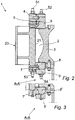
- FIG 2 a cross section is shown according to the line A-A of element 20 of the swivel 1 according to Figure 1 .
- Figure 2 shows a toro ⁇ dal chamber 2 which is defined on the interior between peripheral opposing faces of an inner annular ring 3 and the interior wall 21 of the semi-circular element 20.
- the inner annular ring 3 is the part of the swivel 1 which is adapted to be connected to a geo-stationery duct.
- the outer annular ring comprising the elements 10 and 20 can rotate with respect to the inner annular ring 3 because of the presence of a roller bearing 4.
- the swivel 1 further comprises a top inner ring 5, a top outer ring 6, a bottom outer ring 7 and two bottom rings 8 and 9, wherein the rings 3, 4, 5, 6, 7, 8 and 9 in combination with the roller bearing 4 are all bolted together using bolts 51, 52, 53 and 54.
- Other elements as shown in Figure 2 are standard elements of a swivel which will not be described in detail below.
- the semi-circular element 20 has a box shaped construction and that part of the interior volume of the semi-circular element 20 is empty in order to save weight.
- the semi-circular elements 10 and 20 have a tendency to become relatively heavy.
- FIG 3 an alternative embodiment is shown of the swivel 1 according to Figure 2 wherein the form of the bottom rings 7 and 9 is amended.
- Figure 4 only the two semi-circular elements 10 and 20 are shown with the respective bolts 41, 42, 43 and 44.
- Figure 4 shows the full length of the contact areas 30 and 31 that means the contact surfaces wherein the semi-circular elements 10 and 20 are in contact with each other.
- it will be very difficult to produce semi-circular elements 10 and 20 which, once connected to each other using the bolts 41-44, will have a contact area on the inner peripheral surface which is perfect in the sense that not a single micro opening will exist between the two semi-circular elements 10, 20 when pressed together.
- the semi-circular elements 10 and 20 will, in a first instance, be connected together by using the bolts 41-44.
- the bolts will only be tightened in order to keep the semi-circular elements 10 and 20 correctly positioned one with respect to the other. That means for instance that the bolts 41-44 are pre-tensioned at the level for instance of 5-30% of their maximum pre-tension.
- the semi-circular elements 10, 20 are produced of super duplex stainless steel, for instance super duplex stainless steel Zeron 100.
- carbon steel studbolts 41, 42, 43 and 44 are used, for instance class B24 studbolts.
- the studbolts 41-44 are used to fix the semi-circular elements 10,20 together having the studbolts pre-tensioned to 5-30% of their final pre-tension level.
- this pre-tension is set to 25% of their final pre-tension level.
- the pre-tension on the studbolts 41-44 is increased to their final pre-tension level.
- the weld will be put under compression.
- the now combined semi-circular elements 10, 20 are ready to operate as the new outer annular ring of the swivel.
Landscapes
- Engineering & Computer Science (AREA)
- General Engineering & Computer Science (AREA)
- Mechanical Engineering (AREA)
- Joints Allowing Movement (AREA)
- Earth Drilling (AREA)
- Filling Or Discharging Of Gas Storage Vessels (AREA)
Claims (12)
- Verfahren zum Ersetzen eines äußeren ringförmigen Rings (10,20) eines Flüssigkeits-Drehlagers (1), wobei das Flüssigkeits-Drehlager angepasst ist, um einen Flüssigkeitsübergang durch eine drehbewegliche Schnittstelle zwischen dem Ende einer Flüssigkeitsleitung, die mit dem Meeresboden verbunden ist, und einem Produktleitungssystem auf einem Wasserfahrzeug für die Gas- und Ölproduktion zu ermöglichen, wobei das Drehlager einen inneren ringförmigen Ring (3) und einen äußeren ringförmigen Ring aufweist, wobei die Ringe mit ihren aneinander angrenzenden zylindrischen Oberflächen in enger Nähe angeordnet sind, um eine Kammer (2) zum Aufnehmen einer Flüssigkeit zwischen den peripheren, sich gegenüberliegenden Flächen des inneren ringförmigen Rings und des äußeren ringförmigen Rings zu definieren, wobei der innere ringförmige Ring angepasst ist, um mit dem Ende der Flüssigkeitsleitung verbunden zu werden und wobei der äußere ringförmige Ring angepasst ist, um mit dem Produktleitungssystem auf dem Wasserfahrzeug verbunden zu werden, wobei das Verfahren die Schritte umfasst:- Entfernen des äußeren ringförmigen Rings,- Ersetzen des äußeren ringförmigen Rings mittels zumindest zweier kreisförmiger Segmente (10, 20), um zusammen einen Ring zu bilden, und- Befestigen der zumindest zwei kreisförmigen Segmente aneinander mittels eines Befestigungsmittels (41, 42, 43, 44), um den Ersatz des äußeren ringförmigen Rings des Drehlagers zu bilden.
- Verfahren nach Anspruch 1, wobei das Verfahren den Schritt umfasst:- Befestigen des ersten kreisförmigen Segments an dem zweiten kreisförmigen Segment mittels zumindest eines ersten Bolzens.
- Verfahren nach Anspruch 1 oder 2, wobei das Verfahren den Schritt umfasst:- Verbinden und Abdichten der Kontaktlinie (30) an der inneren ringförmigen Oberfläche zwischen einem ersten und einem zweiten kreisförmigen Segmenten mittels einer Schweißnaht (33).
- Verfahren nach Anspruch 3, wobei das Verfahren den Schritt umfasst:- nach dem Verbinden der Kontaktlinie an der inneren ringförmigen Oberfläche zwischen dem ersten und dem zweiten kreisförmigen Segment mittels einer Schweißnaht, Erhöhen der Kontaktkraft an der Kontaktoberfläche zwischen dem ersten und dem zweiten kreisförmigen Segment mittels des Befestigungsmittels.
- Flüssigkeitsdrehlager zum Ermöglichen eines Flüssigkeitsübergangs durch eine drehbewegliche Schnittstelle zwischen dem Ende einer Flüssigkeitsleitung, die mit dem Meeresboden verbunden ist, und einem Produktleitungssystem auf einem Wasserfahrzeug für die Gas- und Ölproduktion, wobei das Drehlager einen inneren ringförmigen Ring (3) und einen äußeren ringförmigen Ring (10, 20) umfasst, wobei die Ringe mit ihren aneinander angrenzenden zylindrischen Oberflächen in enger Nähe angeordnet sind, um eine Kammer (2) zum Aufnehmen einer Flüssigkeit zwischen den peripheren, sich gegenüberliegenden Flächen des inneren ringförmigen Rings und des äußeren ringförmigen Rings zu definieren, wobei der innere ringförmige Ring angepasst ist, um mit dem Ende der Flüssigkeitsleitung verbunden zu werden, die sich durch den inneren Ring zu der Kammer hin erstreckt, um eine Flüssigkeitsversorgung zu oder von der Kammer zu ermöglichen, und wobei der äußere ringförmige Ring angepasst ist, um mit dem Produktleitungssystem verbunden zu werden und mit einer Leitung ausgestattet ist, um der Flüssigkeit das Fließen von oder zu der Kammer zu dem Produktleitungssystem zu ermöglichen, dadurch gekennzeichnet, dass der äußere ringförmige Ring mindestens ein erstes kreisförmiges Segment (10) und ein zweites kreisförmiges Segment (20) umfasst, wobei die Segmente zusammen einen Ring bilden, sowie Befestigungsmittel (41, 42, 43, 44) zur Befestigung der mindestens zwei kreisförmigen Segmente, um einen äußeren ringförmigen Ring des Drehlagers zu bilden.
- Drehlager nach Anspruch 5, wobei zwei verschiedene Dichtungsbarrieren zwischen dem ersten und dem zweiten kreisförmigen Segment bestehen, die aus einem permanenten Metall-an-Metall-Kontakt und einer kontinuierlichen Schweißung (33) an der inneren ringförmigen Oberfläche zwischen dem ersten und dem zweiten kreisförmigen Segment bestehen.
- Drehlager nach Anspruch 5, wobei die Befestigungsmittel mindestens einen ersten Bolzen (41, 42, 43, 44) umfassen, um ein erstes und ein zweites kreisförmiges Segment miteinander an einer ersten Kontaktoberfläche (30, 31) zu befestigen.
- Drehlager nach Anspruch 5 oder 7, wobei die ersten und die zweiten kreisförmigen Segmente mittels einer Schweißnaht (33) verbunden sind, die an der inneren ringförmigen Oberfläche zwischen dem ersten und dem zweiten kreisförmigen Segment positioniert ist.
- Drehlager nach den Ansprüchen 5 bis 8, wobei der äußere ringförmige Ring ein erstes und eine zweites halbkreisförmiges Element umfasst.
- Drehlager nach einem der Ansprüche 5 bis 9, wobei der äußere ringförmige Ring Superduplex-Edelstahl umfasst.
- Turmaufbau, der es einem Wasserfahrzeug für die Gas- und Ölproduktion ermöglicht, am Ende einer geostationären Flüssigkeitsleitung angeschlossen zu werden und der es dem Produktleitungssystem auf dem Wasserfahrzeug ermöglicht, am Ende einer geostationären Flüssigkeitsleitung mittels einer drehbeweglichen Schnittstelle angeschlossen zu werden, wobei der Turmaufbau ein Drehlager (1) nach einem der Ansprüche 5 bis 10 umfasst.
- Wasserfahrzeug, umfassend den Turmaufbau nach Anspruch 11.
Priority Applications (1)
| Application Number | Priority Date | Filing Date | Title |
|---|---|---|---|
| EP11721045.0A EP2590853B1 (de) | 2010-07-07 | 2011-05-24 | Verfahren zum Auswechseln eines äußeren Rings eines Drehverbinders für Fluide und Drehverbinder für Fluide |
Applications Claiming Priority (3)
| Application Number | Priority Date | Filing Date | Title |
|---|---|---|---|
| EP20100168794 EP2404821A1 (de) | 2010-07-07 | 2010-07-07 | Verfahren zum Auswechseln eines äußeren Rings eines Drehverbinders für Fluide und Drehverbinder für Fluide |
| EP11721045.0A EP2590853B1 (de) | 2010-07-07 | 2011-05-24 | Verfahren zum Auswechseln eines äußeren Rings eines Drehverbinders für Fluide und Drehverbinder für Fluide |
| PCT/EP2011/058426 WO2012004047A1 (en) | 2010-07-07 | 2011-05-24 | Method for replacing an outer annular ring of a fluid swivel and a fluid swivel |
Publications (2)
| Publication Number | Publication Date |
|---|---|
| EP2590853A1 EP2590853A1 (de) | 2013-05-15 |
| EP2590853B1 true EP2590853B1 (de) | 2016-04-13 |
Family
ID=43242495
Family Applications (2)
| Application Number | Title | Priority Date | Filing Date |
|---|---|---|---|
| EP20100168794 Withdrawn EP2404821A1 (de) | 2010-07-07 | 2010-07-07 | Verfahren zum Auswechseln eines äußeren Rings eines Drehverbinders für Fluide und Drehverbinder für Fluide |
| EP11721045.0A Not-in-force EP2590853B1 (de) | 2010-07-07 | 2011-05-24 | Verfahren zum Auswechseln eines äußeren Rings eines Drehverbinders für Fluide und Drehverbinder für Fluide |
Family Applications Before (1)
| Application Number | Title | Priority Date | Filing Date |
|---|---|---|---|
| EP20100168794 Withdrawn EP2404821A1 (de) | 2010-07-07 | 2010-07-07 | Verfahren zum Auswechseln eines äußeren Rings eines Drehverbinders für Fluide und Drehverbinder für Fluide |
Country Status (7)
| Country | Link |
|---|---|
| US (1) | US9822911B2 (de) |
| EP (2) | EP2404821A1 (de) |
| CN (1) | CN102958796B (de) |
| AU (1) | AU2011276073B2 (de) |
| BR (1) | BR112013000292B1 (de) |
| CA (1) | CA2801219C (de) |
| WO (1) | WO2012004047A1 (de) |
Families Citing this family (6)
| Publication number | Priority date | Publication date | Assignee | Title |
|---|---|---|---|---|
| US8950349B2 (en) | 2012-08-17 | 2015-02-10 | Sofec, Inc. | Replaceable roller bearing |
| WO2015091266A1 (en) * | 2013-12-18 | 2015-06-25 | Single Buoy Moorings Inc. | Swivel a decoupled central ring member |
| US9617805B1 (en) * | 2014-08-14 | 2017-04-11 | Christopher M. Lafitte | Swivel assembly and disassembly apparatuses and methods |
| CA3137366A1 (en) * | 2019-04-24 | 2020-10-29 | Single Buoy Moorings Inc. | Swivel stack for transfer of fluid across a rotary interface and method for manufacturing such a swivel stack |
| CN111244813B (zh) * | 2020-01-16 | 2020-12-22 | 罗平 | 一种接触线无损扭面器 |
| NO20230328A1 (en) * | 2023-03-24 | 2024-09-25 | Oddmund Vik | Submerged retrievable swivel for a floating structure, such as a floating windmill |
Family Cites Families (16)
| Publication number | Priority date | Publication date | Assignee | Title |
|---|---|---|---|---|
| DE2325624A1 (de) * | 1972-08-28 | 1974-12-12 | Erich Rosenthal | Vorrichtung fuer die zufuhr dosierter mengen von medien zum schmieren und kuehlen rotierender gleitflaechen |
| US4126336A (en) * | 1976-12-20 | 1978-11-21 | Exxon Production Research Company | Multiline swivel |
| US4405162A (en) * | 1981-03-05 | 1983-09-20 | Fmc Corporation | Large-diameter multi-passage swivel joint for high pressure service |
| EP0190263B1 (de) * | 1984-07-30 | 1991-02-06 | Vickers Plc | Dreheinrichtung für hochdruckmittel |
| US4662657A (en) * | 1985-08-30 | 1987-05-05 | Foster-Miller, Inc. | Flow system |
| GB8819823D0 (en) * | 1988-08-20 | 1988-09-21 | Vickers Plc | Pipe swivel joints |
| GB2306595B (en) * | 1995-11-01 | 1999-09-29 | Framo Eng As | High pressure fluid connector |
| GB2321508A (en) | 1997-01-22 | 1998-07-29 | Single Buoy Moorings | Sealing arrangement in a swivel joint |
| EP0864797A1 (de) * | 1997-03-14 | 1998-09-16 | Single Buoy Moorings Inc. | Drehkupplung mit verringerter Druckfläche |
| EP0913324A1 (de) * | 1997-10-28 | 1999-05-06 | Single Buoy Moorings Inc. | Schiff mit Drehgelenkvorrichtung |
| BR9904806B1 (pt) * | 1998-01-20 | 2010-08-24 | processos de solda de duas estruturas geralmente em forma de haste e de substituiÇço ou reparo de um elemento de vedaÇço de um rodÍzio. | |
| GB2336417B (en) * | 1998-03-13 | 2000-03-29 | Bluewater Terminal Systems Nv | Fluid transfer arrangement |
| DE19919728C1 (de) * | 1999-04-30 | 2000-11-23 | Sikla Gmbh & Co Kg | Rohrkupplung |
| BR0015116A (pt) * | 1999-10-27 | 2002-06-25 | Single Buoy Moorings | Construção flutuante |
| WO2002008649A2 (en) * | 2000-07-25 | 2002-01-31 | Fmc Technologies, Inc. | High pressure product swivel |
| US7086131B2 (en) * | 2004-05-14 | 2006-08-08 | Victaulic Company | Deformable mechanical pipe coupling |
-
2010
- 2010-07-07 EP EP20100168794 patent/EP2404821A1/de not_active Withdrawn
-
2011
- 2011-05-24 CA CA2801219A patent/CA2801219C/en active Active
- 2011-05-24 CN CN201180031941.6A patent/CN102958796B/zh not_active Expired - Fee Related
- 2011-05-24 WO PCT/EP2011/058426 patent/WO2012004047A1/en not_active Ceased
- 2011-05-24 US US13/703,419 patent/US9822911B2/en not_active Expired - Fee Related
- 2011-05-24 EP EP11721045.0A patent/EP2590853B1/de not_active Not-in-force
- 2011-05-24 BR BR112013000292-1A patent/BR112013000292B1/pt not_active IP Right Cessation
- 2011-05-24 AU AU2011276073A patent/AU2011276073B2/en not_active Ceased
Also Published As
| Publication number | Publication date |
|---|---|
| BR112013000292A2 (pt) | 2016-05-24 |
| CA2801219A1 (en) | 2012-01-12 |
| WO2012004047A1 (en) | 2012-01-12 |
| CN102958796B (zh) | 2015-11-25 |
| CN102958796A (zh) | 2013-03-06 |
| US9822911B2 (en) | 2017-11-21 |
| US20130088008A1 (en) | 2013-04-11 |
| EP2404821A1 (de) | 2012-01-11 |
| AU2011276073B2 (en) | 2016-09-22 |
| EP2590853A1 (de) | 2013-05-15 |
| AU2011276073A1 (en) | 2013-01-10 |
| BR112013000292B1 (pt) | 2020-11-17 |
| CA2801219C (en) | 2018-03-20 |
Similar Documents
| Publication | Publication Date | Title |
|---|---|---|
| EP2590853B1 (de) | Verfahren zum Auswechseln eines äußeren Rings eines Drehverbinders für Fluide und Drehverbinder für Fluide | |
| EP2250419B1 (de) | Biegsame verbindung aus zwei elementen im tandemsystem | |
| EP2142836B1 (de) | Druckisolationssystem für schlauchverbindungen | |
| EP1929193B1 (de) | Schlauch zur beförderung von kryogenen fluiden | |
| AU757247B2 (en) | Fluid transfer boom with coaxial fluid ducts | |
| US10293891B2 (en) | High pressure swivel system for turret-moored vessel | |
| JP5782053B2 (ja) | 回転界面を横切って流体を移送し得る流体スイベル | |
| EP1941202B1 (de) | Kryodrehgelenk | |
| RU2777679C1 (ru) | Шарнирное соединение для трубопроводов | |
| US11953138B2 (en) | Swivel stack for transfer of fluid across a rotary interface and method for manufacturing such a swivel stack | |
| AU2002301981B2 (en) | Fluid Transfer Boom With Coaxial Fluid Ducts |
Legal Events
| Date | Code | Title | Description |
|---|---|---|---|
| PUAI | Public reference made under article 153(3) epc to a published international application that has entered the european phase |
Free format text: ORIGINAL CODE: 0009012 |
|
| 17P | Request for examination filed |
Effective date: 20121220 |
|
| AK | Designated contracting states |
Kind code of ref document: A1 Designated state(s): AL AT BE BG CH CY CZ DE DK EE ES FI FR GB GR HR HU IE IS IT LI LT LU LV MC MK MT NL NO PL PT RO RS SE SI SK SM TR |
|
| DAX | Request for extension of the european patent (deleted) | ||
| 17Q | First examination report despatched |
Effective date: 20150302 |
|
| REG | Reference to a national code |
Ref country code: DE Ref legal event code: R079 Ref document number: 602011025268 Country of ref document: DE Free format text: PREVIOUS MAIN CLASS: B63B0021500000 Ipc: F16L0027080000 |
|
| GRAP | Despatch of communication of intention to grant a patent |
Free format text: ORIGINAL CODE: EPIDOSNIGR1 |
|
| RIC1 | Information provided on ipc code assigned before grant |
Ipc: F16L 27/08 20060101AFI20150922BHEP Ipc: B23P 6/00 20060101ALI20150922BHEP Ipc: F16L 27/087 20060101ALI20150922BHEP Ipc: B63B 22/02 20060101ALI20150922BHEP Ipc: B63B 21/50 20060101ALI20150922BHEP |
|
| INTG | Intention to grant announced |
Effective date: 20151019 |
|
| GRAS | Grant fee paid |
Free format text: ORIGINAL CODE: EPIDOSNIGR3 |
|
| GRAA | (expected) grant |
Free format text: ORIGINAL CODE: 0009210 |
|
| AK | Designated contracting states |
Kind code of ref document: B1 Designated state(s): AL AT BE BG CH CY CZ DE DK EE ES FI FR GB GR HR HU IE IS IT LI LT LU LV MC MK MT NL NO PL PT RO RS SE SI SK SM TR |
|
| REG | Reference to a national code |
Ref country code: GB Ref legal event code: FG4D |
|
| REG | Reference to a national code |
Ref country code: AT Ref legal event code: REF Ref document number: 790526 Country of ref document: AT Kind code of ref document: T Effective date: 20160415 Ref country code: CH Ref legal event code: EP |
|
| REG | Reference to a national code |
Ref country code: IE Ref legal event code: FG4D |
|
| REG | Reference to a national code |
Ref country code: DE Ref legal event code: R096 Ref document number: 602011025268 Country of ref document: DE |
|
| REG | Reference to a national code |
Ref country code: NO Ref legal event code: T2 Effective date: 20160413 |
|
| REG | Reference to a national code |
Ref country code: LT Ref legal event code: MG4D |
|
| PG25 | Lapsed in a contracting state [announced via postgrant information from national office to epo] |
Ref country code: BE Free format text: LAPSE BECAUSE OF NON-PAYMENT OF DUE FEES Effective date: 20160531 |
|
| REG | Reference to a national code |
Ref country code: AT Ref legal event code: MK05 Ref document number: 790526 Country of ref document: AT Kind code of ref document: T Effective date: 20160413 |
|
| REG | Reference to a national code |
Ref country code: NL Ref legal event code: MP Effective date: 20160413 |
|
| PG25 | Lapsed in a contracting state [announced via postgrant information from national office to epo] |
Ref country code: FI Free format text: LAPSE BECAUSE OF FAILURE TO SUBMIT A TRANSLATION OF THE DESCRIPTION OR TO PAY THE FEE WITHIN THE PRESCRIBED TIME-LIMIT Effective date: 20160413 Ref country code: LT Free format text: LAPSE BECAUSE OF FAILURE TO SUBMIT A TRANSLATION OF THE DESCRIPTION OR TO PAY THE FEE WITHIN THE PRESCRIBED TIME-LIMIT Effective date: 20160413 Ref country code: NL Free format text: LAPSE BECAUSE OF FAILURE TO SUBMIT A TRANSLATION OF THE DESCRIPTION OR TO PAY THE FEE WITHIN THE PRESCRIBED TIME-LIMIT Effective date: 20160413 Ref country code: PL Free format text: LAPSE BECAUSE OF FAILURE TO SUBMIT A TRANSLATION OF THE DESCRIPTION OR TO PAY THE FEE WITHIN THE PRESCRIBED TIME-LIMIT Effective date: 20160413 |
|
| PG25 | Lapsed in a contracting state [announced via postgrant information from national office to epo] |
Ref country code: ES Free format text: LAPSE BECAUSE OF FAILURE TO SUBMIT A TRANSLATION OF THE DESCRIPTION OR TO PAY THE FEE WITHIN THE PRESCRIBED TIME-LIMIT Effective date: 20160413 Ref country code: AT Free format text: LAPSE BECAUSE OF FAILURE TO SUBMIT A TRANSLATION OF THE DESCRIPTION OR TO PAY THE FEE WITHIN THE PRESCRIBED TIME-LIMIT Effective date: 20160413 Ref country code: SE Free format text: LAPSE BECAUSE OF FAILURE TO SUBMIT A TRANSLATION OF THE DESCRIPTION OR TO PAY THE FEE WITHIN THE PRESCRIBED TIME-LIMIT Effective date: 20160413 Ref country code: PT Free format text: LAPSE BECAUSE OF FAILURE TO SUBMIT A TRANSLATION OF THE DESCRIPTION OR TO PAY THE FEE WITHIN THE PRESCRIBED TIME-LIMIT Effective date: 20160816 Ref country code: HR Free format text: LAPSE BECAUSE OF FAILURE TO SUBMIT A TRANSLATION OF THE DESCRIPTION OR TO PAY THE FEE WITHIN THE PRESCRIBED TIME-LIMIT Effective date: 20160413 Ref country code: GR Free format text: LAPSE BECAUSE OF FAILURE TO SUBMIT A TRANSLATION OF THE DESCRIPTION OR TO PAY THE FEE WITHIN THE PRESCRIBED TIME-LIMIT Effective date: 20160714 Ref country code: RS Free format text: LAPSE BECAUSE OF FAILURE TO SUBMIT A TRANSLATION OF THE DESCRIPTION OR TO PAY THE FEE WITHIN THE PRESCRIBED TIME-LIMIT Effective date: 20160413 Ref country code: LV Free format text: LAPSE BECAUSE OF FAILURE TO SUBMIT A TRANSLATION OF THE DESCRIPTION OR TO PAY THE FEE WITHIN THE PRESCRIBED TIME-LIMIT Effective date: 20160413 |
|
| REG | Reference to a national code |
Ref country code: DE Ref legal event code: R119 Ref document number: 602011025268 Country of ref document: DE |
|
| PG25 | Lapsed in a contracting state [announced via postgrant information from national office to epo] |
Ref country code: IT Free format text: LAPSE BECAUSE OF FAILURE TO SUBMIT A TRANSLATION OF THE DESCRIPTION OR TO PAY THE FEE WITHIN THE PRESCRIBED TIME-LIMIT Effective date: 20160413 Ref country code: BE Free format text: LAPSE BECAUSE OF FAILURE TO SUBMIT A TRANSLATION OF THE DESCRIPTION OR TO PAY THE FEE WITHIN THE PRESCRIBED TIME-LIMIT Effective date: 20160413 |
|
| REG | Reference to a national code |
Ref country code: CH Ref legal event code: PL |
|
| PG25 | Lapsed in a contracting state [announced via postgrant information from national office to epo] |
Ref country code: CZ Free format text: LAPSE BECAUSE OF FAILURE TO SUBMIT A TRANSLATION OF THE DESCRIPTION OR TO PAY THE FEE WITHIN THE PRESCRIBED TIME-LIMIT Effective date: 20160413 Ref country code: RO Free format text: LAPSE BECAUSE OF FAILURE TO SUBMIT A TRANSLATION OF THE DESCRIPTION OR TO PAY THE FEE WITHIN THE PRESCRIBED TIME-LIMIT Effective date: 20160413 Ref country code: MC Free format text: LAPSE BECAUSE OF FAILURE TO SUBMIT A TRANSLATION OF THE DESCRIPTION OR TO PAY THE FEE WITHIN THE PRESCRIBED TIME-LIMIT Effective date: 20160413 Ref country code: EE Free format text: LAPSE BECAUSE OF FAILURE TO SUBMIT A TRANSLATION OF THE DESCRIPTION OR TO PAY THE FEE WITHIN THE PRESCRIBED TIME-LIMIT Effective date: 20160413 Ref country code: LI Free format text: LAPSE BECAUSE OF NON-PAYMENT OF DUE FEES Effective date: 20160531 Ref country code: CH Free format text: LAPSE BECAUSE OF NON-PAYMENT OF DUE FEES Effective date: 20160531 Ref country code: DK Free format text: LAPSE BECAUSE OF FAILURE TO SUBMIT A TRANSLATION OF THE DESCRIPTION OR TO PAY THE FEE WITHIN THE PRESCRIBED TIME-LIMIT Effective date: 20160413 Ref country code: SK Free format text: LAPSE BECAUSE OF FAILURE TO SUBMIT A TRANSLATION OF THE DESCRIPTION OR TO PAY THE FEE WITHIN THE PRESCRIBED TIME-LIMIT Effective date: 20160413 |
|
| PLBE | No opposition filed within time limit |
Free format text: ORIGINAL CODE: 0009261 |
|
| STAA | Information on the status of an ep patent application or granted ep patent |
Free format text: STATUS: NO OPPOSITION FILED WITHIN TIME LIMIT |
|
| REG | Reference to a national code |
Ref country code: IE Ref legal event code: MM4A |
|
| PG25 | Lapsed in a contracting state [announced via postgrant information from national office to epo] |
Ref country code: SM Free format text: LAPSE BECAUSE OF FAILURE TO SUBMIT A TRANSLATION OF THE DESCRIPTION OR TO PAY THE FEE WITHIN THE PRESCRIBED TIME-LIMIT Effective date: 20160413 |
|
| REG | Reference to a national code |
Ref country code: FR Ref legal event code: ST Effective date: 20170131 |
|
| 26N | No opposition filed |
Effective date: 20170116 |
|
| GBPC | Gb: european patent ceased through non-payment of renewal fee |
Effective date: 20160713 |
|
| PG25 | Lapsed in a contracting state [announced via postgrant information from national office to epo] |
Ref country code: DE Free format text: LAPSE BECAUSE OF NON-PAYMENT OF DUE FEES Effective date: 20161201 Ref country code: FR Free format text: LAPSE BECAUSE OF NON-PAYMENT OF DUE FEES Effective date: 20160613 |
|
| PG25 | Lapsed in a contracting state [announced via postgrant information from national office to epo] |
Ref country code: SI Free format text: LAPSE BECAUSE OF FAILURE TO SUBMIT A TRANSLATION OF THE DESCRIPTION OR TO PAY THE FEE WITHIN THE PRESCRIBED TIME-LIMIT Effective date: 20160413 Ref country code: GB Free format text: LAPSE BECAUSE OF NON-PAYMENT OF DUE FEES Effective date: 20160713 Ref country code: IE Free format text: LAPSE BECAUSE OF NON-PAYMENT OF DUE FEES Effective date: 20160524 |
|
| PG25 | Lapsed in a contracting state [announced via postgrant information from national office to epo] |
Ref country code: HU Free format text: LAPSE BECAUSE OF FAILURE TO SUBMIT A TRANSLATION OF THE DESCRIPTION OR TO PAY THE FEE WITHIN THE PRESCRIBED TIME-LIMIT; INVALID AB INITIO Effective date: 20110524 Ref country code: CY Free format text: LAPSE BECAUSE OF FAILURE TO SUBMIT A TRANSLATION OF THE DESCRIPTION OR TO PAY THE FEE WITHIN THE PRESCRIBED TIME-LIMIT Effective date: 20160413 |
|
| PG25 | Lapsed in a contracting state [announced via postgrant information from national office to epo] |
Ref country code: LU Free format text: LAPSE BECAUSE OF NON-PAYMENT OF DUE FEES Effective date: 20160524 Ref country code: MT Free format text: LAPSE BECAUSE OF NON-PAYMENT OF DUE FEES Effective date: 20160531 Ref country code: IS Free format text: LAPSE BECAUSE OF FAILURE TO SUBMIT A TRANSLATION OF THE DESCRIPTION OR TO PAY THE FEE WITHIN THE PRESCRIBED TIME-LIMIT Effective date: 20160413 Ref country code: MK Free format text: LAPSE BECAUSE OF FAILURE TO SUBMIT A TRANSLATION OF THE DESCRIPTION OR TO PAY THE FEE WITHIN THE PRESCRIBED TIME-LIMIT Effective date: 20160413 Ref country code: TR Free format text: LAPSE BECAUSE OF FAILURE TO SUBMIT A TRANSLATION OF THE DESCRIPTION OR TO PAY THE FEE WITHIN THE PRESCRIBED TIME-LIMIT Effective date: 20160413 |
|
| PG25 | Lapsed in a contracting state [announced via postgrant information from national office to epo] |
Ref country code: BG Free format text: LAPSE BECAUSE OF FAILURE TO SUBMIT A TRANSLATION OF THE DESCRIPTION OR TO PAY THE FEE WITHIN THE PRESCRIBED TIME-LIMIT Effective date: 20160413 |
|
| PG25 | Lapsed in a contracting state [announced via postgrant information from national office to epo] |
Ref country code: AL Free format text: LAPSE BECAUSE OF FAILURE TO SUBMIT A TRANSLATION OF THE DESCRIPTION OR TO PAY THE FEE WITHIN THE PRESCRIBED TIME-LIMIT Effective date: 20160413 |
|
| P01 | Opt-out of the competence of the unified patent court (upc) registered |
Effective date: 20230525 |
|
| PGFP | Annual fee paid to national office [announced via postgrant information from national office to epo] |
Ref country code: NO Payment date: 20230420 Year of fee payment: 13 |
|
| PG25 | Lapsed in a contracting state [announced via postgrant information from national office to epo] |
Ref country code: NO Free format text: LAPSE BECAUSE OF NON-PAYMENT OF DUE FEES Effective date: 20240531 |
|
| PG25 | Lapsed in a contracting state [announced via postgrant information from national office to epo] |
Ref country code: NO Free format text: LAPSE BECAUSE OF NON-PAYMENT OF DUE FEES Effective date: 20240531 |