EP2590472B1 - WiFi apparatus for wireless internet and wireless internet system using the same - Google Patents
WiFi apparatus for wireless internet and wireless internet system using the same Download PDFInfo
- Publication number
- EP2590472B1 EP2590472B1 EP12166571.5A EP12166571A EP2590472B1 EP 2590472 B1 EP2590472 B1 EP 2590472B1 EP 12166571 A EP12166571 A EP 12166571A EP 2590472 B1 EP2590472 B1 EP 2590472B1
- Authority
- EP
- European Patent Office
- Prior art keywords
- signal
- wifi
- signals
- mobile communication
- unit
- Prior art date
- Legal status (The legal status is an assumption and is not a legal conclusion. Google has not performed a legal analysis and makes no representation as to the accuracy of the status listed.)
- Not-in-force
Links
- 238000010295 mobile communication Methods 0.000 claims description 93
- 230000008878 coupling Effects 0.000 claims description 31
- 238000010168 coupling process Methods 0.000 claims description 31
- 238000005859 coupling reaction Methods 0.000 claims description 31
- 230000003287 optical effect Effects 0.000 claims description 5
- 230000009977 dual effect Effects 0.000 description 44
- 238000009434 installation Methods 0.000 description 11
- 230000005540 biological transmission Effects 0.000 description 6
- 238000010586 diagram Methods 0.000 description 6
- 238000012423 maintenance Methods 0.000 description 6
- 238000004891 communication Methods 0.000 description 5
- 238000007726 management method Methods 0.000 description 5
- 230000000644 propagated effect Effects 0.000 description 3
- 230000003247 decreasing effect Effects 0.000 description 1
- 238000005516 engineering process Methods 0.000 description 1
- 235000013410 fast food Nutrition 0.000 description 1
- 230000032258 transport Effects 0.000 description 1
Images


Classifications
-
- H—ELECTRICITY
- H04—ELECTRIC COMMUNICATION TECHNIQUE
- H04W—WIRELESS COMMUNICATION NETWORKS
- H04W92/00—Interfaces specially adapted for wireless communication networks
- H04W92/02—Inter-networking arrangements
-
- H—ELECTRICITY
- H04—ELECTRIC COMMUNICATION TECHNIQUE
- H04W—WIRELESS COMMUNICATION NETWORKS
- H04W88/00—Devices specially adapted for wireless communication networks, e.g. terminals, base stations or access point devices
- H04W88/08—Access point devices
- H04W88/10—Access point devices adapted for operation in multiple networks, e.g. multi-mode access points
-
- H—ELECTRICITY
- H04—ELECTRIC COMMUNICATION TECHNIQUE
- H04W—WIRELESS COMMUNICATION NETWORKS
- H04W88/00—Devices specially adapted for wireless communication networks, e.g. terminals, base stations or access point devices
- H04W88/08—Access point devices
-
- H—ELECTRICITY
- H04—ELECTRIC COMMUNICATION TECHNIQUE
- H04W—WIRELESS COMMUNICATION NETWORKS
- H04W84/00—Network topologies
- H04W84/02—Hierarchically pre-organised networks, e.g. paging networks, cellular networks, WLAN [Wireless Local Area Network] or WLL [Wireless Local Loop]
- H04W84/10—Small scale networks; Flat hierarchical networks
- H04W84/12—WLAN [Wireless Local Area Networks]
Definitions
- the present invention relates to a wireless Internet system, and more particularly, to a wireless fidelity (WiFi) apparatus for wireless Internet that may perform installation, maintenance, management, or the like by using a mobile communication relay system more efficiently, and a wireless Internet system using the WiFi apparatus for wireless Internet.
- WiFi wireless fidelity
- wireless Internet service includes a wireless local area network (LAN), wireless broadband (Wibro) as portable Internet, evolution data optimized CDMA2000 (EV-DO), and the like.
- LAN wireless local area network
- Wibro wireless broadband
- EV-DO evolution data optimized CDMA2000
- US2011/0047583 discloses an integrated wireless mobile multi-media system comprising a WiFi router for routing mobile input signals and an input Ethernet signal to respective antennas for output.
- a wireless LAN among them is called a wireless fidelity (WiFi) or wireless LAN that complies with the Institute of Electrical and Electronic Engineers (IEEE) 802.11x 1999 standards.
- WiFi wireless fidelity
- IEEE Institute of Electrical and Electronic Engineers
- the IEEE 802 standards refer to a series of LAN connections developed by the IEEE 802 committee that promote standardization of a computer communication network and protocols defined in the IEEE 802 standards.
- a reference model of the protocols defined in the IEEE 802 standards is based on a hierarchy concept of an open system interconnection (OSI) reference model, and two lower layers among 7 layers of the OSI reference model are usually standardized.
- OSI open system interconnection
- Wireless LAN service uses an industrial scientific and medical equipment (ISM) band (unpermitted band) of 2.400 to 2.483 GHz that complies with the IEEE 802.11b/g international standards; thus, wireless LAN service has frequency interference with other communication service and a narrow coverage due to low output.
- ISM industrial scientific and medical equipment
- wireless LAN service having a 2.4 GHz band is localized indoors and at a hotspot with a narrow coverage
- such wireless LAN systems may be easily interlocked with the Internet and are produced and supplied with a system specification that complies with the international standards.
- the use of wireless LAN systems has been spread owing to advantages of low price, high-speed data transmission, and the like, and at present, the IEEE 802.11g standards and the IEEE 802.11 n standards have been proposed for higher speed data transmission.
- IEEE 802.11 a there are the IEEE 802.11 a standards that use a 5 GHz band and have a transmission speed of 54 Mbps. That is, in the wireless LAN connection using a 2.4 GHz band, high-speed data transmission can be performed using an industrial, scientific and medical (ISM) band. However, for example, a service area is limited to indoors and the hotspot due to a narrow coverage of several tens of meter radius and frequency interference. In addition, in portable Internet, Wibro service having a 2.3 GHz band uses a permitted band; thus, high-speed data transmission can be performed while maintaining a wider coverage without some frequency interference and output limitations.
- ISM industrial, scientific and medical
- Such wireless LAN service is mainly provided in large-scaled book stores, fast food stores, coffee shops, airports, universities, and the like.
- WiFi uses a common frequency and thus has output limitations, and the number of smart phone subscribers increases, and more WiFi installations are provided, which cause difficulties in maintenance, management, and installation.
- a wireless Internet system that can perform WiFi AP installation, maintenance, management, and the like more efficiently by using a mobile communication relay system has been developed.
- separate signals are outputted from a plurality of ports at an AP, and signals outputted from the plurality of ports have different coverages so that a hidden node may occur due to collision with subscribers that are using the wireless Internet system.
- the present invention provides a wireless fidelity (WiFi) apparatus as defined in independent claim 1 for wireless Internet that may perform installation, maintenance, management, or the like of a WiFi access point (AP) by using a mobile communication relay system more efficiently and may solve a problem relating to a hidden node, and a wireless Internet system using the WiFi apparatus for wireless Internet.
- WiFi wireless fidelity
- a wireless fidelity (WiFi) apparatus configured or use with wireless Internet
- the WiFi apparatus including: a signal inputting unit comprising a plurality of input ports for inputting a plurality of mobile communication signals, respectively, and an input port for inputting an Ethernet signal; a signal converting unit for converting the inputted Ethernet signal into a plurality of WiFi signals; a signal coupling unit for coupling the plurality of inputted mobile communication signals to the plurality of WiFi signals converted by the signal converting unit, respectively; a signal outputting unit for outputting a plurality of coupled signals coupled by the signal coupling unit through a plurality of output ports, respectively; and a coupler configured to split each of coupled signals outputted from the signal outputting unit into at least two signals having a predetermined phase difference from each other and to output the split signals, wherein the coupler outputs a split signal that is split from one coupled signal outputted from the signal outputting unit together with a split signal that is split from another coupled signal outputted from the signal outputting
- Each of the plurality of mobile communication signals may include at least one selected from the group consisting of a second generation (2G) mobile communication signal, a third generation (3G) mobile communication signal, and a fourth generation (4G) mobile communication signal.
- 2G second generation
- 3G third generation
- 4G fourth generation
- a wireless Internet system as defined in independent claim 7 using a wireless fidelity (WiFi) apparatus for wireless Internet
- the wireless Internet system including: the WiFi apparatus including a signal inputting unit including a plurality of input ports for inputting a plurality of mobile communication signals outputted from a divider of a mobile communication relay device, respectively, and an input port for inputting an Ethernet signal, a signal converting unit for converting the inputted Ethernet signal into at least a plurality of WiFi signals, a signal coupling unit for coupling the plurality of inputted mobile communication signals to the plurality of WiFi signals converted by the signal converting unit, respectively, and a signal outputting unit for outputting a plurality of coupled signals coupled by the signal coupling unit through a plurality of output ports, respectively; a coupler configured to split each of coupled signals outputted from the signal outputting unit into at least two signals having a predetermined phase difference from each other and to output the split signals; a coaxial cable having a predetermined length for transmitting a signal
- Each of the plurality of mobile communication signals may include at least one selected from the group consisting of a second generation (2G) mobile communication signal, a third generation (3G) mobile communication signal, and a fourth generation (4G) mobile communication signal.
- 2G second generation
- 3G third generation
- 4G fourth generation
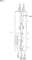
- FIG. 1 is a block diagram of a structure of a dual wireless fidelity (WiFi) apparatus for wireless Internet according to an embodiment of the present invention.
- the dual WiFi apparatus for wireless Internet may include a signal inputting unit 110, a signal converting unit 130, a signal coupling unit 150, a signal outputting unit 170, and a coupler 190.
- the dual WiFi apparatus is illustrated as an example of a WiFi apparatus for wireless Internet, the WiFi apparatus is not limited to dual outputs or inputs, and two or more outputs or inputs may be implemented.
- the signal inputting unit 110 may include a first input port 111 for inputting a first mobile communication signal, a second input port 112 for inputting a second mobile communication signal, and a third input port 113 for inputting an Ethernet signal.
- the signal inputting unit 110 includes two input ports 111 and 112 for inputting mobile communication signals.
- aspects of the present invention are not limited thereto, and the signal inputting unit 110 may include a plurality of input ports for inputting a plurality of mobile communication signals, respectively.
- the first mobile communication signal and the second mobile communication signal are coexistent, different generation signals, for example.
- the first mobile communication signal may be a second generation (2G) signal
- the second mobile communication signal may be a third generation (3G) signal, or a fourth generation (4G) signal.
- the first mobile communication signal and the second mobile communication signal as the same signal split by a divider 330 of a mobile communication relay device 310 may be a single signal having the same generation, for example, one signal among a 2G signal, a 3G signal, and a 4G signal, or a coupled signal between different generations, for example, a 2G+3G signal, a 2G+4G signal, or the like.
- the first mobile communication signal and the second mobile communication signal as the same signal are a 2G+4G signal.
- the signal converting unit 130 converts the Ethernet signal inputted through the third input port 113 of the signal inputting unit 110 into at least two WiFi signals, for example, to convert the Ethernet signal into a WiFi signal to output at least two WiFi signals and may include one WiFi module or one or more coupled WiFi modules having multiple input, multiple output (MIMO) in accordance with the IEEE 802.11n standards.
- the signal converting unit 130 may include one WiFi module in accordance with the IEEE 802.11 n standards.
- the signal coupling unit 150 couples a plurality of mobile communication signals inputted by the signal inputting unit 110 to a plurality of WiFi signals converted by the signal converting unit 130, respectively, in order to generate and output a plurality of coupled signals.
- the signal coupling unit 150 couples the first and second mobile communication signals inputted through the first input port 111 and the second input port 112 of the signal inputting unit 110 to two WiFi signals converted by the signal converting unit 130 in order to generate two 2G+4G+WiFi coupled signals, for example.
- the signal outputting unit 170 outputs the plurality of coupled signals coupled by the signal coupling unit 150 through a plurality of output ports, respectively.
- the signal outputting unit 170 may output two 2G+4G+WiFi coupled signals coupled by the signal coupling unit 150 through two, first and second output ports 171 and 172, respectively.
- the coupler 190 splits a signal outputted through the output ports into signals having a predetermined phase difference to each other and outputs the split signals in order to solve a problem relating to a hidden node that occurs in the WiFi apparatus.
- the coupler 190 may split each of the two 2G+4G+WiFi coupled signals (outputted from the signal coupling unit 150) into two signals having a 90 degree of phase difference from each other and may output the split signals through two output ports.
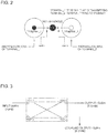
- FIG. 2 is a view for explaining a hidden node that occurs in a WiFi apparatus according to the related art.
- a signal outputted through each of a plurality of ports of the WiFi apparatus is transmitted using an existing mobile communication relay system installed in a building so that service areas in which the signal outputted through each port is propagated may not overlay each other according to the configuration of the mobile communication relay system.
- terminal 1 communicates with the WiFi apparatus in an area in which a signal outputted from port 1 of the WiFi apparatus is propagated.
- the problem relating to the hidden node refers to a phenomenon that, when a plurality of terminal devices connected to the same WiFi apparatus is in an area where the plurality of terminal devices cannot detect signals, a particular terminal device occupies a wireless LAN resource and affects the quality of service of another terminal device.
- the problem relating to the hidden node may be solved by performing signal coupling using a hybrid coupler.
- FIG. 3 is a view for explaining the principle of a coupler used in the dual WiFi apparatus for wireless Internet illustrated in FIG. 1 .
- a hybrid coupler 190 including four terminals with a 90 degree of phase difference may be used in solving the conventional problem relating to the hidden node.
- the hybrid coupler 190 may be installed in the dual WiFi apparatus for wireless Internet, as illustrated in FIG. 1 , or may be installed independently from the dual WiFi apparatus for wireless Internet.
- a 3dB directional coupler including two output terminals with a 90 degree of phase difference in the form of microstrip or strip line may be implemented in a narrow space.
- the coupler 190 includes impedance-matched terminals, and port 1 is divided into two output terminals with a 90 degree of phase difference, i.e., port 2 and port 3, and a power may not be applied to a terminal disposed at port 4.
- a two-terminal MIMO signal is connected to port 1 and port 4, respectively, and an output terminal of each of port 2 and port 3 is connected to a mobile communication network by using the coupler 190 having this shape, a signal inputted from port 1 is outputted to port 2 and port 3 with a 90 degree of phase difference, and a signal inputted from port 4 is outputted to port 2 and port 3 with a 90 degree of phase difference.
- output port 2 may output one split signal that is split from input signal of input port 1 together with one split signal that is split from input signal of input port 4 with a 90 degree of phase difference to each other
- output port 3 may output the other split signal that is split from input signal of input port 1 together with the other split signal that is split from input signal of input port 4 with a 90 degree of phase difference to each other.
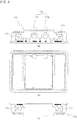
- FIGS. 4A through 4C are perspective views of an external structure of the dual WiFi apparatus 100 for wireless Internet illustrated in FIG. 1 .
- FIG. 4A is one side view of the dual WiFi apparatus 100 illustrated in FIG. 1
- FIG. 4B is a plane view of the dual WiFi apparatus 100 illustrated in FIG. 1
- FIG. 4C is the other side view of the dual WiFi apparatus 100 illustrated in FIG. 1 .
- the first input port 111, the second input port 112, and the third input port 113 for inputting an Ethernet signal of the signal inputting unit 110 are disposed on one side of the dual WiFi apparatus 100.
- the third input port 113 may include an input port 113a for inputting a power + Ethernet signal and an input port 113b for inputting the Ethernet signal.
- a first output port 171 and a second output port 172 connected to the signal outputting unit 170 or output terminals of the coupler 190 are disposed.
- the signal outputting unit 170 may receive at least one of a WiFi signal and a mobile communication signal from the coupler 190, and when the inputted signal is a WiFi + mobile communication coupled signal, the signal coupling unit 150 may split the inputted signal into the WiFi signal and the mobile communication signal, and the signal converting unit 130 may convert the split WiFi signal into the Ethernet signal, and the signal inputting unit 110 may output the converted Ethernet signal and the split mobile communication signal through the first through third input ports 111, 112, and 113.
- the signal converting unit 130 converts the inputted Ethernet signal into the WiFi signal and outputs at least two, first and second WiFi signals.
- the signal coupling unit 150 couples the first and second WiFi signals outputted from the signal converting unit 130 to the first and second 2G+4G mobile communication signals inputted by the signal inputting unit 110 in order to generate first and second 2G+4G+WiFi coupled signals, and the signal outputting unit 170 outputs the first and second 2G+4G+WiFi coupled signals to the first and second output ports 171 and 172, respectively.
- the coupler 190 splits each of the first and second 2G+4G+WiFi coupled signals outputted from the signal outputting unit 170 into two signals having a predetermined phase difference from each other and to output the split signals.
- FIG. 5 is a block diagram of a structure of a wireless Internet system using a dual WiFi apparatus for wireless Internet, according to an embodiment of the present invention.
- the wireless Internet system may include a mobile communication relay device 310, a divider 330, a dual WiFi apparatus 200, a coupler 190, a divider 350, a coaxial cable 370, and an antenna 390.
- the mobile communication relay device 310 is a device for increasing a coverage of a base station of a mobile communication network and is the same as an existing mobile communication relay device and thus, the detailed description thereof will be omitted.
- the divider 330 splits a mobile communication signal outputted from the mobile communication relay device 310 into a plurality of mobile communication signals.
- the divider 330 splits the mobile communication signal outputted from the mobile communication relay device 310 into first and second mobile communication signals.
- the dual WiFi apparatus 200 is a device configured by separating the coupler 190 from the dual WiFi apparatus 100 illustrated in FIG. 1 .
- the dual WiFi apparatus 200 may include a signal inputting unit 110 including first and second input ports 111 and 112 for inputting first and second mobile communication signals outputted from the divider 330 of the mobile communication relay device 310, respectively, and a third input port 113 for inputting an Ethernet signal via unshielded twisted pair (UTP) cables of the LAN, a signal converting unit 130 for converting the Ethernet signal inputted through the third input port 113 into at least two WiFi signals, a signal coupling unit 150 for coupling the first and second mobile communication signals inputted through the first and second input ports 111 and 112 to two WiFi signals converted by the signal converting unit 130, and a signal outputting unit 170 for outputting two coupled signals coupled by the signal coupling unit 150 to two, first and second output ports 171 and 172.
- the more detailed description thereof will be referred to FIGS. 1 and 4A through 4C described
- the coupler 190 allows each of signals outputted from the signal outputting unit 170 of the dual WiFi apparatus 200 to be split into two signals with different phase differences and to be outputted through two output ports.
- the divider 350 may include two dividers 351 and 352 for inputting two mobile communication+WiFi coupled signals outputted from the coupler 190, respectively, and the dividers 351 and 352 each split each inputted mobile communication+WiFi coupled signal into a plurality of signals and outputs the signals.
- the two mobile communication+WiFi coupled signals outputted from each of output ports of the coupler 190 have a 90 degree of phase difference from each other.
- the coaxial cable 370 includes a plurality of cables that extend a plurality of mobile communication+WiFi coupled signals outputted from the dividers 351 and 352 by a predetermined length and transmit the plurality of communication+WiFi coupled signals.
- the antenna 390 is installed at an end of each coaxial cable 370 and radiates the plurality of mobile communication+WiFi coupled signals transmitted via the plurality of coaxial cables 370 to the outside.
- the divider 350 may be detached from the wireless Internet system, and two mobile communication+WiFi coupled signals outputted from the dual WiFi apparatus 200 may be extended by a predetermined length via each coaxial cable 370 and may be radiated via each antenna 390 to the outside.
- the elements 310, 330, 200, 190, 350, 370, and 390 of the wireless Internet system illustrated in FIG. 5 have been described for forward, i.e., a direction towards a terminal from a communication system
- a 2G+4G mobile communication signal for example, outputted from the mobile communication relay device 310 is split by the divider 330 into a plurality of mobile communication signals, for example, a first 2G+4G mobile communication signal and a second 2G+4G mobile communication signal.
- the dual WiFi apparatus 200 converts the inputted Ethernet signal into a plurality of WiFi signals, for example, first and second WiFi signals, and couples the converted first and second WiFi signals to the inputted first and second 2G+4G mobile communication signals, respectively, to generate and output first and second 2G+4G+WiFi coupled signals.
- the dividers 351 and 352 each split the first and second 2G+4G+WiFi coupled signals outputted from the dual WiFi apparatus 200 into a plurality of 2G+4G+WiFi coupled signals, and each of the 2G+4G+WiFi coupled signals is transmitted to a coverage area via each coaxial cable 370 and then is radiated from each antenna 390.
- FIG. 6 is a block diagram of a structure of a dual WiFi apparatus 400 for wireless Internet according to another embodiment of the present invention.
- the dual WiFi apparatus 400 for wireless Internet may include a coupler 190 embedded in the dual WiFi apparatus 400. That is, the dual WiFi apparatus 400 for wireless Internet may include the coupler 190, a signal inputting unit 410, a signal converting unit 430, signal coupling units 451 and 452, and a signal outputting unit 470.
- the coupler 190 inputs each of signals coupled from the signal coupling units 451 and 452 through port 1 and port 4 and splits each of the inputted signals into two signals having a 90 degree of phase difference from each other, and outputs the split signals through port 2 and port 3.
- the coupler 190 has a function that is the same as or similar to the function of the coupler of FIG. 3 .
- the signal inputting unit 410 may include first and second input ports 411 and 412 for inputting first and second 2G/3G/4G mobile communication signals, a third input port 413 for inputting an Ethernet signal Ethernet_1, a fourth input port 414 for inputting an optical Ethernet signal through connection to optical cables, and an output port 415 for outputting an Ethernet signal Ethernet_2.
- the signal inputting unit 410 further includes the fourth input port 414 and the output port 415, unlike in the signal inputting unit 110 of FIG. 1 .
- the output port 415 as an Ethernet signal outputting unit transports the Ethernet signal Ethernet_1 inputted through the third input port 413 or the optical Ethernet signal inputted through the fourth input port 414 for cascade connection, to another place.
- 2G/3G/4G represents a mobile communication signal obtained by coupling one or more 2G, 3G, and 4G signals.
- the signal converting unit 430 includes one WiFi module (WiFi 2x2 802.11 n) having MIMO in accordance with the IEEE 802.11 n standards and has a function that is the same as or similar to the function of the signal converting unit 130 of FIG. 1 .
- WiFi 2x2 802.11 n WiFi 2x2 802.11 n
- the signal coupling units 451 and 452 each couple the first and second 2G/3G/4G mobile communication signals inputted through the first and second input ports 411 and 412 to two 2.4 GHz WiFi signals outputted from the signal converting unit 430 to generate two 2G/3G/4G+WiFi coupled signals and may include a band pass filter (BPF) and a diplexer, for example.
- BPF band pass filter
- the signal outputting unit 470 includes first and second output ports 471 and 472 for outputting two 2G/3G/4G+WiFi coupled signals coupled by the signal coupling units 451 and 452, respectively.
- the dual WiFi apparatus 400 of FIG. 6 may be replaced with the dual WiFi apparatus 200 and the coupler 190 in the wireless Internet system using the dual WiFi apparatus of FIG. 5 .
- the input ports of the signal inputting units 110, 410 and the output ports of the signal outputting units 170, 470 are respectively disposed on two opposite sides of the dual WiFi apparatus 100, 200, or 400 according to embodiments of the present invention.
- WiFi signals may be easily transmitted using an existing mobile communication network.
- a user uses an allocated frequency in a mobile communication relay device, there are no limitations in output of the mobile communication relay device.
- a dual WiFi apparatus with two allowed maximum outputs is installed after a divider of an output of the mobile communication relay device so that an installation point of WiFi may be minimized.
- WiFi signals are transmitted together with mobile communication signals by utilizing a coaxial cable of an existing mobile communication relay system so that installation of UTP cables may be minimized and installation, maintenance, and management, or the like of a WiFi AP (or WiFi module) may be more efficiently performed.
- signals outputted from the dual WiFi apparatus with maximum outputs are split with different phase differences and are outputted so that a problem relating to a hidden node that occurs when an MIMO signal is isolated from a plurality of terminal devices may be solved.
Landscapes
- Engineering & Computer Science (AREA)
- Computer Networks & Wireless Communication (AREA)
- Signal Processing (AREA)
- Mobile Radio Communication Systems (AREA)
- Cable Transmission Systems, Equalization Of Radio And Reduction Of Echo (AREA)
Description
- The present invention relates to a wireless Internet system, and more particularly, to a wireless fidelity (WiFi) apparatus for wireless Internet that may perform installation, maintenance, management, or the like by using a mobile communication relay system more efficiently, and a wireless Internet system using the WiFi apparatus for wireless Internet.
- In general, wireless Internet service includes a wireless local area network (LAN), wireless broadband (Wibro) as portable Internet, evolution data optimized CDMA2000 (EV-DO), and the like.
-
US2011/0047583 discloses an integrated wireless mobile multi-media system comprising a WiFi router for routing mobile input signals and an input Ethernet signal to respective antennas for output. - A wireless LAN among them is called a wireless fidelity (WiFi) or wireless LAN that complies with the Institute of Electrical and Electronic Engineers (IEEE) 802.11x 1999 standards. In the wireless LAN, an access point (AP) is connected to a wired LAN and a mobile terminal, a notebook computer, or the like is wirelessly connected to the AP and is connected to the Internet. Here, the IEEE 802 standards refer to a series of LAN connections developed by the IEEE 802 committee that promote standardization of a computer communication network and protocols defined in the IEEE 802 standards. A reference model of the protocols defined in the IEEE 802 standards is based on a hierarchy concept of an open system interconnection (OSI) reference model, and two lower layers among 7 layers of the OSI reference model are usually standardized.
- Wireless LAN service uses an industrial scientific and medical equipment (ISM) band (unpermitted band) of 2.400 to 2.483 GHz that complies with the IEEE 802.11b/g international standards; thus, wireless LAN service has frequency interference with other communication service and a narrow coverage due to low output.
- Although wireless LAN service having a 2.4 GHz band is localized indoors and at a hotspot with a narrow coverage, such wireless LAN systems may be easily interlocked with the Internet and are produced and supplied with a system specification that complies with the international standards. Thus, the use of wireless LAN systems has been spread owing to advantages of low price, high-speed data transmission, and the like, and at present, the IEEE 802.11g standards and the IEEE 802.11 n standards have been proposed for higher speed data transmission.
- In addition, there are the IEEE 802.11 a standards that use a 5 GHz band and have a transmission speed of 54 Mbps. That is, in the wireless LAN connection using a 2.4 GHz band, high-speed data transmission can be performed using an industrial, scientific and medical (ISM) band. However, for example, a service area is limited to indoors and the hotspot due to a narrow coverage of several tens of meter radius and frequency interference. In addition, in portable Internet, Wibro service having a 2.3 GHz band uses a permitted band; thus, high-speed data transmission can be performed while maintaining a wider coverage without some frequency interference and output limitations.
- Such wireless LAN service is mainly provided in large-scaled book stores, fast food stores, coffee shops, airports, universities, and the like.
- As the number of smart phone users increases and installation of WiFi as a wireless LAN is increasing, a large number of WiFi APs needs to be installed, and efficiency in conveniences of WiFi installation and maintenance, a reduction in establishment cost, or the like is required. That is, in the related art, a plurality of WiFi installations has been provided to obtain a coverage of a desired area.
- However, WiFi uses a common frequency and thus has output limitations, and the number of smart phone subscribers increases, and more WiFi installations are provided, which cause difficulties in maintenance, management, and installation. In order to solve the problems, a wireless Internet system that can perform WiFi AP installation, maintenance, management, and the like more efficiently by using a mobile communication relay system has been developed. However, in the disclosure of the wireless Internet system, separate signals are outputted from a plurality of ports at an AP, and signals outputted from the plurality of ports have different coverages so that a hidden node may occur due to collision with subscribers that are using the wireless Internet system.
- The present invention provides a wireless fidelity (WiFi) apparatus as defined in
independent claim 1 for wireless Internet that may perform installation, maintenance, management, or the like of a WiFi access point (AP) by using a mobile communication relay system more efficiently and may solve a problem relating to a hidden node, and a wireless Internet system using the WiFi apparatus for wireless Internet. - According to an aspect of the present invention, there is provided a wireless fidelity (WiFi) apparatus configured or use with wireless Internet, the WiFi apparatus including: a signal inputting unit comprising a plurality of input ports for inputting a plurality of mobile communication signals, respectively, and an input port for inputting an Ethernet signal; a signal converting unit for converting the inputted Ethernet signal into a plurality of WiFi signals; a signal coupling unit for coupling the plurality of inputted mobile communication signals to the plurality of WiFi signals converted by the signal converting unit, respectively; a signal outputting unit for outputting a plurality of coupled signals coupled by the signal coupling unit through a plurality of output ports, respectively; and a coupler configured to split each of coupled signals outputted from the signal outputting unit into at least two signals having a predetermined phase difference from each other and to output the split signals, wherein the coupler outputs a split signal that is split from one coupled signal outputted from the signal outputting unit together with a split signal that is split from another coupled signal outputted from the signal outputting unit with the predetermined phase difference to each other through the same one port.
- Each of the plurality of mobile communication signals may include at least one selected from the group consisting of a second generation (2G) mobile communication signal, a third generation (3G) mobile communication signal, and a fourth generation (4G) mobile communication signal.
- According to another aspect of the present invention, there is provided a wireless Internet system as defined in independent claim 7 using a wireless fidelity (WiFi) apparatus for wireless Internet, the wireless Internet system including: the WiFi apparatus including a signal inputting unit including a plurality of input ports for inputting a plurality of mobile communication signals outputted from a divider of a mobile communication relay device, respectively, and an input port for inputting an Ethernet signal, a signal converting unit for converting the inputted Ethernet signal into at least a plurality of WiFi signals, a signal coupling unit for coupling the plurality of inputted mobile communication signals to the plurality of WiFi signals converted by the signal converting unit, respectively, and a signal outputting unit for outputting a plurality of coupled signals coupled by the signal coupling unit through a plurality of output ports, respectively; a coupler configured to split each of coupled signals outputted from the signal outputting unit into at least two signals having a predetermined phase difference from each other and to output the split signals; a coaxial cable having a predetermined length for transmitting a signal outputted from the coupler; and an antenna installed at an end of the coaxial cable and for radiating the coupled signal, wherein the coupler outputs a split signal that is split from one coupled signal outputted from the signal outputting unit together with a split signal that is split from another coupled signal outputted from the signal outputting unit with the predetermined phase difference to each other through the same one port.
- Each of the plurality of mobile communication signals may include at least one selected from the group consisting of a second generation (2G) mobile communication signal, a third generation (3G) mobile communication signal, and a fourth generation (4G) mobile communication signal.
- The above and other features and advantages of the present invention will become more apparent by describing in detail exemplary embodiments thereof with reference to the attached drawings in which:
-
FIG. 1 is a block diagram of a structure of a dual wireless fidelity (WiFi) apparatus for wireless Internet according to an embodiment of the present invention; -
FIG. 2 is a view for explaining a hidden node that occurs in a WiFi apparatus according to the related art; -
FIG. 3 is a view for explaining the principle of a coupler used in the dual WiFi apparatus for wireless Internet illustrated inFIG. 1 ; -
FIGS. 4A through 4C are perspective views of an external structure of the dual WiFi apparatus for wireless Internet illustrated inFIG. 1 ; -
FIG. 5 is a block diagram of a structure of a wireless Internet system using a dual WiFi apparatus for wireless Internet, according to an embodiment of the present invention; and -
FIG. 6 is a block diagram of a structure of a dual WiFi apparatus for wireless Internet according to another embodiment of the present invention. - The present invention will now be described more fully with reference to the accompanying drawings, in which exemplary embodiments of the invention are shown. Like reference numerals in the drawings denote like elements. In the description of the present invention, if it is determined that a detailed description of commonly-used technologies or structures related to the invention may unnecessarily obscure the subject matter of the invention, the detailed description will be omitted.
-
FIG. 1 is a block diagram of a structure of a dual wireless fidelity (WiFi) apparatus for wireless Internet according to an embodiment of the present invention. Referring toFIG. 1 , the dual WiFi apparatus for wireless Internet according to the present embodiment may include asignal inputting unit 110, asignal converting unit 130, asignal coupling unit 150, asignal outputting unit 170, and acoupler 190. Although the dual WiFi apparatus is illustrated as an example of a WiFi apparatus for wireless Internet, the WiFi apparatus is not limited to dual outputs or inputs, and two or more outputs or inputs may be implemented. - The
signal inputting unit 110 according to the present embodiment may include afirst input port 111 for inputting a first mobile communication signal, asecond input port 112 for inputting a second mobile communication signal, and athird input port 113 for inputting an Ethernet signal. In the present embodiment, thesignal inputting unit 110 includes twoinput ports signal inputting unit 110 may include a plurality of input ports for inputting a plurality of mobile communication signals, respectively. - In the present embodiment, the first mobile communication signal and the second mobile communication signal are coexistent, different generation signals, for example. For example, the first mobile communication signal may be a second generation (2G) signal, and the second mobile communication signal may be a third generation (3G) signal, or a fourth generation (4G) signal. As another example, the first mobile communication signal and the second mobile communication signal as the same signal split by a
divider 330 of a mobilecommunication relay device 310 may be a single signal having the same generation, for example, one signal among a 2G signal, a 3G signal, and a 4G signal, or a coupled signal between different generations, for example, a 2G+3G signal, a 2G+4G signal, or the like. In the present embodiment, for convenience of explanation, the first mobile communication signal and the second mobile communication signal as the same signal are a 2G+4G signal. - The
signal converting unit 130 according to the present embodiment converts the Ethernet signal inputted through thethird input port 113 of thesignal inputting unit 110 into at least two WiFi signals, for example, to convert the Ethernet signal into a WiFi signal to output at least two WiFi signals and may include one WiFi module or one or more coupled WiFi modules having multiple input, multiple output (MIMO) in accordance with the IEEE 802.11n standards. In the present embodiment, thesignal converting unit 130 may include one WiFi module in accordance with the IEEE 802.11 n standards. - The
signal coupling unit 150 according to the present embodiment couples a plurality of mobile communication signals inputted by thesignal inputting unit 110 to a plurality of WiFi signals converted by thesignal converting unit 130, respectively, in order to generate and output a plurality of coupled signals. For example, thesignal coupling unit 150 couples the first and second mobile communication signals inputted through thefirst input port 111 and thesecond input port 112 of thesignal inputting unit 110 to two WiFi signals converted by thesignal converting unit 130 in order to generate two 2G+4G+WiFi coupled signals, for example. - The
signal outputting unit 170 according to the present embodiment outputs the plurality of coupled signals coupled by thesignal coupling unit 150 through a plurality of output ports, respectively. For example, thesignal outputting unit 170 may output two 2G+4G+WiFi coupled signals coupled by thesignal coupling unit 150 through two, first andsecond output ports - The
coupler 190 according to the present embodiment splits a signal outputted through the output ports into signals having a predetermined phase difference to each other and outputs the split signals in order to solve a problem relating to a hidden node that occurs in the WiFi apparatus. For example, thecoupler 190 may split each of the two 2G+4G+WiFi coupled signals (outputted from the signal coupling unit 150) into two signals having a 90 degree of phase difference from each other and may output the split signals through two output ports. -
FIG. 2 is a view for explaining a hidden node that occurs in a WiFi apparatus according to the related art. - In a wireless Internet system that increases a coverage by using a mobile communication relay system by coupling a mobile communication signal and a WiFi signal, a signal outputted through each of a plurality of ports of the WiFi apparatus is transmitted using an existing mobile communication relay system installed in a building so that service areas in which the signal outputted through each port is propagated may not overlay each other according to the configuration of the mobile communication relay system. In this case, as illustrated in
FIG. 2 ,terminal 1 communicates with the WiFi apparatus in an area in which a signal outputted fromport 1 of the WiFi apparatus is propagated. Whenterminal 2 communicates with the WiFi apparatus in an area in which a signal outputted fromport 2 of the same WiFi apparatus is propagated, a problem relating to a hidden node may occur interminal 1, because it is difficult to check the existence ofterminal 2 that occupies theport 2. Here, the problem relating to the hidden node refers to a phenomenon that, when a plurality of terminal devices connected to the same WiFi apparatus is in an area where the plurality of terminal devices cannot detect signals, a particular terminal device occupies a wireless LAN resource and affects the quality of service of another terminal device. - In the present embodiment, the problem relating to the hidden node may be solved by performing signal coupling using a hybrid coupler.
-
FIG. 3 is a view for explaining the principle of a coupler used in the dual WiFi apparatus for wireless Internet illustrated inFIG. 1 . - In the current embodiment of the present invention, when a 1/2 power is coupled from an original signal by using the principle of a coupler in which electromagnetic alternating current (AC) signal energy is transmitted in transmission lines, as illustrated in
FIG. 3 , the original signal is decreased by half, and the concept of a divider from which a small power of -3 dBm is outputted, is applied to the coupled power. - That is, a
hybrid coupler 190 including four terminals with a 90 degree of phase difference may be used in solving the conventional problem relating to the hidden node. Thehybrid coupler 190 may be installed in the dual WiFi apparatus for wireless Internet, as illustrated inFIG. 1 , or may be installed independently from the dual WiFi apparatus for wireless Internet. In this case, a 3dB directional coupler including two output terminals with a 90 degree of phase difference in the form of microstrip or strip line may be implemented in a narrow space. In this case, thecoupler 190 includes impedance-matched terminals, andport 1 is divided into two output terminals with a 90 degree of phase difference, i.e.,port 2 andport 3, and a power may not be applied to a terminal disposed atport 4. When a two-terminal MIMO signal is connected toport 1 andport 4, respectively, and an output terminal of each ofport 2 andport 3 is connected to a mobile communication network by using thecoupler 190 having this shape, a signal inputted fromport 1 is outputted toport 2 andport 3 with a 90 degree of phase difference, and a signal inputted fromport 4 is outputted toport 2 andport 3 with a 90 degree of phase difference. - In the
hybrid coupler 190,output port 2 may output one split signal that is split from input signal ofinput port 1 together with one split signal that is split from input signal ofinput port 4 with a 90 degree of phase difference to each other, andoutput port 3 may output the other split signal that is split from input signal ofinput port 1 together with the other split signal that is split from input signal ofinput port 4 with a 90 degree of phase difference to each other. Thus, the problem relating to the hidden node that occurs when the two-terminal MIMO signal is isolated fromport 1 andport 4 may be solved. -
FIGS. 4A through 4C are perspective views of an external structure of thedual WiFi apparatus 100 for wireless Internet illustrated inFIG. 1 .FIG. 4A is one side view of thedual WiFi apparatus 100 illustrated inFIG. 1 , andFIG. 4B is a plane view of thedual WiFi apparatus 100 illustrated inFIG. 1 , andFIG. 4C is the other side view of thedual WiFi apparatus 100 illustrated inFIG. 1 . - Referring to
FIG. 4A , on one side of thedual WiFi apparatus 100, thefirst input port 111, thesecond input port 112, and thethird input port 113 for inputting an Ethernet signal of thesignal inputting unit 110 are disposed. In the present embodiment, thethird input port 113 may include aninput port 113a for inputting a power + Ethernet signal and aninput port 113b for inputting the Ethernet signal. - Referring to
FIG. 4C , on the other side of thedual WiFi apparatus 100, afirst output port 171 and asecond output port 172 connected to thesignal outputting unit 170 or output terminals of thecoupler 190 are disposed. - Although the
elements dual WiFi apparatus 100 described with reference toFIGS. 1 and4A through 4C have been described for forward signal processing in the order of the signal inputting unit 110 -> the signal converting unit 130 -> the signal coupling unit 150 -> the signal outputting unit 170 -> thecoupler 190, backward signal processing in an opposite direction to the forward direction may also be performed. For example, when backward signal processing is performed, thesignal outputting unit 170 may receive at least one of a WiFi signal and a mobile communication signal from thecoupler 190, and when the inputted signal is a WiFi + mobile communication coupled signal, thesignal coupling unit 150 may split the inputted signal into the WiFi signal and the mobile communication signal, and thesignal converting unit 130 may convert the split WiFi signal into the Ethernet signal, and thesignal inputting unit 110 may output the converted Ethernet signal and the split mobile communication signal through the first throughthird input ports - Next, an example of an operation of the
dual WiFi apparatus 100 according to the current embodiment of the present invention will be described. - First, when first and second 2G+4G mobile communication signals are inputted to the first and
second input ports signal inputting unit 110 and the Ethernet signal is inputted to thethird input port 113, thesignal converting unit 130 converts the inputted Ethernet signal into the WiFi signal and outputs at least two, first and second WiFi signals. - Subsequently, the
signal coupling unit 150 couples the first and second WiFi signals outputted from thesignal converting unit 130 to the first and second 2G+4G mobile communication signals inputted by thesignal inputting unit 110 in order to generate first and second 2G+4G+WiFi coupled signals, and thesignal outputting unit 170 outputs the first and second 2G+4G+WiFi coupled signals to the first andsecond output ports - The
coupler 190 splits each of the first and second 2G+4G+WiFi coupled signals outputted from thesignal outputting unit 170 into two signals having a predetermined phase difference from each other and to output the split signals. -
FIG. 5 is a block diagram of a structure of a wireless Internet system using a dual WiFi apparatus for wireless Internet, according to an embodiment of the present invention. The wireless Internet system according to the present embodiment may include a mobilecommunication relay device 310, adivider 330, adual WiFi apparatus 200, acoupler 190, adivider 350, acoaxial cable 370, and anantenna 390. - The mobile
communication relay device 310 according to the present embodiment is a device for increasing a coverage of a base station of a mobile communication network and is the same as an existing mobile communication relay device and thus, the detailed description thereof will be omitted. - The
divider 330 according to the present embodiment splits a mobile communication signal outputted from the mobilecommunication relay device 310 into a plurality of mobile communication signals. In the present embodiment, thedivider 330 splits the mobile communication signal outputted from the mobilecommunication relay device 310 into first and second mobile communication signals. - The
dual WiFi apparatus 200 according to the present embodiment is a device configured by separating thecoupler 190 from thedual WiFi apparatus 100 illustrated inFIG. 1 . For example, thedual WiFi apparatus 200 may include asignal inputting unit 110 including first andsecond input ports divider 330 of the mobilecommunication relay device 310, respectively, and athird input port 113 for inputting an Ethernet signal via unshielded twisted pair (UTP) cables of the LAN, asignal converting unit 130 for converting the Ethernet signal inputted through thethird input port 113 into at least two WiFi signals, asignal coupling unit 150 for coupling the first and second mobile communication signals inputted through the first andsecond input ports signal converting unit 130, and asignal outputting unit 170 for outputting two coupled signals coupled by thesignal coupling unit 150 to two, first andsecond output ports FIGS. 1 and4A through 4C described above. - The
coupler 190 allows each of signals outputted from thesignal outputting unit 170 of thedual WiFi apparatus 200 to be split into two signals with different phase differences and to be outputted through two output ports. - The
divider 350 according to the present embodiment may include twodividers coupler 190, respectively, and thedividers coupler 190 have a 90 degree of phase difference from each other. - The
coaxial cable 370 according to the present embodiment includes a plurality of cables that extend a plurality of mobile communication+WiFi coupled signals outputted from thedividers - The
antenna 390 according to the present embodiment is installed at an end of eachcoaxial cable 370 and radiates the plurality of mobile communication+WiFi coupled signals transmitted via the plurality ofcoaxial cables 370 to the outside. - In another embodiment, the
divider 350 may be detached from the wireless Internet system, and two mobile communication+WiFi coupled signals outputted from thedual WiFi apparatus 200 may be extended by a predetermined length via eachcoaxial cable 370 and may be radiated via eachantenna 390 to the outside. - Although the
elements FIG. 5 have been described for forward, i.e., a direction towards a terminal from a communication system, signal processing in the order of the mobile communication relay device 310 -> the divider 330 -> the dual WiFi apparatus 200 -> the coupler 190 -> the divider 350 -> the coaxial cable 370 -> theantenna 390, backward that is opposite to forward, i.e., a direction towards the communication system from the terminal, signal processing may also be performed. - Next, an example of an operation of the wireless Internet system using a dual WiFi apparatus for wireless Internet, according to the current embodiment of the present invention will be described.
- First, a 2G+4G mobile communication signal, for example, outputted from the mobile
communication relay device 310 is split by thedivider 330 into a plurality of mobile communication signals, for example, a first 2G+4G mobile communication signal and a second 2G+4G mobile communication signal. - Subsequently, when the first and second 2G+4G mobile communication signals outputted from the
divider 330 are inputted to thedual WiFi apparatus 200 and the Ethernet signal is inputted to thedual WiFi apparatus 200 via UTP cables of the LAN, thedual WiFi apparatus 200 converts the inputted Ethernet signal into a plurality of WiFi signals, for example, first and second WiFi signals, and couples the converted first and second WiFi signals to the inputted first and second 2G+4G mobile communication signals, respectively, to generate and output first and second 2G+4G+WiFi coupled signals. - Subsequently, the
dividers dual WiFi apparatus 200 into a plurality of 2G+4G+WiFi coupled signals, and each of the 2G+4G+WiFi coupled signals is transmitted to a coverage area via eachcoaxial cable 370 and then is radiated from eachantenna 390. -
FIG. 6 is a block diagram of a structure of adual WiFi apparatus 400 for wireless Internet according to another embodiment of the present invention. - Referring to
FIG. 6 , thedual WiFi apparatus 400 for wireless Internet may include acoupler 190 embedded in thedual WiFi apparatus 400. That is, thedual WiFi apparatus 400 for wireless Internet may include thecoupler 190, asignal inputting unit 410, asignal converting unit 430,signal coupling units signal outputting unit 470. - The
coupler 190 inputs each of signals coupled from thesignal coupling units port 1 andport 4 and splits each of the inputted signals into two signals having a 90 degree of phase difference from each other, and outputs the split signals throughport 2 andport 3. Thecoupler 190 has a function that is the same as or similar to the function of the coupler ofFIG. 3 . - The
signal inputting unit 410 may include first andsecond input ports third input port 413 for inputting an Ethernet signal Ethernet_1, afourth input port 414 for inputting an optical Ethernet signal through connection to optical cables, and anoutput port 415 for outputting an Ethernet signal Ethernet_2. Thesignal inputting unit 410 further includes thefourth input port 414 and theoutput port 415, unlike in thesignal inputting unit 110 ofFIG. 1 . Theoutput port 415 as an Ethernet signal outputting unit transports the Ethernet signal Ethernet_1 inputted through thethird input port 413 or the optical Ethernet signal inputted through thefourth input port 414 for cascade connection, to another place. In the present embodiment, 2G/3G/4G represents a mobile communication signal obtained by coupling one or more 2G, 3G, and 4G signals. - The
signal converting unit 430 includes one WiFi module (WiFi 2x2 802.11 n) having MIMO in accordance with the IEEE 802.11 n standards and has a function that is the same as or similar to the function of thesignal converting unit 130 ofFIG. 1 . - The
signal coupling units second input ports signal converting unit 430 to generate two 2G/3G/4G+WiFi coupled signals and may include a band pass filter (BPF) and a diplexer, for example. - The
signal outputting unit 470 according to the present embodiment includes first andsecond output ports signal coupling units - The
dual WiFi apparatus 400 ofFIG. 6 may be replaced with thedual WiFi apparatus 200 and thecoupler 190 in the wireless Internet system using the dual WiFi apparatus ofFIG. 5 . - The input ports of the
signal inputting units signal outputting units dual WiFi apparatus - Thus, as shown in
FIG. 5 , by installing thedual WiFi apparatus - As described above, according to the present invention, since a user uses an allocated frequency in a mobile communication relay device, there are no limitations in output of the mobile communication relay device. However, since, when a common frequency, as in WiFi, is used, there are output limitations, a dual WiFi apparatus with two allowed maximum outputs is installed after a divider of an output of the mobile communication relay device so that an installation point of WiFi may be minimized. In addition, WiFi signals are transmitted together with mobile communication signals by utilizing a coaxial cable of an existing mobile communication relay system so that installation of UTP cables may be minimized and installation, maintenance, and management, or the like of a WiFi AP (or WiFi module) may be more efficiently performed.
- Furthermore, signals outputted from the dual WiFi apparatus with maximum outputs are split with different phase differences and are outputted so that a problem relating to a hidden node that occurs when an MIMO signal is isolated from a plurality of terminal devices may be solved.
- While the present invention has been particularly shown and described with reference to exemplary embodiments thereof, it will be understood by those of ordinary skill in the art that various changes in form and details may be made therein without departing from the scope of the present invention as defined by the following claims.
Claims (13)
- A wireless fidelity, WiFi, apparatus (100) configured for use with wireless Internet, the WiFi apparatus comprising:a signal inputting unit (110) comprising a plurality of input ports (111, 112) for inputting a plurality of mobile communication signals, respectively, and an input port (113) for inputting an Ethernet signal;a signal converting unit (130) for converting the inputted Ethernet signal into a plurality of WiFi signals;
characterized by further comprisinga signal coupling unit (150) for coupling the plurality of inputted mobile communication signals to the plurality of WiFi signals converted by the signal converting unit, respectively;a signal outputting unit (170) for outputting a plurality of coupled signals coupled by the signal coupling unit (150) through a plurality of output ports (171, 172), respectively; anda coupler (190) configured to split each of coupled signals outputted from the signal outputting unit (170) into at least two signals having a predetermined phase difference from each other and to output the split signals,wherein the coupler (190) is adapted to output a split signal that is split from one coupled signal outputted from the signal outputting unit (170) together with a split signal that is split from another coupled signal outputted from the signal outputting unit (170) with the predetermined phase difference to each other through the same one port. - The WiFi apparatus of claim 1, wherein the signal converting unit comprises at least one WiFi module having multiple input, multiple output, MIMO, in accordance with the IEEE 802.11n standards.
- The WiFi apparatus of claim 1, wherein each of the plurality of mobile communication signals comprises at least one selected from the group consisting of a second generation, 2G, mobile communication signal, a third generation, 3G, mobile communication signal, and a fourth generation, 4G, mobile communication signal.
- The WiFi apparatus of claim 1, wherein the signal inputting unit further comprises an input port for inputting an optical Ethernet signal.
- The WiFi apparatus of claim 4, wherein the signal inputting unit further comprises an output port for outputting the inputted Ethernet signal.
- The WiFi apparatus of claim 1, wherein the signal inputting unit
comprises two input ports for inputting a plurality of mobile communication signals, and the signal outputting unit comprises two output ports, and each of the input ports and the output ports are disposed on two opposite sides of the WiFi apparatus. - A wireless Internet system using a WiFi apparatus configured for use with wireless Internet, the wireless Internet system comprising:the WiFi apparatus comprising a signal inputting unit comprising a plurality of input ports for inputting a plurality of mobile communication signals outputted from a divider of a mobile communication relay device, respectively, and an input port for inputting an Ethernet signal, a signal converting unit for converting the inputted Ethernet signal into at least a plurality of WiFi signals, a signal coupling unit for coupling the plurality of inputted mobile communication signals to the plurality of WiFi signals converted by the signal converting unit, respectively, and a signal outputting unit for outputting a plurality of coupled signals coupled by the signal coupling unit through a plurality of output ports, respectively;a coupler configured to split each of coupled signals outputted from the signal outputting unit into at least two signals having a predetermined phase difference from each other and to output the split signals;a coaxial cable having a predetermined length for transmitting a signal outputted from the coupler; andan antenna installed at an end of the coaxial cable and for radiating the coupled signalwherein the coupler is adapted to output a split signal that is split from one coupled signal outputted from the signal outputting unit (170) together with a split signal that is split from another coupled signal outputted from the signal outputting unit (170) with the predetermined phase difference to each other through the same one port.
- The wireless Internet system of claim 7, further comprising a divider for splitting a coupled signal outputted from each of the plurality of output ports into a plurality of coupled signals, wherein the coaxial cable comprises a plurality of coaxial cables corresponding to the plurality of coupled signals.
- The wireless Internet system of claim 7, wherein the signal converting unit of the WiFi apparatus comprises at least one WiFi module having MIMO in accordance with the IEEE 802.11n standards.
- The wireless Internet system of claim 7, wherein each of the plurality of mobile communication signals comprises at least one selected from the group consisting of a 2G mobile communication signal, a 3G mobile communication signal, and a 4G mobile communication signal.
- The wireless Internet system of claim 7, wherein the signal inputting unit of the WiFi apparatus further comprises an input port for inputting an optical Ethernet signal.
- The wireless Internet system of claim 7, wherein the signal inputting unit of the WiFi apparatus further comprises an output port for outputting the inputted Ethernet signal.
- The wireless Internet system of claim 7, wherein the signal inputting unit of the WiFi apparatus comprises two input ports for inputting a plurality of mobile communication signals, and the signal outputting unit of the WiFi apparatus comprises two output ports, and each of the input ports and the output ports are disposed on two opposite sides of the WiFi apparatus.
Applications Claiming Priority (1)
| Application Number | Priority Date | Filing Date | Title |
|---|---|---|---|
| KR1020110114173A KR101208851B1 (en) | 2011-11-03 | 2011-11-03 | Wifi apparatus and wireless internet system using the same |
Publications (2)
| Publication Number | Publication Date |
|---|---|
| EP2590472A1 EP2590472A1 (en) | 2013-05-08 |
| EP2590472B1 true EP2590472B1 (en) | 2016-12-07 |
Family
ID=46087494
Family Applications (1)
| Application Number | Title | Priority Date | Filing Date |
|---|---|---|---|
| EP12166571.5A Not-in-force EP2590472B1 (en) | 2011-11-03 | 2012-05-03 | WiFi apparatus for wireless internet and wireless internet system using the same |
Country Status (5)
| Country | Link |
|---|---|
| US (1) | US8693498B2 (en) |
| EP (1) | EP2590472B1 (en) |
| JP (1) | JP5368603B2 (en) |
| KR (1) | KR101208851B1 (en) |
| CN (1) | CN103096511B (en) |
Families Citing this family (3)
| Publication number | Priority date | Publication date | Assignee | Title |
|---|---|---|---|---|
| CN106325084A (en) * | 2015-06-25 | 2017-01-11 | 中兴通讯股份有限公司 | Intelligent home central controller, terminal, system and control method |
| CN114204697B (en) * | 2021-12-16 | 2023-10-03 | 沈阳工业大学 | A wireless energy transmission system and control method based on PT symmetry principle |
| CN114928708B (en) * | 2022-03-08 | 2024-10-22 | 平湖新纳通信技术股份有限公司 | WiFi television implementation method for large-range coverage based on coaxial network cable |
Family Cites Families (22)
| Publication number | Priority date | Publication date | Assignee | Title |
|---|---|---|---|---|
| US20050034159A1 (en) * | 2002-12-20 | 2005-02-10 | Texas Instruments Incorporated | Implementing a hybrid wireless and coaxial cable network |
| US8010061B2 (en) * | 2002-12-24 | 2011-08-30 | Agere Systems, Inc. | Combining multimedia signaling and wireless network signaling on a common communication medium |
| US8331907B2 (en) * | 2003-02-18 | 2012-12-11 | Roamware, Inc. | Integrating GSM and WiFi service in mobile communication devices |
| US7433342B2 (en) * | 2003-08-07 | 2008-10-07 | Cisco Technology, Inc. | Wireless-aware network switch and switch ASIC |
| US7966012B2 (en) * | 2004-09-09 | 2011-06-21 | Parkervision, Inc. | Wireless protocol converter |
| TW200633528A (en) * | 2005-03-09 | 2006-09-16 | Interepoch Tech Inc | Dual-function transmitting system |
| US7813451B2 (en) * | 2006-01-11 | 2010-10-12 | Mobileaccess Networks Ltd. | Apparatus and method for frequency shifting of a wireless signal and systems using frequency shifting |
| CN101034922B (en) * | 2007-04-19 | 2010-07-07 | 华为技术有限公司 | Signal mixing method, device and same-frequency band and common antenna feedback system for different systems |
| KR20100028570A (en) * | 2007-06-22 | 2010-03-12 | 클래리톤 네트웍스, 엘티디. | Method and apparatus for proividing wimax over catv, dbs, pon infrastructure |
| US8175459B2 (en) * | 2007-10-12 | 2012-05-08 | Corning Cable Systems Llc | Hybrid wireless/wired RoF transponder and hybrid RoF communication system using same |
| FR2926942A1 (en) * | 2008-01-24 | 2009-07-31 | Herve Michel Eric Breton | Unified network access point for communicating and transmitting data via e.g. telephony cable of building, has Ethernet interface realizing multi-medium unified Ethernet access point, and microcontroller managing functionalities of point |
| US20110047583A1 (en) * | 2008-02-25 | 2011-02-24 | Internet Connectivity Group, Inc. | Integrated wireless mobilemedia system |
| US8204544B2 (en) * | 2008-03-27 | 2012-06-19 | Rockstar Bidco, LP | Agile remote radio head |
| KR100997740B1 (en) * | 2008-05-08 | 2010-12-01 | 유파인테크놀러지스 주식회사 | Distributed Multiple Wireless Communication Relay System |
| KR101007009B1 (en) * | 2008-09-19 | 2011-01-12 | (주)인터브로 | Wireless Internet access repeater without signal interference |
| US8583067B2 (en) * | 2008-09-24 | 2013-11-12 | Honeywell International Inc. | Apparatus and method for improved wireless communication reliability and performance in process control systems |
| US8705417B2 (en) * | 2009-07-06 | 2014-04-22 | Cisco Technology, Inc. | In-network home gateway for hybrid fiber-coax network |
| US8428081B2 (en) * | 2010-04-06 | 2013-04-23 | Broadcom Corporation | Method and system for connector and/or cable with configurable antenna for ethernet and wireless applications |
| KR100970671B1 (en) | 2010-05-03 | 2010-07-21 | 주식회사 해일 | Unified repeater for mobile communication and wire/wireless internet |
| WO2011139047A2 (en) * | 2010-05-03 | 2011-11-10 | 주식회사 케이티 | Integrated repeater for integratedly relaying various types of communication signals, and integrated relay system |
| US8923225B2 (en) * | 2011-04-05 | 2014-12-30 | Her Majesty The Queen In Right Of Canada, As Represented By The Minister Of Industry, Through The Communications Research Centre Canada | Cognitive WiFi radio network |
| KR20130004964A (en) * | 2011-07-05 | 2013-01-15 | 주식회사 엘지유플러스 | Dual wifi apparatus and wireless internet system using the same |
-
2011
- 2011-11-03 KR KR1020110114173A patent/KR101208851B1/en active Active
-
2012
- 2012-05-03 EP EP12166571.5A patent/EP2590472B1/en not_active Not-in-force
- 2012-05-11 US US13/469,285 patent/US8693498B2/en not_active Expired - Fee Related
- 2012-05-21 JP JP2012115644A patent/JP5368603B2/en not_active Expired - Fee Related
- 2012-08-14 CN CN201210289306.4A patent/CN103096511B/en not_active Expired - Fee Related
Non-Patent Citations (1)
| Title |
|---|
| None * |
Also Published As
| Publication number | Publication date |
|---|---|
| JP5368603B2 (en) | 2013-12-18 |
| JP2013098975A (en) | 2013-05-20 |
| US20130114585A1 (en) | 2013-05-09 |
| CN103096511B (en) | 2016-03-02 |
| EP2590472A1 (en) | 2013-05-08 |
| US8693498B2 (en) | 2014-04-08 |
| CN103096511A (en) | 2013-05-08 |
| KR101208851B1 (en) | 2012-12-05 |
Similar Documents
| Publication | Publication Date | Title |
|---|---|---|
| EP2544505B1 (en) | Dual WiFi apparatus for wireless Internet and wireless Internet system using the same | |
| US11570688B2 (en) | Single channel deployment over wireless network topologies | |
| US11206714B2 (en) | Hybrid channel wireless devices and systems | |
| AU2019373420B2 (en) | Integrated leaky feeder and mesh network system | |
| CN104067534A (en) | wireless communication network | |
| JP2023157956A (en) | System and method for distributing wireless heads | |
| US8693498B2 (en) | WiFi apparatus for wireless internet and wireless internet system using the same | |
| US20180131401A1 (en) | Wireless sfp module | |
| KR20150060152A (en) | Power outlet device with Wi-Fi capabilities | |
| KR101730614B1 (en) | Method for Providing In-Building Service By Using Wideband Coupler, In-Building System And Wideband Coupler Therefor | |
| KR101718582B1 (en) | Dual WiFi Apparatus and Wireless Internet System using the same | |
| US20230144370A1 (en) | Leap frog techniques for transmitting back haul data in a mesh wireless local area network and related access points | |
| KR20130110670A (en) | Wifi apparatus and wireless internet system using the same | |
| KR101273785B1 (en) | MIMO Service System, MIMO Apparatus and Coupler for Embodying MIMO Environment In Building | |
| CN116801266B (en) | Wireless network coverage system and AP equipment | |
| CN112073309A (en) | IoT network architecture and its WDM IoT gateway | |
| CN108271170B (en) | Distributed antenna system, multi-channel signal transmission system and method | |
| CN121569439A (en) | Signal processing equipment, multimode expansion radio frequency card and radio frequency signal remote equipment | |
| KR100936000B1 (en) | In-building RF system and method based on multi-input multi-output, and apparatus applied thereto | |
| Depani et al. | Gi-Fi Technology: A Review | |
| KR20170006873A (en) | Multi-small cell multi-band distributed antenna systems | |
| KR20050059893A (en) | Wireless lan system for underground railroad |
Legal Events
| Date | Code | Title | Description |
|---|---|---|---|
| PUAI | Public reference made under article 153(3) epc to a published international application that has entered the european phase |
Free format text: ORIGINAL CODE: 0009012 |
|
| 17P | Request for examination filed |
Effective date: 20120503 |
|
| AK | Designated contracting states |
Kind code of ref document: A1 Designated state(s): AL AT BE BG CH CY CZ DE DK EE ES FI FR GB GR HR HU IE IS IT LI LT LU LV MC MK MT NL NO PL PT RO RS SE SI SK SM TR |
|
| AX | Request for extension of the european patent |
Extension state: BA ME |
|
| RBV | Designated contracting states (corrected) |
Designated state(s): AL AT BE BG CH CY CZ DE DK EE ES FI FR GB GR HR HU IE IS IT LI LT LU LV MC MK MT NL NO PL PT RO RS SE SI SK SM TR |
|
| RAP1 | Party data changed (applicant data changed or rights of an application transferred) |
Owner name: LG UPLUS CORP. |
|
| RIC1 | Information provided on ipc code assigned before grant |
Ipc: H04W 88/10 20090101AFI20160506BHEP Ipc: H04W 92/02 20090101ALI20160506BHEP |
|
| GRAP | Despatch of communication of intention to grant a patent |
Free format text: ORIGINAL CODE: EPIDOSNIGR1 |
|
| INTG | Intention to grant announced |
Effective date: 20160708 |
|
| GRAS | Grant fee paid |
Free format text: ORIGINAL CODE: EPIDOSNIGR3 |
|
| GRAA | (expected) grant |
Free format text: ORIGINAL CODE: 0009210 |
|
| AK | Designated contracting states |
Kind code of ref document: B1 Designated state(s): AL AT BE BG CH CY CZ DE DK EE ES FI FR GB GR HR HU IE IS IT LI LT LU LV MC MK MT NL NO PL PT RO RS SE SI SK SM TR |
|
| REG | Reference to a national code |
Ref country code: GB Ref legal event code: FG4D |
|
| REG | Reference to a national code |
Ref country code: CH Ref legal event code: EP Ref country code: AT Ref legal event code: REF Ref document number: 852682 Country of ref document: AT Kind code of ref document: T Effective date: 20161215 |
|
| REG | Reference to a national code |
Ref country code: IE Ref legal event code: FG4D |
|
| REG | Reference to a national code |
Ref country code: DE Ref legal event code: R096 Ref document number: 602012026230 Country of ref document: DE |
|
| PG25 | Lapsed in a contracting state [announced via postgrant information from national office to epo] |
Ref country code: LV Free format text: LAPSE BECAUSE OF FAILURE TO SUBMIT A TRANSLATION OF THE DESCRIPTION OR TO PAY THE FEE WITHIN THE PRESCRIBED TIME-LIMIT Effective date: 20161207 |
|
| REG | Reference to a national code |
Ref country code: LT Ref legal event code: MG4D |
|
| REG | Reference to a national code |
Ref country code: NL Ref legal event code: MP Effective date: 20161207 |
|
| PG25 | Lapsed in a contracting state [announced via postgrant information from national office to epo] |
Ref country code: NO Free format text: LAPSE BECAUSE OF FAILURE TO SUBMIT A TRANSLATION OF THE DESCRIPTION OR TO PAY THE FEE WITHIN THE PRESCRIBED TIME-LIMIT Effective date: 20170307 Ref country code: LT Free format text: LAPSE BECAUSE OF FAILURE TO SUBMIT A TRANSLATION OF THE DESCRIPTION OR TO PAY THE FEE WITHIN THE PRESCRIBED TIME-LIMIT Effective date: 20161207 Ref country code: GR Free format text: LAPSE BECAUSE OF FAILURE TO SUBMIT A TRANSLATION OF THE DESCRIPTION OR TO PAY THE FEE WITHIN THE PRESCRIBED TIME-LIMIT Effective date: 20170308 Ref country code: SE Free format text: LAPSE BECAUSE OF FAILURE TO SUBMIT A TRANSLATION OF THE DESCRIPTION OR TO PAY THE FEE WITHIN THE PRESCRIBED TIME-LIMIT Effective date: 20161207 |
|
| REG | Reference to a national code |
Ref country code: AT Ref legal event code: MK05 Ref document number: 852682 Country of ref document: AT Kind code of ref document: T Effective date: 20161207 |
|
| PG25 | Lapsed in a contracting state [announced via postgrant information from national office to epo] |
Ref country code: FI Free format text: LAPSE BECAUSE OF FAILURE TO SUBMIT A TRANSLATION OF THE DESCRIPTION OR TO PAY THE FEE WITHIN THE PRESCRIBED TIME-LIMIT Effective date: 20161207 Ref country code: ES Free format text: LAPSE BECAUSE OF FAILURE TO SUBMIT A TRANSLATION OF THE DESCRIPTION OR TO PAY THE FEE WITHIN THE PRESCRIBED TIME-LIMIT Effective date: 20161207 Ref country code: HR Free format text: LAPSE BECAUSE OF FAILURE TO SUBMIT A TRANSLATION OF THE DESCRIPTION OR TO PAY THE FEE WITHIN THE PRESCRIBED TIME-LIMIT Effective date: 20161207 Ref country code: RS Free format text: LAPSE BECAUSE OF FAILURE TO SUBMIT A TRANSLATION OF THE DESCRIPTION OR TO PAY THE FEE WITHIN THE PRESCRIBED TIME-LIMIT Effective date: 20161207 |
|
| PG25 | Lapsed in a contracting state [announced via postgrant information from national office to epo] |
Ref country code: NL Free format text: LAPSE BECAUSE OF FAILURE TO SUBMIT A TRANSLATION OF THE DESCRIPTION OR TO PAY THE FEE WITHIN THE PRESCRIBED TIME-LIMIT Effective date: 20161207 |
|
| PG25 | Lapsed in a contracting state [announced via postgrant information from national office to epo] |
Ref country code: RO Free format text: LAPSE BECAUSE OF FAILURE TO SUBMIT A TRANSLATION OF THE DESCRIPTION OR TO PAY THE FEE WITHIN THE PRESCRIBED TIME-LIMIT Effective date: 20161207 Ref country code: SK Free format text: LAPSE BECAUSE OF FAILURE TO SUBMIT A TRANSLATION OF THE DESCRIPTION OR TO PAY THE FEE WITHIN THE PRESCRIBED TIME-LIMIT Effective date: 20161207 Ref country code: CZ Free format text: LAPSE BECAUSE OF FAILURE TO SUBMIT A TRANSLATION OF THE DESCRIPTION OR TO PAY THE FEE WITHIN THE PRESCRIBED TIME-LIMIT Effective date: 20161207 Ref country code: EE Free format text: LAPSE BECAUSE OF FAILURE TO SUBMIT A TRANSLATION OF THE DESCRIPTION OR TO PAY THE FEE WITHIN THE PRESCRIBED TIME-LIMIT Effective date: 20161207 Ref country code: IS Free format text: LAPSE BECAUSE OF FAILURE TO SUBMIT A TRANSLATION OF THE DESCRIPTION OR TO PAY THE FEE WITHIN THE PRESCRIBED TIME-LIMIT Effective date: 20170407 |
|
| PG25 | Lapsed in a contracting state [announced via postgrant information from national office to epo] |
Ref country code: AT Free format text: LAPSE BECAUSE OF FAILURE TO SUBMIT A TRANSLATION OF THE DESCRIPTION OR TO PAY THE FEE WITHIN THE PRESCRIBED TIME-LIMIT Effective date: 20161207 Ref country code: IT Free format text: LAPSE BECAUSE OF FAILURE TO SUBMIT A TRANSLATION OF THE DESCRIPTION OR TO PAY THE FEE WITHIN THE PRESCRIBED TIME-LIMIT Effective date: 20161207 Ref country code: BE Free format text: LAPSE BECAUSE OF FAILURE TO SUBMIT A TRANSLATION OF THE DESCRIPTION OR TO PAY THE FEE WITHIN THE PRESCRIBED TIME-LIMIT Effective date: 20161207 Ref country code: LU Free format text: LAPSE BECAUSE OF NON-PAYMENT OF DUE FEES Effective date: 20170531 Ref country code: BG Free format text: LAPSE BECAUSE OF FAILURE TO SUBMIT A TRANSLATION OF THE DESCRIPTION OR TO PAY THE FEE WITHIN THE PRESCRIBED TIME-LIMIT Effective date: 20170307 Ref country code: PL Free format text: LAPSE BECAUSE OF FAILURE TO SUBMIT A TRANSLATION OF THE DESCRIPTION OR TO PAY THE FEE WITHIN THE PRESCRIBED TIME-LIMIT Effective date: 20161207 Ref country code: SM Free format text: LAPSE BECAUSE OF FAILURE TO SUBMIT A TRANSLATION OF THE DESCRIPTION OR TO PAY THE FEE WITHIN THE PRESCRIBED TIME-LIMIT Effective date: 20161207 Ref country code: PT Free format text: LAPSE BECAUSE OF FAILURE TO SUBMIT A TRANSLATION OF THE DESCRIPTION OR TO PAY THE FEE WITHIN THE PRESCRIBED TIME-LIMIT Effective date: 20170407 |
|
| REG | Reference to a national code |
Ref country code: DE Ref legal event code: R097 Ref document number: 602012026230 Country of ref document: DE |
|
| PLBE | No opposition filed within time limit |
Free format text: ORIGINAL CODE: 0009261 |
|
| STAA | Information on the status of an ep patent application or granted ep patent |
Free format text: STATUS: NO OPPOSITION FILED WITHIN TIME LIMIT |
|
| 26N | No opposition filed |
Effective date: 20170908 |
|
| REG | Reference to a national code |
Ref country code: FR Ref legal event code: PLFP Year of fee payment: 6 |
|
| PG25 | Lapsed in a contracting state [announced via postgrant information from national office to epo] |
Ref country code: DK Free format text: LAPSE BECAUSE OF FAILURE TO SUBMIT A TRANSLATION OF THE DESCRIPTION OR TO PAY THE FEE WITHIN THE PRESCRIBED TIME-LIMIT Effective date: 20161207 Ref country code: SI Free format text: LAPSE BECAUSE OF FAILURE TO SUBMIT A TRANSLATION OF THE DESCRIPTION OR TO PAY THE FEE WITHIN THE PRESCRIBED TIME-LIMIT Effective date: 20161207 |
|
| REG | Reference to a national code |
Ref country code: CH Ref legal event code: PL |
|
| PG25 | Lapsed in a contracting state [announced via postgrant information from national office to epo] |
Ref country code: MC Free format text: LAPSE BECAUSE OF FAILURE TO SUBMIT A TRANSLATION OF THE DESCRIPTION OR TO PAY THE FEE WITHIN THE PRESCRIBED TIME-LIMIT Effective date: 20161207 |
|
| REG | Reference to a national code |
Ref country code: IE Ref legal event code: MM4A |
|
| PG25 | Lapsed in a contracting state [announced via postgrant information from national office to epo] |
Ref country code: LI Free format text: LAPSE BECAUSE OF NON-PAYMENT OF DUE FEES Effective date: 20170531 Ref country code: CH Free format text: LAPSE BECAUSE OF NON-PAYMENT OF DUE FEES Effective date: 20170531 |
|
| PG25 | Lapsed in a contracting state [announced via postgrant information from national office to epo] |
Ref country code: LU Free format text: LAPSE BECAUSE OF NON-PAYMENT OF DUE FEES Effective date: 20170503 |
|
| PG25 | Lapsed in a contracting state [announced via postgrant information from national office to epo] |
Ref country code: IE Free format text: LAPSE BECAUSE OF NON-PAYMENT OF DUE FEES Effective date: 20170503 |
|
| REG | Reference to a national code |
Ref country code: FR Ref legal event code: PLFP Year of fee payment: 7 |
|
| PG25 | Lapsed in a contracting state [announced via postgrant information from national office to epo] |
Ref country code: MT Free format text: LAPSE BECAUSE OF NON-PAYMENT OF DUE FEES Effective date: 20170503 |
|
| PG25 | Lapsed in a contracting state [announced via postgrant information from national office to epo] |
Ref country code: HU Free format text: LAPSE BECAUSE OF FAILURE TO SUBMIT A TRANSLATION OF THE DESCRIPTION OR TO PAY THE FEE WITHIN THE PRESCRIBED TIME-LIMIT; INVALID AB INITIO Effective date: 20120503 |
|
| PG25 | Lapsed in a contracting state [announced via postgrant information from national office to epo] |
Ref country code: CY Free format text: LAPSE BECAUSE OF NON-PAYMENT OF DUE FEES Effective date: 20161207 |
|
| PG25 | Lapsed in a contracting state [announced via postgrant information from national office to epo] |
Ref country code: MK Free format text: LAPSE BECAUSE OF FAILURE TO SUBMIT A TRANSLATION OF THE DESCRIPTION OR TO PAY THE FEE WITHIN THE PRESCRIBED TIME-LIMIT Effective date: 20161207 |
|
| PG25 | Lapsed in a contracting state [announced via postgrant information from national office to epo] |
Ref country code: TR Free format text: LAPSE BECAUSE OF FAILURE TO SUBMIT A TRANSLATION OF THE DESCRIPTION OR TO PAY THE FEE WITHIN THE PRESCRIBED TIME-LIMIT Effective date: 20161207 |
|
| PG25 | Lapsed in a contracting state [announced via postgrant information from national office to epo] |
Ref country code: AL Free format text: LAPSE BECAUSE OF FAILURE TO SUBMIT A TRANSLATION OF THE DESCRIPTION OR TO PAY THE FEE WITHIN THE PRESCRIBED TIME-LIMIT Effective date: 20161207 |
|
| PGFP | Annual fee paid to national office [announced via postgrant information from national office to epo] |
Ref country code: FR Payment date: 20230526 Year of fee payment: 12 Ref country code: DE Payment date: 20230530 Year of fee payment: 12 |
|
| PGFP | Annual fee paid to national office [announced via postgrant information from national office to epo] |
Ref country code: GB Payment date: 20230529 Year of fee payment: 12 |
|
| REG | Reference to a national code |
Ref country code: DE Ref legal event code: R119 Ref document number: 602012026230 Country of ref document: DE |
|
| GBPC | Gb: european patent ceased through non-payment of renewal fee |
Effective date: 20240503 |
|
| PG25 | Lapsed in a contracting state [announced via postgrant information from national office to epo] |
Ref country code: DE Free format text: LAPSE BECAUSE OF NON-PAYMENT OF DUE FEES Effective date: 20241203 |
|
| PG25 | Lapsed in a contracting state [announced via postgrant information from national office to epo] |
Ref country code: FR Free format text: LAPSE BECAUSE OF NON-PAYMENT OF DUE FEES Effective date: 20240531 |
|
| PG25 | Lapsed in a contracting state [announced via postgrant information from national office to epo] |
Ref country code: GB Free format text: LAPSE BECAUSE OF NON-PAYMENT OF DUE FEES Effective date: 20240503 |