EP2590408A1 - Image calibration method and device - Google Patents
Image calibration method and device Download PDFInfo
- Publication number
- EP2590408A1 EP2590408A1 EP11800877.0A EP11800877A EP2590408A1 EP 2590408 A1 EP2590408 A1 EP 2590408A1 EP 11800877 A EP11800877 A EP 11800877A EP 2590408 A1 EP2590408 A1 EP 2590408A1
- Authority
- EP
- European Patent Office
- Prior art keywords
- line
- image
- vehicle
- images
- lines
- Prior art date
- Legal status (The legal status is an assumption and is not a legal conclusion. Google has not performed a legal analysis and makes no representation as to the accuracy of the status listed.)
- Granted
Links
Images






Classifications
-
- H—ELECTRICITY
- H04—ELECTRIC COMMUNICATION TECHNIQUE
- H04N—PICTORIAL COMMUNICATION, e.g. TELEVISION
- H04N7/00—Television systems
- H04N7/18—Closed-circuit television [CCTV] systems, i.e. systems in which the video signal is not broadcast
- H04N7/181—Closed-circuit television [CCTV] systems, i.e. systems in which the video signal is not broadcast for receiving images from a plurality of remote sources
-
- H—ELECTRICITY
- H04—ELECTRIC COMMUNICATION TECHNIQUE
- H04N—PICTORIAL COMMUNICATION, e.g. TELEVISION
- H04N17/00—Diagnosis, testing or measuring for television systems or their details
- H04N17/002—Diagnosis, testing or measuring for television systems or their details for television cameras
-
- G—PHYSICS
- G06—COMPUTING OR CALCULATING; COUNTING
- G06T—IMAGE DATA PROCESSING OR GENERATION, IN GENERAL
- G06T3/00—Geometric image transformations in the plane of the image
-
- G—PHYSICS
- G06—COMPUTING OR CALCULATING; COUNTING
- G06T—IMAGE DATA PROCESSING OR GENERATION, IN GENERAL
- G06T7/00—Image analysis
- G06T7/80—Analysis of captured images to determine intrinsic or extrinsic camera parameters, i.e. camera calibration
-
- H—ELECTRICITY
- H04—ELECTRIC COMMUNICATION TECHNIQUE
- H04N—PICTORIAL COMMUNICATION, e.g. TELEVISION
- H04N25/00—Circuitry of solid-state image sensors [SSIS]; Control thereof
- H04N25/60—Noise processing, e.g. detecting, correcting, reducing or removing noise
- H04N25/61—Noise processing, e.g. detecting, correcting, reducing or removing noise the noise originating only from the lens unit, e.g. flare, shading, vignetting or "cos4"
-
- G—PHYSICS
- G06—COMPUTING OR CALCULATING; COUNTING
- G06T—IMAGE DATA PROCESSING OR GENERATION, IN GENERAL
- G06T2207/00—Indexing scheme for image analysis or image enhancement
- G06T2207/30—Subject of image; Context of image processing
- G06T2207/30204—Marker
-
- G—PHYSICS
- G06—COMPUTING OR CALCULATING; COUNTING
- G06T—IMAGE DATA PROCESSING OR GENERATION, IN GENERAL
- G06T2207/00—Indexing scheme for image analysis or image enhancement
- G06T2207/30—Subject of image; Context of image processing
- G06T2207/30248—Vehicle exterior or interior
- G06T2207/30252—Vehicle exterior; Vicinity of vehicle
Definitions
- the present invention relates to an image calibration method and an image calibration device, and particularly relates to improvement of processing of transforming images around a vehicle taken by on-vehicle cameras into a single viewpoint-transformed composite image.
- a technique for calibrating a state of attachment of the on-vehicle camera to the vehicle For the calibration, a calibration index is provided behind the vehicle, and the driver views an image of the calibration index displayed on the on-vehicle monitor, and thereby simultaneously adjusts the state of attachment of the on-vehicle camera so that the image of the calibration index can be appropriately displayed.
- Patent Document 1 there is a technique to appropriately calibrate an image displayed on the on-vehicle monitor by performing certain computation on the image obtained using the on-vehicle camera based on the image of the calibration index.
- the calibration index needs to be placed accurately with respect to the vehicle after the vehicle is arranged, or the vehicle needs to be arranged accurately with respect to the vehicle after the calibration index is placed.
- vehicle manufacturing line facility is improved at high costs, and thus is devised to improve the accuracy of positioning between the vehicle and the calibration index.
- the calibration index needs to be placed accurately every time the calibration is performed. Thus, further labor is required.
- An object of the present invention is to provide a calibration method and an image calibration device which are capable of alleviating the degree of strictness required for a relative positional relationship between a calibration index placed on a road surface and a vehicle arranged on the road surface.
- the image calibration method and an image calibration device alleviate the degree of strictness required for the relative positional relationship between the calibration index placed on the road surface and the vehicle arranged on the road surface in the following manner.
- multiple on-vehicle cameras respectively take images of at least two lines and at least one line orthogonal to the two parallel lines which are mutually parallel and a distance between which is known
- Distortion correction is performed on the obtained images by using default internal parameters. Correction of adjusting the internal parameters is performed so that each of images of lines in the calibration index in the thus obtained distortion-corrected images (or a viewpoint-transformed composite image to be described later) by the distortion correction can form a straight line.
- New distortion-corrected images obtained by the corrected internal parameters are transformed into a single viewpoint-transformed composite image by using default external parameters.
- the external parameters are corrected so that, like the lines in the actual calibration index: images of some of the lines in the calibration index in the viewpoint-transformed composite image can be parallel to each other; images of some of the lines can be orthogonal to each other; a distance between the parallel lines can coincide with that in the actual calibration index; and the same line (arranged on a straight line) in mutually different images which corresponds to one of the lines in the calibration index can be located on a straight line.
- a first image calibration method of the present invention is an image calibration method including taking peripheral area images of peripheral areas of a vehicle respectively with multiple cameras installed on the vehicle, the peripheral areas including a calibration index provided in advance on a road surface on which the vehicle is arranged, performing distortion correction on the peripheral area images respectively taken by the cameras on the basis of internal parameters according to optical characteristics of the cameras (for example, deviation between an optical axis of an image sensor of an on-vehicle camera and an optical axis of a lens, distortion (aberration or the like) of an image formed by a lens (an image imaged by an image sensor), or the like), performing viewpoint transformation processing on multiple distortion-corrected images obtained by the distortion correction on the basis of external parameters according to states of attachment of the cameras to the vehicle (the relative positional relationship of the vehicle (three-dimensional space coordinate position), and posture (an angle of an optical axis around each axis in three dimensions)), the viewpoint transformation processing being performed so that the multiple distortion-corrected images can be processed into a single viewpoint-transformed composite
- the image calibration method is characterized as follows.
- the calibration index includes at least two lines which are mutually parallel and a distance between which is known and at least one line orthogonal to each of the two lines, and is formed so that each of the peripheral area images can include at least images corresponding to the two mutually parallel lines and an image corresponding to the one line orthogonal to each of the two lines and so that among the lines included in the calibration index, at least one line located in a shooting range of one of the cameras and at least one line located in a shooting range of a different one of the cameras can be located on a straight line.
- correction of adjusting the internal parameters is performed so that images corresponding to the two mutually parallel lines and an image corresponding to the one orthogonal line included in the distortion-corrected image can extend linearly.
- a new viewpoint-transformed composite image is obtained by using new distortion-corrected images obtained by using the corrected internal parameters.
- the correction of adjusting the external parameters is performed so that the new viewpoint-transformed composite image thus obtained can satisfy the following conditions (1) to (4):
- the calibration index in the first image calibration method of the present invention is not limited to the calibration index in this mode, and only has to be one provided in such a manner that each vehicle-periphery image includes at least images corresponding to at least two mutually parallel lines and an image corresponding to each of the two lines.
- the multiple cameras installed on the vehicle respectively take the multiple peripheral area images of the peripheral areas of the vehicle, the peripheral area image including the calibration index provided in advance on the road surface on which the vehicle is arranged.
- the distortion correction is performed on the peripheral area images respectively taken by the cameras, on the basis of the default internal parameters.
- the viewpoint transformation processing is performed on the multiple distortion-corrected images obtained by the distortion correction on the basis of the external parameters so that the multiple distortion-corrected images can be processed into the single viewpoint-transformed composite image.
- the viewpoint-transformed composite image is calibrated by adjusting the external parameters on the basis of the images of the calibration index in the viewpoint-transformed composite image.
- distortion-corrected images reflect the internal parameters.
- a default value (a common value in defiance of individual differences) which is a design value has been used as each of the internal parameters.
- the internal parameters are corrected for each of the distortion-corrected images obtained by using the internal parameters of default values, so that each image of the line in the calibration index in the distortion-corrected image can form the straight line.
- it is possible to perform distortion correction appropriate for variation in the optical characteristics of the individual cameras and the individual differences.
- a viewpoint-transformed composite image based on the default external parameters is generated by using new distortion-corrected images (each image of the line in the calibration index forms the straight line) obtained based on the internal parameters thus corrected. Since the viewpoint-transformed composite image has the high accuracy distortion corrected images from which the viewpoint-transformed composite image is generated, and thus the viewpoint-transformed composite image necessarily has high accuracy.
- the external parameters are corrected so that the viewpoint-transformed composite image can satisfy the aforementioned four conditions (1) to (4), and thereby a viewpoint-transformed composite image having further higher accuracy can be obtained.
- the aforementioned four conditions (1) to (4) do not depend on the relative positional relationship between the vehicle and the calibration index, and defines by nature the relationship (the parallelism, the orthogonality, the distance between the lines, and the linearity) only among the images of the lines in the viewpoint-transformed composite image.
- the strictness of the position of the vehicle or the posture (the direction) of the vehicle with respect to the calibration index at the time of arranging the vehicle with respect to the calibration index is not required.
- the relative positional relationship between the calibration index placed on the road surface and the vehicle arranged on the road surface only has to have accuracy (to a degree of practical level of deviation) of the position and the posture of the vehicle obtained in an ordinary operation of parking in a parking frame in a general parking lot or the like.
- the degree of strictness required for the relative positional relationship can be alleviated.
- the first image calibration method of the present invention whether or not the images corresponding to the two mutually parallel lines in each distortion-corrected image and the image corresponding to the one line orthogonal to the two lines extend linearly can be determined in the following manner. Specifically, parts of each image are made thin lines by an image processing technique, for example. Then, if differential values (inclinations) of each line at appropriate intervals approximately fall within a certain range, the line can be determined as a straight line.
- the internal parameters are corrected for the distortion-corrected images so that each image of the corresponding line can form a straight line.
- the internal parameters are corrected for the viewpoint-transformed composite image so that the image of the corresponding line can form a straight line.
- the accuracy reliability is higher in correcting each internal parameter so that the images of the lines in the distortion-corrected image can form the straight lines than in the case of correcting each internal parameter so that the images of the lines in the viewpoint-transformed composite image can form the straight lines.
- the first image calibration method of the present invention can provide calibration having higher accuracy reliability than the second image calibration method of the present invention to be described later.
- each image of the corresponding line in the distortion-corrected image for the camera has more pixels corresponding to the image than an image of the line in the corresponding image in the viewpoint-transformed composite image, regardless of whether the image in the distortion-corrected image is longer or not.
- correcting the accuracy reliability is higher in correcting each internal parameter so that the image of the line in the distortion-corrected image can form a straight line than in the case of correcting the internal parameter so that the image of the line in the viewpoint-transformed composite image can form a straight line.
- the first image calibration method of the present invention can provide calibration having higher accuracy reliability than the second image calibration method of the present invention to be described later.
- the external parameters are corrected so that the images corresponding to the mutually parallel lines in the calibration index can be mutually parallel in the viewpoint-transformed composite image, so that the distance between the images corresponding to the mutually parallel lines in the viewpoint-transformed composite image can be the known distance between the lines in the calibration index, so that the images corresponding to the mutually orthogonal lines in the calibration index can be mutually orthogonal in the viewpoint-transformed composite image, and so that the images corresponding to the line located on a straight line in the calibration index can be located on a straight line.
- Whether or not the images in the viewpoint-transformed composite image are parallel can be determined based on whether or not inclinations (differential values) of the images (approximately linear portions) corresponding to the lines coincide with each other.
- whether or not the images are orthogonal to each other can be determined based on whether or not a value of the product of the inclinations of the images corresponding to the lines is "-1" (when corresponding portions of the images are expressed in vectors, based on whether or not a value of the inner product thereof is "0").
- whether or not the images in the viewpoint-transformed composite image corresponding to the line located on a straight line in the calibration index are located on the straight line can be determined based on whether or not the inclinations of the images coincide with an intercept x (or an intercept y) at the time when the lines are expressed in the two-dimensional Cartesian system defined by the x axis and the y axis (orthogonal to the x axis).
- the internal parameters are adjusted so that the images in the distortion-corrected images corresponding to the calibration index can extend linearly.
- the calibration index is formed by the lines in comparison with the conventional calibration method performed only based on points.
- the accuracy can be improved more than in the conventional calibration in which distortions between the points are not considered.
- the at least two lines which are parallel and the distance between which is known and the at least one line orthogonal to these two lines are applied to the lines described above, and thereby the external parameters are adjusted based on the parallelism degree and the orthogonality degree of the images in the viewpoint-transformed composite image, based on the distance between the images (the lines), and so that the images corresponding to the lines located on a straight line which are overlappingly shown in the multiple images can be located on a straight line.
- highly accurate calibration can be performed all over the viewpoint-transformed composite image.
- the internal parameters are corrected based on the linearity of the images in each distortion-corrected image.
- the internal parameters are corrected based on the linearity of the images of the lines in the calibration index in the viewpoint-transformed composite image, instead of the distortion-corrected image.
- the second image calibration method of the present invention is an image calibration method including: taking peripheral area images of peripheral areas of a vehicle respectively with multiple cameras installed on the vehicle, the peripheral areas including a calibration index provided in advance on a road surface on which the vehicle is arranged, performing distortion correction on the peripheral area images respectively taken by the cameras on the basis of internal parameters according to optical characteristics of the cameras, performing viewpoint transformation processing on multiple distortion-corrected images obtained by the distortion correction on the basis of external parameters according to states of attachment of the cameras to the vehicle, the viewpoint transformation processing being performed so that the multiple distortion-corrected images can be processed into a single viewpoint-transformed composite image obtained when the vehicle is looked down from above the vehicle, and calibrating the viewpoint-transformed composite image by adjusting the external parameters on the basis of an image of the calibration index in the viewpoint-transformed composite image, in the viewpoint transformation processing.
- the image calibration method is characterized as follows.
- the calibration index includes at least two lines which are mutually parallel and a distance between which is known and at least one line orthogonal to each of the two lines, and is formed so that each of the peripheral area images can include at least images corresponding to the two mutually parallel lines and an image corresponding to the one line orthogonal to each of the two lines and so that among the lines included in the calibration index, at least one line located in a shooting range of one of the cameras and at least one line located in a shooting range of a different one of the cameras can be located on a straight line.
- correction of adjusting the internal parameters is performed so that images corresponding to the two mutually parallel lines and an image corresponding to the one orthogonal line included in the distortion-corrected image can extend linearly.
- the viewpoint-transformed composite image is obtained by using new distortion-corrected images obtained by using the corrected internal parameters.
- the correction of adjusting the external parameters is performed so that the new viewpoint-transformed composite image thus obtained can satisfy the following conditions (1) to (4):
- the first image calibration method in which the internal parameters are corrected based on the linearity of the images in each distortion-corrected image can have higher image linearity accuracy than the second image calibration method in which the internal parameters are corrected based on the linearity of the images in the viewpoint-transformed composite image, and thus can have enhanced accuracy of the internal parameters.
- a first image calibration device of the present invention is a device for implementing the first image calibration method of the present invention.
- the image calibration device includes a calibration index provided in advance on a road surface on which a vehicle is arranged, multiple cameras installed on the vehicle which take peripheral area images of peripheral areas of the vehicle, the peripheral areas including the calibration index, a distortion correction device for performing distortion correction on the peripheral area images respectively taken by the cameras, on the basis of internal parameters according to optical characteristics of the cameras, a viewpoint transformation processing device for performing viewpoint transformation processing on multiple distortion-corrected images obtained by the distortion correction on the basis of external parameters according to states of attachment of the cameras to the vehicle, the viewpoint transformation processing being performed so that the multiple distortion-corrected images can be processed into a single viewpoint-transformed composite image obtained when being looked down from above the vehicle, and a calibration device for calibrating the viewpoint-transformed composite image by adjusting the external parameters on the basis of images of the calibration index in the viewpoint-transformed composite image, in the viewpoint transformation processing performed by the viewpoint transformation processing device.
- the image calibration device is characterized as follows.
- the calibration index includes at least two lines which are mutually parallel and a distance between which is known and at least one line orthogonal to each of the two lines, and is formed so that each of the vehicle-periphery images can include at least images corresponding to the two mutually parallel lines and an image corresponding to the one line orthogonal to each of the two lines, and so that among the lines included in the calibration index, at least one line located in a shooting range of one of the cameras and at least one line located in a shooting range of a different one of the cameras can be located on a straight line.
- the calibration device includes an internal parameter correction device and an external parameter correction device.
- the internal parameter correction device performs correction of adjusting the internal parameters for the viewpoint-transformed composite image so that images corresponding to the two mutually parallel lines and an image corresponding to the one orthogonal line included in the viewpoint-transformed composite image can extend linearly.
- the external parameter correction device performs correction of adjusting the external parameters so that the new viewpoint-transformed composite image thus obtained can satisfy the following conditions (1) to (4):
- the internal parameter correction device of the calibration device performs the correction of adjusting the internal parameter so that the images corresponding to the two mutually parallel lines included in the distortion-corrected image and the image corresponding to the one orthogonal line can extend linearly.
- the external parameter correction device of the calibration device performs correction of adjusting the external parameters so that the new viewpoint-transformed composite image thus obtained can satisfy the aforementioned conditions (1) to (4).
- the internal parameters are adjusted so that the images in the distortion-corrected images corresponding to the calibration index can extend linearly.
- the calibration index is formed by the lines in comparison with the conventional calibration device using only points.
- the accuracy it is possible to improve the accuracy than in the conventional calibration in which distortion between the points is not considered.
- the at least two lines which are parallel and the distance between which is known and the at least one line orthogonal to these two lines are applied to the lines described above, and thereby the external parameters are adjusted based on the parallelism degree and the orthogonality degree of the images in the viewpoint-transformed composite image, based on the distance between the images (the lines), and so that the images corresponding to the lines located on a straight line which are overlappingly shown in the multiple images can be located on a straight line.
- highly accurate calibration can be performed all over the viewpoint-transformed composite image.
- the first image calibration device of the present invention corrects the internal parameters for the distortion-corrected images so that each image of the corresponding line can form a straight line.
- a second image calibration device of the present invention to be described later corrects the internal parameters for the viewpoint-transformed composite image so that the image of the corresponding line can form a straight line.
- the accuracy reliability is higher in correcting each internal parameter so that the images of the lines in the distortion-corrected image can form the straight lines than in the case of correcting each internal parameter so that the images of the lines in the viewpoint-transformed composite image can form the straight lines.
- the first image calibration device of the present invention can provide calibration having higher accuracy reliability than the second image calibration device of the present invention to be described later.
- the first image calibration device of the present invention corrects the internal parameters based on the linearity of the images in each distortion-corrected image.
- the second image calibration device of the present invention corrects the internal parameters based on the linearity of the images of the lines in the calibration index in the viewpoint-transformed composite image, instead of the distortion-corrected image.
- the second image calibration device of the present invention is an image calibration device including a calibration index provided in advance on a road surface on which a vehicle is arranged, multiple cameras installed on the vehicle which take peripheral area images of peripheral areas of the vehicle, the peripheral areas including the calibration index, a distortion correction device for performing distortion correction on the peripheral area images respectively taken by the cameras on the basis of internal parameters according to optical characteristics of the cameras, a viewpoint transformation processing device for performing viewpoint transformation processing on multiple distortion-corrected images obtained by the distortion correction on the basis of external parameters according to states of attachment of the cameras to the vehicle, the viewpoint transformation processing being performed so that the multiple distortion-corrected images can be processed into a single viewpoint-transformed composite image obtained when being looked down from above the vehicle, and a calibration device for calibrating the viewpoint-transformed composite image by adjusting the external parameters on the basis of images of the calibration index in the viewpoint-transformed composite image, in the viewpoint transformation processing performed by the viewpoint transformation processing device.
- the image calibration device is characterized as follows.
- the calibration index includes at least two lines which are mutually parallel and a distance between which is known and at least one line orthogonal to each of the two lines, and is formed so that each of the peripheral area images can include at least images corresponding to the two mutually parallel lines and an image corresponding to the one line orthogonal to each of the two lines, and so that among the lines included in the calibration index, at least one line located in a shooting range of one of the cameras and at least one line located in a shooting range of a different one of the cameras can be located on a straight line.
- the calibration device includes an internal parameter correction device and an external parameter correction device.
- the internal parameter correction device performs correction of adjusting the internal parameters for the viewpoint-transformed composite image so that images corresponding to the two mutually parallel lines and an image corresponding to the one orthogonal line included in the viewpoint-transformed composite image can extend linearly.
- the external parameter correction device performs correction of adjusting the external parameters so that the new viewpoint-transformed composite image thus obtained can satisfy the following conditions (1) to (4):
- the internal parameter correction device of the calibration device performs the correction of adjusting the internal parameters for the viewpoint-transformed composite image so that the images corresponding to the two mutually parallel lines included in the viewpoint-transformed composite image and the image corresponding to the one orthogonal line can extend linearly.
- the external parameter correction device of the calibration device performs the correction of adjusting the external parameters so that the new viewpoint-transformed composite image thus obtained can satisfy the aforementioned conditions (1) to (4).
- the thus configured second image calibration device according to the present invention can provide the same operation and effect as those in the aforementioned first image calibration device of the present invention.
- the first image calibration device which corrects the internal parameters based on the linearity of the images in each distortion-corrected image can have higher image linearity accuracy than the second image calibration device which corrects the internal parameters based on the linearity of the images in the viewpoint-transformed composite image, and thus can have enhanced accuracy of the internal parameters.
- FIG. 1 is a block diagram showing a configuration of an image calibration device 100 of one embodiment of the present invention.
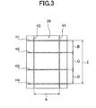
- the calibration device 100 illustrated therein includes four cameras 10 (a front-portion (front) camera 11, a rear-portion (rear) camera 12, a right-side-portion (right-side) camera 13, and a left-side-portion (left-side) camera 14), a calibration index 20 (see FIG. 3 ) to be described later drawn in advance on a road surface on which a vehicle 200 is arranged (a state where the vehicle 200 is arranged on the road surface on which the calibration index 20 is placed is shown in FIG. 5 ), a distortion correction processing unit 30 (distortion correction processing device), a viewpoint transformation processing unit 40 (viewpoint transformation processing device), and a calibration unit 50 (calibration device).
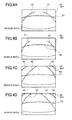
- the cameras 10 are respectively installed on a front portion, a rear portion, a right-side portion, and a left-side portion of the vehicle 200, and take images of peripheral areas R1, R2, R3, and R4 (see FIG. 2 ) of the vehicle 200 as peripheral area images S 1 (see FIG. 4A ), S2 (see FIG. 4B ), S3 (see FIG. 4C ), and S4 (see FIG. 4D ), respectively, the peripheral areas R1, R2, R3, and R4 including part of the vehicle 200 and the calibration index 20 shown in FIG. 3 .
- the distortion correction processing unit 30 performs distortion correction to remove distortion (such as aberration due to optical systems (such as lenses) included in the cameras 10) by using internal parameters M (an internal parameter M1 of the front camera 11, an internal parameter M2 of the rear camera 12, an internal parameter M3 of the right-side camera 13, and an internal parameter M4 of the left-side camera 14) according to optical characteristics of the respective cameras 11, 12, 13, and 14.
- the viewpoint transformation processing unit 40 performs view-point transformation processing on four distortion-corrected images P (a distortion-corrected image P1 corresponding to the peripheral area image S1, a distortion-corrected image P2 corresponding to the peripheral area image S2, a distortion-corrected image P3 corresponding to the peripheral area image S3, and a distortion-corrected image P4 corresponding to the peripheral area image S4) based on external parameters N (an external parameter N1 for the front camera 11, an external parameter N2 for the rear camera 12, an external parameter N3 for the right-side camera 13, and an external parameter N4 for the left-side camera 14) according to states of attachment of the cameras 10 to the vehicle 200 so that the four distortion-corrected images P can be processed into a single viewpoint-transformed composite image Q0 obtained by looking down the vehicle 200 from above.
- the calibration unit 50 calibrates the viewpoint-transformed composite image Q0 by adjusting the external parameters N based on an image of the calibration index 20 in the viewpoint-transformed composite image Q
- the calibration index 20 includes: a straight first horizontal line (a first line) H1 which is to be located in front of the vehicle 200 in the state where the vehicle 200 is arranged ( FIG. 5 ) and extends in a width direction (a vehicle width direction) of the vehicle 200; a straight fourth horizontal line (a second line) H4 which is to be located behind the vehicle 200 and extends in the vehicle width direction; a second horizontal line (a fifth line) H2 and a third horizontal line (a sixth line) H3 which are straight, are to be located between the first horizontal line H1 and the fourth horizontal line H4, and extend in the vehicle width direction; a straight first vertical line (a third line) V1 which is to be located on the right side of the vehicle 200 and extends in a front-rear direction of the vehicle 200; and a straight second vertical line (a fourth line) V2 which is to be located on the left side of the vehicle 200 and extends in the front-rear direction of the vehicle 200.
- a straight first horizontal line (a first line) H1 which is to be
- first horizontal line H1, the second horizontal line H2, the third horizontal line H3, and the fourth horizontal line H4 are parallel to each other.
- a distance between the first horizontal line H1 and the second horizontal line H2 is set at a known distance B
- a distance between the second horizontal line H2 and the third horizontal line H3 is set at a known distance C
- a distance between the third horizontal line H3 and the fourth horizontal line H4 is set at a known distance D
- a distance between the first horizontal line H1 and the fourth horizontal line H4 is set at a known distance E.
- first vertical line V1 and the second vertical line V2 are also parallel to each other and orthogonal to the horizontal lines H1, H2, H3, and H4, and a distance between the first vertical line V 1 and the second vertical line V2 is set at a known distance A.
- each of the peripheral area images S1, S2, S3, and S4 includes: ones of images H1, H2, H3, H4, V1, and V2 corresponding to at least two mutually parallel lines (two lines of the lines H1, H2, H3, and H4 or two lines of the lines V1 and V2) (the same reference numerals of the lines are used for reference numerals of the respective images to avoid complicatedness of the description, and the same applies heretofore); and one of the images V1, V2, H1 H2, H3, and H4 corresponding to one (one line of the lines V1 and V2 or one line of the lines H1, H2, H3, and H4) which is orthogonal to each of the two lines.
- the peripheral area image S 1 shows: the images V1 and V2 of the two mutually parallel vertical lines V1 and V2 among the lines H1, H2, H3, H4, V1, and V2 of the calibration index 20; and the image H1 of the one horizontal line H1 orthogonal to each of the two vertical lines V1 and V2 ( FIG. 4A ).
- peripheral area image S2 shows: the images V1 and V2 of the two mutually parallel vertical lines V1 and V2 among the lines H1, H2, H3, H4, V1, and V2 of the calibration index 20; and the image H4 of the one horizontal line H4 orthogonal to each of the two vertical lines V1 and V2 ( FIG. 4B ).
- peripheral area image S3 shows: the images H2 and H3 of the two mutually parallel horizontal lines H2 and H3 among the lines H1, H2, H3, H4, V1, and V2 of the calibration index 20; and the image V 1 of the one vertical line V1 orthogonal to each of the two horizontal lines H2 and H3 ( FIG. 4C ).
- peripheral area image S4 shows: the images H2 and H3 of the two mutually parallel horizontal lines H2 and H3 among the lines H1, H2, H3, H4, V1, and V2 of the calibration index 20; and the image V2 of the one vertical line V2 orthogonal to each of the two horizontal lines H2 and H3 ( FIG. 4D ).
- each of the peripheral area images S1, S2, S3, and S4 shows one of the images (V1, V2, H2, and H3) of the corresponding line (V1, V2, H2, and H3) which is also shown in a different one of the peripheral area images S1, S2, S3, and S4 and is located on a straight line in the calibration index 20 in reality.
- the peripheral area image S 1 shows: the image V1 of the line V 1 which is shown in the different peripheral area images S2 and S3 and is located on a straight line in the calibration index 20 in reality; and the image V2 of the line V2 which is shown in the different peripheral area images S2 and S4 and is located on a straight line in the calibration index 20 in reality.
- the peripheral area image S2 shows: the image V1 of the line V 1 which is shown in the different peripheral area images S 1 and S3 and is located on a straight line in the calibration index 20 in reality; and the image V2 of the line V2 which is shown in the different peripheral area images S1 and S4 and is located on a straight line in the calibration index 20 in reality.
- the peripheral area image S3 shows the image H1, the image H2, the image H3, and the image H4 of the respective line H1, the line H2, the line H3, and the line H4 which are shown in the different peripheral area image S4 and are located on straight lines in the calibration index 20 in reality.
- the image H1 of the line H1 shown in the peripheral area image S3 is also shown in the different peripheral area image S1
- the image H4 of the line H4 is also shown in the different peripheral area image S2.
- the peripheral area image S4 shows the image H1, the image H2, the image H3, and the image H4 of the respective line H1, the line H2, the line H3, and the line H4 which are shown in the different peripheral area image S3 and are located on straight lines in the calibration index 20 in reality.
- the image H1 of the line H1 shown in the peripheral area image S4 is also shown in the different peripheral area image S1, and the image H4 of the line H4 is also shown in the different peripheral area image S2.
- the calibration unit 50 includes an internal parameter correction unit 51 (internal parameter correction device) and an external parameter correction unit 52 (external parameter correction device). For each of the four distortion-corrected images P1 to P4, the internal parameter correction unit 51 performs a correction to adjust a corresponding one of the internal parameters M so that images corresponding to two mutually parallel lines and an image corresponding to one line orthogonal to the mutually parallel lines can extend linearly, the images being included in the corresponding one of the distortion-corrected images P1 to P4.
- the vehicle 200 shown in FIG. 2 is arranged on the flat road surface on which the calibration index 20 shown in FIG. 3 is drawn in advance as shown in FIG. 5 , the vehicle 200 having the front camera 11, the rear camera 12, the right-side camera 13, and the left-side camera 14 installed on the front, rear, right, and left portions of the vehicle 200, respectively.
- the vehicle 200 may be arranged in a straightened posture (a posture in which the front-rear direction of the vehicle 200 is parallel to the vertical lines V1 and V2 of the calibration index 20, and the width direction of the vehicle 200 is parallel to the horizontal lines H1, H2, H3, and H4 of the calibration index 20) on the center of the calibration index 20 as shown in FIG. 5 , but may be arranged in an oblique posture with respect to the calibration index 20 as shown in FIG. 10A , for example.
- the vehicle 200 may be arranged in a position deviated from the center of the calibration index 20.
- the cameras 11, 12, 13, and 14 of the calibration device 100 take images of the peripheral areas R1, R2, R3, and R4 including part of the vehicle 200 and part of the calibration index 20.
- the peripheral area images S 1 (see FIG. 4A ), S2 (see FIG. 4B ), S3 (see FIG. 4C ), and S4 (see FIG. 4D ) corresponding to the peripheral areas R1, R2, R3, and R4, respectively, are obtained by the cameras 11, 12, 13, and 14.
- the peripheral area images S1, S2, S3, and S4 obtained by the cameras 11, 12, 13, and 14 each include: the images V (or ones of the images H) corresponding to the at least two mutually parallel lines V (or ones of the lines H); and one of the images H (or the images V) corresponding to the at least one of the lines H (or the lines V) orthogonal to the mutually parallel lines V (or the lines H).
- the peripheral area image S 1 shows the images V 1 and V2 of the mutually parallel vertical lines V1 and V2 in the calibration index 20 and the image H1 of the one orthogonal horizontal line H1( FIG. 4A ).
- the peripheral area image S2 shows the images V1 and V2 of the mutually parallel vertical lines V1 and V2 in the calibration index 20 and the image H4 of the one orthogonal horizontal line H4( FIG. 4B ).
- the peripheral area image S3 shows the images H2 and H3 of the two mutually parallel horizontal lines H2 and H3 and the image V1 of the one orthogonal vertical line V1 ( FIG. 4C ).
- the peripheral area image S4 shows the images H2 and H3 of the two mutually parallel horizontal lines H2 and H3 and the image V2 of the one orthogonal vertical line V2 ( FIG. 4D ).
- the calibration index 20 should be set so that at least the line H2 and the line H3 can be taken symmetrically or that a default positional relationship between the vehicle 200 and the calibration index 20 should be set, because both the length of the line H2 and the length of the line H3 can be ensured to be long and the accuracy can be further enhanced in correction performed with ensured linearity to be described later.
- the lines H2 and H3 do not have to be necessarily symmetrical to each other in the corresponding image as illustrated in this embodiment.
- the peripheral area images S1 to S4 are inputted in the distortion correction processing unit 30.
- the distortion input processing unit 30 performs the distortion correction on the inputted peripheral area images S1 to S4 by using the default internal parameters M.
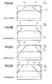
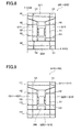
- the peripheral area images S1, S2, S3, and S4 are the distortion-corrected images P1 to P4 on which distortions have been corrected to some extent as shown in FIGs. 6A to 6D .
- each of the default internal parameters M is a design value set uniformly in defiance of individual differences of the optical characteristics of the cameras 10.
- the distortion correction using the default internal parameters M would result in the distortion-corrected images P1, P2, P3, and P4 on which distortions thereof are completely corrected.
- the cameras 10 in reality have the individual differences in the optical characteristics due to a design allowance or the like set with a manufacturing error taken into consideration.
- the internal parameters M used for the distortion correction should be different from each other by nature according to the individual cameras 10.
- the distortion correction processing unit 30 since the distortion correction processing unit 30 firstly performs the distortion correction by using the default internal parameters M, the distortions have not been completely corrected in the obtained distortion-corrected images P1, P2, P3, and P4.
- the internal parameter correction unit 51 of the calibration unit 50 corrects the default internal parameters M of the distortion correction processing unit 30.
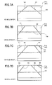
- the correction of each internal parameter M performed by the internal parameter correction unit 51 is processing in which the images H1, H2, H3, H4, V1, and V2 of the lines H1, H2, H3, H4, V1, and V2 in the calibration index 20 included in each distortion-corrected image S end up with images extending linearly as shown in FIG. 7 by serially changing a value of the internal parameter M by trial and error.
- the corrected internal parameters are obtained from the internal parameters M1, M2, M3, and M4 corresponding to the respective cameras 11, 12, 13, and 14 at the time when the images H1, H2, H3, H4, V1, and V2 of the lines H1, H2, H3, H4, V1, and V2 in the calibration index 20 included in the distortion-corrected image S end up with images extending linearly.
- the internal parameters M1 to M4 are internal parameters respectively for the cameras 11 to 14 having individual differences in optical characteristics.
- the distortion correction processing unit 30 performs the distortion correction by using the internal parameters M1 to M4 for the respective cameras 11 to 14, and thereby the peripheral area images S1, S2, S3, and S4 turn into the distortion-corrected images P11, P12, P13, and P14 on which distortions thereof have been corrected accurately as shown in FIG. 7A, FIG. 7B, FIG. 7C, and FIG. 7D , respectively.
- the viewpoint transformation processing unit 40 performs the viewpoint transformation processing according to the default external parameters N on the inputted distortion-corrected images P 11 to P 14 to generate the single viewpoint-transformed composite image Q0 shown in FIG. 8 .
- a portion corresponding to the distortion-corrected image P11 is a viewpoint-transformed partial image Q11
- a portion corresponding to the distortion-corrected image P12 is a viewpoint-transformed partial image Q12
- a portion corresponding to the distortion-corrected image P13 is a viewpoint-transformed partial image Q13
- a portion corresponding to the distortion-corrected image P14 is a viewpoint-transformed partial image Q14.
- the correction has been completed in each of the distortion-corrected images P11, P12, P13, and P14 so that the images H1, H2, H3, H4, V1, and V2 of the lines H1, H2, H3, H4, V1, and V2 of the calibration index 20 can have straight line shapes.
- the images H1, H2, H3, H4, V1, and V2 of the lines H1, H2, H3, H4, V1, and V2 of the calibration index 20 in each of the viewpoint-transformed partial images Q11 to Q14 generated based on the distortion-corrected images P11, P12, P13, and P 14 also have straight line shapes.
- the default external parameters N used in the viewpoint transformation processing performed by the viewpoint transformation processing unit 40 are design values set uniformly in defiance of individual differences of states of the attachment of the cameras 10 with respect to the vehicle 200.
- the images H1, H2, H3, H4, V1, and V2 of the lines H1, H2, H3, H4, V1, and V2 of the calibration index 20 in the viewpoint-transformed composite image Q0 obtained by the viewpoint transformation processing using the default external parameters N would be parallel to each other and distances between the images of the lines would coincide with the known values (A, B, C, D, and E), or orthogonal to each other, like the lines H1, H2, H3, H4, V1, and V2 in the calibration index 20 in reality.
- each of the images H2, H3, V1, and V2 of the lines H2, H3, V1, and V2 overlappingly shown in the viewpoint-transformed partial images Q11 to Q14 should be located on a corresponding straight line.
- the cameras 10 and the vehicle 200 in reality are each formed while having a design allowance or the like set with a manufacturing error taken into consideration, and thus naturally have individual differences in the states of the attachment of the cameras 10 to the vehicle 200, such as the attachment positions and the attachment postures.
- the external parameters N used for the viewpoint-transformation composite processing should be different from each other by nature according to the individual cameras 10.
- the viewpoint transformation processing unit 40 firstly performs the distortion correction by using the default external parameters N.
- the images H1, H2, H3, H4, V1, and V2 of the lines H1, H2, H3, H4, V1, and V2 included therein might not be parallel to each other, the distances between the images corresponding to the lines might not be appropriate, the images H1, H2, H3, H4, V1, and V2 might not be orthogonal to each other, or images of a line which should be on a straight line might not be on the straight line, as shown in FIG. 8 .
- the external parameter correction unit 52 of the calibration unit 50 corrects the default external parameters N of the viewpoint transformation processing unit 40.
- the correction of each external parameter N performed by the external parameter correction unit 52 is processing in which the images H1, H2, H3, H4, V1, and V2 of the lines H1, H2, H3, H4, V1, and V2 in the calibration index 20 included in the viewpoint-transformed composite image Q0 end up satisfying the conditions of the parallelism (the condition(1)), orthogonality (the condition (3)), the appropriateness of the distance between lines (the condition (2)), and the location on a straight line (the condition (4)) as shown in FIG. 9 by serially changing a value of the external parameter N by trial and error.
- the external parameter correction unit 41 corrects the external parameter N to specifically satisfy conditions (1-1) to (1-4) as the above condition (1), to specifically satisfy conditions (3-1) to (3-4) as the above condition (3), to specifically satisfy conditions (2-1) to (2-9) as the above condition (2), and to specifically satisfy conditions (4-1) to (4-4) as the above condition (4).
- the external parameter correction unit 41 performs the correction to adjust the external parameter N1 corresponding to the front camera 11, the external parameter N2 corresponding to the rear camera 12, the external parameter N3 corresponding to the right-side camera 13, and the external parameter N4 corresponding to the left-side camera 14 so that:
- the adjustments of the external parameters N by the external parameter correction unit 41 are preferably performed while all of the conditions (1-1) to (1-4), the conditions (3-1) to (3-4), the conditions (2-1) to (2-9), and the conditions (4-1) to (4-4) described above are completely satisfied.
- the external parameters N may also end up substantially satisfying the conditions (1-1) to (1-4), the conditions (3-1) to (3-4), the conditions (2-1) to (2-9), and the conditions (4-1) to (4-4) described above in a good balance.
- FIG. 9 shows the viewpoint-transformed composite image Q10 newly obtained by performing the viewpoint transformation processing on the distortion-corrected images P11, P 12, P13, and P14 by the viewpoint transformation processing unit 40 by use of the corrected external parameters N.
- a portion corresponding to the distortion-corrected image P11 in the viewpoint-transformed composite image Q10 is a viewpoint-transformed partial image Q21
- a portion corresponding to the distortion-corrected image P12 is a viewpoint-transformed partial image Q22
- a portion corresponding to the distortion-corrected image P13 is a viewpoint-transformed partial image Q23
- a portion corresponding to the distortion-corrected image P14 is a viewpoint-transformed partial image Q24.
- each of the images of the lines is approximated by using a linear expression in a two-dimensional Cartesian coordinate system using an x axis and a y axis in FIG. 8 , Then, it is determined whether or not inclinations (differential values) of the linear expressions are the same.
- whether or not the images of the lines are orthogonal to each other can be determined based on whether or not a value of the product of the inclinations in the aforementioned linear expressions is "-1" (when the images are expressed in vectors, based on whether or not a value of the inner product thereof is "0").
- whether or not the images in the viewpoint-transformed composite image Q0 corresponding to the line located on a straight line in the calibration index 20 are located on the straight line can be determined based on whether or not the inclinations of the images coincide with an intercept x (or an intercept y) at the time when the lines are expressed in the two-dimensional Cartesian system defined by the x axis and the y axis (orthogonal to the x axis).
- each of the external parameters N expressed as a single code corresponding to one of the cameras 10 actually consists of position parameters (three variables) for identifying positions in a three-dimensional space and direction parameters (three variables) for identifying directions in the three-dimensional space
- the internal parameters M are corrected for the distortion-corrected images P obtained by using the default values of the internal parameters M so that the images H and V of the lines H and V in the calibration index 20 in the distortion-corrected images P can form straight lines.
- distortion correction appropriate for variation of the optical characteristics and individual differences of the individual cameras 10 can be performed, and distortion-corrected images with high accuracy can be obtained.
- the viewpoint-transformed composite image Q0 based on the default values of the external parameters N is generated. Since the generated viewpoint-transformed composite image Q0 has the high accuracy distortion-corrected images P from which the viewpoint-transformed composite image Q0 is generated, and thus the viewpoint-transformed composite image Q0 necessarily has high accuracy.
- the external parameters N are corrected so that the viewpoint-transformed composite image Q0 can satisfy the aforementioned four conditions (1) to (4), and thereby the viewpoint-transformed composite image Q10 having further higher accuracy can be obtained.
- the aforementioned four conditions (1) to (4) do not depend on the relative positional relationship between the vehicle 200 and the calibration index 20, and defines by nature the relationship (the parallelism, the orthogonality, the distance between the lines, and the linearity) only among the images H and V of the lines H and V in the viewpoint-transformed composite image Q0.
- the strictness of the position of the vehicle 200 or the posture (the direction) of the vehicle 200 with respect to the calibration index 20 at the time of arranging the vehicle 200 with respect to the calibration index 20 is not required.
- the relative positional relationship between the calibration index 20 placed on the road surface and the vehicle 200 arranged on the road surface only has to have accuracy (to a degree of practical level of deviation) of the position and the posture of the vehicle 200 obtained in an ordinary operation of parking in a parking frame in a general parking lot or the like.
- the degree of strictness required for the relative positional relationship can be alleviated.
- the calibration index 20 common thereto can be used without any modification.
- a calibration index 20 dedicated for the type of the vehicle 200 does not have to be prepared and to be placed every time calibration is performed, and labor and time of the work can be considerably reduced.
- the internal parameters M are adjusted so that the images H and V in the distortion-corrected images P which correspond to the lines H and V in the calibration index 20 can extend linearly. Thereby, it is possible to achieve higher calibration than the conventional calibration in which the fixed internal parameter is used and the external parameter N is adjusted.
- the calibration index 20 is formed by the lines in comparison with the conventional calibration method performed only based on points.
- the accuracy can be improved more than in the conventional calibration in which distortions between the points are not considered.
- At least two lines parallel to each other and having a known distance between the lines and at least one line orthogonal to the two lines are applied to the lines H and V, and thereby the external parameters N are adjusted based on the degree of parallelism and the degree of orthogonality of the images H and V in the viewpoint-transformed composite image Q0, based on the distance between the images (the lines), and so that the images H and V corresponding to the lines H and V which are overlappingly shown in the at least two viewpoint-transformed partial images and located on a straight line can be located on the straight line.
- highly accurate calibration can be performed all over the viewpoint-transformed composite image Q0.
- a simple calibration index is applied to the calibration index 20.
- the simple calibration index is constituted of: the first horizontal line H1, the second horizontal line H2, the third horizontal line H3, and the fourth horizontal line H4 which extend in the vehicle width direction, are parallel to each other, and have straight line shapes; and the vertical lines V1 and V2 which are orthogonal to each of the horizontal lines H1, H2, H3, and H4.
- the calibration index has known distances between the lines.
- the calibration index 20 in such a simple configuration is easily available, and can be drawn easily even through the calibration index 20 needs to be formed by being drawn on the road surface. Thus, easy handling can be achieved.
- the calibration device 100 in this embodiment is a device in which, by repeating a computation based on the aforementioned conditions (1) to (4), the external parameter correction unit 52 corrects the external parameters N so that the viewpoint-transformed composite image Q0 can end up with the new viewpoint-transformed composite image Q10.
- the image calibration device of the present invention is not limited to one in this embodiment, and may be one in which the external parameter correction unit 52 performs the correction to adjust the external parameters N by adding a condition (5) (images of reliable lines are identified by using the default values of the external parameters) to the aforementioned conditions (1) to (4).
- the images of the reliable lines are identified by using not only the aforementioned conditions (1) to (4) but also the default values of the external parameters. Thereby, the number of computations repeated so that the viewpoint-transformed composite image Q0 can end up with the new viewpoint-transformed composite image Q10 can be reduced, and thus an elapse of time until the end-up can be reduced.
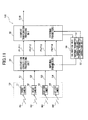
- FIG. 11 is a block diagram showing a configuration of an image calibration device 100 of a second embodiment of the present invention.
- the calibration device 100 illustrated therein is different from the calibration device 100 in Embodiment 1 shown in FIG. 1 in a point that the internal parameter correction unit 51 of the calibration unit 50 performs correction to adjust the internal parameters M so that images of two mutually parallel lines and an image corresponding to one line orthogonal to the two mutually parallel lines in each of viewpoint-transformed partial images in a viewpoint-transformed composite image Q can extend linearly, the viewpoint-transformed composite image Q being subjected to viewpoint transformation processing based on the four distortion-corrected images P1 to P4 (distortion-corrected images obtained by distortion correction based on the internal parameters (default internal parameters) before being corrected).
- the other configuration of the calibration device 100 is the same as that of the calibration device 100 in Embodiment 1, and thus a description thereof will be omitted.
- target images for adjusting the linearity of images of lines of the calibration index 20 are the distortion-corrected images P1 to P4 (distortion-corrected images obtained by distortion correction using the default internal parameters, see FIG. 6 ).
- target images are the four viewpoint-transformed partial images Q21 to Q24 forming a viewpoint-transformed composite image Q20 (the viewpoint-transformed composite image obtained by performing the viewpoint transformation processing using the default external parameters on the four distortion-corrected images P1 to P4 obtained by the distortion correction using the default internal parameters, see FIG. 12 ).
- the internal parameter correction unit 51 performs a correction to adjust a corresponding one of the internal parameters M so that images corresponding to mutually parallel lines and an image corresponding to one line orthogonal to the mutually parallel lines can extend linearly, the images being included in the corresponding one of the viewpoint-transformed partial images Q21 to Q24. Then, the internal parameter correction unit 51 feeds back the corrected internal parameter M to the distortion correction processing unit 30.
- the distortion correction processing unit 30 performs a distortion correction on a corresponding one of the peripheral area images S1 to S4 based on the corrected internal parameter M.
- distortion-corrected images P11 to P 14 can consequently be obtained as in the calibration device 100 in Embodiment 1.
- the distortion-corrected images P11 to P14 are inputted in the viewpoint transformation processing unit 40, and then the viewpoint transformation processing unit 40 performs the viewpoint transformation processing on the inputted distortion-corrected images P11 to P14 by using the default external parameters N.
- a new viewpoint-transformed composite image (hereinafter, referred to as a viewpoint-transformed composite image Q0) is consequently obtained, the viewpoint-transformed composite image Q0 being substantially the same as the new viewpoint-transformed composite image Q0 (see FIG. 8 ) obtained by the calibration device 100 in Embodiment 1.
- the external parameter correction unit 52 performs correction to adjust the external parameters N according to the same operation as that by the external parameter correction unit 52 in the calibration device 100 in Embodiment 1 so that the viewpoint-transformed composite image Q0 can satisfy the conditions (1-1) to (1-4), the conditions (3-1) to (3-4), the conditions (2-1) to (2-9), and the conditions (4-1) to (4-4).
- the viewpoint transformation processing unit 40 repeats a computation by using the corrected external parameters N, and thereby the viewpoint-transformed composite image Q10 shown in FIG. 9 is obtained.
- the image calibration device 100 in Embodiment 2 can also provide the same effect as that of the image calibration device 100 in Embodiment 1.
- the calibration device 100 in Embodiment 2 corrects the internal parameters M for the viewpoint-transformed composite image Q so that images of lines therein can form straight lines
- the calibration device 100 in Embodiment 1 corrects the internal parameters M for each of the distortion-corrected images P so that the images of the lines therein can form straight lines.
- the accuracy reliability is higher in correcting each internal parameter M so that the images of the lines in the distortion-corrected images P can form straight lines than in the case of correcting each internal parameter M so that the images of the lines in the viewpoint-transformed composite image Q can form straight lines.
- the image calibration device 100 in Embodiment 1 can provide calibration having higher reliability on the accuracy than the image calibration device 100 in Embodiment 2.
- the calibration index 20 is constituted of the four mutually parallel horizontal lines H1 to H4 (the lines extending in the width direction of the vehicle 200) and the two mutually parallel vertical lines V1 and V2 (the lines extending in the front-rear direction of the vehicle) all of which are shown in FIG. 3 , and the two outermost horizontal lines H1 and H4 and the two vertical lines V1 and V2 are located outside the vehicle 200.
- the image calibration device according to the present invention is not limited to those in these embodiments.
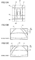
- an image calibration device shown in FIG. 13A , one shown in FIG. 14A , and the like can also be applied thereto.
- the image calibration device only has to be one: in which each of the peripheral area images S1 to S4 taken by a corresponding one of the cameras 10 includes at least images corresponding to two mutually parallel lines and an image corresponding to one line orthogonal to each of the two lines; and in which among the lines included in the calibration index 20, at least one line located within a shooting range of one of the cameras 10 and at least one line located within a shooting range of a different one of the cameras 10 are formed to be located on a straight line.
- a calibration index in a form of omitting one or both of the horizontal line H2 and the horizontal line H3 can form the image calibration device according to the present invention. However, this depends on an installation state (a front-rear direction location in the front-rear direction of the vehicle or a direction of an optical axis) of the right-side camera 13 or the left-side camera 14.
- the calibration index 20 in FIG. 13A includes at least: a horizontal line (a first line) H1, a horizontal line (a second line) H4, a horizontal line (a sixth line) H3 (or a horizontal line H2 (a fifth line) instead of the horizontal line H3 (the sixth line)), a vertical line (a third line) V1, and a vertical line (a fourth line) V2 all of which are straight lines, the horizontal line H1 being placed in front of the vehicle 200 and extending in the vehicle width direction, the horizontal line H4 being placed behind the vehicle 200 and extending in the vehicle width direction, the horizontal line H3 (or the horizontal line H2) being placed between the horizontal line H1 and the horizontal line H4 and extending in the vehicle width direction, the vertical line V1 and the vertical line V2 being placed at both sides of the vehicle 200 and extending in the front-rear direction of the vehicle 200.
- a distance between the mutually parallel lines H1 and H4 a distance between the mutually parallel lines H1 and H3, and a distance between the mutually parallel lines V1 and V2 are also known as in the aforementioned embodiments.
- the same operation and effect as those of the image calibration device 100 including the calibration index 20 shown in FIG. 3 can be obtained in the following manner. Specifically, processing (ensuring the linearity (correcting the internal parameters M in distortion correction) of the image H1 of the horizontal line H1, ensuring the parallelism with the different horizontal lines H3, H4 and the like, and ensuring the distances or the like between the vertical lines V1 and V2 and between the horizontal line H I and the different horizontal lines H3 and H4 (correcting the external parameters N in the viewpoint transformation processing)) which should be performed on the image H1 of the horizontal line H1 in the calibration index 20 shown in FIG.
- the processing which should be performed on the image H2 of the horizontal line H2 is ensuring the linearity (correcting the internal parameters M in the distortion correction) of the image H2 of the horizontal line H2, ensuring the parallelism with the different horizontal lines H3, H4 and the like, and ensuring the distances or the like between the vertical lines V1 1 and V2 and between the horizontal line H2 and the different horizontal lines H3 and H4 (correcting the external parameters N in the viewpoint transformation processing).
- the peripheral area image S3 taken by the right-side camera 13 corresponding to FIG. 4C is one as shown in 11IG. 13B
- the peripheral area image S3 taken by the left-side camera 14 corresponding to FIG. 4D is one as shown in FIG. 13C .
- the calibration index 20 in FIG. 14A includes at least a horizontal line (a first line) H1, a horizontal line (a second line) H4, a vertical line (a third line) V1, and a vertical line (a fourth line) V2 all of which are straight lines, the horizontal line H1 being placed in front of the vehicle 200 and extending in the vehicle width direction, the horizontal line H4 being placed behind the vehicle 200 and extending in the vehicle width direction, the vertical line V1 and the vertical line V2 being placed at both sides of the vehicle 200 and extending in the front-rear direction of the vehicle 200.
- the same operation and effect as those of the image calibration device 100 including the calibration index 20 shown in FIG. 13A can be obtained in the following manner. Specifically, the processing (ensuring the linearity (correcting the internal parameters M in distortion correction) of the image H1 of the horizontal line H1, ensuring the parallelism with the different horizontal line H4 and the like, and ensuring the distances or the like between the vertical lines V1 and V2 and between the horizontal line H1 and the different horizontal line H4 (correcting the external parameters N in the viewpoint transformation processing)) which should be performed on the image H1 of the horizontal line H1 in the calibration index 20 shown in FIG.
- the processing ensuring the linearity (correcting the internal parameters M in distortion correction) of the image H1 of the horizontal line H1, ensuring the parallelism with the different horizontal line H4 and the like, and ensuring the distances or the like between the vertical lines V1 and V2 and between the horizontal line H1 and the different horizontal line H4 (correcting the external parameters N in the viewpoint transformation processing) which should be performed on the image H1 of
- the processing which should be performed on the image H3 of the horizontal line H3 is ensuring the linearity (correcting the internal parameters M in the distortion correction) of the image H3 of the horizontal line H3, ensuring the parallelism with the different horizontal line H4 and the like, and ensuring the distances or the like between the vertical lines V1 and V2 and between the horizontal line H3 and the different horizontal line H4 (correcting the external parameters N in the viewpoint transformation processing).
- the peripheral area image S3 taken by the right-side camera 13 corresponding to FIG 4C is one as shown in FIG. 14B
- the peripheral area image S3 taken by the left-side camera 14 corresponding to FIG. 4D is one as shown in FIG. 14C .
- the images H1 and H4 of the horizontal lines H1 and H4 shown in the peripheral area images S3 and S4 are shorter than the images H2 and H3 of the horizontal lines H2 and H3 shown in the peripheral area images S3 and S4 shown in FIG. 4C and FIG. 4D .
- the accuracy of the correction of the internal parameters M made by ensuring the linearity is higher in the calibration device 100 using the calibration index 20 shown in FIG. 3 .
- the aforementioned calibration device 100 in each embodiment has been described as that in an embodiment of the image calibration device according to the present invention, and the operation of the calibration device 100 can be regarded as that in an embodiment of an image calibration method according to the present invention.
Landscapes
- Engineering & Computer Science (AREA)
- Multimedia (AREA)
- Signal Processing (AREA)
- Physics & Mathematics (AREA)
- Theoretical Computer Science (AREA)
- General Physics & Mathematics (AREA)
- General Health & Medical Sciences (AREA)
- Health & Medical Sciences (AREA)
- Biomedical Technology (AREA)
- Computer Vision & Pattern Recognition (AREA)
- Closed-Circuit Television Systems (AREA)
- Image Processing (AREA)
- Testing, Inspecting, Measuring Of Stereoscopic Televisions And Televisions (AREA)
Abstract
Description
- The present invention relates to an image calibration method and an image calibration device, and particularly relates to improvement of processing of transforming images around a vehicle taken by on-vehicle cameras into a single viewpoint-transformed composite image.
- There is a technique to improve visibility at the time when the vehicle moves backward. In the technique, by displaying an image behind a vehicle taken by an on-vehicle camera on an on-vehicle monitor, a state just close to a place behind a vehicle which is a blind spot for the driver is observed as an image displayed on the on-vehicle monitor.
- For displaying such an image of the on-vehicle camera, there is a technique for calibrating a state of attachment of the on-vehicle camera to the vehicle. For the calibration, a calibration index is provided behind the vehicle, and the driver views an image of the calibration index displayed on the on-vehicle monitor, and thereby simultaneously adjusts the state of attachment of the on-vehicle camera so that the image of the calibration index can be appropriately displayed.
- In addition, there is a technique to appropriately calibrate an image displayed on the on-vehicle monitor by performing certain computation on the image obtained using the on-vehicle camera based on the image of the calibration index (Patent Document 1).
- Moreover, there is another technique to be performed in the following manner. Multiple on-vehicle cameras take images of places all around the vehicle, multiple images obtained by the on-vehicle cameras are transformed into such images (bird's-eye view images) as being looked down from directly above the vehicle, and mapping is performed while relative locations of the images are adjusted. Then, a single viewpoint-transformed composite image is obtained (see Patent Document 2).
- The above cases require accurate positioning of two adjacent images relative to each other, thus requiring highly accurate calibration.
-
- PATENT DOCUMENT I: Japanese Patent Application Publication No.
2001-245326 - PATENT DOCUMENT 2: International Patent Application Publication No.
00/07373 - However, in the conventional calibration methods, a relative positional relationship between the calibration index and the vehicle needs to be set strictly. The calibration index needs to be placed accurately with respect to the vehicle after the vehicle is arranged, or the vehicle needs to be arranged accurately with respect to the vehicle after the calibration index is placed.
- In this respect, vehicle manufacturing line facility is improved at high costs, and thus is devised to improve the accuracy of positioning between the vehicle and the calibration index. Further, in a case where the calibration is again performed in a maintenance department of a sales and service company after the on-vehicle camera is shipped from a manufacturing site (in a case of repairing or in a case of attaching the on-vehicle camera or the like to the vehicle after shipping), the calibration index needs to be placed accurately every time the calibration is performed. Thus, further labor is required.
- The present invention has been made in view of the above circumstances. An object of the present invention is to provide a calibration method and an image calibration device which are capable of alleviating the degree of strictness required for a relative positional relationship between a calibration index placed on a road surface and a vehicle arranged on the road surface.
- The image calibration method and an image calibration device according to the present invention alleviate the degree of strictness required for the relative positional relationship between the calibration index placed on the road surface and the vehicle arranged on the road surface in the following manner. Specifically, among multiple lines provided as a calibration index on the road surface, multiple on-vehicle cameras respectively take images of at least two lines and at least one line orthogonal to the two parallel lines which are mutually parallel and a distance between which is known, Distortion correction is performed on the obtained images by using default internal parameters. Correction of adjusting the internal parameters is performed so that each of images of lines in the calibration index in the thus obtained distortion-corrected images (or a viewpoint-transformed composite image to be described later) by the distortion correction can form a straight line. New distortion-corrected images obtained by the corrected internal parameters are transformed into a single viewpoint-transformed composite image by using default external parameters. The external parameters are corrected so that, like the lines in the actual calibration index: images of some of the lines in the calibration index in the viewpoint-transformed composite image can be parallel to each other; images of some of the lines can be orthogonal to each other; a distance between the parallel lines can coincide with that in the actual calibration index; and the same line (arranged on a straight line) in mutually different images which corresponds to one of the lines in the calibration index can be located on a straight line.
- That is, a first image calibration method of the present invention is an image calibration method including taking peripheral area images of peripheral areas of a vehicle respectively with multiple cameras installed on the vehicle, the peripheral areas including a calibration index provided in advance on a road surface on which the vehicle is arranged, performing distortion correction on the peripheral area images respectively taken by the cameras on the basis of internal parameters according to optical characteristics of the cameras (for example, deviation between an optical axis of an image sensor of an on-vehicle camera and an optical axis of a lens, distortion (aberration or the like) of an image formed by a lens (an image imaged by an image sensor), or the like), performing viewpoint transformation processing on multiple distortion-corrected images obtained by the distortion correction on the basis of external parameters according to states of attachment of the cameras to the vehicle (the relative positional relationship of the vehicle (three-dimensional space coordinate position), and posture (an angle of an optical axis around each axis in three dimensions)), the viewpoint transformation processing being performed so that the multiple distortion-corrected images can be processed into a single viewpoint-transformed composite image obtained when the vehicle is looked down from above the vehicle (for example, a bird's-eye view image as being looked vertically down from a position above the vehicle), and calibrating the viewpoint-transformed composite image by adjusting the external parameters on the basis of an image of the calibration index in the viewpoint-transformed composite image, in the viewpoint transformation processing. The image calibration method is characterized as follows. The calibration index includes at least two lines which are mutually parallel and a distance between which is known and at least one line orthogonal to each of the two lines, and is formed so that each of the peripheral area images can include at least images corresponding to the two mutually parallel lines and an image corresponding to the one line orthogonal to each of the two lines and so that among the lines included in the calibration index, at least one line located in a shooting range of one of the cameras and at least one line located in a shooting range of a different one of the cameras can be located on a straight line. For each of the multiple distortion-corrected images, correction of adjusting the internal parameters is performed so that images corresponding to the two mutually parallel lines and an image corresponding to the one orthogonal line included in the distortion-corrected image can extend linearly. A new viewpoint-transformed composite image is obtained by using new distortion-corrected images obtained by using the corrected internal parameters. The correction of adjusting the external parameters is performed so that the new viewpoint-transformed composite image thus obtained can satisfy the following conditions (1) to (4):
- (1) the images corresponding to the two mutually parallel lines are mutually parallel;
- (2) a distance between the images corresponding to the two mutually parallel lines is the known distance between the lines in the calibration index;
- (3) the image corresponding to the one orthogonal line is orthogonal to the images corresponding to the two parallel lines; and
- (4) images corresponding to the line located on the straight line in the calibration index are located on a straight line.
- However, the calibration index in the first image calibration method of the present invention is not limited to the calibration index in this mode, and only has to be one provided in such a manner that each vehicle-periphery image includes at least images corresponding to at least two mutually parallel lines and an image corresponding to each of the two lines.
- With the thus configured first image calibration method according to the present invention, the multiple cameras installed on the vehicle respectively take the multiple peripheral area images of the peripheral areas of the vehicle, the peripheral area image including the calibration index provided in advance on the road surface on which the vehicle is arranged. The distortion correction is performed on the peripheral area images respectively taken by the cameras, on the basis of the default internal parameters. The viewpoint transformation processing is performed on the multiple distortion-corrected images obtained by the distortion correction on the basis of the external parameters so that the multiple distortion-corrected images can be processed into the single viewpoint-transformed composite image. In the viewpoint transformation processing, the viewpoint-transformed composite image is calibrated by adjusting the external parameters on the basis of the images of the calibration index in the viewpoint-transformed composite image.
- Meanwhile, distortion-corrected images reflect the internal parameters. In a conventional distortion correction, a default value (a common value in defiance of individual differences) which is a design value has been used as each of the internal parameters.
- However, in the first image calibration method of the present invention, the internal parameters are corrected for each of the distortion-corrected images obtained by using the internal parameters of default values, so that each image of the line in the calibration index in the distortion-corrected image can form the straight line. Thus, it is possible to perform distortion correction appropriate for variation in the optical characteristics of the individual cameras and the individual differences.
- Further, a viewpoint-transformed composite image based on the default external parameters is generated by using new distortion-corrected images (each image of the line in the calibration index forms the straight line) obtained based on the internal parameters thus corrected. Since the viewpoint-transformed composite image has the high accuracy distortion corrected images from which the viewpoint-transformed composite image is generated, and thus the viewpoint-transformed composite image necessarily has high accuracy.
- Still further, the external parameters are corrected so that the viewpoint-transformed composite image can satisfy the aforementioned four conditions (1) to (4), and thereby a viewpoint-transformed composite image having further higher accuracy can be obtained.
- Moreover, the aforementioned four conditions (1) to (4) do not depend on the relative positional relationship between the vehicle and the calibration index, and defines by nature the relationship (the parallelism, the orthogonality, the distance between the lines, and the linearity) only among the images of the lines in the viewpoint-transformed composite image. Thus, the strictness of the position of the vehicle or the posture (the direction) of the vehicle with respect to the calibration index at the time of arranging the vehicle with respect to the calibration index is not required.
- That is, the relative positional relationship between the calibration index placed on the road surface and the vehicle arranged on the road surface only has to have accuracy (to a degree of practical level of deviation) of the position and the posture of the vehicle obtained in an ordinary operation of parking in a parking frame in a general parking lot or the like. Thus, the degree of strictness required for the relative positional relationship can be alleviated.
- This means that even if the vehicle is of a different type (the size or shape of the vehicle), the calibration index common thereto can be used without any modification. Thus, a calibration index dedicated for the type of the vehicle does not have to be prepared and to be placed every time calibration is performed, and labor and time of the work can be considerably reduced.
- Note that in the first image calibration method of the present invention, whether or not the images corresponding to the two mutually parallel lines in each distortion-corrected image and the image corresponding to the one line orthogonal to the two lines extend linearly can be determined in the following manner. Specifically, parts of each image are made thin lines by an image processing technique, for example. Then, if differential values (inclinations) of each line at appropriate intervals approximately fall within a certain range, the line can be determined as a straight line.
- In the first image calibration method of the present invention, the internal parameters are corrected for the distortion-corrected images so that each image of the corresponding line can form a straight line. In contrast in a second image calibration method of the present invention to be described later, the internal parameters are corrected for the viewpoint-transformed composite image so that the image of the corresponding line can form a straight line.
- Note that it can be said that a longer image of a line results in higher accuracy reliability in correcting the image of the line to obtain a straight line.
- In this respect, since the images of the lines in each distortion-corrected image taken by the corresponding camera are longer than the images of the lines in the viewpoint-transformed composite image, the accuracy reliability is higher in correcting each internal parameter so that the images of the lines in the distortion-corrected image can form the straight lines than in the case of correcting each internal parameter so that the images of the lines in the viewpoint-transformed composite image can form the straight lines.
- Thus, the first image calibration method of the present invention can provide calibration having higher accuracy reliability than the second image calibration method of the present invention to be described later.
- Further, each image of the corresponding line in the distortion-corrected image for the camera has more pixels corresponding to the image than an image of the line in the corresponding image in the viewpoint-transformed composite image, regardless of whether the image in the distortion-corrected image is longer or not. Thus, correcting the accuracy reliability is higher in correcting each internal parameter so that the image of the line in the distortion-corrected image can form a straight line than in the case of correcting the internal parameter so that the image of the line in the viewpoint-transformed composite image can form a straight line.
- Also learned from this, the first image calibration method of the present invention can provide calibration having higher accuracy reliability than the second image calibration method of the present invention to be described later.
- Meanwhile, there is a case where the internal parameters for simultaneously changing images of all the lines into straight lines do not necessarily exist. In such a case, what is required is to correct the internal parameters by comprehensively evaluate (to obtain such a state that the linearity is ensured in the best balance as a whole) the linearity of the images of all the lines.
- For the new viewpoint-transformed composite image generated based on the new distortion-corrected images in a state after the internal parameters are corrected, that is, a state in which the images of the lines in the calibration index extend linearly, the external parameters are corrected so that the images corresponding to the mutually parallel lines in the calibration index can be mutually parallel in the viewpoint-transformed composite image, so that the distance between the images corresponding to the mutually parallel lines in the viewpoint-transformed composite image can be the known distance between the lines in the calibration index, so that the images corresponding to the mutually orthogonal lines in the calibration index can be mutually orthogonal in the viewpoint-transformed composite image, and so that the images corresponding to the line located on a straight line in the calibration index can be located on a straight line. Whether or not the images in the viewpoint-transformed composite image are parallel can be determined based on whether or not inclinations (differential values) of the images (approximately linear portions) corresponding to the lines coincide with each other. In addition, whether or not the images are orthogonal to each other can be determined based on whether or not a value of the product of the inclinations of the images corresponding to the lines is "-1" (when corresponding portions of the images are expressed in vectors, based on whether or not a value of the inner product thereof is "0").
- Note that there is also a case where the external parameters cannot be adjusted to those by which corresponding images become in a completely parallel state (in a state where inclination values are exactly identical) or in a completely orthogonal state (a value of the product of inclinations is exactly "-1"). In such a case, what is required is to adjust the external parameters by comprehensively evaluate (to obtain such a state that the parallelism and the linearity is ensured in the best balance as a whole) the aforementioned parallelism and the linearity.
- Moreover, whether or not the images in the viewpoint-transformed composite image corresponding to the line located on a straight line in the calibration index are located on the straight line can be determined based on whether or not the inclinations of the images coincide with an intercept x (or an intercept y) at the time when the lines are expressed in the two-dimensional Cartesian system defined by the x axis and the y axis (orthogonal to the x axis).
- As described above, with the first image calibration method according to the present invention, the internal parameters are adjusted so that the images in the distortion-corrected images corresponding to the calibration index can extend linearly. Thereby, it is possible to achieve higher accuracy calibration than the conventional calibration in which the fixed internal parameter is used and the external parameter is adjusted.
- Moreover, with the first image calibration method according to the present invention, the calibration index is formed by the lines in comparison with the conventional calibration method performed only based on points. Thus, the accuracy can be improved more than in the conventional calibration in which distortions between the points are not considered.
- In addition, the at least two lines which are parallel and the distance between which is known and the at least one line orthogonal to these two lines are applied to the lines described above, and thereby the external parameters are adjusted based on the parallelism degree and the orthogonality degree of the images in the viewpoint-transformed composite image, based on the distance between the images (the lines), and so that the images corresponding to the lines located on a straight line which are overlappingly shown in the multiple images can be located on a straight line. Thus, highly accurate calibration can be performed all over the viewpoint-transformed composite image.
- In the first image calibration method of the present invention, the internal parameters are corrected based on the linearity of the images in each distortion-corrected image. In contrast, in the second image calibration method of the present invention, the internal parameters are corrected based on the linearity of the images of the lines in the calibration index in the viewpoint-transformed composite image, instead of the distortion-corrected image.
- That is, the second image calibration method of the present invention is an image calibration method including: taking peripheral area images of peripheral areas of a vehicle respectively with multiple cameras installed on the vehicle, the peripheral areas including a calibration index provided in advance on a road surface on which the vehicle is arranged, performing distortion correction on the peripheral area images respectively taken by the cameras on the basis of internal parameters according to optical characteristics of the cameras, performing viewpoint transformation processing on multiple distortion-corrected images obtained by the distortion correction on the basis of external parameters according to states of attachment of the cameras to the vehicle, the viewpoint transformation processing being performed so that the multiple distortion-corrected images can be processed into a single viewpoint-transformed composite image obtained when the vehicle is looked down from above the vehicle, and calibrating the viewpoint-transformed composite image by adjusting the external parameters on the basis of an image of the calibration index in the viewpoint-transformed composite image, in the viewpoint transformation processing. The image calibration method is characterized as follows. The calibration index includes at least two lines which are mutually parallel and a distance between which is known and at least one line orthogonal to each of the two lines, and is formed so that each of the peripheral area images can include at least images corresponding to the two mutually parallel lines and an image corresponding to the one line orthogonal to each of the two lines and so that among the lines included in the calibration index, at least one line located in a shooting range of one of the cameras and at least one line located in a shooting range of a different one of the cameras can be located on a straight line. For the viewpoint-transformed composite image, correction of adjusting the internal parameters is performed so that images corresponding to the two mutually parallel lines and an image corresponding to the one orthogonal line included in the distortion-corrected image can extend linearly. The viewpoint-transformed composite image is obtained by using new distortion-corrected images obtained by using the corrected internal parameters. The correction of adjusting the external parameters is performed so that the new viewpoint-transformed composite image thus obtained can satisfy the following conditions (1) to (4):
- (1) the images corresponding to the two mutually parallel lines are mutually parallel;
- (2) a distance between the images corresponding to the two mutually parallel lines is the known distance between the lines in the calibration index;
- (3) the image corresponding to the one orthogonal line is orthogonal to the images corresponding to the two parallel lines; and
- (4) images corresponding to the line located on the straight line in the calibration index are located on a straight line.
- However, as has been described about the first image calibration method of the present invention, the first image calibration method in which the internal parameters are corrected based on the linearity of the images in each distortion-corrected image can have higher image linearity accuracy than the second image calibration method in which the internal parameters are corrected based on the linearity of the images in the viewpoint-transformed composite image, and thus can have enhanced accuracy of the internal parameters.
- A first image calibration device of the present invention is a device for implementing the first image calibration method of the present invention. The image calibration device includes a calibration index provided in advance on a road surface on which a vehicle is arranged, multiple cameras installed on the vehicle which take peripheral area images of peripheral areas of the vehicle, the peripheral areas including the calibration index, a distortion correction device for performing distortion correction on the peripheral area images respectively taken by the cameras, on the basis of internal parameters according to optical characteristics of the cameras, a viewpoint transformation processing device for performing viewpoint transformation processing on multiple distortion-corrected images obtained by the distortion correction on the basis of external parameters according to states of attachment of the cameras to the vehicle, the viewpoint transformation processing being performed so that the multiple distortion-corrected images can be processed into a single viewpoint-transformed composite image obtained when being looked down from above the vehicle, and a calibration device for calibrating the viewpoint-transformed composite image by adjusting the external parameters on the basis of images of the calibration index in the viewpoint-transformed composite image, in the viewpoint transformation processing performed by the viewpoint transformation processing device. The image calibration device is characterized as follows. The calibration index includes at least two lines which are mutually parallel and a distance between which is known and at least one line orthogonal to each of the two lines, and is formed so that each of the vehicle-periphery images can include at least images corresponding to the two mutually parallel lines and an image corresponding to the one line orthogonal to each of the two lines, and so that among the lines included in the calibration index, at least one line located in a shooting range of one of the cameras and at least one line located in a shooting range of a different one of the cameras can be located on a straight line. The calibration device includes an internal parameter correction device and an external parameter correction device. The internal parameter correction device performs correction of adjusting the internal parameters for the viewpoint-transformed composite image so that images corresponding to the two mutually parallel lines and an image corresponding to the one orthogonal line included in the viewpoint-transformed composite image can extend linearly. When a new viewpoint-transformed composite image is obtained by using new distortion-corrected images obtained by the distortion correction device by using the corrected internal parameters, the external parameter correction device performs correction of adjusting the external parameters so that the new viewpoint-transformed composite image thus obtained can satisfy the following conditions (1) to (4):
- (1) the images corresponding to the two mutually parallel lines are mutually parallel;
- (2) a distance between the images corresponding to the two mutually parallel lines is the known distance between the lines in the calibration index;
- (3) the image corresponding to the one orthogonal line is orthogonal to the images corresponding to the two parallel lines; and
- (4) images corresponding to the line located on the straight line in the calibration index are located on a straight line.
- In addition, for each of the multiple distortion-corrected images, the internal parameter correction device of the calibration device performs the correction of adjusting the internal parameter so that the images corresponding to the two mutually parallel lines included in the distortion-corrected image and the image corresponding to the one orthogonal line can extend linearly.
- Further, when obtaining the new viewpoint-transformed composite image by using the new distortion-corrected images obtained by the distortion correction device by using the corrected internal parameters, the external parameter correction device of the calibration device performs correction of adjusting the external parameters so that the new viewpoint-transformed composite image thus obtained can satisfy the aforementioned conditions (1) to (4).
- As described above, with the first image calibration device according to the present invention, the internal parameters are adjusted so that the images in the distortion-corrected images corresponding to the calibration index can extend linearly. Thereby, it is possible to achieve higher accuracy calibration than the conventional calibration in which the fixed internal parameter is used and the external parameter is adjusted.
- Moreover, with the first image calibration device according to the present invention, the calibration index is formed by the lines in comparison with the conventional calibration device using only points. Thus, it is possible to improve the accuracy than in the conventional calibration in which distortion between the points is not considered.
- In addition, the at least two lines which are parallel and the distance between which is known and the at least one line orthogonal to these two lines are applied to the lines described above, and thereby the external parameters are adjusted based on the parallelism degree and the orthogonality degree of the images in the viewpoint-transformed composite image, based on the distance between the images (the lines), and so that the images corresponding to the lines located on a straight line which are overlappingly shown in the multiple images can be located on a straight line. Thus, highly accurate calibration can be performed all over the viewpoint-transformed composite image.
- The first image calibration device of the present invention corrects the internal parameters for the distortion-corrected images so that each image of the corresponding line can form a straight line. In contrast, a second image calibration device of the present invention to be described later corrects the internal parameters for the viewpoint-transformed composite image so that the image of the corresponding line can form a straight line.
- Note that it can be said that a longer image of a line results in higher accuracy reliability in correcting the image of the line to obtain a straight line.
- In this respect, since the images of the lines in each distortion-corrected image are longer than the images of the lines in the viewpoint-transformed composite image, the accuracy reliability is higher in correcting each internal parameter so that the images of the lines in the distortion-corrected image can form the straight lines than in the case of correcting each internal parameter so that the images of the lines in the viewpoint-transformed composite image can form the straight lines.
- Thus, the first image calibration device of the present invention can provide calibration having higher accuracy reliability than the second image calibration device of the present invention to be described later.
- The first image calibration device of the present invention corrects the internal parameters based on the linearity of the images in each distortion-corrected image. In contrast, the second image calibration device of the present invention corrects the internal parameters based on the linearity of the images of the lines in the calibration index in the viewpoint-transformed composite image, instead of the distortion-corrected image.
- Specifically, the second image calibration device of the present invention is an image calibration device including a calibration index provided in advance on a road surface on which a vehicle is arranged, multiple cameras installed on the vehicle which take peripheral area images of peripheral areas of the vehicle, the peripheral areas including the calibration index, a distortion correction device for performing distortion correction on the peripheral area images respectively taken by the cameras on the basis of internal parameters according to optical characteristics of the cameras, a viewpoint transformation processing device for performing viewpoint transformation processing on multiple distortion-corrected images obtained by the distortion correction on the basis of external parameters according to states of attachment of the cameras to the vehicle, the viewpoint transformation processing being performed so that the multiple distortion-corrected images can be processed into a single viewpoint-transformed composite image obtained when being looked down from above the vehicle, and a calibration device for calibrating the viewpoint-transformed composite image by adjusting the external parameters on the basis of images of the calibration index in the viewpoint-transformed composite image, in the viewpoint transformation processing performed by the viewpoint transformation processing device. The image calibration device is characterized as follows. The calibration index includes at least two lines which are mutually parallel and a distance between which is known and at least one line orthogonal to each of the two lines, and is formed so that each of the peripheral area images can include at least images corresponding to the two mutually parallel lines and an image corresponding to the one line orthogonal to each of the two lines, and so that among the lines included in the calibration index, at least one line located in a shooting range of one of the cameras and at least one line located in a shooting range of a different one of the cameras can be located on a straight line. The calibration device includes an internal parameter correction device and an external parameter correction device. The internal parameter correction device performs correction of adjusting the internal parameters for the viewpoint-transformed composite image so that images corresponding to the two mutually parallel lines and an image corresponding to the one orthogonal line included in the viewpoint-transformed composite image can extend linearly. When a new viewpoint-transformed composite image is obtained by using new distortion-corrected images obtained by the distortion correction device by using the corrected internal parameters, the external parameter correction device performs correction of adjusting the external parameters so that the new viewpoint-transformed composite image thus obtained can satisfy the following conditions (1) to (4):
- (1) the images corresponding to the two mutually parallel lines are mutually parallel;
- (2) a distance between the images corresponding to the two mutually parallel lines is the known distance between the lines in the calibration index;
- (3) the image corresponding to the one orthogonal line is orthogonal to the images corresponding to the two parallel lines; and
- (4) images corresponding to the line located on the straight line in the calibration index are located on a straight line.
- In addition, the internal parameter correction device of the calibration device performs the correction of adjusting the internal parameters for the viewpoint-transformed composite image so that the images corresponding to the two mutually parallel lines included in the viewpoint-transformed composite image and the image corresponding to the one orthogonal line can extend linearly.
- Further, when obtaining the new viewpoint-transformed composite image by using the new distortion-corrected images obtained by the distortion correction device by using the corrected internal parameters, the external parameter correction device of the calibration device performs the correction of adjusting the external parameters so that the new viewpoint-transformed composite image thus obtained can satisfy the aforementioned conditions (1) to (4).
- The thus configured second image calibration device according to the present invention can provide the same operation and effect as those in the aforementioned first image calibration device of the present invention.
- However, as has been described about the first image calibration device of the present invention, the first image calibration device which corrects the internal parameters based on the linearity of the images in each distortion-corrected image can have higher image linearity accuracy than the second image calibration device which corrects the internal parameters based on the linearity of the images in the viewpoint-transformed composite image, and thus can have enhanced accuracy of the internal parameters.
- With the image calibration method and the image calibration device according to the present invention, it is possible to alleviate the degree of strictness required for a relative positional relationship between a calibration index placed on a road surface and a vehicle arranged on the road surface.
-
- [
FIG. 1] FIG. 1 is a block diagram showing a schematic configuration of an image calibration device according toEmbodiment 1 of the present invention. - [
FIG. 2] FIG. 2 is a schematic diagram showing a vehicle with four cameras mounted thereon. - [
FIG. 3] FIG. 3 is a diagram showing an example of a calibration index. - [
FIG. 4A] FIG. 4A is an image taken by a front camera among peripheral area images obtained by being taken by the cameras. - [
FIG. 4B] FIG. 4B is an image taken by a rear camera among the peripheral area images obtained by being taken by the cameras. - [
FIG. 4C] FIG. 4C is an image taken by a right-side camera among the peripheral area images obtained by being taken by the cameras. - [
FIG. 4D] FIG. 4D is an image taken by a left-side camera among the peripheral area images obtained by being taken by the cameras. - [
FIG. 5] FIG. 5 is a diagram showing an example of a state where the vehicle shown inFIG. 2 is arranged on a road surface on which the calibration index shown inFIG. 3 is formed. - [
FIG. 6A] FIG. 6A is a distortion-corrected image corresponding to the front camera among distortion-corrected images obtained after distortion correction is performed on the peripheral area images by using default internal parameters. - [
FIG. 6B] FIG. 6B is a distortion-corrected image corresponding to the rear camera among the distortion-corrected images obtained after the distortion correction is performed on the peripheral area images by using the default internal parameters. - [
FIG. 6C] FIG. 6C is a distortion-corrected image corresponding to the right-side camera among the distortion-corrected images obtained after the distortion correction is performed on the peripheral area images by using the default internal parameters. - [
FIG. 6D] FIG. 6D is a distortion-corrected image corresponding to the left-side camera among the distortion-corrected images obtained after the distortion correction is performed on the peripheral area images by using the default internal parameters. - [
FIG. 7A] FIG. 7A is a distortion-corrected image corresponding to the front camera among the distortion-corrected images obtained after distortion correction is performed on the peripheral area images by using corrected internal parameters. - [
FIG. 7B] FIG. 7B is a distortion-corrected image corresponding to the rear camera among the distortion-corrected images obtained after the distortion correction is performed on the peripheral area images by using the corrected internal parameters. - [
FIG. 7C] FIG. 7C is a distortion-corrected image corresponding to the right-side camera among the distortion-corrected images obtained after the distortion correction is performed on the peripheral area images by using the corrected internal parameters. - [
FIG. 7D] FIG. 7D is a distortion-corrected image corresponding to the left-side camera among the distortion-corrected images obtained after the distortion correction is performed on the peripheral area images by using the corrected internal parameters. - [
FIG. 8] FIG. 8 is a diagram showing a viewpoint-transformed composite image on which view-point transformation processing is performed in a state where only the internal parameters are corrected and default external parameters are applied. - [
FIG. 9] FIG. 9 is a diagram showing a viewpoint-transformed composite image on which the view-point transformation processing is performed in a state where both the internal parameters and the external parameters are corrected. - [
FIG. 10A] FIG. 10A is a schematic diagram showing a state where the vehicle is arranged in a posture not straightened with respect to the calibration index. - [
FIG. 10B] FIG. 10B is a diagram showing a synthesized bird's-eye view image obtained in the arrangement state inFIG. 10A . - [
FIG. 11] FIG. 11 is a block diagram showing a schematic configuration of an image calibration device according toEmbodiment 2 of the present invention. - [
FIG. 12] FIG. 12 is a diagram showing a viewpoint-transformed composite image on which calibration processing is performed in a state where default internal and external parameters are applied thereto. - [
FIG. 13A] FIG. 13A exemplifies a case (Case 1) of application of a calibration index of a different embodiment, and is a diagram showing an applicable calibration index in the same state ofFIG. 5 . - [
FIG. 13B] FIG. 13B exemplifies the case (Case 1) of application of the calibration index of the different embodiment, and is a peripheral area image shown by a right side mirror in the case of application of the calibration index inFIG. 13A . - [
FIG. 13C] FIG. 13C exemplifies the case (Case 1) of application of the calibration index of the different embodiment, and is a peripheral area image shown by a left side mirror in the case of application of the calibration index inFIG. 13A . - [
FIG. 14A] FIG. 14A exemplifies a case (Case 2) of application of a calibration index of a different embodiment, and is a diagram showing an applicable calibration index in the same state ofFIG. 5 . - [
FIG. 14B] FIG. 14B exemplifies the case (Case 2) of application of the calibration index of the different embodiment, and is a peripheral area image shown by a right side mirror in the case of application of the calibration index inFIG. 13A . - [
FIG. 14C] FIG. 14C exemplifies the case (Case 2) of application of the calibration index of the different embodiment, and is a peripheral area image shown by a left side mirror in the case of application of the calibration index inFIG. 13A . - Hereinafter, embodiments of an image calibration device according to the present invention will be described by referring to the drawings.
-
FIG. 1 is a block diagram showing a configuration of animage calibration device 100 of one embodiment of the present invention. - The
calibration device 100 illustrated therein includes four cameras 10 (a front-portion (front)camera 11, a rear-portion (rear)camera 12, a right-side-portion (right-side)camera 13, and a left-side-portion (left-side) camera 14), a calibration index 20 (seeFIG. 3 ) to be described later drawn in advance on a road surface on which avehicle 200 is arranged (a state where thevehicle 200 is arranged on the road surface on which thecalibration index 20 is placed is shown inFIG. 5 ), a distortion correction processing unit 30 (distortion correction processing device), a viewpoint transformation processing unit 40 (viewpoint transformation processing device), and a calibration unit 50 (calibration device). Thecameras 10 are respectively installed on a front portion, a rear portion, a right-side portion, and a left-side portion of thevehicle 200, and take images of peripheral areas R1, R2, R3, and R4 (seeFIG. 2 ) of thevehicle 200 as peripheral area images S 1 (seeFIG. 4A ), S2 (seeFIG. 4B ), S3 (seeFIG. 4C ), and S4 (seeFIG. 4D ), respectively, the peripheral areas R1, R2, R3, and R4 including part of thevehicle 200 and thecalibration index 20 shown inFIG. 3 . For each of the peripheral area images S (the peripheral area image S1 obtained by taking an image of the peripheral area R1 (in front of the vehicle 200) by thefront camera 11, the peripheral area image S2 obtained by taking an image of the peripheral area R2 (behind the vehicle 200) by therear camera 12, the peripheral area image S3 obtained by taking an image of the peripheral area R3 (in an area on the right side of the vehicle 200) by the right-side camera 13, and the peripheral area image S4 obtained by taking an image of the peripheral area R4 (in an area on the left side of the vehicle 200) by the left-side camera 14), the distortioncorrection processing unit 30 performs distortion correction to remove distortion (such as aberration due to optical systems (such as lenses) included in the cameras 10) by using internal parameters M (an internal parameter M1 of thefront camera 11, an internal parameter M2 of therear camera 12, an internal parameter M3 of the right-side camera 13, and an internal parameter M4 of the left-side camera 14) according to optical characteristics of therespective cameras transformation processing unit 40 performs view-point transformation processing on four distortion-corrected images P (a distortion-corrected image P1 corresponding to the peripheral area image S1, a distortion-corrected image P2 corresponding to the peripheral area image S2, a distortion-corrected image P3 corresponding to the peripheral area image S3, and a distortion-corrected image P4 corresponding to the peripheral area image S4) based on external parameters N (an external parameter N1 for thefront camera 11, an external parameter N2 for therear camera 12, an external parameter N3 for the right-side camera 13, and an external parameter N4 for the left-side camera 14) according to states of attachment of thecameras 10 to thevehicle 200 so that the four distortion-corrected images P can be processed into a single viewpoint-transformed composite image Q0 obtained by looking down thevehicle 200 from above. For the viewpoint transformation processing performed by the viewpoint transformation processing unit, thecalibration unit 50 calibrates the viewpoint-transformed composite image Q0 by adjusting the external parameters N based on an image of thecalibration index 20 in the viewpoint-transformed composite image Q0. - Note that, as shown in
FIG. 3 , for example, thecalibration index 20 includes: a straight first horizontal line (a first line) H1 which is to be located in front of thevehicle 200 in the state where thevehicle 200 is arranged (FIG. 5 ) and extends in a width direction (a vehicle width direction) of thevehicle 200; a straight fourth horizontal line (a second line) H4 which is to be located behind thevehicle 200 and extends in the vehicle width direction; a second horizontal line (a fifth line) H2 and a third horizontal line (a sixth line) H3 which are straight, are to be located between the first horizontal line H1 and the fourth horizontal line H4, and extend in the vehicle width direction; a straight first vertical line (a third line) V1 which is to be located on the right side of thevehicle 200 and extends in a front-rear direction of thevehicle 200; and a straight second vertical line (a fourth line) V2 which is to be located on the left side of thevehicle 200 and extends in the front-rear direction of thevehicle 200. - In addition, the first horizontal line H1, the second horizontal line H2, the third horizontal line H3, and the fourth horizontal line H4 are parallel to each other. Moreover, a distance between the first horizontal line H1 and the second horizontal line H2 is set at a known distance B, a distance between the second horizontal line H2 and the third horizontal line H3 is set at a known distance C, a distance between the third horizontal line H3 and the fourth horizontal line H4 is set at a known distance D, and a distance between the first horizontal line H1 and the fourth horizontal line H4 is set at a known distance E.
- Besides, the first vertical line V1 and the second vertical line V2 are also parallel to each other and orthogonal to the horizontal lines H1, H2, H3, and H4, and a distance between the first
vertical line V 1 and the second vertical line V2 is set at a known distance A. - In addition, the
calibration index 20 is configured such that each of the peripheral area images S1, S2, S3, and S4 includes: ones of images H1, H2, H3, H4, V1, and V2 corresponding to at least two mutually parallel lines (two lines of the lines H1, H2, H3, and H4 or two lines of the lines V1 and V2) (the same reference numerals of the lines are used for reference numerals of the respective images to avoid complicatedness of the description, and the same applies heretofore); and one of the images V1, V2, H1 H2, H3, and H4 corresponding to one (one line of the lines V1 and V2 or one line of the lines H1, H2, H3, and H4) which is orthogonal to each of the two lines. - Specifically, the peripheral
area image S 1 shows: the images V1 and V2 of the two mutually parallel vertical lines V1 and V2 among the lines H1, H2, H3, H4, V1, and V2 of thecalibration index 20; and the image H1 of the one horizontal line H1 orthogonal to each of the two vertical lines V1 and V2 (FIG. 4A ). - Likewise, the peripheral area image S2 shows: the images V1 and V2 of the two mutually parallel vertical lines V1 and V2 among the lines H1, H2, H3, H4, V1, and V2 of the
calibration index 20; and the image H4 of the one horizontal line H4 orthogonal to each of the two vertical lines V1 and V2 (FIG. 4B ). - Likewise, the peripheral area image S3 shows: the images H2 and H3 of the two mutually parallel horizontal lines H2 and H3 among the lines H1, H2, H3, H4, V1, and V2 of the
calibration index 20; and theimage V 1 of the one vertical line V1 orthogonal to each of the two horizontal lines H2 and H3 (FIG. 4C ). - Likewise, the peripheral area image S4 shows: the images H2 and H3 of the two mutually parallel horizontal lines H2 and H3 among the lines H1, H2, H3, H4, V1, and V2 of the
calibration index 20; and the image V2 of the one vertical line V2 orthogonal to each of the two horizontal lines H2 and H3 (FIG. 4D ). - As a premise to satisfy a condition (4) to be described later, each of the peripheral area images S1, S2, S3, and S4 shows one of the images (V1, V2, H2, and H3) of the corresponding line (V1, V2, H2, and H3) which is also shown in a different one of the peripheral area images S1, S2, S3, and S4 and is located on a straight line in the
calibration index 20 in reality. - In other words, the peripheral
area image S 1 shows: the image V1 of theline V 1 which is shown in the different peripheral area images S2 and S3 and is located on a straight line in thecalibration index 20 in reality; and the image V2 of the line V2 which is shown in the different peripheral area images S2 and S4 and is located on a straight line in thecalibration index 20 in reality. - Likewise, the peripheral area image S2 shows: the image V1 of the
line V 1 which is shown in the different peripheralarea images S 1 and S3 and is located on a straight line in thecalibration index 20 in reality; and the image V2 of the line V2 which is shown in the different peripheral area images S1 and S4 and is located on a straight line in thecalibration index 20 in reality. - Furthermore, the peripheral area image S3 shows the image H1, the image H2, the image H3, and the image H4 of the respective line H1, the line H2, the line H3, and the line H4 which are shown in the different peripheral area image S4 and are located on straight lines in the
calibration index 20 in reality. Note that the image H1 of the line H1 shown in the peripheral area image S3 is also shown in the different peripheral area image S1, and the image H4 of the line H4 is also shown in the different peripheral area image S2. - Likewise, the peripheral area image S4 shows the image H1, the image H2, the image H3, and the image H4 of the respective line H1, the line H2, the line H3, and the line H4 which are shown in the different peripheral area image S3 and are located on straight lines in the
calibration index 20 in reality. Note that the image H1 of the line H1 shown in the peripheral area image S4 is also shown in the different peripheral area image S1, and the image H4 of the line H4 is also shown in the different peripheral area image S2. - The
calibration unit 50 includes an internal parameter correction unit 51 (internal parameter correction device) and an external parameter correction unit 52 (external parameter correction device). For each of the four distortion-corrected images P1 to P4, the internalparameter correction unit 51 performs a correction to adjust a corresponding one of the internal parameters M so that images corresponding to two mutually parallel lines and an image corresponding to one line orthogonal to the mutually parallel lines can extend linearly, the images being included in the corresponding one of the distortion-corrected images P1 to P4. When a new viewpoint-transformed composite image Q10 is obtained by using new distortion-corrected images P11, P12, P13, and P14 (P11 denotes a new distortion-corrected image corresponding to the distortion-corrected image P1 based on a corresponding one of the default internal parameters; P12, a new distortion-corrected image corresponding to the distortion-corrected image P2 based on a corresponding one of the default internal parameters M; P13, a new distortion-corrected image corresponding to the distortion-corrected image P3 based on a corresponding one of the default internal parameters M; andP 14, a new distortion-corrected image corresponding to the distortion-corrected image P4 based on a corresponding one of the default internal parameters M) obtained by the distortioncorrection processing unit 30 by using the corrected internal parameters M, the externalparameter correction unit 52 performs correction to adjust the external parameters N so that the new viewpoint-transformed composite image Q10 can satisfy the following conditions (1) to (4). - (1) The images corresponding to the two mutually parallel ones of the lines H1, H2, H3, and H4 or corresponding to the lines V1 and V2 are mutually parallel.
- (2) A distance between images corresponding to the two mutually parallel ones of the lines H1, H2, H3, and H4 or corresponding to the lines V1 and V2 is a corresponding one of the known distances (A, B, C, D, and E) between the two lines in the
calibration index 20. - (3) The image corresponding to the one orthogonal one of the lines V1 and V2 or one of the lines H1, H2, H3, and H4 is orthogonal to the images corresponding to the two parallel ones of the lines H1, H2, H3, and H4 or to the lines V1 and V2.
- (4) Images corresponding to the line located on the straight line in the
calibration index 20 are located on a straight line. - Firstly, the
vehicle 200 shown inFIG. 2 is arranged on the flat road surface on which thecalibration index 20 shown inFIG. 3 is drawn in advance as shown inFIG. 5 , thevehicle 200 having thefront camera 11, therear camera 12, the right-side camera 13, and the left-side camera 14 installed on the front, rear, right, and left portions of thevehicle 200, respectively. - In one state (a direction (a posture) and a location of the
vehicle 200 with respect to the horizontal lines H and the vertical lines V of the calibration index 20) of arrangement of thevehicle 200 with respect to thecalibration index 20, thevehicle 200 may be arranged in a straightened posture (a posture in which the front-rear direction of thevehicle 200 is parallel to the vertical lines V1 and V2 of thecalibration index 20, and the width direction of thevehicle 200 is parallel to the horizontal lines H1, H2, H3, and H4 of the calibration index 20) on the center of thecalibration index 20 as shown inFIG. 5 , but may be arranged in an oblique posture with respect to thecalibration index 20 as shown inFIG. 10A , for example. Likewise, thevehicle 200 may be arranged in a position deviated from the center of thecalibration index 20. - In this embodiment, the description is given below for a case of the arrangement shown in
FIG. 5 . However, even in an arrangement state (for example, the arrangement state inFIG. 10A ) other than this arrangement state, an operation and an effect exerted by the present invention are the same as those in the case of the arrangement state inFIG. 5 . - In the state where the
vehicle 200 is arranged on thecalibration index 20 as shown inFIG. 5 , thecameras calibration device 100 take images of the peripheral areas R1, R2, R3, and R4 including part of thevehicle 200 and part of thecalibration index 20. Thereby, the peripheral area images S 1 (seeFIG. 4A ), S2 (seeFIG. 4B ), S3 (seeFIG. 4C ), and S4 (seeFIG. 4D ) corresponding to the peripheral areas R1, R2, R3, and R4, respectively, are obtained by thecameras - The peripheral area images S1, S2, S3, and S4 obtained by the
cameras - Specifically, the peripheral
area image S 1 shows theimages V 1 and V2 of the mutually parallel vertical lines V1 and V2 in thecalibration index 20 and the image H1 of the one orthogonal horizontal line H1(FIG. 4A ). The peripheral area image S2 shows the images V1 and V2 of the mutually parallel vertical lines V1 and V2 in thecalibration index 20 and the image H4 of the one orthogonal horizontal line H4(FIG. 4B ). The peripheral area image S3 shows the images H2 and H3 of the two mutually parallel horizontal lines H2 and H3 and the image V1 of the one orthogonal vertical line V1 (FIG. 4C ). The peripheral area image S4 shows the images H2 and H3 of the two mutually parallel horizontal lines H2 and H3 and the image V2 of the one orthogonal vertical line V2 (FIG. 4D ). - Meanwhile, it is more preferable that in each image of the peripheral area image S3 taken by the right-
side camera 13 and the peripheral area image S4 taken by the left-side camera 14, thecalibration index 20 should be set so that at least the line H2 and the line H3 can be taken symmetrically or that a default positional relationship between thevehicle 200 and thecalibration index 20 should be set, because both the length of the line H2 and the length of the line H3 can be ensured to be long and the accuracy can be further enhanced in correction performed with ensured linearity to be described later. However, the lines H2 and H3 do not have to be necessarily symmetrical to each other in the corresponding image as illustrated in this embodiment. - The peripheral area images S1 to S4 are inputted in the distortion
correction processing unit 30. The distortioninput processing unit 30 performs the distortion correction on the inputted peripheral area images S1 to S4 by using the default internal parameters M. Thereby, the peripheral area images S1, S2, S3, and S4 are the distortion-corrected images P1 to P4 on which distortions have been corrected to some extent as shown inFIGs. 6A to 6D . - Meanwhile, each of the default internal parameters M is a design value set uniformly in defiance of individual differences of the optical characteristics of the
cameras 10. Thus, if the optical characteristics of thecameras 10 were ideal ones exactly identical to the design value, the distortion correction using the default internal parameters M would result in the distortion-corrected images P1, P2, P3, and P4 on which distortions thereof are completely corrected. - However, the
cameras 10 in reality have the individual differences in the optical characteristics due to a design allowance or the like set with a manufacturing error taken into consideration. - Thus, the internal parameters M used for the distortion correction should be different from each other by nature according to the
individual cameras 10. - However, since the distortion
correction processing unit 30 firstly performs the distortion correction by using the default internal parameters M, the distortions have not been completely corrected in the obtained distortion-corrected images P1, P2, P3, and P4. - Hence, in the
calibration device 100 in this embodiment, the internalparameter correction unit 51 of thecalibration unit 50 corrects the default internal parameters M of the distortioncorrection processing unit 30. - The correction of each internal parameter M performed by the internal
parameter correction unit 51 is processing in which the images H1, H2, H3, H4, V1, and V2 of the lines H1, H2, H3, H4, V1, and V2 in thecalibration index 20 included in each distortion-corrected image S end up with images extending linearly as shown inFIG. 7 by serially changing a value of the internal parameter M by trial and error. - The corrected internal parameters are obtained from the internal parameters M1, M2, M3, and M4 corresponding to the
respective cameras calibration index 20 included in the distortion-corrected image S end up with images extending linearly. - That is, the internal parameters M1 to M4 are internal parameters respectively for the
cameras 11 to 14 having individual differences in optical characteristics. The distortioncorrection processing unit 30 performs the distortion correction by using the internal parameters M1 to M4 for therespective cameras 11 to 14, and thereby the peripheral area images S1, S2, S3, and S4 turn into the distortion-corrected images P11, P12, P13, and P14 on which distortions thereof have been corrected accurately as shown inFIG. 7A, FIG. 7B, FIG. 7C, and FIG. 7D , respectively. - Next, the obtained distortion-corrected images P11 to P14 are inputted in the viewpoint
transformation processing unit 40. The viewpointtransformation processing unit 40 performs the viewpoint transformation processing according to the default external parameters N on the inputted distortion-correctedimages P 11 toP 14 to generate the single viewpoint-transformed composite image Q0 shown inFIG. 8 . - Note that in the viewpoint-transformed composite image Q0 in
FIG. 8 , a portion corresponding to the distortion-corrected image P11 is a viewpoint-transformed partial image Q11, a portion corresponding to the distortion-corrected image P12 is a viewpoint-transformed partial image Q12, a portion corresponding to the distortion-corrected image P13 is a viewpoint-transformed partial image Q13, and a portion corresponding to the distortion-corrected image P14 is a viewpoint-transformed partial image Q14. - At this time, the correction has been completed in each of the distortion-corrected images P11, P12, P13, and P14 so that the images H1, H2, H3, H4, V1, and V2 of the lines H1, H2, H3, H4, V1, and V2 of the
calibration index 20 can have straight line shapes. Thus, the images H1, H2, H3, H4, V1, and V2 of the lines H1, H2, H3, H4, V1, and V2 of thecalibration index 20 in each of the viewpoint-transformed partial images Q11 to Q14 generated based on the distortion-corrected images P11, P12, P13, andP 14 also have straight line shapes. - Nevertheless, the default external parameters N used in the viewpoint transformation processing performed by the viewpoint
transformation processing unit 40 are design values set uniformly in defiance of individual differences of states of the attachment of thecameras 10 with respect to thevehicle 200. Thus, if the states of the attachment of thecameras 10 were ideal ones exactly identical to the design values, the images H1, H2, H3, H4, V1, and V2 of the lines H1, H2, H3, H4, V1, and V2 of thecalibration index 20 in the viewpoint-transformed composite image Q0 obtained by the viewpoint transformation processing using the default external parameters N would be parallel to each other and distances between the images of the lines would coincide with the known values (A, B, C, D, and E), or orthogonal to each other, like the lines H1, H2, H3, H4, V1, and V2 in thecalibration index 20 in reality. In addition, each of the images H2, H3, V1, and V2 of the lines H2, H3, V1, and V2 overlappingly shown in the viewpoint-transformed partial images Q11 to Q14 should be located on a corresponding straight line. - However, the
cameras 10 and thevehicle 200 in reality are each formed while having a design allowance or the like set with a manufacturing error taken into consideration, and thus naturally have individual differences in the states of the attachment of thecameras 10 to thevehicle 200, such as the attachment positions and the attachment postures. - Thus, the external parameters N used for the viewpoint-transformation composite processing should be different from each other by nature according to the
individual cameras 10. - However, the viewpoint
transformation processing unit 40 firstly performs the distortion correction by using the default external parameters N. Thus, in the obtained viewpoint-transformed composite image Q0, the images H1, H2, H3, H4, V1, and V2 of the lines H1, H2, H3, H4, V1, and V2 included therein might not be parallel to each other, the distances between the images corresponding to the lines might not be appropriate, the images H1, H2, H3, H4, V1, and V2 might not be orthogonal to each other, or images of a line which should be on a straight line might not be on the straight line, as shown inFIG. 8 . - Hence, in the
calibration device 100 in this embodiment, the externalparameter correction unit 52 of thecalibration unit 50 corrects the default external parameters N of the viewpointtransformation processing unit 40. - The correction of each external parameter N performed by the external
parameter correction unit 52 is processing in which the images H1, H2, H3, H4, V1, and V2 of the lines H1, H2, H3, H4, V1, and V2 in thecalibration index 20 included in the viewpoint-transformed composite image Q0 end up satisfying the conditions of the parallelism (the condition(1)), orthogonality (the condition (3)), the appropriateness of the distance between lines (the condition (2)), and the location on a straight line (the condition (4)) as shown inFIG. 9 by serially changing a value of the external parameter N by trial and error. - That is, the external parameter correction unit 41 corrects the external parameter N to specifically satisfy conditions (1-1) to (1-4) as the above condition (1), to specifically satisfy conditions (3-1) to (3-4) as the above condition (3), to specifically satisfy conditions (2-1) to (2-9) as the above condition (2), and to specifically satisfy conditions (4-1) to (4-4) as the above condition (4).
- Specifically, the external parameter correction unit 41 performs the correction to adjust the external parameter N1 corresponding to the
front camera 11, the external parameter N2 corresponding to therear camera 12, the external parameter N3 corresponding to the right-side camera 13, and the external parameter N4 corresponding to the left-side camera 14 so that: - (1-1) the images V1 and V2 respectively corresponding to the two mutually parallel lines V1 and V2 in the viewpoint-transformed partial image Q11 can be parallel to each other;
- (1-2) the images V1 and V2 respectively corresponding to the two mutually parallel lines V1 and V2 in the viewpoint-transformed partial image Q12 can be parallel to each other;
- (1-3) the images H2 and H3 respectively corresponding to the two mutually parallel lines H2 and H3 in the viewpoint-transformed partial image Q13 can be parallel to each other;
- (1-4) the images H2 and H3 respectively corresponding to the two mutually parallel lines H2 and H3 in the viewpoint-transformed partial image Q14 can be parallel to each other;
- (3-1) the image H1 corresponding to the one orthogonal line H1 in the viewpoint-transformed partial image Q11 can be orthogonal to the
images V 1 and V2 respectively corresponding to the two parallel lines V1 and V2; - (3-2) the image H4 corresponding to the one orthogonal line H4 in the viewpoint-transformed partial image Q12 can be orthogonal to the
images V 1 and V2 respectively corresponding to the twoparallel lines V 1 and V2; - (3-3) the image V1 corresponding to the one orthogonal line V1 in the viewpoint-transformed
partial image Q 13 can be orthogonal to the images H2 and H3 respectively corresponding to the two mutually parallel lines H2 and H3; - (3-4) the image V2 corresponding to the one orthogonal line V2 in the viewpoint-transformed
partial image Q 14 can be orthogonal to the images H2 and H3 respectively corresponding to the two mutually parallel lines H2 and H3; - (2-1) a distance between the images H1 and H2 respectively corresponding to the mutually parallel lines H1 and H2 in each of the two viewpoint-transformed partial images Q11 and Q13 can be the known distance B between the lines H1 and H2 in the
actual calibration index 20; - (2-2) a distance between the images H1 and H2 respectively corresponding to the mutually parallel lines H1 and H2 in each of the two viewpoint-transformed partial images Q11 and Q14 can be the known distance B between the lines H1 and H2 in the
actual calibration index 20; - (2-3) a distance between the images H4 and H3 respectively corresponding to the mutually parallel lines H4 and H3 in each of the two viewpoint-transformed partial images Q12 and Q13 can be the known distance D between the lines H4 and H3 in the
actual calibration index 20; - (2-4) a distance between the images H4 and H3 respectively corresponding to the mutually parallel lines H4 and H3 in each of the two viewpoint-transformed partial images Q12 and Q14 can be the known distance D between the lines H4 and H3 in the
actual calibration index 20; - (2-5) a distance between the images H1 and H4 respectively corresponding to the mutually parallel lines H1 and H4 in each of the two viewpoint-transformed partial images Q11 and Q12 can be the known distance E between the lines H1 and H4 in the
actual calibration index 20; - (2-6) a distance between the images V1 and V2 respectively corresponding to the mutually
parallel lines V 1 and V2 in the viewpoint-transformed partial image Q11 can be the known distance A between the lines V1 and V2 in theactual calibration index 20; - (2-7) a distance between the images V1 and V2 respectively corresponding to the mutually
parallel lines V 1 and V2 in the viewpoint-transformed partial image Q12 can be the known distance A between the lines V1 and V2 in theactual calibration index 20; - (2-8) a distance between the images H2 and H3 respectively corresponding to the mutually parallel lines H2 and H3 in the viewpoint-transformed partial image Q13 can be the known distance C between the lines H2 and H3 in the
actual calibration index 20; - (2-9) a distance between the images H2 and H3 respectively corresponding to the mutually parallel lines H2 and H3 in the viewpoint-transformed partial image Q14 can be the known distance C between the lines H2 and H3 in the
actual calibration index 20; - (4-1) the
image V 1 of theline V 1 in the viewpoint-transformed partial image Q11, the image V1 of the line V1 in the viewpoint-transformedpartial image Q 13, and the image V1 of the line V1 in the viewpoint-transformed partial image Q12 can be located on a straight line; - (4-2) the image V2 of the line V2 in the viewpoint-transformed partial image Q11, the image V2 of the line V2 in the viewpoint-transformed partial image Q14, and the image V2 of the line V2 in the viewpoint-transformed partial image Q12 can be located on a straight line;
- (4-3) the image H2 of the line H2 in the viewpoint-transformed partial image Q13 and the image H2 of the line H2 in the viewpoint-transformed partial image Q14 can be located on a straight line; and
- (4-4) the image H3 of the line H3 in the viewpoint-transformed partial image Q13 and the image H3 of the line H3 in the viewpoint-transformed partial image Q14 can be located on a straight line.
- Note that the adjustments of the external parameters N by the external parameter correction unit 41 are preferably performed while all of the conditions (1-1) to (1-4), the conditions (3-1) to (3-4), the conditions (2-1) to (2-9), and the conditions (4-1) to (4-4) described above are completely satisfied. However, since not all of the external parameters N can be uniquely obtained in some cases, the external parameters N may also end up substantially satisfying the conditions (1-1) to (1-4), the conditions (3-1) to (3-4), the conditions (2-1) to (2-9), and the conditions (4-1) to (4-4) described above in a good balance.
- The external parameters N after ending up satisfying the aforementioned conditions become corrected parameters N.
FIG. 9 shows the viewpoint-transformed composite image Q10 newly obtained by performing the viewpoint transformation processing on the distortion-corrected images P11,P 12, P13, and P14 by the viewpointtransformation processing unit 40 by use of the corrected external parameters N. - Note that a portion corresponding to the distortion-corrected image P11 in the viewpoint-transformed composite image Q10 is a viewpoint-transformed partial image Q21, a portion corresponding to the distortion-corrected image P12 is a viewpoint-transformed partial image Q22, a portion corresponding to the distortion-corrected image P13 is a viewpoint-transformed partial image Q23, and a portion corresponding to the distortion-corrected image P14 is a viewpoint-transformed partial image Q24.
- Note that whether or not images of lines are parallel to each other can be determined in the following manner. Specifically, each of the images of the lines is approximated by using a linear expression in a two-dimensional Cartesian coordinate system using an x axis and a y axis in
FIG. 8 , Then, it is determined whether or not inclinations (differential values) of the linear expressions are the same. - In addition, whether or not the images of the lines are orthogonal to each other can be determined based on whether or not a value of the product of the inclinations in the aforementioned linear expressions is "-1" (when the images are expressed in vectors, based on whether or not a value of the inner product thereof is "0").
- Further, whether or not the images in the viewpoint-transformed composite image Q0 corresponding to the line located on a straight line in the
calibration index 20 are located on the straight line can be determined based on whether or not the inclinations of the images coincide with an intercept x (or an intercept y) at the time when the lines are expressed in the two-dimensional Cartesian system defined by the x axis and the y axis (orthogonal to the x axis). - Note that since each of the external parameters N expressed as a single code corresponding to one of the
cameras 10 actually consists of position parameters (three variables) for identifying positions in a three-dimensional space and direction parameters (three variables) for identifying directions in the three-dimensional space, each of the external parameters N1, N2, N3, and N4 consists of six variables, and the external parameter correction unit 41 adjusts a total of 24 (= 6 × 4) variables. - As described above, according to the first
image calibration device 100 in this embodiment, the internal parameters M are corrected for the distortion-corrected images P obtained by using the default values of the internal parameters M so that the images H and V of the lines H and V in thecalibration index 20 in the distortion-corrected images P can form straight lines. Thus, distortion correction appropriate for variation of the optical characteristics and individual differences of theindividual cameras 10 can be performed, and distortion-corrected images with high accuracy can be obtained. - Further, by using the new distortion-corrected images (the images H and V of the lines H and V of the
calibration index 20 form the straight lines) obtained based on the internal parameters thus corrected, the viewpoint-transformed composite image Q0 based on the default values of the external parameters N is generated. Since the generated viewpoint-transformed composite image Q0 has the high accuracy distortion-corrected images P from which the viewpoint-transformed composite image Q0 is generated, and thus the viewpoint-transformed composite image Q0 necessarily has high accuracy. - Still further, the external parameters N are corrected so that the viewpoint-transformed composite image Q0 can satisfy the aforementioned four conditions (1) to (4), and thereby the viewpoint-transformed composite image Q10 having further higher accuracy can be obtained.
- Moreover, the aforementioned four conditions (1) to (4) do not depend on the relative positional relationship between the
vehicle 200 and thecalibration index 20, and defines by nature the relationship (the parallelism, the orthogonality, the distance between the lines, and the linearity) only among the images H and V of the lines H and V in the viewpoint-transformed composite image Q0. Thus, the strictness of the position of thevehicle 200 or the posture (the direction) of thevehicle 200 with respect to thecalibration index 20 at the time of arranging thevehicle 200 with respect to thecalibration index 20 is not required. - That is, the relative positional relationship between the
calibration index 20 placed on the road surface and thevehicle 200 arranged on the road surface only has to have accuracy (to a degree of practical level of deviation) of the position and the posture of thevehicle 200 obtained in an ordinary operation of parking in a parking frame in a general parking lot or the like. Thus, the degree of strictness required for the relative positional relationship can be alleviated. - This means that even if the
vehicle 200 is of a different type (the size or shape of the vehicle), thecalibration index 20 common thereto can be used without any modification. Thus, acalibration index 20 dedicated for the type of thevehicle 200 does not have to be prepared and to be placed every time calibration is performed, and labor and time of the work can be considerably reduced. - As described above, according to the
image calibration device 100 in this embodiment, the internal parameters M are adjusted so that the images H and V in the distortion-corrected images P which correspond to the lines H and V in thecalibration index 20 can extend linearly. Thereby, it is possible to achieve higher calibration than the conventional calibration in which the fixed internal parameter is used and the external parameter N is adjusted. - In addition, according to the
image calibration device 100 in this embodiment, thecalibration index 20 is formed by the lines in comparison with the conventional calibration method performed only based on points. Thus, the accuracy can be improved more than in the conventional calibration in which distortions between the points are not considered. - Besides, at least two lines parallel to each other and having a known distance between the lines and at least one line orthogonal to the two lines are applied to the lines H and V, and thereby the external parameters N are adjusted based on the degree of parallelism and the degree of orthogonality of the images H and V in the viewpoint-transformed composite image Q0, based on the distance between the images (the lines), and so that the images H and V corresponding to the lines H and V which are overlappingly shown in the at least two viewpoint-transformed partial images and located on a straight line can be located on the straight line. Thus, highly accurate calibration can be performed all over the viewpoint-transformed composite image Q0.
- Moreover, in the
image calibration device 100 in this embodiment, a simple calibration index is applied to thecalibration index 20. The simple calibration index is constituted of: the first horizontal line H1, the second horizontal line H2, the third horizontal line H3, and the fourth horizontal line H4 which extend in the vehicle width direction, are parallel to each other, and have straight line shapes; and the vertical lines V1 and V2 which are orthogonal to each of the horizontal lines H1, H2, H3, and H4. The calibration index has known distances between the lines. Thecalibration index 20 in such a simple configuration is easily available, and can be drawn easily even through thecalibration index 20 needs to be formed by being drawn on the road surface. Thus, easy handling can be achieved. - Further, in the
calibration device 100 in this embodiment is a device in which, by repeating a computation based on the aforementioned conditions (1) to (4), the externalparameter correction unit 52 corrects the external parameters N so that the viewpoint-transformed composite image Q0 can end up with the new viewpoint-transformed composite image Q10. However, the image calibration device of the present invention is not limited to one in this embodiment, and may be one in which the externalparameter correction unit 52 performs the correction to adjust the external parameters N by adding a condition (5) (images of reliable lines are identified by using the default values of the external parameters) to the aforementioned conditions (1) to (4). - As described above, the images of the reliable lines are identified by using not only the aforementioned conditions (1) to (4) but also the default values of the external parameters. Thereby, the number of computations repeated so that the viewpoint-transformed composite image Q0 can end up with the new viewpoint-transformed composite image Q10 can be reduced, and thus an elapse of time until the end-up can be reduced.
-
FIG. 11 is a block diagram showing a configuration of animage calibration device 100 of a second embodiment of the present invention. - The
calibration device 100 illustrated therein is different from thecalibration device 100 inEmbodiment 1 shown inFIG. 1 in a point that the internalparameter correction unit 51 of thecalibration unit 50 performs correction to adjust the internal parameters M so that images of two mutually parallel lines and an image corresponding to one line orthogonal to the two mutually parallel lines in each of viewpoint-transformed partial images in a viewpoint-transformed composite image Q can extend linearly, the viewpoint-transformed composite image Q being subjected to viewpoint transformation processing based on the four distortion-corrected images P1 to P4 (distortion-corrected images obtained by distortion correction based on the internal parameters (default internal parameters) before being corrected). The other configuration of thecalibration device 100 is the same as that of thecalibration device 100 inEmbodiment 1, and thus a description thereof will be omitted. - Besides, an operation and an effect are also the same as those of the
calibration device 100 inEmbodiment 1 except those to be particularly described later, and thus a description thereof will be omitted. - In the
calibration device 100 inEmbodiment 1, when the internalparameter correction unit 51 corrects the internal parameters, target images for adjusting the linearity of images of lines of thecalibration index 20 are the distortion-corrected images P1 to P4 (distortion-corrected images obtained by distortion correction using the default internal parameters, seeFIG. 6 ). In contrast in thecalibration device 100 inEmbodiment 2, target images are the four viewpoint-transformed partial images Q21 to Q24 forming a viewpoint-transformed composite image Q20 (the viewpoint-transformed composite image obtained by performing the viewpoint transformation processing using the default external parameters on the four distortion-corrected images P1 to P4 obtained by the distortion correction using the default internal parameters, seeFIG. 12 ). - In addition, in the
calibration device 100 inEmbodiment 2, for each of the viewpoint-transformed partial images Q21 to Q24 shown inFIG. 12 , the internalparameter correction unit 51 performs a correction to adjust a corresponding one of the internal parameters M so that images corresponding to mutually parallel lines and an image corresponding to one line orthogonal to the mutually parallel lines can extend linearly, the images being included in the corresponding one of the viewpoint-transformed partial images Q21 to Q24. Then, the internalparameter correction unit 51 feeds back the corrected internal parameter M to the distortioncorrection processing unit 30. The distortioncorrection processing unit 30 performs a distortion correction on a corresponding one of the peripheral area images S1 to S4 based on the corrected internal parameter M. Thereby, distortion-corrected images P11 toP 14 can consequently be obtained as in thecalibration device 100 inEmbodiment 1. The distortion-corrected images P11 to P14 are inputted in the viewpointtransformation processing unit 40, and then the viewpointtransformation processing unit 40 performs the viewpoint transformation processing on the inputted distortion-corrected images P11 to P14 by using the default external parameters N. Thereby, a new viewpoint-transformed composite image (hereinafter, referred to as a viewpoint-transformed composite image Q0) is consequently obtained, the viewpoint-transformed composite image Q0 being substantially the same as the new viewpoint-transformed composite image Q0 (seeFIG. 8 ) obtained by thecalibration device 100 inEmbodiment 1. - Thereafter, the external
parameter correction unit 52 performs correction to adjust the external parameters N according to the same operation as that by the externalparameter correction unit 52 in thecalibration device 100 inEmbodiment 1 so that the viewpoint-transformed composite image Q0 can satisfy the conditions (1-1) to (1-4), the conditions (3-1) to (3-4), the conditions (2-1) to (2-9), and the conditions (4-1) to (4-4). The viewpointtransformation processing unit 40 repeats a computation by using the corrected external parameters N, and thereby the viewpoint-transformed composite image Q10 shown inFIG. 9 is obtained. - As the result of this, the
image calibration device 100 inEmbodiment 2 can also provide the same effect as that of theimage calibration device 100 inEmbodiment 1. - Meanwhile, the
calibration device 100 inEmbodiment 2 corrects the internal parameters M for the viewpoint-transformed composite image Q so that images of lines therein can form straight lines, while thecalibration device 100 inEmbodiment 1 corrects the internal parameters M for each of the distortion-corrected images P so that the images of the lines therein can form straight lines. - Note that it can be said that a longer image of a line results in higher accuracy reliability in correcting the image of the line to obtain a straight line.
- In this respect, since the images of the lines in each of the distortion-corrected images P are longer than the images of the lines in the viewpoint-transformed composite image Q, the accuracy reliability is higher in correcting each internal parameter M so that the images of the lines in the distortion-corrected images P can form straight lines than in the case of correcting each internal parameter M so that the images of the lines in the viewpoint-transformed composite image Q can form straight lines.
- Therefore, the
image calibration device 100 inEmbodiment 1 can provide calibration having higher reliability on the accuracy than theimage calibration device 100 inEmbodiment 2. - In the embodiments described above, the
calibration index 20 is constituted of the four mutually parallel horizontal lines H1 to H4 (the lines extending in the width direction of the vehicle 200) and the two mutually parallel vertical lines V1 and V2 (the lines extending in the front-rear direction of the vehicle) all of which are shown inFIG. 3 , and the two outermost horizontal lines H1 and H4 and the two vertical lines V1 and V2 are located outside thevehicle 200. However, the image calibration device according to the present invention is not limited to those in these embodiments. For example, an image calibration device shown inFIG. 13A , one shown inFIG. 14A , and the like can also be applied thereto. - In other words, the image calibration device according to the present invention only has to be one: in which each of the peripheral area images S1 to S4 taken by a corresponding one of the
cameras 10 includes at least images corresponding to two mutually parallel lines and an image corresponding to one line orthogonal to each of the two lines; and in which among the lines included in thecalibration index 20, at least one line located within a shooting range of one of thecameras 10 and at least one line located within a shooting range of a different one of thecameras 10 are formed to be located on a straight line. Thus, even a calibration index in a form of omitting one or both of the horizontal line H2 and the horizontal line H3 can form the image calibration device according to the present invention. However, this depends on an installation state (a front-rear direction location in the front-rear direction of the vehicle or a direction of an optical axis) of the right-side camera 13 or the left-side camera 14. - The
calibration index 20 inFIG. 13A includes at least: a horizontal line (a first line) H1, a horizontal line (a second line) H4, a horizontal line (a sixth line) H3 (or a horizontal line H2 (a fifth line) instead of the horizontal line H3 (the sixth line)), a vertical line (a third line) V1, and a vertical line (a fourth line) V2 all of which are straight lines, the horizontal line H1 being placed in front of thevehicle 200 and extending in the vehicle width direction, the horizontal line H4 being placed behind thevehicle 200 and extending in the vehicle width direction, the horizontal line H3 (or the horizontal line H2) being placed between the horizontal line H1 and the horizontal line H4 and extending in the vehicle width direction, the vertical line V1 and the vertical line V2 being placed at both sides of thevehicle 200 and extending in the front-rear direction of thevehicle 200. - Note that a distance between the mutually parallel lines H1 and H4, a distance between the mutually parallel lines H1 and H3, and a distance between the mutually parallel lines V1 and V2 are also known as in the aforementioned embodiments.
- According to the
image calibration device 100 including thecalibration index 20 configured as shown in thisFIG. 13A , the same operation and effect as those of theimage calibration device 100 including thecalibration index 20 shown inFIG. 3 can be obtained in the following manner. Specifically, processing (ensuring the linearity (correcting the internal parameters M in distortion correction) of the image H1 of the horizontal line H1, ensuring the parallelism with the different horizontal lines H3, H4 and the like, and ensuring the distances or the like between the vertical lines V1 and V2 and between the horizontal line H I and the different horizontal lines H3 and H4 (correcting the external parameters N in the viewpoint transformation processing)) which should be performed on the image H1 of the horizontal line H1 in thecalibration index 20 shown inFIG. 13A is made also serve as processing which should be performed on the image H2 of the horizontal line H2 in thecalibration index 20 shown inFIG. 3 . The processing which should be performed on the image H2 of the horizontal line H2 is ensuring the linearity (correcting the internal parameters M in the distortion correction) of the image H2 of the horizontal line H2, ensuring the parallelism with the different horizontal lines H3, H4 and the like, and ensuring the distances or the like between thevertical lines V1 1 and V2 and between the horizontal line H2 and the different horizontal lines H3 and H4 (correcting the external parameters N in the viewpoint transformation processing). - Note that in the
image calibration device 100 including thecalibration index 20 configured as shown inFIG. 13A , the peripheral area image S3 taken by the right-side camera 13 corresponding toFIG. 4C is one as shown in 11IG. 13B, and the peripheral area image S3 taken by the left-side camera 14 corresponding toFIG. 4D is one as shown inFIG. 13C . - The
calibration index 20 inFIG. 14A includes at least a horizontal line (a first line) H1, a horizontal line (a second line) H4, a vertical line (a third line) V1, and a vertical line (a fourth line) V2 all of which are straight lines, the horizontal line H1 being placed in front of thevehicle 200 and extending in the vehicle width direction, the horizontal line H4 being placed behind thevehicle 200 and extending in the vehicle width direction, the vertical line V1 and the vertical line V2 being placed at both sides of thevehicle 200 and extending in the front-rear direction of thevehicle 200. - Note that a distance between the mutually parallel lines H I and H4, and a distance between the mutually parallel lines V1 and V2 are also known as in the aforementioned embodiments.
- According to the
image calibration device 100 including thecalibration index 20 configured as shown in thisFIG. 14A , the same operation and effect as those of theimage calibration device 100 including thecalibration index 20 shown inFIG. 13A can be obtained in the following manner. Specifically, the processing (ensuring the linearity (correcting the internal parameters M in distortion correction) of the image H1 of the horizontal line H1, ensuring the parallelism with the different horizontal line H4 and the like, and ensuring the distances or the like between the vertical lines V1 and V2 and between the horizontal line H1 and the different horizontal line H4 (correcting the external parameters N in the viewpoint transformation processing)) which should be performed on the image H1 of the horizontal line H1 in thecalibration index 20 shown inFIG. 14A is made also serve as processing which should be performed on the image H3 of the horizontal line H3 in thecalibration index 20 shown inFIG. 13A . The processing which should be performed on the image H3 of the horizontal line H3 is ensuring the linearity (correcting the internal parameters M in the distortion correction) of the image H3 of the horizontal line H3, ensuring the parallelism with the different horizontal line H4 and the like, and ensuring the distances or the like between the vertical lines V1 and V2 and between the horizontal line H3 and the different horizontal line H4 (correcting the external parameters N in the viewpoint transformation processing). - Note that in the
image calibration device 100 including thecalibration index 20 configured as shown inFIG. 14A , the peripheral area image S3 taken by the right-side camera 13 corresponding toFIG 4C is one as shown inFIG. 14B , and the peripheral area image S3 taken by the left-side camera 14 corresponding toFIG. 4D is one as shown inFIG. 14C . - In the
aforementioned calibration index 20 shown inFIG. 14A , the images H1 and H4 of the horizontal lines H1 and H4 shown in the peripheral area images S3 and S4 (FIG. 14B and FIG. 14C ) are shorter than the images H2 and H3 of the horizontal lines H2 and H3 shown in the peripheral area images S3 and S4 shown inFIG. 4C and FIG. 4D . Thus, the accuracy of the correction of the internal parameters M made by ensuring the linearity is higher in thecalibration device 100 using thecalibration index 20 shown inFIG. 3 . - It should be noted that the
aforementioned calibration device 100 in each embodiment has been described as that in an embodiment of the image calibration device according to the present invention, and the operation of thecalibration device 100 can be regarded as that in an embodiment of an image calibration method according to the present invention. - This application is based upon and claims the benefit of priority from the prior Japanese Patent Application No.
2010-147128, filed on June 29 2010
Claims (12)
- An image calibration method including:taking peripheral area images of peripheral areas of a vehicle respectively with a plurality of cameras installed on the vehicle, the peripheral areas including a calibration index provided in advance on a road surface on which the vehicle is arranged,performing distortion correction on the peripheral area images respectively taken by the cameras on the basis of internal parameters according to optical characteristics of the cameras,performing viewpoint transformation processing on a plurality of distortion-corrected images obtained by the distortion correction on the basis of external parameters according to states of attachment of the cameras to the vehicle, the viewpoint transformation processing being performed so that the plurality of distortion-corrected images are processed into a single viewpoint-transformed image obtained when the vehicle is looked down from above the vehicle, andcalibrating the viewpoint-transformed composite image by adjusting the external parameters on the basis of an image of the calibration index in the viewpoint-transformed composite image, in the viewpoint transformation processing,the image calibration method characterized in thatthe calibration index includes at least two lines which are mutually parallel and a distance between which is known and at least one line orthogonal to each of the two lines, and is formed so that each of the peripheral area images includes at least images corresponding to the two mutually parallel lines and an image corresponding to the one line orthogonal to each of the two lines and so that among the lines included in the calibration index, at least one line located in a shooting range of one of the cameras and at least one line located in a shooting range of a different one of the cameras are located on a straight line,for each of the plurality of distortion-corrected images, correction of adjusting the internal parameters is performed so that images corresponding to the two mutually parallel lines and an image corresponding to the one orthogonal line included in the distortion-corrected image extend linearly,a new viewpoint-transformed composite image is obtained by using new distortion-corrected images obtained by using the corrected internal parameters, andthe correction of adjusting the external parameters is performed so that the new viewpoint-transformed composite image thus obtained satisfies the following conditions (1) to (4):(1) the images corresponding to the two mutually parallel lines are mutually parallel;(2) a distance between the images corresponding to the two mutually parallel lines is the known distance between the lines in the calibration index;(3) the image corresponding to the one orthogonal line is orthogonal to the images corresponding to the two parallel lines; and(4) images corresponding to the line located on the straight line in the calibration index are located on a straight line.
- An image calibration method including:taking peripheral area images of peripheral areas of a vehicle respectively with a plurality of cameras installed on the vehicle, the peripheral areas including a calibration index provided in advance on a road surface on which the vehicle is arranged,performing distortion correction on the peripheral area images respectively taken by the cameras on the basis of internal parameters according to optical characteristics of the cameras,performing viewpoint transformation processing on a plurality of distortion-corrected images obtained by the distortion correction on the basis of external parameters according to states of attachment of the cameras to the vehicle, the viewpoint transformation processing being performed so that the plurality of distortion-corrected images are processed into a single viewpoint-transformed composite image obtained when the vehicle is looked down from above the vehicle, andcalibrating the viewpoint-transformed composite image by adjusting the external parameters on the basis of an image of the calibration index in the viewpoint-transformed composite image, in the viewpoint transformation processing,the image calibration method characterized in thatthe calibration index includes at least two lines which are mutually parallel and a distance between which is known and at least one line orthogonal to each of the two lines, and is formed so that each of the peripheral area images includes at least images corresponding to the two mutually parallel lines and an image corresponding to the one line orthogonal to each of the two lines and so that among the lines included in the calibration index, at least one line located in a shooting range of one of the cameras and at least one line located in a shooting range of a different one of the cameras are located on a straight line,for the viewpoint-transformed composite image, correction of adjusting the internal parameters is performed so that images corresponding to the two mutually parallel lines and an image corresponding to the one orthogonal line included in the viewpoint-transformed systhesis image extend linearly,the viewpoint-transformed composite image is obtained by using new distortion-corrected images obtained by using the corrected internal parameters, andthe correction of adjusting the external parameters is performed so that the viewpoint-transformed composite image thus obtained satisfies the following conditions (1) to (4);(1) the images corresponding to the two mutually parallel lines are mutually parallel;(2) a distance between the images corresponding to the two mutually parallel lines is the known distance between the lines in the calibration index;(3) the image corresponding to the one orthogonal line is orthogonal to the images corresponding to the two parallel lines; and(4) images corresponding to the line located on the straight line in the calibration index are located on a straight line.
- The image calibration method according to any one of claims 1 and 2, characterized in that the correction of adjusting the external parameters is performed on the basis of the following condition (5) in addition to the conditions (1) to (4):(5) default values of the external parameters.
- The image calibration method according to any one of claims 1 and 2, characterized in that the calibration index includes at least a first line, a second line, a third line, a fourth line, a fifth line, and a sixth line all of which are straight lines, the first line being placed in front of the vehicle and extending in a vehicle width direction, the second line being placed behind the vehicle and extending in the vehicle width direction, the third line and the fourth line being placed between the first line and the second line and extending in the vehicle width direction, the fifth line and the sixth line being placed at both sides of the vehicle and extending in a vehicle front-rear direction.
- The image calibration method according to any one of claims 1 and 2, characterized in that the calibration index includes at least a first line, a second line, a fifth line, a third line, and a fourth line all of which are straight lines, the first line being placed in front of the vehicle and extending in a vehicle width direction, the second line being placed behind the vehicle and extending in the vehicle width direction, the fifth line being placed between the first line and the second line and extending in the vehicle width direction, the third line and the fourth line being placed at both sides of the vehicle and extending in a vehicle front-rear direction.
- The image calibration method according to any one of claims 1 and 2, characterized in that the calibration index includes at least a first line, a second line, a third line, and a fourth line all of which are straight lines, the first line being placed in front of the vehicle and extending in a vehicle width direction, the second line being placed behind the vehicle and extending in the vehicle width direction, the third line and the fourth line being placed at both sides of the vehicle and extending in a vehicle front-rear direction.
- An image calibration device including
a calibration index provided in advance on a road surface on which a vehicle is arranged,
a plurality of cameras installed on the vehicle which take peripheral area images of peripheral areas of the vehicle, the peripheral areas including the calibration index,
a distortion correction device for performing distortion correction on the peripheral area images respectively taken by the cameras, on the basis of internal parameters according to optical characteristics of the cameras,
a viewpoint transformation processing device for performing viewpoint transformation processing on a plurality of distortion-corrected images obtained by the distortion correction on the basis of external parameters according to states of attachment of the cameras to the vehicle, the viewpoint transformation processing being performed so that the plurality of distortion-corrected images are processed into a single viewpoint-transformed composite image obtained when being looked down from above the vehicle, and
a calibration device for calibrating the viewpoint-transformed composite image by adjusting the external parameters on the basis of images of the calibration index in the viewpoint-transformed composite image, in the viewpoint transformation processing performed by the viewpoint transformation processing device, the image calibration device characterized in that
the calibration index comprises at least two lines which are mutually parallel and a distance between which is known and at least one line orthogonal to each of the two lines, and is formed so that each of the peripheral area images includes at least images corresponding to the two mutually parallel lines and an image corresponding to the one line orthogonal to each of the two lines, and so that among the lines included in the calibration index, at least one line located in a shooting range of one of the cameras and at least one line located in a shooting range of a different one of the cameras are located on a straight line, and
the calibration device comprisesan internal parameter correction device for performing correction of adjusting the internal parameters for a corresponding one of the plurality of distortion-corrected images so that images corresponding to the two mutually parallel lines and an image corresponding to the one orthogonal line included in the distortion-corrected image extend linearly, andan external parameter correction device for, when a new viewpoint-transformed composite image is obtained by using new distortion-corrected images obtained by the distortion correction device by using the corrected internal parameters, performing correction of adjusting the external parameters so that the new viewpoint-transformed composite image thus obtained satisfies the following conditions (1) to (4):(1) the images corresponding to the two mutually parallel lines are mutually parallel;(2) a distance between the images corresponding to the two mutually parallel lines is the known distance between the lines in the calibration index;(3) the image corresponding to the one orthogonal line is orthogonal to the images corresponding to the two parallel lines; and(4) images corresponding to the line located on the straight line in the calibration index are located on a straight line. - An image calibration device including
a calibration index provided in advance on a road surface on which a vehicle is arranged,
a plurality of cameras installed on the vehicle which take peripheral area images of peripheral areas of the vehicle, the peripheral areas including the calibration index,
a distortion correction device for performing distortion correction on the peripheral area images respectively taken by the cameras on the basis of internal parameters according to optical characteristics of the cameras,
a viewpoint transformation processing device for performing viewpoint transformation processing on a plurality of distortion-corrected images obtained by the distortion correction on the basis of external parameters according to states of attachment of the cameras to the vehicle, the viewpoint transformation processing being performed so that the plurality of distortion-corrected images are processed into a single viewpoint-transformed composite image obtained when being looked down from above the vehicle, and
a calibration device for calibrating the viewpoint-transformed composite image by adjusting the external parameters on the basis of images of the calibration index in the viewpoint-transformed composite image, in the viewpoint transformation processing performed by the viewpoint transformation processing device, the image calibration device characterized in that
the calibration index comprises at least two lines which are mutually parallel and a distance between which is known and at least one line orthogonal to each of the two lines, and is formed so that each of the peripheral area images includes at least images corresponding to the two mutually parallel lines and an image corresponding to the one line orthogonal to each of the two lines, and so that among the lines included in the calibration index, at least one line located in a shooting range of one of the cameras and at least one line located in a shooting range of a different one of the cameras are located on a straight line, and
the calibration device comprisesan internal parameter correction device for performing correction of adjusting the internal parameters for the viewpoint-transformed composite image so that images corresponding to the two mutually parallel lines and an image corresponding to the one orthogonal line included in the viewpoint-transformed composite image extend linearly, andan external parameter correction device for, when a new viewpoint-transformed composite image is obtained by using new distortion-corrected images obtained by the distortion correction device by using the corrected internal parameters, performing correction of adjusting the external parameters so that the new viewpoint-transformed composite image thus obtained satisfies the following conditions (1) to (4):(1) the images corresponding to the two mutually parallel lines are mutually parallel;(2) a distance between the images corresponding to the two mutually parallel lines is the known distance between the lines in the calibration index;(3) the image corresponding to the one orthogonal line is orthogonal to the images corresponding to the two parallel lines; and(4) images corresponding to the line located on the straight line in the calibration index are located on a straight line. - The image calibration device according to any one of claims 7 and 8, the image calibration device characterized in that the external parameter correction device performs correction of adjusting the external parameters on the basis of the following condition (5) in addition to the conditions (1) to (4):(5) default values of the external parameters.
- The image calibration device according to any one of claims 7 and 8, the image calibration device characterized in that the calibration index includes at least a first line, a second line, a third line, a fourth line, a fifth line, and a sixth line all of which are straight lines, the first line being placed in front of the vehicle and extending in a vehicle width direction, the second line being placed behind the vehicle and extending in the vehicle width direction, the third line and the fourth line being placed between the first line and the second line and extending in the vehicle width direction, the fifth line and the sixth line being placed at both sides of the vehicle and extending in a vehicle front-rear direction.
- The image calibration device according to any one of claims 7 and 8, the image calibration device characterized in that the calibration index includes at least a first line, a second line, a fifth line, a third line, and a fourth line all of which are straight lines, the first line being placed in front of the vehicle and extending in a vehicle width direction, the second line being placed behind the vehicle and extending in the vehicle width direction, the fifth line being placed between the first line and the second line and extending in the vehicle width direction, the third line and the fourth line being placed at both sides of the vehicle and extending in a vehicle front-rear direction.
- The image calibration device according to any one of claims 7 and 8, the image calibration device characterized in that the calibration index includes at least a first line, a second line, a third line, and a fourth line all of which are straight lines, the first line being placed in front of the vehicle and extending in a vehicle width direction, the second line being placed behind the vehicle and extending in the vehicle width direction, the third line and the fourth line being placed at both sides of the vehicle and extending in a vehicle front-rear direction.
Applications Claiming Priority (2)
| Application Number | Priority Date | Filing Date | Title |
|---|---|---|---|
| JP2010147128A JP5444139B2 (en) | 2010-06-29 | 2010-06-29 | Image calibration method and apparatus |
| PCT/JP2011/064873 WO2012002415A1 (en) | 2010-06-29 | 2011-06-29 | Image calibration method and device |
Publications (3)
| Publication Number | Publication Date |
|---|---|
| EP2590408A1 true EP2590408A1 (en) | 2013-05-08 |
| EP2590408A4 EP2590408A4 (en) | 2016-01-27 |
| EP2590408B1 EP2590408B1 (en) | 2020-01-22 |
Family
ID=45402120
Family Applications (1)
| Application Number | Title | Priority Date | Filing Date |
|---|---|---|---|
| EP11800877.0A Active EP2590408B1 (en) | 2010-06-29 | 2011-06-29 | Image calibration method and device |
Country Status (5)
| Country | Link |
|---|---|
| US (1) | US9030561B2 (en) |
| EP (1) | EP2590408B1 (en) |
| JP (1) | JP5444139B2 (en) |
| CN (1) | CN102959953B (en) |
| WO (1) | WO2012002415A1 (en) |
Cited By (3)
| Publication number | Priority date | Publication date | Assignee | Title |
|---|---|---|---|---|
| CN103978935A (en) * | 2014-05-29 | 2014-08-13 | 无锡观智视觉科技有限公司 | Vehicle assembly line based vehicle around view system camera parameter on-line calibration method |
| EP2711895A3 (en) * | 2012-09-24 | 2017-03-01 | Clarion Co., Ltd. | Calibration method and apparatus for in-vehicle camera |
| US10935643B2 (en) * | 2018-12-18 | 2021-03-02 | Denso Corporation | Sensor calibration method and sensor calibration apparatus |
Families Citing this family (38)
| Publication number | Priority date | Publication date | Assignee | Title |
|---|---|---|---|---|
| WO2013154085A1 (en) * | 2012-04-09 | 2013-10-17 | クラリオン株式会社 | Calibration method and device |
| JP2013239905A (en) * | 2012-05-15 | 2013-11-28 | Clarion Co Ltd | Calibration apparatus for in-vehicle camera |
| JP5820787B2 (en) | 2012-08-30 | 2015-11-24 | 株式会社デンソー | Image processing apparatus and program |
| JP6009894B2 (en) | 2012-10-02 | 2016-10-19 | 株式会社デンソー | Calibration method and calibration apparatus |
| JP2014127834A (en) * | 2012-12-26 | 2014-07-07 | Clarion Co Ltd | Calibration system for on-vehicle camera |
| KR101973408B1 (en) * | 2013-05-21 | 2019-04-29 | 삼성전기주식회사 | Image correction apparatus and method |
| WO2015029934A1 (en) * | 2013-08-30 | 2015-03-05 | クラリオン株式会社 | Camera calibration device, camera calibration system, and camera calibration method |
| DE102014107235A1 (en) * | 2014-05-22 | 2015-11-26 | Dr. Ing. H.C. F. Porsche Aktiengesellschaft | A method of displaying a vehicle environment on a display device; a display device; a system of a plurality of image capture units and a display device; a computer program |
| WO2016002578A1 (en) * | 2014-07-04 | 2016-01-07 | ソニー株式会社 | Image processing device and method |
| JP6467838B2 (en) * | 2014-09-26 | 2019-02-13 | アイシン精機株式会社 | Perimeter monitoring device and perimeter monitoring system |
| KR102227850B1 (en) * | 2014-10-29 | 2021-03-15 | 현대모비스 주식회사 | Method for adjusting output video of rear camera for vehicles |
| EP3173979A1 (en) * | 2015-11-30 | 2017-05-31 | Delphi Technologies, Inc. | Method for identification of characteristic points of a calibration pattern within a set of candidate points in an image of the calibration pattern |
| JP6780661B2 (en) * | 2016-01-15 | 2020-11-04 | ソニー株式会社 | Image processing equipment and methods, programs, and image processing systems |
| US11989820B2 (en) | 2016-03-25 | 2024-05-21 | Outward, Inc. | Arbitrary view generation |
| US10163249B2 (en) | 2016-03-25 | 2018-12-25 | Outward, Inc. | Arbitrary view generation |
| US10163251B2 (en) | 2016-03-25 | 2018-12-25 | Outward, Inc. | Arbitrary view generation |
| US10163250B2 (en) | 2016-03-25 | 2018-12-25 | Outward, Inc. | Arbitrary view generation |
| US11232627B2 (en) | 2016-03-25 | 2022-01-25 | Outward, Inc. | Arbitrary view generation |
| US9996914B2 (en) | 2016-03-25 | 2018-06-12 | Outward, Inc. | Arbitrary view generation |
| US11989821B2 (en) | 2016-03-25 | 2024-05-21 | Outward, Inc. | Arbitrary view generation |
| US11222461B2 (en) | 2016-03-25 | 2022-01-11 | Outward, Inc. | Arbitrary view generation |
| US11972522B2 (en) | 2016-03-25 | 2024-04-30 | Outward, Inc. | Arbitrary view generation |
| JP6565769B2 (en) * | 2016-04-03 | 2019-08-28 | 株式会社デンソー | In-vehicle camera mounting angle detection device, mounting angle calibration device, mounting angle detection method, mounting angle calibration method, and computer program |
| JP6642307B2 (en) * | 2016-06-30 | 2020-02-05 | アイシン精機株式会社 | Perimeter monitoring device |
| JP6652463B2 (en) * | 2016-08-02 | 2020-02-26 | 日立オートモティブシステムズ株式会社 | Vehicle-mounted camera device, vehicle-mounted camera adjustment device, and vehicle-mounted camera adjustment system |
| US10788400B2 (en) | 2016-10-11 | 2020-09-29 | Hunter Engineering Company | Method and apparatus for vehicle inspection and safety system calibration using projected images |
| CN107621278B (en) * | 2017-08-04 | 2021-01-29 | 驭势科技(北京)有限公司 | Autonomous calibration method and device |
| US10803340B2 (en) | 2017-12-08 | 2020-10-13 | Hunter Engineering Company | Method and apparatus for license plate recognition using multiple fields of view |
| CN108052910A (en) * | 2017-12-19 | 2018-05-18 | 深圳市保千里电子有限公司 | A kind of automatic adjusting method, device and the storage medium of vehicle panoramic imaging system |
| US11107247B2 (en) * | 2018-01-10 | 2021-08-31 | Sony Corporation | Calibration device, calibration method, and calibration chart device |
| CN111869198B (en) * | 2018-03-15 | 2021-12-14 | 株式会社村上开明堂 | Composite image production device, composite video production method, and recording medium |
| US11173837B2 (en) * | 2019-02-07 | 2021-11-16 | Toyota Motor Engineering & Manufacturing North America, Inc. | Systems and methods for optically cloaking objects using a photophoretic optical trap display |
| WO2020170288A1 (en) * | 2019-02-18 | 2020-08-27 | 三菱電機株式会社 | Image processing device, image processing method, and image processing program |
| JP7153889B2 (en) * | 2019-03-01 | 2022-10-17 | パナソニックIpマネジメント株式会社 | Image correction device, image generation device, camera system and vehicle |
| CN111325669A (en) * | 2020-03-05 | 2020-06-23 | 北京远心科技有限责任公司 | Correction scale for oblique photography and oblique photography image correction method |
| US11872965B2 (en) * | 2020-05-11 | 2024-01-16 | Hunter Engineering Company | System and method for gyroscopic placement of vehicle ADAS targets |
| TWI805356B (en) * | 2022-05-10 | 2023-06-11 | 連力股份有限公司 | Around view monitoring system for vehicle |
| CN116823681B (en) * | 2023-08-31 | 2024-01-26 | 尚特杰电力科技有限公司 | Method, device and system for correcting distortion of infrared image and storage medium |
Family Cites Families (18)
| Publication number | Priority date | Publication date | Assignee | Title |
|---|---|---|---|---|
| EP2267656A3 (en) | 1998-07-31 | 2012-09-26 | Panasonic Corporation | Image displaying apparatus und image displaying method |
| WO2000020257A1 (en) * | 1998-10-08 | 2000-04-13 | Matsushita Electric Industrial Co., Ltd. | Driving assisting device and recording medium |
| JP3551920B2 (en) | 1999-12-24 | 2004-08-11 | アイシン精機株式会社 | In-vehicle camera calibration device and calibration method |
| JP4861574B2 (en) * | 2001-03-28 | 2012-01-25 | パナソニック株式会社 | Driving assistance device |
| JP2002316602A (en) * | 2001-04-24 | 2002-10-29 | Matsushita Electric Ind Co Ltd | Method and apparatus for displaying captured image of vehicle-mounted camera |
| JP2005268847A (en) * | 2004-03-16 | 2005-09-29 | Olympus Corp | Image generating apparatus, image generating method, and image generating program |
| US7576767B2 (en) * | 2004-07-26 | 2009-08-18 | Geo Semiconductors Inc. | Panoramic vision system and method |
| JP4681856B2 (en) * | 2004-11-24 | 2011-05-11 | アイシン精機株式会社 | Camera calibration method and camera calibration apparatus |
| JP3968375B2 (en) * | 2005-02-15 | 2007-08-29 | 松下電器産業株式会社 | Perimeter monitoring device and perimeter monitoring method |
| JP4715334B2 (en) * | 2005-06-24 | 2011-07-06 | 日産自動車株式会社 | Vehicular image generation apparatus and method |
| US20100001881A1 (en) * | 2007-01-16 | 2010-01-07 | Pioneer Corporation | Method of adjusting display device for vehicle and display device for vehicle |
| JP2008187564A (en) * | 2007-01-31 | 2008-08-14 | Sanyo Electric Co Ltd | Camera calibration apparatus and method, and vehicle |
| JP2008187566A (en) * | 2007-01-31 | 2008-08-14 | Sanyo Electric Co Ltd | Camera calibration apparatus and method and vehicle |
| WO2009041382A1 (en) * | 2007-09-28 | 2009-04-02 | Konica Minolta Opto, Inc. | Wide-angle optical system, imaging lens device, monitor camera, and digital apparatus |
| JP4555876B2 (en) * | 2008-05-30 | 2010-10-06 | 株式会社日本自動車部品総合研究所 | Car camera calibration method |
| JP4661917B2 (en) * | 2008-07-25 | 2011-03-30 | 日産自動車株式会社 | Parking assistance device and parking assistance method |
| JP2010103730A (en) * | 2008-10-23 | 2010-05-06 | Clarion Co Ltd | Calibration device and calibration method of car-mounted camera |
| US20110199491A1 (en) * | 2008-10-28 | 2011-08-18 | Takashi Jikihira | Calibration index determination device, calibration device, calibration performance evaluation device, system, method, and program |
-
2010
- 2010-06-29 JP JP2010147128A patent/JP5444139B2/en active Active
-
2011
- 2011-06-29 EP EP11800877.0A patent/EP2590408B1/en active Active
- 2011-06-29 US US13/807,440 patent/US9030561B2/en active Active
- 2011-06-29 WO PCT/JP2011/064873 patent/WO2012002415A1/en not_active Ceased
- 2011-06-29 CN CN201180032095.XA patent/CN102959953B/en active Active
Cited By (4)
| Publication number | Priority date | Publication date | Assignee | Title |
|---|---|---|---|---|
| EP2711895A3 (en) * | 2012-09-24 | 2017-03-01 | Clarion Co., Ltd. | Calibration method and apparatus for in-vehicle camera |
| CN103978935A (en) * | 2014-05-29 | 2014-08-13 | 无锡观智视觉科技有限公司 | Vehicle assembly line based vehicle around view system camera parameter on-line calibration method |
| CN103978935B (en) * | 2014-05-29 | 2016-03-09 | 无锡观智视觉科技有限公司 | Based on calibration method on the vehicle-mounted viewing system camera parameter line of automotive line |
| US10935643B2 (en) * | 2018-12-18 | 2021-03-02 | Denso Corporation | Sensor calibration method and sensor calibration apparatus |
Also Published As
| Publication number | Publication date |
|---|---|
| WO2012002415A1 (en) | 2012-01-05 |
| US9030561B2 (en) | 2015-05-12 |
| US20130100290A1 (en) | 2013-04-25 |
| CN102959953B (en) | 2015-11-25 |
| EP2590408A4 (en) | 2016-01-27 |
| JP5444139B2 (en) | 2014-03-19 |
| JP2012015576A (en) | 2012-01-19 |
| EP2590408B1 (en) | 2020-01-22 |
| CN102959953A (en) | 2013-03-06 |
Similar Documents
| Publication | Publication Date | Title |
|---|---|---|
| EP2590408B1 (en) | Image calibration method and device | |
| US10922559B2 (en) | Automatic surround view homography matrix adjustment, and system and method for calibration thereof | |
| CN102262780B (en) | Image correction method for camera system | |
| JP6154905B2 (en) | Camera calibration apparatus, camera calibration system, and camera calibration method | |
| CN110288527B (en) | Panoramic aerial view generation method of vehicle-mounted panoramic camera | |
| JP5124147B2 (en) | Camera calibration apparatus and method, and vehicle | |
| US20080231710A1 (en) | Method and apparatus for camera calibration, and vehicle | |
| JP5923422B2 (en) | Camera calibration method and apparatus | |
| JP2012253758A (en) | Method of calibrating vehicle vision system and vehicle vision system | |
| CN112419423B (en) | A calibration method, device, electronic device and storage medium | |
| US20090299684A1 (en) | Method for calibrating cameras installed on vehicle | |
| US20090179773A1 (en) | Method and apparatus for calibrating an image capturing device, and a method and apparatus for outputting image frames from sequentially captured image frames with compensation for image capture device offset | |
| CN108475437A (en) | 360 ° of viewing systems of vehicle of video camera, calibration system and method are placed with corner | |
| US10083509B2 (en) | Image calibration | |
| CN105264877A (en) | Systems and methods for calibration of a 360 degree camera system | |
| CN114363591B (en) | System and method for adjusting position and distortion of an image projected onto a windshield | |
| JP4872890B2 (en) | Image distortion correction method | |
| CN113538283A (en) | Distortion correction method for images shot by redundant fisheye cameras | |
| CN104517096A (en) | Image processing method and system of around view monitoring system | |
| WO2013154085A1 (en) | Calibration method and device | |
| CN117078769B (en) | Method and system for calibrating external parameters of CMS camera of electronic rearview mirror | |
| CN118736020A (en) | High-precision external parameter calibration device and method for vehicle-mounted surround view camera | |
| US20190367013A1 (en) | Control Device and Method | |
| JP2014127834A (en) | Calibration system for on-vehicle camera | |
| TWI907955B (en) | 3d object tracking and correction method |
Legal Events
| Date | Code | Title | Description |
|---|---|---|---|
| PUAI | Public reference made under article 153(3) epc to a published international application that has entered the european phase |
Free format text: ORIGINAL CODE: 0009012 |
|
| 17P | Request for examination filed |
Effective date: 20121220 |
|
| AK | Designated contracting states |
Kind code of ref document: A1 Designated state(s): AL AT BE BG CH CY CZ DE DK EE ES FI FR GB GR HR HU IE IS IT LI LT LU LV MC MK MT NL NO PL PT RO RS SE SI SK SM TR |
|
| DAX | Request for extension of the european patent (deleted) | ||
| RA4 | Supplementary search report drawn up and despatched (corrected) |
Effective date: 20160108 |
|
| RIC1 | Information provided on ipc code assigned before grant |
Ipc: B60R 1/00 20060101ALI20151223BHEP Ipc: H04N 17/00 20060101ALI20151223BHEP Ipc: H04N 5/232 20060101ALI20151223BHEP Ipc: H04N 5/225 20060101ALI20151223BHEP Ipc: H04N 7/18 20060101AFI20151223BHEP |
|
| GRAP | Despatch of communication of intention to grant a patent |
Free format text: ORIGINAL CODE: EPIDOSNIGR1 |
|
| STAA | Information on the status of an ep patent application or granted ep patent |
Free format text: STATUS: GRANT OF PATENT IS INTENDED |
|
| INTG | Intention to grant announced |
Effective date: 20190902 |
|
| GRAS | Grant fee paid |
Free format text: ORIGINAL CODE: EPIDOSNIGR3 |
|
| GRAA | (expected) grant |
Free format text: ORIGINAL CODE: 0009210 |
|
| STAA | Information on the status of an ep patent application or granted ep patent |
Free format text: STATUS: THE PATENT HAS BEEN GRANTED |
|
| AK | Designated contracting states |
Kind code of ref document: B1 Designated state(s): AL AT BE BG CH CY CZ DE DK EE ES FI FR GB GR HR HU IE IS IT LI LT LU LV MC MK MT NL NO PL PT RO RS SE SI SK SM TR |
|
| REG | Reference to a national code |
Ref country code: GB Ref legal event code: FG4D |
|
| REG | Reference to a national code |
Ref country code: CH Ref legal event code: EP |
|
| REG | Reference to a national code |
Ref country code: DE Ref legal event code: R096 Ref document number: 602011064754 Country of ref document: DE |
|
| REG | Reference to a national code |
Ref country code: AT Ref legal event code: REF Ref document number: 1227706 Country of ref document: AT Kind code of ref document: T Effective date: 20200215 |
|
| REG | Reference to a national code |
Ref country code: IE Ref legal event code: FG4D |
|
| REG | Reference to a national code |
Ref country code: NL Ref legal event code: MP Effective date: 20200122 |
|
| REG | Reference to a national code |
Ref country code: LT Ref legal event code: MG4D |
|
| PG25 | Lapsed in a contracting state [announced via postgrant information from national office to epo] |
Ref country code: NL Free format text: LAPSE BECAUSE OF FAILURE TO SUBMIT A TRANSLATION OF THE DESCRIPTION OR TO PAY THE FEE WITHIN THE PRESCRIBED TIME-LIMIT Effective date: 20200122 Ref country code: RS Free format text: LAPSE BECAUSE OF FAILURE TO SUBMIT A TRANSLATION OF THE DESCRIPTION OR TO PAY THE FEE WITHIN THE PRESCRIBED TIME-LIMIT Effective date: 20200122 Ref country code: FI Free format text: LAPSE BECAUSE OF FAILURE TO SUBMIT A TRANSLATION OF THE DESCRIPTION OR TO PAY THE FEE WITHIN THE PRESCRIBED TIME-LIMIT Effective date: 20200122 Ref country code: PT Free format text: LAPSE BECAUSE OF FAILURE TO SUBMIT A TRANSLATION OF THE DESCRIPTION OR TO PAY THE FEE WITHIN THE PRESCRIBED TIME-LIMIT Effective date: 20200614 Ref country code: NO Free format text: LAPSE BECAUSE OF FAILURE TO SUBMIT A TRANSLATION OF THE DESCRIPTION OR TO PAY THE FEE WITHIN THE PRESCRIBED TIME-LIMIT Effective date: 20200422 |
|
| PG25 | Lapsed in a contracting state [announced via postgrant information from national office to epo] |
Ref country code: SE Free format text: LAPSE BECAUSE OF FAILURE TO SUBMIT A TRANSLATION OF THE DESCRIPTION OR TO PAY THE FEE WITHIN THE PRESCRIBED TIME-LIMIT Effective date: 20200122 Ref country code: LV Free format text: LAPSE BECAUSE OF FAILURE TO SUBMIT A TRANSLATION OF THE DESCRIPTION OR TO PAY THE FEE WITHIN THE PRESCRIBED TIME-LIMIT Effective date: 20200122 Ref country code: GR Free format text: LAPSE BECAUSE OF FAILURE TO SUBMIT A TRANSLATION OF THE DESCRIPTION OR TO PAY THE FEE WITHIN THE PRESCRIBED TIME-LIMIT Effective date: 20200423 Ref country code: BG Free format text: LAPSE BECAUSE OF FAILURE TO SUBMIT A TRANSLATION OF THE DESCRIPTION OR TO PAY THE FEE WITHIN THE PRESCRIBED TIME-LIMIT Effective date: 20200422 Ref country code: HR Free format text: LAPSE BECAUSE OF FAILURE TO SUBMIT A TRANSLATION OF THE DESCRIPTION OR TO PAY THE FEE WITHIN THE PRESCRIBED TIME-LIMIT Effective date: 20200122 Ref country code: IS Free format text: LAPSE BECAUSE OF FAILURE TO SUBMIT A TRANSLATION OF THE DESCRIPTION OR TO PAY THE FEE WITHIN THE PRESCRIBED TIME-LIMIT Effective date: 20200522 |
|
| REG | Reference to a national code |
Ref country code: DE Ref legal event code: R097 Ref document number: 602011064754 Country of ref document: DE |
|
| PG25 | Lapsed in a contracting state [announced via postgrant information from national office to epo] |
Ref country code: EE Free format text: LAPSE BECAUSE OF FAILURE TO SUBMIT A TRANSLATION OF THE DESCRIPTION OR TO PAY THE FEE WITHIN THE PRESCRIBED TIME-LIMIT Effective date: 20200122 Ref country code: SM Free format text: LAPSE BECAUSE OF FAILURE TO SUBMIT A TRANSLATION OF THE DESCRIPTION OR TO PAY THE FEE WITHIN THE PRESCRIBED TIME-LIMIT Effective date: 20200122 Ref country code: DK Free format text: LAPSE BECAUSE OF FAILURE TO SUBMIT A TRANSLATION OF THE DESCRIPTION OR TO PAY THE FEE WITHIN THE PRESCRIBED TIME-LIMIT Effective date: 20200122 Ref country code: SK Free format text: LAPSE BECAUSE OF FAILURE TO SUBMIT A TRANSLATION OF THE DESCRIPTION OR TO PAY THE FEE WITHIN THE PRESCRIBED TIME-LIMIT Effective date: 20200122 Ref country code: RO Free format text: LAPSE BECAUSE OF FAILURE TO SUBMIT A TRANSLATION OF THE DESCRIPTION OR TO PAY THE FEE WITHIN THE PRESCRIBED TIME-LIMIT Effective date: 20200122 Ref country code: LT Free format text: LAPSE BECAUSE OF FAILURE TO SUBMIT A TRANSLATION OF THE DESCRIPTION OR TO PAY THE FEE WITHIN THE PRESCRIBED TIME-LIMIT Effective date: 20200122 Ref country code: ES Free format text: LAPSE BECAUSE OF FAILURE TO SUBMIT A TRANSLATION OF THE DESCRIPTION OR TO PAY THE FEE WITHIN THE PRESCRIBED TIME-LIMIT Effective date: 20200122 Ref country code: CZ Free format text: LAPSE BECAUSE OF FAILURE TO SUBMIT A TRANSLATION OF THE DESCRIPTION OR TO PAY THE FEE WITHIN THE PRESCRIBED TIME-LIMIT Effective date: 20200122 |
|
| REG | Reference to a national code |
Ref country code: AT Ref legal event code: MK05 Ref document number: 1227706 Country of ref document: AT Kind code of ref document: T Effective date: 20200122 |
|
| PLBE | No opposition filed within time limit |
Free format text: ORIGINAL CODE: 0009261 |
|
| STAA | Information on the status of an ep patent application or granted ep patent |
Free format text: STATUS: NO OPPOSITION FILED WITHIN TIME LIMIT |
|
| 26N | No opposition filed |
Effective date: 20201023 |
|
| PG25 | Lapsed in a contracting state [announced via postgrant information from national office to epo] |
Ref country code: MC Free format text: LAPSE BECAUSE OF FAILURE TO SUBMIT A TRANSLATION OF THE DESCRIPTION OR TO PAY THE FEE WITHIN THE PRESCRIBED TIME-LIMIT Effective date: 20200122 Ref country code: AT Free format text: LAPSE BECAUSE OF FAILURE TO SUBMIT A TRANSLATION OF THE DESCRIPTION OR TO PAY THE FEE WITHIN THE PRESCRIBED TIME-LIMIT Effective date: 20200122 Ref country code: IT Free format text: LAPSE BECAUSE OF FAILURE TO SUBMIT A TRANSLATION OF THE DESCRIPTION OR TO PAY THE FEE WITHIN THE PRESCRIBED TIME-LIMIT Effective date: 20200122 |
|
| REG | Reference to a national code |
Ref country code: CH Ref legal event code: PL |
|
| PG25 | Lapsed in a contracting state [announced via postgrant information from national office to epo] |
Ref country code: SI Free format text: LAPSE BECAUSE OF FAILURE TO SUBMIT A TRANSLATION OF THE DESCRIPTION OR TO PAY THE FEE WITHIN THE PRESCRIBED TIME-LIMIT Effective date: 20200122 Ref country code: PL Free format text: LAPSE BECAUSE OF FAILURE TO SUBMIT A TRANSLATION OF THE DESCRIPTION OR TO PAY THE FEE WITHIN THE PRESCRIBED TIME-LIMIT Effective date: 20200122 |
|
| PG25 | Lapsed in a contracting state [announced via postgrant information from national office to epo] |
Ref country code: LU Free format text: LAPSE BECAUSE OF NON-PAYMENT OF DUE FEES Effective date: 20200629 |
|
| REG | Reference to a national code |
Ref country code: BE Ref legal event code: MM Effective date: 20200630 |
|
| PG25 | Lapsed in a contracting state [announced via postgrant information from national office to epo] |
Ref country code: LI Free format text: LAPSE BECAUSE OF NON-PAYMENT OF DUE FEES Effective date: 20200630 Ref country code: IE Free format text: LAPSE BECAUSE OF NON-PAYMENT OF DUE FEES Effective date: 20200629 Ref country code: CH Free format text: LAPSE BECAUSE OF NON-PAYMENT OF DUE FEES Effective date: 20200630 |
|
| PG25 | Lapsed in a contracting state [announced via postgrant information from national office to epo] |
Ref country code: BE Free format text: LAPSE BECAUSE OF NON-PAYMENT OF DUE FEES Effective date: 20200630 |
|
| PGFP | Annual fee paid to national office [announced via postgrant information from national office to epo] |
Ref country code: GB Payment date: 20210519 Year of fee payment: 11 |
|
| PG25 | Lapsed in a contracting state [announced via postgrant information from national office to epo] |
Ref country code: TR Free format text: LAPSE BECAUSE OF FAILURE TO SUBMIT A TRANSLATION OF THE DESCRIPTION OR TO PAY THE FEE WITHIN THE PRESCRIBED TIME-LIMIT Effective date: 20200122 Ref country code: MT Free format text: LAPSE BECAUSE OF FAILURE TO SUBMIT A TRANSLATION OF THE DESCRIPTION OR TO PAY THE FEE WITHIN THE PRESCRIBED TIME-LIMIT Effective date: 20200122 Ref country code: CY Free format text: LAPSE BECAUSE OF FAILURE TO SUBMIT A TRANSLATION OF THE DESCRIPTION OR TO PAY THE FEE WITHIN THE PRESCRIBED TIME-LIMIT Effective date: 20200122 |
|
| PG25 | Lapsed in a contracting state [announced via postgrant information from national office to epo] |
Ref country code: MK Free format text: LAPSE BECAUSE OF FAILURE TO SUBMIT A TRANSLATION OF THE DESCRIPTION OR TO PAY THE FEE WITHIN THE PRESCRIBED TIME-LIMIT Effective date: 20200122 Ref country code: AL Free format text: LAPSE BECAUSE OF FAILURE TO SUBMIT A TRANSLATION OF THE DESCRIPTION OR TO PAY THE FEE WITHIN THE PRESCRIBED TIME-LIMIT Effective date: 20200122 |
|
| GBPC | Gb: european patent ceased through non-payment of renewal fee |
Effective date: 20220629 |
|
| PG25 | Lapsed in a contracting state [announced via postgrant information from national office to epo] |
Ref country code: GB Free format text: LAPSE BECAUSE OF NON-PAYMENT OF DUE FEES Effective date: 20220629 |
|
| PGFP | Annual fee paid to national office [announced via postgrant information from national office to epo] |
Ref country code: DE Payment date: 20240521 Year of fee payment: 14 |
|
| PGFP | Annual fee paid to national office [announced via postgrant information from national office to epo] |
Ref country code: FR Payment date: 20240522 Year of fee payment: 14 |
|
| REG | Reference to a national code |
Ref country code: DE Ref legal event code: R119 Ref document number: 602011064754 Country of ref document: DE |
|
| PG25 | Lapsed in a contracting state [announced via postgrant information from national office to epo] |
Ref country code: DE Free format text: LAPSE BECAUSE OF NON-PAYMENT OF DUE FEES Effective date: 20260101 |
|
| PG25 | Lapsed in a contracting state [announced via postgrant information from national office to epo] |
Ref country code: FR Free format text: LAPSE BECAUSE OF NON-PAYMENT OF DUE FEES Effective date: 20250630 |