EP2590291A1 - Method and apparatus for detecting islanding conditions of a distributed grid - Google Patents
Method and apparatus for detecting islanding conditions of a distributed grid Download PDFInfo
- Publication number
- EP2590291A1 EP2590291A1 EP11187790.8A EP11187790A EP2590291A1 EP 2590291 A1 EP2590291 A1 EP 2590291A1 EP 11187790 A EP11187790 A EP 11187790A EP 2590291 A1 EP2590291 A1 EP 2590291A1
- Authority
- EP
- European Patent Office
- Prior art keywords
- change
- stage
- determining
- grid
- power
- Prior art date
- Legal status (The legal status is an assumption and is not a legal conclusion. Google has not performed a legal analysis and makes no representation as to the accuracy of the status listed.)
- Granted
Links
- 238000000034 method Methods 0.000 title claims abstract description 64
- 230000008859 change Effects 0.000 claims abstract description 44
- 238000012546 transfer Methods 0.000 claims abstract description 5
- 230000001939 inductive effect Effects 0.000 claims description 7
- 230000001360 synchronised effect Effects 0.000 claims description 3
- 230000003044 adaptive effect Effects 0.000 claims description 2
- 230000004044 response Effects 0.000 description 12
- 238000001514 detection method Methods 0.000 description 11
- 230000000694 effects Effects 0.000 description 11
- 238000004891 communication Methods 0.000 description 6
- 238000013459 approach Methods 0.000 description 4
- 230000008878 coupling Effects 0.000 description 3
- 238000010168 coupling process Methods 0.000 description 3
- 238000005859 coupling reaction Methods 0.000 description 3
- 230000001965 increasing effect Effects 0.000 description 3
- 238000004519 manufacturing process Methods 0.000 description 3
- 238000005259 measurement Methods 0.000 description 3
- 230000035945 sensitivity Effects 0.000 description 3
- 238000004088 simulation Methods 0.000 description 3
- 238000012360 testing method Methods 0.000 description 3
- 230000002159 abnormal effect Effects 0.000 description 2
- 238000013461 design Methods 0.000 description 2
- 238000010586 diagram Methods 0.000 description 2
- 230000014509 gene expression Effects 0.000 description 2
- 238000002347 injection Methods 0.000 description 2
- 239000007924 injection Substances 0.000 description 2
- 238000012423 maintenance Methods 0.000 description 2
- 230000010355 oscillation Effects 0.000 description 2
- 238000010248 power generation Methods 0.000 description 2
- 238000007781 pre-processing Methods 0.000 description 2
- 230000001052 transient effect Effects 0.000 description 2
- 238000004458 analytical method Methods 0.000 description 1
- 238000010276 construction Methods 0.000 description 1
- 238000013016 damping Methods 0.000 description 1
- 230000003247 decreasing effect Effects 0.000 description 1
- 230000001419 dependent effect Effects 0.000 description 1
- 238000005516 engineering process Methods 0.000 description 1
- 230000007246 mechanism Effects 0.000 description 1
- 230000000737 periodic effect Effects 0.000 description 1
- 230000010363 phase shift Effects 0.000 description 1
- 230000008569 process Effects 0.000 description 1
- 238000012827 research and development Methods 0.000 description 1
- 230000000717 retained effect Effects 0.000 description 1
Images


Classifications
-
- H—ELECTRICITY
- H02—GENERATION; CONVERSION OR DISTRIBUTION OF ELECTRIC POWER
- H02J—CIRCUIT ARRANGEMENTS OR SYSTEMS FOR SUPPLYING OR DISTRIBUTING ELECTRIC POWER; SYSTEMS FOR STORING ELECTRIC ENERGY
- H02J3/00—Circuit arrangements for ac mains or ac distribution networks
- H02J3/38—Arrangements for parallely feeding a single network by two or more generators, converters or transformers
- H02J3/388—Islanding, i.e. disconnection of local power supply from the network
Definitions
- the present invention relates to distributed power generation, and particularly to detecting islanding conditions of a distributed power grid.
- DG Distributed generators
- the power grid may be powered by a plurality of distributed generators.
- a distributed generator may comprise, for instance, a power source, such as a solar panel array or a wind turbine, and means for converting the power produced by the power source into a form in which it can be fed to the power grid.
- a frequency converter for instance, may be used as the means for connecting the power source to the power grid.
- Islanding conditions refer to a state of a power grid in which a part of the electrical power grid is separated from the rest of the power grid.
- a part which is separable from the rest of the power grid is referred to as a "distributed power grid", a “distributed grid”, or simply a "grid”.
- the part of the power grid from which the distributed grid may be separated is referred to as a "main grid”.
- a distributed generator may continue its operation under islanding conditions, thus, producing power to the distributed grid. This may be a part of the function of the distributed generator. However, it may be important to stop the power production if an unintentional island has been produced. An unintentional island may, for instance, be caused by opening a breaker circuit either by maintenance personnel or simply because it has automatically tripped.
- Unintentional islanding can be dangerous to maintenance personnel. They may be unaware that a part of the power grid is still powered even though the connection to the main grid has been cut. Further, unintentional islanding may damage customer equipment because of uncontrolled voltage and frequency transient excursions during the islanding conditions and during the reclosing into an island.
- PV inverters photovoltaic (PV) inverters to have a mechanism which immediately reacts upon detection of loss of main grid power and stops the power production.
- detecting the loss of main grid power may be relatively easy, as islanding typically creates under/over voltage and under/over frequency conditions. These conditions can easily be detected and used by, for instance, relays of a generator in the distributed grid to disconnect, and, thus, stop the power production.
- the distributed generator may continue operation without detecting the islanding conditions [1].
- methods for detecting islanding conditions may be divided in three categories: passive methods, communication-based methods, and active methods [1, 2, 3]. These methods can also be divided into internal and external methods where an internal method may, for instance, reside inside a distributed generator, and an external method may, for instance, be implemented as an external device, between the distributed generator and the main grid.
- Passive methods typically monitor variables of the distributed grid in order to find abnormal changes in, for instance, frequency, voltage amplitude, phase angle, harmonics contents, etc. Passive methods are typically quite effective in most situations. However, their non-detection zone (NDZ), i.e. the range of loads for which the islanding detection method may fail, may be quite large.
- NDZ non-detection zone
- Communication-based methods usually operate on the basis of establishing communication channels between distributed generators and the main grid. Communications-based methods can detect islanding conditions even when the power produced matches the power consumed. However, the communications devices can be expensive. Implementing a communication-based method may also require co-operation of the main grid provider.
- Active methods typically detect a main grid power disconnection on the basis of observations on the response of the distributed grid to a disturbance intentionally introduced by the method.
- the response or its magnitude, depends on the presence of the main grid power.
- islanding conditions may be determined on the basis of the response. In this manner, the NDZ can be minimized.
- the injected disturbances may decrease the quality of the power produced.
- the disturbance introduced to the network for islanding detection purposes may have a predefined maximum limit in order to keep the quality of the produced power at an acceptable level. For instance, according to standard UL 1741, the variations of the active and reactive power injected to the network should not exceed ⁇ 3% of the rated apparent power of the distributed generator.
- An active method may, for instance, be implemented by introducing a small reactive current component in the current reference of a current controller of a distributed generator. Then, the method may monitor changes in, for instance, the load voltage, frequency and/or phase and detect islanding conditions on the basis of the changes [7, 8, 9].
- a positive feedback of a distributed grid quantity such as voltage, frequency or phase
- a control reference controlling the produced power [10, 11].
- the inverter may command more real power (or active current) when the distributed grid voltage amplitude is increased.
- the voltage keeps increasing to balance the real power. This continues until the voltage amplitude exceeds the protection limits, and thus the islanding can be detected.
- Similar approaches may be applied for a frequency feedback or a phase feedback.
- the positive feedback can be a very effective method in detecting islanding, as it forces the trajectories of voltage and frequency to abandon their monitored protection limits, thus producing an imminent detection of abnormal operation.
- An object of the present invention is to provide a method and an apparatus for implementing the method so as to alleviate the above disadvantages.
- the objects of the invention are achieved by a method and an apparatus which are characterized by what is stated in the independent claims.
- the preferred embodiments of the invention are disclosed in the dependent claims.
- the aim of this disclosure is to present a new method for detecting islanding conditions of a distributed grid.
- the method operates on the basis of a principle of injecting a relatively small disturbance, for instance, in the form of a reactive current, into the distributed grid.
- the method uses two approaches in a two-stage process.
- the method monitors effects of the injected disturbance to a grid quantity or quantities, such as, for instance, the rate of change of voltage (ROCoV) and the rate of change of frequency (ROCoF).
- a grid quantity or quantities such as, for instance, the rate of change of voltage (ROCoV) and the rate of change of frequency (ROCoF).
- the disturbance can be dimensioned such that it causes only a negligible effect on these variables during normal operation, and a considerably larger effect when the main grid power is disconnected.
- the monitored quantities may then be compared to predefined thresholds, and the events these thresholds being exceeded may be counted. After a given number of these events has occurred within a given time, the first stage may presume that an islanding is detected, and then a second stage is enabled.
- a positive feedback loop or loops are enabled. If islanding conditions are present, the monitored quantities abandon their normal operation ranges, thus exceeding the over/under protection limits and, thereby, confirming the islanding conditions. Voltage amplitude variation and frequency variation, for instance, may be used for the positive feedback.
- the disclosed method minimizes the possibility of false tripping by reducing sensitivity to other perturbations. It also minimizes instabilities as the positive feedback schemes are not enabled at all times, but only if there is a certain likely-hood that an islanding occurred.
- the present disclosure proposes a method for detecting islanding conditions of a distributed grid.
- the disclosed method can be categorized as an active method.
- a disturbance is injected to the distributed grid and the islanding conditions are determined on the basis of the effect the disturbance has on one or more monitored quantities of the distributed grid.
- the method may, for instance, be implemented on a controller of a power electrical unit.
- a power electrical unit may be a distributed generator, for instance.
- the power electrical unit such as a photovoltaic (PV) inverter, may, for instance, be used for transferring power between a renewable power source, such as a solar panel array, and a distributed power grid. Transfer of power through a power electrical unit in the distributed grid may be controlled on the basis of a control reference.
- PV photovoltaic
- the method comprises a first stage and a second stage.
- a less pervasive, first stage pre-processing method may first be used in detecting islanding. This pre-processing method may be operational at all times. After a certain confidence of islanding conditions is reached, the second stage may be activated.
- the first stage comprises injecting a reactive component to the control reference of the power electrical unit. For instance, a relatively small reactive current may be added to an original current reference controlling a current delivered to the distributed grid. Effects on, for instance, voltage amplitude and frequency produced by the injection of reactive current may then be measured.
- the final current reference may be composed of a dominant active (real) component used, for instance, for transferring the power generated in the energy source towards the distributed grid, and an additional, negligible reactive current component.
- the reactive component may, for instance, take the form of a square wave alternating between an inductive or capacitive current. Since the fundamental frequency of the distributed grid voltage may change during normal operation and during the islanding conditions, the square wave may, for instance, be synchronized with distributed grid voltage signal zero crossing. The alternation may run at a lower frequency. That is, the square wave may alternate from one state to another after a given number of zero crossings.
- a change in the quantity induced by the injected component may be determined for at least one electrical quantity of the grid.
- a disturbance induced by the injected component can be calibrated such that it causes negligible effects on the voltage signal during normal operation, i.e., when the main grid power is connected. However, it can cause considerable distortions on the grid quantities when the islanding conditions are present.
- the disturbances on the distributed grid quantities may be measured and compared to predefined thresholds, and each event of the thresholds being exceeded may be counted.
- the voltage amplitude, phase, frequency, the rate of change of voltage (ROCoV) and the rate of change of frequency (ROCoF) may, for instance, be the grid quantities used.
- a time window within which the events have to occur may be defined. For example, in some embodiments, islanding conditions may be presumed if the given amount of events has occurred within a time window of, for instance, two seconds.
- the second stage comprises, for at least one electrical quantity of the distributed grid, determining a value of the electrical quantity and forming a positive feedback term using the determined value.
- Feedback terms may, for instance, be formed from the distributed grid voltage amplitude and frequency. These feedback terms can be used separately, one at the time, or in combination.
- the positive feedback term or terms may then be added to the control reference and a change in an electrical quantity or electrical quantities induced by the feedback term or terms can be determined.
- the positive feedback causes the electrical quantities to abandon their normal operational ranges.
- the quantities exceed their predetermined, monitored maximum/minimum limits, thus, islanding condition may be determined on the basis of the change in the quantity induced by the feedback term.
- the active component of the output current reference can be modified by including a positive feedback term formed out of a variation of the distributed grid voltage amplitude.
- Variation in the active current mainly causes variation in the voltage amplitude. Therefore, if the variation in the voltage amplitude is positively fed back to modify the active current, then, it can be expected that the voltage amplitude will become unstable. The voltage amplitude will exceed the protection limits, which allows islanding detection.
- the reactive component of the current reference may, for instance, be modified by introducing a positive feedback term formed out of a variation of distributed grid frequency.
- Variation in the reactive current mainly causes variation in the frequency of the voltage signal. Therefore, if variation in the frequency is positively fed back to modify the reactive current, it can be expected that the frequency will become unstable. The frequency will exceed the protection limits, which allows the islanding detection.
- the above disclosed method minimizes noise sensitivity since islanding conditions presumed in the more noise sensitive first stage are confirmed by the second stage. At the same time, possible instabilities can be minimized as the positive feedback of the second stage phase is enabled only if islanding conditions are presumed in the first phase. Unlike methods which check islanding conditions on a regular, periodic basis, the disclosed method can react immediately.
- the first stage may be continuously active, and the second stage, when activated by the first stage, reacts fast to islanding conditions.
- Figures 1a to 1f illustrate an exemplary embodiment of the disclosed method.
- a distributed generator comprising an inverter supplies a distributed grid.
- the inverter converts power produced by a power source to a form suitable to be supplied to the grid.
- the controller controls the output current of the inverter.
- the embodied method may, for instance, be implemented on the controller of the inverter.
- the embodiment comprises two stages.
- the rates of change of voltage amplitude (ROCoV) and frequency (ROCoF) are determined.
- the second stage is based on a positive feedback scheme. Second stage positive feedbacks are enabled when islanding conditions are presumed to have appeared in the first stage.
- the only input variables used in the analysis are an output current reference i 0 * and a voltage v F at the point of common coupling (PCC).
- the voltage v F can be a distorted signal containing higher order harmonics of a fundamental frequency ⁇ 0 .
- a reactive component is injected to a control reference of a power electrical unit.
- the control reference is represented by a current reference into which a small amount of alternating reactive current is intentionally injected in order to induce disturbances to electrical quantities of the distributed grid.
- a part of the embodiment consists in the construction of a current reference.
- the power source may, for instance, be a photovoltaic array.
- V F,1 is the fundamental component of the voltage v F and V F,RMS is the RMS value of the voltage v F .
- the current reference i 0 * is in phase with the voltage v F , and the current reference i 0 * comprises only an active current component.
- ⁇ F ,1 is a square phase signal of the voltage ⁇ F,1 . That is, a signal with the same amplitude and frequency as the voltage ⁇ F,1 , and with a phase shift of 90 degrees ahead.
- the percentage may be limited to a range 0 ⁇ x ⁇ 3%.
- the fundamental component ⁇ F, 1 and/or its square phase signal ⁇ F,1 are not directly available, they may, for instance, be calculated by using an adaptive quadrature signal generator (AQSG) illustrated in Figure 1a , where an estimated fundamental voltage ⁇ F ,1 and an estimated square phase signal F , 1 are calculated on the basis of the voltage v F at the point of common coupling and the fundamental frequency ⁇ 0 .
- ⁇ F is a difference term representing the difference between the fundamental component V F,1 and its estimate F ,1 .
- ⁇ 1 is a positive design parameter used to introduce a required damping to achieve convergence with stability.
- an estimated fundamental frequency ⁇ 0 is used instead of the fundamental frequency ⁇ 0 .
- Figure 1a such an estimate is used.
- Figure 1b illustrates a fundamental frequency estimator (FFE) which can, for instance, be used for calculating the estimate ⁇ 0 of the fundamental frequency.
- FFE fundamental frequency estimator
- ⁇ is a positive design parameter referred as the adaption gain.
- ⁇ 0 is a nominal value of the fundamental frequency used as a feedforward term to improve the transient response during start up.
- signals ⁇ F ,1 ⁇ F, 1 and ⁇ 0 are each an output of an integrator. Therefore, the inputs of the integrators can be seen as time derivate terms d dt ⁇ v ⁇ F , 1 , d dt ⁇ ⁇ ⁇ F , 1 , and d dt ⁇ ⁇ ⁇ 0 of the signals ⁇ F,1 ⁇ F,1 and ⁇ 0 , re-spectively.
- the time derivate terms can be used in other parts of this embodiment described later.
- the injected reactive current component may, for instance, take the form of a square wave.
- the current component may alternate between capacitive current and inductive current on the basis of the fundamental voltage.
- the sign of the fundamental component V F,1 can be extracted.
- Figure 1c illustrates a scheme for the first stage where the sign of the estimated fundamental component ⁇ F ,1 is extracted by using a comparator 10.
- the output of the comparator 10 is fed to a series 11 of T-flip-flops where each T-flip-flop divides the frequency by two. This yields a square wave.
- the square wave can be normalized to have only values -1 or 1.
- the frequency of the square wave is a frequency of a fraction of the fundamental component, and synchronized with the zero crossings of the fundamental component.
- three T-flip-flops in series give a square wave alternating every 8 th zero crossing of the fundamental component V F,1 . If the fundamental frequency is 50 Hz, the cycle frequency of the square wave is 6.25 Hz. If a time window for detecting threshold exceeding events in the first stage is, for instance, 2 s, the square wave makes 12.5 cycles in that time window. In other words, the square wave changes its state 25 times in the time window of 2 seconds.
- the square wave can now be used to change the sign of the reactive current component to be injected, thus changing its type between capacitive and inductive.
- segment 12 of Figure 1c the square wave produced by the T-flip-flops is used to produce the injected reactive power Q inj .
- Segment 13 is then used as means for injecting the reactive component to the current reference i 0 * .
- Segment 13 produces the current reference i 0 * according to Equation 2.
- Figures 2a and 2b illustrate an example of the resulting current reference i 0 * .
- the reactive power Q inj in dashed line changes from capacitive current to inductive current.
- the current reference i 0 * is originally sinusoidal but is modified by the injected reactive power Q inj .
- Figure 2b illustrates a change of the injected reactive power Q inj from inductive current to capacitive current.
- variables representing electrical quantities of the distributed grid are created. These variables function as means for determining a change in the quantities induced by the injected reactive power Q inj .
- the variables should be sensitive to the reactive power Q inj during an islanding condition, but insensitive in normal situations, i.e., during main grid power connection. In other words, when the main grid power is connected, the reactive power Q inj should cause insignificant deviations on such variables. However, in an islanding condition, notable deviations should be expected in the variables.
- the embodiment illustrated in Figures 1a to 1f uses two variables related to a rate of change of voltage amplitude (ROCoV) and a rate of change of frequency (ROCoF). Time derivatives of the voltage amplitude and the frequency may be used to determine the rate of change of voltage (ROCoV) and the rate of change of frequency (ROCoF), respectively.
- ⁇ ⁇ represents the absolute value (a measurement) of the ROCoF.
- Figure 1d illustrates an exemplary implementation for constructing this term.
- the time derivative d ⁇ ⁇ 0 dt of the fundamental frequency can, for instance, be obtained from an FFE scheme illustrated in Figure 1b .
- a low pass filter (LPF) is included in Figure 1d to filter out noise existent in this time derivative.
- Term ⁇ 2 can be used in a positive feedback scheme disclosed later.
- ⁇ v represents the RMS value of the rate of change of the square of the amplitude, and can be considered as a measurement of the ROCoV.
- Figure 1e shows an exemplary block diagram for constructing the second variable ⁇ v .
- An estimate d dt ⁇ v ⁇ F , 1 of time derivative of the fundamental voltage and an estimate d dt ⁇ ⁇ ⁇ F , 1 of time derivative of the square phase signal can, for instance, be obtained by using an AQSG as shown in Figure 1a .
- the resulting implementation of Equation 5 is based on a dot product of a vector of sinusoidal signals [ ⁇ F ,1 , ⁇ F ,1 ] T and a vector of time derivatives of the sinusoidal Signals d dt ⁇ v ⁇ F , 1 , d dt ⁇ ⁇ ⁇ F , 1 T . This product yields mainly a 2nd harmonic component.
- a band-pass filter (BPF) tuned at the 2nd harmonic of the fundamental may, as in Figure 1e , be included to extract this component only, thus, minimizing additional noise.
- the BPF delivers a 2nd harmonic component signal ⁇ 2 and its square phase signal ⁇ 2 , out of which an RMS value can be easily computed.
- the variable ⁇ 1 in Figure 1e can be used in a positive feedback scheme which is disclosed later.
- the parameter x represents a percentage of the reference power P Dc . It is used to fix the amplitude of the injected reactive current. In order to comply with standards concerning maximum disturbance allowed, the percentage x may, for instance, be limited to a range 0 ⁇ x ⁇ 3%.
- Figures 3a and 3b illustrate an example of the first stage of detecting islanding conditions using the embodiment illustrated in Figures 1a to 1f .
- Figure 3a shows the effect of islanding conditions on the variable ⁇ ⁇ representing the rate of change of frequency (ROCoF).
- Figure 3b shows the effect of islanding conditions on the variable ⁇ v representing the rate of change of voltage (ROCoV).
- the fundamental frequency is 50 Hz.
- the embodiment illustrated in Figures 1a to 1f has three T-flip-flops, and, as a result, the reactive current component (dashed line) shaped as a square wave has a cycle frequency of 6.25 Hz.
- the reactive current component changes between capacitive and inductive currents every 0.08 s.
- the second stage comprises, for at least one electrical quantity of the distributed grid, means for determining a value of the electrical quantity and forming a positive feedback term using the determined value.
- the purpose of the positive feedbacks is to drive voltage amplitude or frequency away from a normal operation range, for instance, in such a way that values of the determined electrical quantities exceed the over/under voltage protection (OVP/UVP) and/or over/under frequency protection (OFP/UFP) limits.
- Changes in electrical quantities induced by the feedback terms can be determined, for instance, by measuring, and, the islanding condition may be determined on the basis of the changes.
- Figure 1f illustrates a block diagram of an implementation of the second stage which extends the scheme of Figure 1 c by adding positive feedback terms 14 to the control reference.
- the feedbacks 14 may be enabled when the second stage is activated.
- the implementation uses terms ⁇ 2 and ⁇ 1 presented in Figures 1 d and 1 e .
- Term ⁇ 2 contains information on the frequency variation while term ⁇ 1 contains information on the voltage amplitude variation.
- term ⁇ 2 and ⁇ 1 are fed back by means of positive gains k f and k m respectively.
- Term ⁇ 1 adds to the reference power P DC ,thus modifying the amplitude of the active part of the current reference i 0 * .
- the main effect of the active current is in the voltage amplitude.
- the added term ⁇ 2 renders the voltage amplitude unstable.
- ⁇ 2 is added to the injected reactive power Q inj modifying the amplitude of the reactive part of the current reference i 0 * .
- the main effect of the reactive current is in the frequency of the voltage signal. This creates a positive feedback loop that renders the frequency unstable.
- the positive feedback may also be implemented by using only either ⁇ 2 or ⁇ 1
- the performance of the embodiment illustrated in Figures 1a to 1f was simulated using a test setup proposed in standards UL 1741 and IEEE 929 [4, 6].
- the test setup used a balanced RLC load 20 connected in parallel to the power electrical unit as shown in Figure 4 .
- the power electrical unit 21, such as a PV inverter was represented by a simple current source as it was assumed that the output current i 0 delivered to the distributed grid follows its reference i 0 * after an arbitrarily short time.
- the current source 21 provided power to a main grid 22 represented by a voltage source producing a voltage v g .
- the power P DC provided by the source 21 was assumed constant.
- the range of the current reference i 0 * was dimensioned such that it is able to deliver the maximum available power from the energy source to the main grid v g .
- a peak value V peak of the main grid 22 voltage V g was 325 V
- an active delivered power P DC by the current source 21 was 2680 W
- the fundamental frequency ⁇ 0 was 100 ⁇ rad/s (50 Hz).
- an inductance L g of 10 mH was used for the main grid 22.
- v F represented the voltage at the point of common coupling (PCC)
- i g represented the current supplied to the main grid 22.
- Q R F ⁇ C F L F
- Q Q ⁇ 2
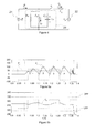
- Figures 5a and 5b illustrate a simulated response of the variable ⁇ ⁇ and the estimated fundamental frequency ⁇ 0 to disconnection of the main grid 22 power.
- the oscillations in both ⁇ ⁇ and ⁇ 0 were negligible. However, they grew considerably during the main grid 22 disconnection.
- Figures 6a and 6b show a simulated response of the variable ⁇ v and an RMS value V F , RMS of the voltage v F to disconnection of the main grid 22 power.
- the oscillations in both ⁇ v and the RMS value v F , RMS were negligible. However, they grew considerably during the main grid 22 disconnection.
- Figures 7a and 7b show a simulated time response of the main grid 22 current i g and the current reference i 0 * .
- the main grid 22 current i g shown in Figure 7a was already very small compared to the current reference i 0 * shown in Figure 7b , as most part of the current reference i 0 * was going through the RLC load 20. In fact, only a current due to the disturbance caused by the small reactive current injection appeared in Figure 7a .
Abstract
Description
- The present invention relates to distributed power generation, and particularly to detecting islanding conditions of a distributed power grid.
- Distributed generators (DG) provide means for generating power locally. Instead of centrally producing power to a main grid in a power plant, the power grid may be powered by a plurality of distributed generators.
- A distributed generator may comprise, for instance, a power source, such as a solar panel array or a wind turbine, and means for converting the power produced by the power source into a form in which it can be fed to the power grid. A frequency converter, for instance, may be used as the means for connecting the power source to the power grid.
- Islanding conditions refer to a state of a power grid in which a part of the electrical power grid is separated from the rest of the power grid. In this disclosure, a part which is separable from the rest of the power grid is referred to as a "distributed power grid", a "distributed grid", or simply a "grid". The part of the power grid from which the distributed grid may be separated is referred to as a "main grid".
- A distributed generator may continue its operation under islanding conditions, thus, producing power to the distributed grid. This may be a part of the function of the distributed generator. However, it may be important to stop the power production if an unintentional island has been produced. An unintentional island may, for instance, be caused by opening a breaker circuit either by maintenance personnel or simply because it has automatically tripped.
- Unintentional islanding can be dangerous to maintenance personnel. They may be unaware that a part of the power grid is still powered even though the connection to the main grid has been cut. Further, unintentional islanding may damage customer equipment because of uncontrolled voltage and frequency transient excursions during the islanding conditions and during the reclosing into an island.
- Therefore, it can be extremely important, for instance, in photovoltaic (PV) inverters to have a mechanism which immediately reacts upon detection of loss of main grid power and stops the power production.
- In many cases, detecting the loss of main grid power may be relatively easy, as islanding typically creates under/over voltage and under/over frequency conditions. These conditions can easily be detected and used by, for instance, relays of a generator in the distributed grid to disconnect, and, thus, stop the power production.
- However, when the power (both active and reactive components) generated by a distributed generator closely matches the power consumed by load or loads, detection of the islanding may become extremely difficult. Thus, the distributed generator may continue operation without detecting the islanding conditions [1].
- The requirement for detecting unintentional islanding in distributed power generation systems, and, in particular, in PV inverters, has motivated an intensive research and development of different detection methods. Several standards have been established to specify the conditions for disconnection during unintentional islanding. For instance, the Underwriters Laboratories Standard UL 1741 requires tripping of a distributed generator within 2 seconds after loss of the main grid power [4]. The German Standard DIN VDE 0126-1-1 proposes several islanding detection methods [5].
- In general, methods for detecting islanding conditions may be divided in three categories: passive methods, communication-based methods, and active methods [1, 2, 3]. These methods can also be divided into internal and external methods where an internal method may, for instance, reside inside a distributed generator, and an external method may, for instance, be implemented as an external device, between the distributed generator and the main grid.
- Passive methods typically monitor variables of the distributed grid in order to find abnormal changes in, for instance, frequency, voltage amplitude, phase angle, harmonics contents, etc. Passive methods are typically quite effective in most situations. However, their non-detection zone (NDZ), i.e. the range of loads for which the islanding detection method may fail, may be quite large.
- Communication-based methods usually operate on the basis of establishing communication channels between distributed generators and the main grid. Communications-based methods can detect islanding conditions even when the power produced matches the power consumed. However, the communications devices can be expensive. Implementing a communication-based method may also require co-operation of the main grid provider.
- Active methods typically detect a main grid power disconnection on the basis of observations on the response of the distributed grid to a disturbance intentionally introduced by the method. The response, or its magnitude, depends on the presence of the main grid power. Thus, islanding conditions may be determined on the basis of the response. In this manner, the NDZ can be minimized.
- However, the injected disturbances may decrease the quality of the power produced. The disturbance introduced to the network for islanding detection purposes may have a predefined maximum limit in order to keep the quality of the produced power at an acceptable level. For instance, according to standard UL 1741, the variations of the active and reactive power injected to the network should not exceed ± 3% of the rated apparent power of the distributed generator.
- An active method may, for instance, be implemented by introducing a small reactive current component in the current reference of a current controller of a distributed generator. Then, the method may monitor changes in, for instance, the load voltage, frequency and/or phase and detect islanding conditions on the basis of the changes [7, 8, 9].
- Another approach for an active method is to implement a positive feedback. A positive feedback of a distributed grid quantity, such as voltage, frequency or phase, may be added to a control reference controlling the produced power [10, 11]. For instance, in a voltage feedback scheme, the inverter may command more real power (or active current) when the distributed grid voltage amplitude is increased. As a result, the voltage keeps increasing to balance the real power. This continues until the voltage amplitude exceeds the protection limits, and thus the islanding can be detected. Similar approaches may be applied for a frequency feedback or a phase feedback.
- The positive feedback can be a very effective method in detecting islanding, as it forces the trajectories of voltage and frequency to abandon their monitored protection limits, thus producing an imminent detection of abnormal operation. Some authors propose to maintain continuous operation of these positive feedback schemes, under the assumption that the effect will be negligible during normal operation, i.e., during main grid connection, and will become unstable only if an islanding condition arise.
- However, there may be situations where the positive feedback methods can cause instabilities, even during normal operation conditions, i.e., under main grid connection [12].
- An object of the present invention is to provide a method and an apparatus for implementing the method so as to alleviate the above disadvantages. The objects of the invention are achieved by a method and an apparatus which are characterized by what is stated in the independent claims. The preferred embodiments of the invention are disclosed in the dependent claims.
- The aim of this disclosure is to present a new method for detecting islanding conditions of a distributed grid. The method operates on the basis of a principle of injecting a relatively small disturbance, for instance, in the form of a reactive current, into the distributed grid. The method uses two approaches in a two-stage process.
- In the first stage, the method monitors effects of the injected disturbance to a grid quantity or quantities, such as, for instance, the rate of change of voltage (ROCoV) and the rate of change of frequency (ROCoF). The disturbance can be dimensioned such that it causes only a negligible effect on these variables during normal operation, and a considerably larger effect when the main grid power is disconnected.
- The monitored quantities may then be compared to predefined thresholds, and the events these thresholds being exceeded may be counted. After a given number of these events has occurred within a given time, the first stage may presume that an islanding is detected, and then a second stage is enabled.
- In the second stage, a positive feedback loop or loops are enabled. If islanding conditions are present, the monitored quantities abandon their normal operation ranges, thus exceeding the over/under protection limits and, thereby, confirming the islanding conditions. Voltage amplitude variation and frequency variation, for instance, may be used for the positive feedback.
- By using the two-stage approach of the disclosed method, a more effective and precise detection of islanding condition can be achieved. The disclosed method minimizes the possibility of false tripping by reducing sensitivity to other perturbations. It also minimizes instabilities as the positive feedback schemes are not enabled at all times, but only if there is a certain likely-hood that an islanding occurred.
- In the following the invention will be described in greater detail by means of preferred embodiments with reference to the attached drawings, in which
-
Figures 1a to 1f illustrate various segments of an exemplary embodiment of the disclosed method; -
Figures 2a and 2b illustrate an example of a current reference; -
Figures 3a and 3b illustrate an example of detecting islanding conditions; -
Figure 4 illustrates a test setup using a balanced RLC load connected in parallel to the power electrical unit; -
Figures 5a and 5b illustrate a simulated response to disconnection of the main grid power; -
Figures 6a and 6b illustrate a simulated response to disconnection of the main grid power; -
Figures 7a and 7b show a simulated time response of the main grid current and the current reference; and -
Figure 8 illustrates a simulated time response of the main grid voltage and the voltage at the PCC. - The present disclosure proposes a method for detecting islanding conditions of a distributed grid. The disclosed method can be categorized as an active method. A disturbance is injected to the distributed grid and the islanding conditions are determined on the basis of the effect the disturbance has on one or more monitored quantities of the distributed grid.
- The method may, for instance, be implemented on a controller of a power electrical unit. A power electrical unit may be a distributed generator, for instance. The power electrical unit, such as a photovoltaic (PV) inverter, may, for instance, be used for transferring power between a renewable power source, such as a solar panel array, and a distributed power grid. Transfer of power through a power electrical unit in the distributed grid may be controlled on the basis of a control reference.
- The method comprises a first stage and a second stage. A less pervasive, first stage pre-processing method may first be used in detecting islanding. This pre-processing method may be operational at all times. After a certain confidence of islanding conditions is reached, the second stage may be activated.
- The first stage comprises injecting a reactive component to the control reference of the power electrical unit. For instance, a relatively small reactive current may be added to an original current reference controlling a current delivered to the distributed grid. Effects on, for instance, voltage amplitude and frequency produced by the injection of reactive current may then be measured.
- In other words, the final current reference may be composed of a dominant active (real) component used, for instance, for transferring the power generated in the energy source towards the distributed grid, and an additional, negligible reactive current component. The reactive component may, for instance, take the form of a square wave alternating between an inductive or capacitive current. Since the fundamental frequency of the distributed grid voltage may change during normal operation and during the islanding conditions, the square wave may, for instance, be synchronized with distributed grid voltage signal zero crossing. The alternation may run at a lower frequency. That is, the square wave may alternate from one state to another after a given number of zero crossings.
- After injecting the reactive component, a change in the quantity induced by the injected component may be determined for at least one electrical quantity of the grid. A disturbance induced by the injected component can be calibrated such that it causes negligible effects on the voltage signal during normal operation, i.e., when the main grid power is connected. However, it can cause considerable distortions on the grid quantities when the islanding conditions are present.
- On the basis of the change in the electrical quantity, it can be determined whether or not to move to the second stage of the disclosed method. For instance, the disturbances on the distributed grid quantities may be measured and compared to predefined thresholds, and each event of the thresholds being exceeded may be counted. The voltage amplitude, phase, frequency, the rate of change of voltage (ROCoV) and the rate of change of frequency (ROCoF) may, for instance, be the grid quantities used.
- After a given number of events, it can be presumed that an islanding condition is present, and the second stage can be enabled. A time window within which the events have to occur may be defined. For example, in some embodiments, islanding conditions may be presumed if the given amount of events has occurred within a time window of, for instance, two seconds.
- The second stage comprises, for at least one electrical quantity of the distributed grid, determining a value of the electrical quantity and forming a positive feedback term using the determined value. Feedback terms may, for instance, be formed from the distributed grid voltage amplitude and frequency. These feedback terms can be used separately, one at the time, or in combination.
- The positive feedback term or terms may then be added to the control reference and a change in an electrical quantity or electrical quantities induced by the feedback term or terms can be determined. The positive feedback causes the electrical quantities to abandon their normal operational ranges. The quantities exceed their predetermined, monitored maximum/minimum limits, thus, islanding condition may be determined on the basis of the change in the quantity induced by the feedback term.
- In case of the aforementioned voltage amplitude feedback, the active component of the output current reference can be modified by including a positive feedback term formed out of a variation of the distributed grid voltage amplitude. Variation in the active current mainly causes variation in the voltage amplitude. Therefore, if the variation in the voltage amplitude is positively fed back to modify the active current, then, it can be expected that the voltage amplitude will become unstable. The voltage amplitude will exceed the protection limits, which allows islanding detection.
- In case of a frequency feedback, the reactive component of the current reference may, for instance, be modified by introducing a positive feedback term formed out of a variation of distributed grid frequency. Variation in the reactive current mainly causes variation in the frequency of the voltage signal. Therefore, if variation in the frequency is positively fed back to modify the reactive current, it can be expected that the frequency will become unstable. The frequency will exceed the protection limits, which allows the islanding detection.
- The above disclosed method minimizes noise sensitivity since islanding conditions presumed in the more noise sensitive first stage are confirmed by the second stage. At the same time, possible instabilities can be minimized as the positive feedback of the second stage phase is enabled only if islanding conditions are presumed in the first phase. Unlike methods which check islanding conditions on a regular, periodic basis, the disclosed method can react immediately. The first stage may be continuously active, and the second stage, when activated by the first stage, reacts fast to islanding conditions.
-
Figures 1a to 1f illustrate an exemplary embodiment of the disclosed method. In the embodiment, a distributed generator comprising an inverter supplies a distributed grid. The inverter converts power produced by a power source to a form suitable to be supplied to the grid. In the embodiment, the controller controls the output current of the inverter. The embodied method may, for instance, be implemented on the controller of the inverter. - According to the disclosed method, the embodiment comprises two stages. In the first stage, the rates of change of voltage amplitude (ROCoV) and frequency (ROCoF) are determined. The second stage is based on a positive feedback scheme. Second stage positive feedbacks are enabled when islanding conditions are presumed to have appeared in the first stage.
- Some assumptions are made in analysing the embodiment. Power provided by the power source is assumed constant. A constant power is typical, for instance, in solar power applications where a suitable MPPT (Maximum Power Point Tracking) algorithm guarantees the position of the produced power in the MPP (Maximum Power Point) at all times. It is also assumed that the inverter control guarantees tracking of the grid side current towards its reference.
- The only input variables used in the analysis are an output
current reference 
- In the first stage of the disclosed method, a reactive component is injected to a control reference of a power electrical unit. In the embodiment illustrated in
Figures 1a to 1f , the control reference is represented by a current reference into which a small amount of alternating reactive current is intentionally injected in order to induce disturbances to electrical quantities of the distributed grid. Thus, a part of the embodiment consists in the construction of a current reference. The current reference for a current supplied to the distributed grid can be defined as follows
where PDc is an estimate of the power extracted from the power source, i.e., the maximum available power. The power source may, for instance, be a photovoltaic array. VF,1 is the fundamental component of the voltage vF and VF,RMS is the RMS value of the voltage vF . - In
Equation 1, thecurrent reference 
current reference 

where Qinj represents a desired reactive power to be injected. ϕ F,1 is a square phase signal of the voltage ν F,1 . That is, a signal with the same amplitude and frequency as the voltage ν F,1 , and with a phase shift of 90 degrees ahead. - The desired reactive power Qinj may, for instance, be selected to be a percentage x of the delivered active power,

In order to comply with, for instance, the above-mentioned standards concerning maximum disturbance allowed, the percentage may be limited to arange 0 < x ≤ 3%. - If the fundamental component ν F,1 and/or its square phase signal ϕF,1 are not directly available, they may, for instance, be calculated by using an adaptive quadrature signal generator (AQSG) illustrated in
Figure 1a , where an estimated fundamental voltage ν̂ F,1 and an estimated square phase signal F,1 are calculated on the basis of the voltage vF at the point of common coupling and the fundamental frequency ω0 . ν̃ F is a difference term representing the difference between the fundamental component VF,1 and its estimate F,1 . γ1 is a positive design parameter used to introduce a required damping to achieve convergence with stability. - In case the fundamental frequency ω0 is not available, for example, from an additional PLL, an estimated fundamental frequency ω̂0 is used instead of the fundamental frequency ω0. In
Figure 1a , such an estimate is used. -
Figure 1b illustrates a fundamental frequency estimator (FFE) which can, for instance, be used for calculating the estimate ω̂0 of the fundamental frequency. λ is a positive design parameter referred as the adaption gain.ω 0 is a nominal value of the fundamental frequency used as a feedforward term to improve the transient response during start up. - In
Figures 1a and 1b , signals ν̂ F,1 ϕ̂ F,1 and ω̂0 are each an output of an integrator. Therefore, the inputs of the integrators can be seen as time derivate terms

- The injected reactive current component may, for instance, take the form of a square wave. The current component may alternate between capacitive current and inductive current on the basis of the fundamental voltage. For this purpose, the sign of the fundamental component VF,1 can be extracted.
-
Figure 1c illustrates a scheme for the first stage where the sign of the estimated fundamental component ν̂ F,1 is extracted by using acomparator 10. The output of thecomparator 10 is fed to aseries 11 of T-flip-flops where each T-flip-flop divides the frequency by two. This yields a square wave. The square wave can be normalized to have only values -1 or 1. By using the T-flip-flops, the frequency of the square wave is a frequency of a fraction of the fundamental component, and synchronized with the zero crossings of the fundamental component. - For example, three T-flip-flops in series give a square wave alternating every 8th zero crossing of the fundamental component VF,1 .If the fundamental frequency is 50 Hz, the cycle frequency of the square wave is 6.25 Hz. If a time window for detecting threshold exceeding events in the first stage is, for instance, 2 s, the square wave makes 12.5 cycles in that time window. In other words, the square wave changes its state 25 times in the time window of 2 seconds.
- The square wave can now be used to change the sign of the reactive current component to be injected, thus changing its type between capacitive and inductive. In
segment 12 ofFigure 1c , the square wave produced by the T-flip-flops is used to produce the injected reactive power Qinj .Segment 13 is then used as means for injecting the reactive component to thecurrent reference 
Segment 13 produces thecurrent reference 
Equation 2. -
Figures 2a and 2b illustrate an example of the resultingcurrent reference 
Figure 2a , the reactive power Qinj in dashed line changes from capacitive current to inductive current. Thecurrent reference 
Figure 2b illustrates a change of the injected reactive power Qinj from inductive current to capacitive current. - In order to detect an event of exceeding a threshold in the first stage of the embodiment illustrated in
Figures 1a to 1f , variables representing electrical quantities of the distributed grid are created. These variables function as means for determining a change in the quantities induced by the injected reactive power Qinj . The variables should be sensitive to the reactive power Qinj during an islanding condition, but insensitive in normal situations, i.e., during main grid power connection. In other words, when the main grid power is connected, the reactive power Qinj should cause insignificant deviations on such variables. However, in an islanding condition, notable deviations should be expected in the variables. - The embodiment illustrated in
Figures 1a to 1f uses two variables related to a rate of change of voltage amplitude (ROCoV) and a rate of change of frequency (ROCoF). Time derivatives of the voltage amplitude and the frequency may be used to determine the rate of change of voltage (ROCoV) and the rate of change of frequency (ROCoF), respectively. The first variable δω related to ROCoF can, for instance, be defined as follows
- δω represents the absolute value (a measurement) of the ROCoF.
Figure 1d illustrates an exemplary implementation for constructing this term. The time derivative
Figure 1b . A low pass filter (LPF) is included inFigure 1d to filter out noise existent in this time derivative. Term ε2 can be used in a positive feedback scheme disclosed later. - The second variable δv can, for instance, be defined as follows

- δv represents the RMS value of the rate of change of the square of the amplitude, and can be considered as a measurement of the ROCoV.
-
Figure 1e shows an exemplary block diagram for constructing the second variable δv. An estimate

Figure 1a . The resulting implementation ofEquation 5 is based on a dot product of a vector of sinusoidal signals [ν̂ F,1, ϕ̂ F,1] T and a vector of time derivatives of the sinusoidal Signals
- Therefore, a band-pass filter (BPF) tuned at the 2nd harmonic of the fundamental may, as in
Figure 1e , be included to extract this component only, thus, minimizing additional noise. In addition, the BPF delivers a 2nd harmonic component signal α2 and its square phase signal β2 , out of which an RMS value can be easily computed. The variable ε1 inFigure 1e can be used in a positive feedback scheme which is disclosed later. - When the main grid is connected, the variables δω and δv are almost zero. However, if islanding conditions occur, the variables δω and δv grow considerably, thus, exceeding their corresponding thresholds Tω and Tv . The threshold Tω for the variable δω can, for instance, be tuned according to the following expression

where a criterion of 50% of the maximum expected peak value of measurement is used for the variable δω. The parameter x represents a percentage of the reference power PDc. It is used to fix the amplitude of the injected reactive current. In order to comply with standards concerning maximum disturbance allowed, the percentage x may, for instance, be limited to arange 0 < x ≤ 3%. - Accordingly, the threshold Tv can be formed for the variable δv , for instance, as follows

- On the basis of the changes in variables δω and δv , it can be determined whether or not to move to the second stage of the embodiment illustrated in
Figures 1a to 1f . The idea consists in counting, within a time window, events of deviations of the variables δω and δv exceeding their given thresholds Tω and T v . -
Figures 3a and 3b illustrate an example of the first stage of detecting islanding conditions using the embodiment illustrated inFigures 1a to 1f .Figure 3a shows the effect of islanding conditions on the variable δω representing the rate of change of frequency (ROCoF).Figure 3b shows the effect of islanding conditions on the variable δv representing the rate of change of voltage (ROCoV). - In
Figures 3a and 3b , the fundamental frequency is 50 Hz. The embodiment illustrated inFigures 1a to 1f has three T-flip-flops, and, as a result, the reactive current component (dashed line) shaped as a square wave has a cycle frequency of 6.25 Hz. Thus, the reactive current component changes between capacitive and inductive currents every 0.08 s. The islanding is produced at time t = 1 s, after which the excursions of both variables δω and δv grow considerably, thus exceeding their thresholds Tω and, respectively Tv . - In both
Figures 3a and 3b , five events (dotted circles) have been collected in a period of about 0.4 s. Only the first event per a change of the reactive current component is detected in order to reduce sensitivity to noise. The variable δω or the variable δv can be used alone or both can be used in combination in counting events. - Once a certain number of events, for instance, around 5 to 10, have been collected, it can be presumed that an island condition has occurred. To confirm this situation, the second stage of the embodiment illustrated in
Figures 1a to 1f may be enabled. - The second stage comprises, for at least one electrical quantity of the distributed grid, means for determining a value of the electrical quantity and forming a positive feedback term using the determined value. The purpose of the positive feedbacks is to drive voltage amplitude or frequency away from a normal operation range, for instance, in such a way that values of the determined electrical quantities exceed the over/under voltage protection (OVP/UVP) and/or over/under frequency protection (OFP/UFP) limits. Changes in electrical quantities induced by the feedback terms can be determined, for instance, by measuring, and, the islanding condition may be determined on the basis of the changes.
-
Figure 1f illustrates a block diagram of an implementation of the second stage which extends the scheme ofFigure 1 c by addingpositive feedback terms 14 to the control reference. Thefeedbacks 14 may be enabled when the second stage is activated. The implementation uses terms ε2 and ε1 presented inFigures 1 d and 1 e . Term ε2 contains information on the frequency variation while term ε1 contains information on the voltage amplitude variation. - In
Figure 1f , term ε2 and ε1 are fed back by means of positive gains kf and km respectively. Term ε1 adds to the reference power PDC ,thus modifying the amplitude of the active part of thecurrent reference 
- At the same time, term ε2 is added to the injected reactive power Qinj modifying the amplitude of the reactive part of the
current reference 
- The performance of the embodiment illustrated in
Figures 1a to 1f was simulated using a test setup proposed in standards UL 1741 and IEEE 929 [4, 6]. The test setup used abalanced RLC load 20 connected in parallel to the power electrical unit as shown inFigure 4 . - In
Figure 4 , the powerelectrical unit 21, such as a PV inverter, was represented by a simple current source as it was assumed that the output current i0 delivered to the distributed grid follows itsreference 
current source 21 provided power to amain grid 22 represented by a voltage source producing a voltage vg .The power PDC provided by thesource 21 was assumed constant. The range of thecurrent reference 
- In the simulations, a peak value Vpeak of the
main grid 22 voltage Vg was 325 V, an active delivered power PDC by thecurrent source 21 was 2680 W, and the fundamental frequency ω0 was 100π rad/s (50 Hz). InFigure 4 , an inductance Lg of 10 mH was used for themain grid 22. vF represented the voltage at the point of common coupling (PCC), and ig represented the current supplied to themain grid 22. - According to the standards, elements LF and CF of the
RLC load 20 were to be dimensioned in such a way that the resonance frequency of theRLC load 20 coincided with the nominal fundamental frequency ω0 of the main grid vg , i.e.,
- The resistor RF of the
RLC load 20 was designed to match the active power generated by thecurrent source 21, and the power quality factor Q, defined as
was defined to be equal to or higher than 2, i.e., Q ≥2 . This yielded the following expressions for computing values for the elements of RLC load 20
- Based on
Equations 10, the elements of theRLC load 20 had the following values: RF = 19.7 Ω, RF = 31.4 mH, and RF = 323.1 µF - For the AQSG according to
Figure 1a and the FFE according toFigure 1b gains y1 = 100 and λ = 0.1 were selected, respectively. The positive feedback loop gains have been fixed to km = 0.01 and kf = 4. The thresholds were tuned according toEquations 5 and 6 to values T ω = 61.98 and Tv = 0.438·105. Three T-flip-flops were used to generate a square wave, which yielded a cycle frequency of 6.25 Hz, thus, giving a change of state of the square wave in every 0.08 s. The second stage was set to be enabled if five events occurred within two seconds. An under/over frequency protection (UFP/OFP) limit of the second phase was set to 5%, and an under/over voltage protection (UVP/OVP) limit of the second phase was set to 10%. The main grid power was disconnected at t = 1 s. Therefore, it was expected that the islanding situation would be detected in the simulations before t = 3 s. Simulation results are shown inFigures 5a, 5b ,6a, 6b ,7a, 7b , and8 . -
Figures 5a and 5b illustrate a simulated response of the variable δω and the estimated fundamental frequency ω̂0 to disconnection of themain grid 22 power. Before the disconnection at t = 1 s time, the oscillations in both δω and ω̂0 were negligible. However, they grew considerably during themain grid 22 disconnection. The positive feedback was enabled after 5 events of δω exceeding the threshold Tω ,as shown inFigure 5a near t = 1.355 s. Once the positive feedback was enabled, the estimated frequency ω̂0 decreased very fast exceeding almost immediately the UFP/OFP fixed at ±5%. -
Figures 6a and 6b show a simulated response of the variable δv and an RMS value VF,RMS of the voltage vF to disconnection of themain grid 22 power. Before the main grid power was disconnected at t = 1 s, the oscillations in both δvand the RMS value vF,RMS were negligible. However, they grew considerably during themain grid 22 disconnection. As inFigures 5a and 5b , the second stage was enabled after five events of δvexceeding the threshold Tvas shown inFigure 6a . This happened also at around t =1.355 s. Once the second stage was enabled, the RMS voltage VF,RMS increased very fast exceeding almost immediately the UVP/OVP limits set at ±10%. -
Figures 7a and 7b show a simulated time response of themain grid 22 current ig and thecurrent reference 
main grid 22 current ig shown inFigure 7a was already very small compared to thecurrent reference 
Figure 7b , as most part of thecurrent reference 
RLC load 20. In fact, only a current due to the disturbance caused by the small reactive current injection appeared inFigure 7a . As expected, themain grid 20 current ig reduced to zero inFigure 7a when themain grid 20 power was disconnected at t = 1 s. Thecurrent reference 
main grid 22 disconnection until the positive feedback was enabled near t = 1.355 s. After that, thecurrent reference 
-
Figure 8 shows a simulated time response of themain grid 22 voltage Vg (dotted line), and the voltage vF at the PCC (solid line). Both voltages retain approximately similar shape and amplitude. However, once the positive feedback is enabled near t =1.335 s, the amplitude and frequency of the voltage vF start changing considerably. - It will be obvious to a person skilled in the art that, as the technology advances, the inventive concept can be implemented in various ways. The disclosed method and apparatus and their embodiments are not limited to the examples described above but may vary within the scope of the claims.
Claims (12)
- A method for detecting islanding conditions of a distributed grid, wherein transfer of power through a power electrical unit in the distributed grid is controlled on the basis of a control reference and the method comprises a first stage and a second stage, wherein the first stage comprises
injecting a reactive component to the control reference, and, for at least one electrical quantity of the grid,
determining a change in the quantity induced by the injected component, and
determining, on the basis of the change in the electrical quantity, whether or not to move to the second stage of the method, and
wherein the second stage comprises, for at least one electrical quantity of the grid,
determining a value of the electrical quantity,
forming a positive feedback term using the determined value
adding a positive feedback term to the control reference,
determining a change in an electrical quantity induced by the feedback term, and
determining islanding condition on the basis of the change in the quantity induced by the feedback term. - A method according to claim 1, wherein the transfer of power is controlled on the basis of a current reference.
- A method according to claim 2, wherein injecting a reactive component to the control reference comprises
injecting a reactive current component to the current reference, wherein the injected reactive current component takes the form of a square wave alternating between an inductive or a capacitive current. - A method according to any one of claims 1 to 3, wherein the reactive component is a square wave synchronized to zero crossings of a fundamental wave of a voltage of the grid.
- A method according to any one of claims 1 to 4, wherein determining a change in the quantity induced by the injected component in the first stage comprises
determining a change in the rate of change of the distributed grid voltage by the injected component. - A method according to any one of claims 1 to 5, wherein determining a change in the quantity induced by the injected component in the first stage comprises
determining a change in the rate of change of the distributed grid frequency by the injected component. - A method according to claim 5 or 6, wherein an estimate of the rate of change of the voltage is calculated by using an adaptive quadrature signal generator, and an estimate of the rate of change of the distributed grid frequency is calculated by using a fundamental frequency estimator.
- A method according to any one of claims 1 to 7, wherein determining whether or not to move to the second stage of the method comprises
comparing the change induced by the injected component in at least one electrical quantity to a predetermined limit,
counting events of the change exceeding the limit, and
proceeding to the second stage, if the amount of events exceed another limit within a set time window. - A method according to any one of claims 1 to 8, wherein the second stage comprises
forming a positive feedback term on the basis of the frequency variation of the distributed grid, and
adding the positive feedback term to the active part of the control reference. - A method according to any one of claims 1 to 9, wherein the second stage comprises
forming a positive feedback term on the basis of the amplitude variation of the distributed grid, and
adding the positive feedback term to the reactive part of the control reference. - An apparatus for detecting islanding conditions of a distributed grid, wherein transfer of power through a power electrical unit is controlled on the basis of a control reference and the apparatus comprises a first stage and a second stage, wherein the first stage comprises
means for injecting a reactive component to the control reference, and,
for at least one electrical quantity of the grid,
means for determining a change in the quantity induced by the injected component,
means for determining, on the basis of the change in the electrical quantity, whether or not to enable the second stage, and
wherein the second stage comprises, for at least one electrical quantity of the grid,
means determining a value of the electrical quantity,
means for forming a positive feedback term using the determined value,
means for adding a positive feedback term to the control reference, means for determining a change in an electrical quantity induced by the feedback term, and
means for determining islanding condition on the basis of the change in the quantity induced by the feedback term. - A photovoltaic inverter comprising an apparatus according to claim 11
Priority Applications (3)
| Application Number | Priority Date | Filing Date | Title |
|---|---|---|---|
| EP11187790.8A EP2590291B1 (en) | 2011-11-04 | 2011-11-04 | Method and apparatus for detecting islanding conditions of a distributed grid |
| ES11187790T ES2758573T3 (en) | 2011-11-04 | 2011-11-04 | Method and apparatus for detecting the island formation conditions of a distributed network |
| US13/668,797 US9331486B2 (en) | 2011-11-04 | 2012-11-05 | Method and apparatus for detecting islanding conditions of a distributed grid |
Applications Claiming Priority (1)
| Application Number | Priority Date | Filing Date | Title |
|---|---|---|---|
| EP11187790.8A EP2590291B1 (en) | 2011-11-04 | 2011-11-04 | Method and apparatus for detecting islanding conditions of a distributed grid |
Publications (2)
| Publication Number | Publication Date |
|---|---|
| EP2590291A1 true EP2590291A1 (en) | 2013-05-08 |
| EP2590291B1 EP2590291B1 (en) | 2019-09-04 |
Family
ID=44905664
Family Applications (1)
| Application Number | Title | Priority Date | Filing Date |
|---|---|---|---|
| EP11187790.8A Active EP2590291B1 (en) | 2011-11-04 | 2011-11-04 | Method and apparatus for detecting islanding conditions of a distributed grid |
Country Status (3)
| Country | Link |
|---|---|
| US (1) | US9331486B2 (en) |
| EP (1) | EP2590291B1 (en) |
| ES (1) | ES2758573T3 (en) |
Cited By (5)
| Publication number | Priority date | Publication date | Assignee | Title |
|---|---|---|---|---|
| CN104155555A (en) * | 2014-08-27 | 2014-11-19 | 阳光电源股份有限公司 | Active island detection method and device |
| CN104201720A (en) * | 2014-09-12 | 2014-12-10 | 阳光电源股份有限公司 | Control method and control device for suppression of resonance of grid-connected power generation system |
| CN105656054A (en) * | 2016-01-19 | 2016-06-08 | 华为技术有限公司 | Method and device for determining disturbance direction of reactive disturbance quantity |
| CN106291147A (en) * | 2015-05-14 | 2017-01-04 | 中国电力科学研究院 | A kind of detection method of inverter anti-isolated island protective value |
| US10003198B2 (en) | 2014-09-12 | 2018-06-19 | Sungrow Power Supply Co., Ltd. | Method and device for monitoring and suppressing resonance |
Families Citing this family (7)
| Publication number | Priority date | Publication date | Assignee | Title |
|---|---|---|---|---|
| WO2015023821A1 (en) * | 2013-08-14 | 2015-02-19 | Enphase Energy, Inc. | Method and apparatus for monitoring maximum power point tracking |
| US9520819B2 (en) | 2014-02-28 | 2016-12-13 | General Electric Company | System and method for controlling a power generation system based on a detected islanding event |
| CN103986153B (en) * | 2014-04-23 | 2016-06-29 | 清华大学 | Within the scope of interconnection of bulk power grids, coordinate to carry out the optimization method of balance of electric power and ener |
| CN104793148B (en) * | 2015-04-30 | 2017-10-13 | 国家电网公司 | Distributed generator islanding detection method based on grid entry point characteristic harmonics voltage measurement |
| US11239659B2 (en) * | 2019-06-10 | 2022-02-01 | Schweitzer Engineering Laboratories, Inc. | Microgrid autosynchronizing using remote recloser inputs and outputs |
| CN112782501B (en) * | 2020-12-02 | 2022-10-25 | 合肥工业大学 | Parameter-adaptive improved active frequency shift type island detection method |
| US11929608B2 (en) | 2021-09-01 | 2024-03-12 | Schweitzer Engineering Laboratories, Inc. | Systems and methods for operating an islanded distribution substation using inverter power generation |
Citations (4)
| Publication number | Priority date | Publication date | Assignee | Title |
|---|---|---|---|---|
| US20030165036A1 (en) * | 2002-01-16 | 2003-09-04 | Ballard Power Systems Corporation | Anti-islanding device and method for grid connected inverters using random noise injection |
| EP1764894A1 (en) * | 2005-09-19 | 2007-03-21 | ABB Schweiz AG | Method for detecting islanding operation of a distributed generator |
| US20070143044A1 (en) * | 2005-12-20 | 2007-06-21 | Yung-Fu Huang | Islanding detection and protection method |
| US7408268B1 (en) * | 2005-08-04 | 2008-08-05 | Magnetek, S.P.A. | Anti-islanding method and system for distributed power generation systems |
Family Cites Families (2)
| Publication number | Priority date | Publication date | Assignee | Title |
|---|---|---|---|---|
| CA2476030A1 (en) * | 2004-06-09 | 2005-12-09 | Wilsun Xu | A power signaling based technique for detecting islanding conditions in electric power distribution systems |
| US8334618B2 (en) * | 2009-11-13 | 2012-12-18 | Eaton Corporation | Method and area electric power system detecting islanding by employing controlled reactive power injection by a number of inverters |
-
2011
- 2011-11-04 ES ES11187790T patent/ES2758573T3/en active Active
- 2011-11-04 EP EP11187790.8A patent/EP2590291B1/en active Active
-
2012
- 2012-11-05 US US13/668,797 patent/US9331486B2/en active Active
Patent Citations (4)
| Publication number | Priority date | Publication date | Assignee | Title |
|---|---|---|---|---|
| US20030165036A1 (en) * | 2002-01-16 | 2003-09-04 | Ballard Power Systems Corporation | Anti-islanding device and method for grid connected inverters using random noise injection |
| US7408268B1 (en) * | 2005-08-04 | 2008-08-05 | Magnetek, S.P.A. | Anti-islanding method and system for distributed power generation systems |
| EP1764894A1 (en) * | 2005-09-19 | 2007-03-21 | ABB Schweiz AG | Method for detecting islanding operation of a distributed generator |
| US20070143044A1 (en) * | 2005-12-20 | 2007-06-21 | Yung-Fu Huang | Islanding detection and protection method |
Cited By (9)
| Publication number | Priority date | Publication date | Assignee | Title |
|---|---|---|---|---|
| CN104155555A (en) * | 2014-08-27 | 2014-11-19 | 阳光电源股份有限公司 | Active island detection method and device |
| CN104155555B (en) * | 2014-08-27 | 2017-02-15 | 阳光电源股份有限公司 | Active island detection method and device |
| CN104201720A (en) * | 2014-09-12 | 2014-12-10 | 阳光电源股份有限公司 | Control method and control device for suppression of resonance of grid-connected power generation system |
| US10003198B2 (en) | 2014-09-12 | 2018-06-19 | Sungrow Power Supply Co., Ltd. | Method and device for monitoring and suppressing resonance |
| CN106291147A (en) * | 2015-05-14 | 2017-01-04 | 中国电力科学研究院 | A kind of detection method of inverter anti-isolated island protective value |
| CN106291147B (en) * | 2015-05-14 | 2018-07-10 | 中国电力科学研究院 | A kind of detection method of the anti-isolated island protective value of inverter |
| US10551429B2 (en) | 2015-05-14 | 2020-02-04 | China Electric Power Research Institute | Method for detecting anti-island protection performance of inverter |
| CN105656054A (en) * | 2016-01-19 | 2016-06-08 | 华为技术有限公司 | Method and device for determining disturbance direction of reactive disturbance quantity |
| CN105656054B (en) * | 2016-01-19 | 2018-05-29 | 华为技术有限公司 | A kind of method and device of definite reactive disturbance amount perturbation direction |
Also Published As
| Publication number | Publication date |
|---|---|
| ES2758573T3 (en) | 2020-05-05 |
| EP2590291B1 (en) | 2019-09-04 |
| US9331486B2 (en) | 2016-05-03 |
| US20130114302A1 (en) | 2013-05-09 |
Similar Documents
| Publication | Publication Date | Title |
|---|---|---|
| EP2590291B1 (en) | Method and apparatus for detecting islanding conditions of a distributed grid | |
| US9170306B2 (en) | Islanding detection method and system | |
| Pouryekta et al. | Islanding detection and enhancement of microgrid performance | |
| US7906870B2 (en) | System and method for anti-islanding, such as anti-islanding for a grid-connected photovoltaic inverter | |
| Gkavanoudis et al. | A combined fault ride-through and power smoothing control method for full-converter wind turbines employing supercapacitor energy storage system | |
| US8497599B2 (en) | Electrical generator network and a local electrical system | |
| US8907525B2 (en) | Method and system for islanding detection and protection | |
| EP2501014B1 (en) | Method and apparatus for detecting islanding conditions of distributed generator | |
| Kim et al. | Frequency-shift acceleration control for anti-islanding of a distributed-generation inverter | |
| WO2013142553A2 (en) | System and method for islanding detection and protection | |
| CA2974872A1 (en) | Control method for a system comprising a frequency converter connected to a power grid | |
| Guha et al. | A novel passive islanding detection technique for converter-based distributed generation systems | |
| Elshrief et al. | Fast and accurate islanding detection technique for microgrid connected to photovoltaic system | |
| Chakraborty et al. | Integrated control algorithm for fast and accurate detection of the voltage sag with low voltage ride-through (LVRT) enhancement for doubly-fed induction generator (DFIG) based wind turbines | |
| Elshrief et al. | Methods for protecting network from islanding danger. | |
| CN104198841A (en) | Method for detecting island in photovoltaic grid-connected inverter | |
| Mazhari et al. | Locking frequency band exposure method for islanding detection and prevention in distributed generation | |
| Reis et al. | Evaluation of active frequency drift anti-islanding methods with a single-phase grid-tie photovoltaic inverter | |
| Yu et al. | Boundary conditions of reactive-power-variation method and active-frequency-drift method for islanding detection of grid-connected photovoltaic inverters | |
| EP2937965B1 (en) | Detection of islanding state in electricity network | |
| Winter et al. | Islanding Dependencies and Detection in low-Voltage grids with grid forming Inverters | |
| KR101568712B1 (en) | An islanding detection apparatus and method with partial phase window monitoring method on grid connected inverter | |
| Dube et al. | Comparative analysis of passive islanding detection methods for grid-connected Distrubted Generators | |
| Alam | Current injection disturbance based voltage drift control for anti-islanding of photovoltaic inverter system | |
| YARRA | Analysis of Synchronization and Islanding Detection Methods for Single-Stage Microgrids |
Legal Events
| Date | Code | Title | Description |
|---|---|---|---|
| PUAI | Public reference made under article 153(3) epc to a published international application that has entered the european phase |
Free format text: ORIGINAL CODE: 0009012 |
|
| AK | Designated contracting states |
Kind code of ref document: A1 Designated state(s): AL AT BE BG CH CY CZ DE DK EE ES FI FR GB GR HR HU IE IS IT LI LT LU LV MC MK MT NL NO PL PT RO RS SE SI SK SM TR |
|
| AX | Request for extension of the european patent |
Extension state: BA ME |
|
| 17P | Request for examination filed |
Effective date: 20131105 |
|
| RBV | Designated contracting states (corrected) |
Designated state(s): AL AT BE BG CH CY CZ DE DK EE ES FI FR GB GR HR HU IE IS IT LI LT LU LV MC MK MT NL NO PL PT RO RS SE SI SK SM TR |
|
| RIN1 | Information on inventor provided before grant (corrected) |
Inventor name: COCCIA, ANTONIO Inventor name: HO, NGAI-MAN Inventor name: TIMBUS, ADRIAN Inventor name: ESCOBAR, GERARDO Inventor name: OUDALOV, ALEXANDRE Inventor name: PETTERSSON, SAMI Inventor name: SERPA, LEONARDO-AUGUSTO |
|
| GRAP | Despatch of communication of intention to grant a patent |
Free format text: ORIGINAL CODE: EPIDOSNIGR1 |
|
| STAA | Information on the status of an ep patent application or granted ep patent |
Free format text: STATUS: GRANT OF PATENT IS INTENDED |
|
| INTG | Intention to grant announced |
Effective date: 20190401 |
|
| GRAS | Grant fee paid |
Free format text: ORIGINAL CODE: EPIDOSNIGR3 |
|
| GRAA | (expected) grant |
Free format text: ORIGINAL CODE: 0009210 |
|
| STAA | Information on the status of an ep patent application or granted ep patent |
Free format text: STATUS: THE PATENT HAS BEEN GRANTED |
|
| RAP1 | Party data changed (applicant data changed or rights of an application transferred) |
Owner name: ABB SCHWEIZ AG |
|
| AK | Designated contracting states |
Kind code of ref document: B1 Designated state(s): AL AT BE BG CH CY CZ DE DK EE ES FI FR GB GR HR HU IE IS IT LI LT LU LV MC MK MT NL NO PL PT RO RS SE SI SK SM TR |
|
| REG | Reference to a national code |
Ref country code: GB Ref legal event code: FG4D |
|
| REG | Reference to a national code |
Ref country code: CH Ref legal event code: EP |
|
| REG | Reference to a national code |
Ref country code: AT Ref legal event code: REF Ref document number: 1176725 Country of ref document: AT Kind code of ref document: T Effective date: 20190915 |
|
| REG | Reference to a national code |
Ref country code: DE Ref legal event code: R096 Ref document number: 602011061751 Country of ref document: DE |
|
| REG | Reference to a national code |
Ref country code: IE Ref legal event code: FG4D |
|
| REG | Reference to a national code |
Ref country code: NL Ref legal event code: MP Effective date: 20190904 |
|
| REG | Reference to a national code |
Ref country code: LT Ref legal event code: MG4D |
|
| PG25 | Lapsed in a contracting state [announced via postgrant information from national office to epo] |
Ref country code: LT Free format text: LAPSE BECAUSE OF FAILURE TO SUBMIT A TRANSLATION OF THE DESCRIPTION OR TO PAY THE FEE WITHIN THE PRESCRIBED TIME-LIMIT Effective date: 20190904 Ref country code: FI Free format text: LAPSE BECAUSE OF FAILURE TO SUBMIT A TRANSLATION OF THE DESCRIPTION OR TO PAY THE FEE WITHIN THE PRESCRIBED TIME-LIMIT Effective date: 20190904 Ref country code: NO Free format text: LAPSE BECAUSE OF FAILURE TO SUBMIT A TRANSLATION OF THE DESCRIPTION OR TO PAY THE FEE WITHIN THE PRESCRIBED TIME-LIMIT Effective date: 20191204 Ref country code: BG Free format text: LAPSE BECAUSE OF FAILURE TO SUBMIT A TRANSLATION OF THE DESCRIPTION OR TO PAY THE FEE WITHIN THE PRESCRIBED TIME-LIMIT Effective date: 20191204 Ref country code: SE Free format text: LAPSE BECAUSE OF FAILURE TO SUBMIT A TRANSLATION OF THE DESCRIPTION OR TO PAY THE FEE WITHIN THE PRESCRIBED TIME-LIMIT Effective date: 20190904 Ref country code: HR Free format text: LAPSE BECAUSE OF FAILURE TO SUBMIT A TRANSLATION OF THE DESCRIPTION OR TO PAY THE FEE WITHIN THE PRESCRIBED TIME-LIMIT Effective date: 20190904 |
|
| PG25 | Lapsed in a contracting state [announced via postgrant information from national office to epo] |
Ref country code: LV Free format text: LAPSE BECAUSE OF FAILURE TO SUBMIT A TRANSLATION OF THE DESCRIPTION OR TO PAY THE FEE WITHIN THE PRESCRIBED TIME-LIMIT Effective date: 20190904 Ref country code: GR Free format text: LAPSE BECAUSE OF FAILURE TO SUBMIT A TRANSLATION OF THE DESCRIPTION OR TO PAY THE FEE WITHIN THE PRESCRIBED TIME-LIMIT Effective date: 20191205 Ref country code: RS Free format text: LAPSE BECAUSE OF FAILURE TO SUBMIT A TRANSLATION OF THE DESCRIPTION OR TO PAY THE FEE WITHIN THE PRESCRIBED TIME-LIMIT Effective date: 20190904 Ref country code: AL Free format text: LAPSE BECAUSE OF FAILURE TO SUBMIT A TRANSLATION OF THE DESCRIPTION OR TO PAY THE FEE WITHIN THE PRESCRIBED TIME-LIMIT Effective date: 20190904 |
|
| REG | Reference to a national code |
Ref country code: AT Ref legal event code: MK05 Ref document number: 1176725 Country of ref document: AT Kind code of ref document: T Effective date: 20190904 |
|
| PG25 | Lapsed in a contracting state [announced via postgrant information from national office to epo] |
Ref country code: NL Free format text: LAPSE BECAUSE OF FAILURE TO SUBMIT A TRANSLATION OF THE DESCRIPTION OR TO PAY THE FEE WITHIN THE PRESCRIBED TIME-LIMIT Effective date: 20190904 Ref country code: AT Free format text: LAPSE BECAUSE OF FAILURE TO SUBMIT A TRANSLATION OF THE DESCRIPTION OR TO PAY THE FEE WITHIN THE PRESCRIBED TIME-LIMIT Effective date: 20190904 Ref country code: PL Free format text: LAPSE BECAUSE OF FAILURE TO SUBMIT A TRANSLATION OF THE DESCRIPTION OR TO PAY THE FEE WITHIN THE PRESCRIBED TIME-LIMIT Effective date: 20190904 Ref country code: EE Free format text: LAPSE BECAUSE OF FAILURE TO SUBMIT A TRANSLATION OF THE DESCRIPTION OR TO PAY THE FEE WITHIN THE PRESCRIBED TIME-LIMIT Effective date: 20190904 Ref country code: PT Free format text: LAPSE BECAUSE OF FAILURE TO SUBMIT A TRANSLATION OF THE DESCRIPTION OR TO PAY THE FEE WITHIN THE PRESCRIBED TIME-LIMIT Effective date: 20200106 Ref country code: RO Free format text: LAPSE BECAUSE OF FAILURE TO SUBMIT A TRANSLATION OF THE DESCRIPTION OR TO PAY THE FEE WITHIN THE PRESCRIBED TIME-LIMIT Effective date: 20190904 |
|
| REG | Reference to a national code |
Ref country code: ES Ref legal event code: FG2A Ref document number: 2758573 Country of ref document: ES Kind code of ref document: T3 Effective date: 20200505 |
|
| PG25 | Lapsed in a contracting state [announced via postgrant information from national office to epo] |
Ref country code: SM Free format text: LAPSE BECAUSE OF FAILURE TO SUBMIT A TRANSLATION OF THE DESCRIPTION OR TO PAY THE FEE WITHIN THE PRESCRIBED TIME-LIMIT Effective date: 20190904 Ref country code: CZ Free format text: LAPSE BECAUSE OF FAILURE TO SUBMIT A TRANSLATION OF THE DESCRIPTION OR TO PAY THE FEE WITHIN THE PRESCRIBED TIME-LIMIT Effective date: 20190904 Ref country code: IS Free format text: LAPSE BECAUSE OF FAILURE TO SUBMIT A TRANSLATION OF THE DESCRIPTION OR TO PAY THE FEE WITHIN THE PRESCRIBED TIME-LIMIT Effective date: 20200224 Ref country code: SK Free format text: LAPSE BECAUSE OF FAILURE TO SUBMIT A TRANSLATION OF THE DESCRIPTION OR TO PAY THE FEE WITHIN THE PRESCRIBED TIME-LIMIT Effective date: 20190904 |
|
| REG | Reference to a national code |
Ref country code: DE Ref legal event code: R097 Ref document number: 602011061751 Country of ref document: DE |
|
| REG | Reference to a national code |
Ref country code: CH Ref legal event code: PL |
|
| PLBE | No opposition filed within time limit |
Free format text: ORIGINAL CODE: 0009261 |
|
| STAA | Information on the status of an ep patent application or granted ep patent |
Free format text: STATUS: NO OPPOSITION FILED WITHIN TIME LIMIT |
|
| PG2D | Information on lapse in contracting state deleted |
Ref country code: IS |
|
| PG25 | Lapsed in a contracting state [announced via postgrant information from national office to epo] |
Ref country code: CH Free format text: LAPSE BECAUSE OF NON-PAYMENT OF DUE FEES Effective date: 20191130 Ref country code: LI Free format text: LAPSE BECAUSE OF NON-PAYMENT OF DUE FEES Effective date: 20191130 Ref country code: LU Free format text: LAPSE BECAUSE OF NON-PAYMENT OF DUE FEES Effective date: 20191104 Ref country code: DK Free format text: LAPSE BECAUSE OF FAILURE TO SUBMIT A TRANSLATION OF THE DESCRIPTION OR TO PAY THE FEE WITHIN THE PRESCRIBED TIME-LIMIT Effective date: 20190904 Ref country code: MC Free format text: LAPSE BECAUSE OF FAILURE TO SUBMIT A TRANSLATION OF THE DESCRIPTION OR TO PAY THE FEE WITHIN THE PRESCRIBED TIME-LIMIT Effective date: 20190904 Ref country code: IS Free format text: LAPSE BECAUSE OF FAILURE TO SUBMIT A TRANSLATION OF THE DESCRIPTION OR TO PAY THE FEE WITHIN THE PRESCRIBED TIME-LIMIT Effective date: 20200105 |
|
| 26N | No opposition filed |
Effective date: 20200605 |
|
| REG | Reference to a national code |
Ref country code: BE Ref legal event code: MM Effective date: 20191130 |
|
| PG25 | Lapsed in a contracting state [announced via postgrant information from national office to epo] |
Ref country code: SI Free format text: LAPSE BECAUSE OF FAILURE TO SUBMIT A TRANSLATION OF THE DESCRIPTION OR TO PAY THE FEE WITHIN THE PRESCRIBED TIME-LIMIT Effective date: 20190904 |
|
| GBPC | Gb: european patent ceased through non-payment of renewal fee |
Effective date: 20191204 |
|
| PG25 | Lapsed in a contracting state [announced via postgrant information from national office to epo] |
Ref country code: GB Free format text: LAPSE BECAUSE OF NON-PAYMENT OF DUE FEES Effective date: 20191204 Ref country code: FR Free format text: LAPSE BECAUSE OF NON-PAYMENT OF DUE FEES Effective date: 20191104 Ref country code: IE Free format text: LAPSE BECAUSE OF NON-PAYMENT OF DUE FEES Effective date: 20191104 |
|
| PG25 | Lapsed in a contracting state [announced via postgrant information from national office to epo] |
Ref country code: BE Free format text: LAPSE BECAUSE OF NON-PAYMENT OF DUE FEES Effective date: 20191130 |
|
| PG25 | Lapsed in a contracting state [announced via postgrant information from national office to epo] |
Ref country code: CY Free format text: LAPSE BECAUSE OF FAILURE TO SUBMIT A TRANSLATION OF THE DESCRIPTION OR TO PAY THE FEE WITHIN THE PRESCRIBED TIME-LIMIT Effective date: 20190904 |
|
| PG25 | Lapsed in a contracting state [announced via postgrant information from national office to epo] |
Ref country code: HU Free format text: LAPSE BECAUSE OF FAILURE TO SUBMIT A TRANSLATION OF THE DESCRIPTION OR TO PAY THE FEE WITHIN THE PRESCRIBED TIME-LIMIT; INVALID AB INITIO Effective date: 20111104 Ref country code: MT Free format text: LAPSE BECAUSE OF FAILURE TO SUBMIT A TRANSLATION OF THE DESCRIPTION OR TO PAY THE FEE WITHIN THE PRESCRIBED TIME-LIMIT Effective date: 20190904 |
|
| PG25 | Lapsed in a contracting state [announced via postgrant information from national office to epo] |
Ref country code: TR Free format text: LAPSE BECAUSE OF FAILURE TO SUBMIT A TRANSLATION OF THE DESCRIPTION OR TO PAY THE FEE WITHIN THE PRESCRIBED TIME-LIMIT Effective date: 20190904 |
|
| PG25 | Lapsed in a contracting state [announced via postgrant information from national office to epo] |
Ref country code: MK Free format text: LAPSE BECAUSE OF FAILURE TO SUBMIT A TRANSLATION OF THE DESCRIPTION OR TO PAY THE FEE WITHIN THE PRESCRIBED TIME-LIMIT Effective date: 20190904 |
|
| PGFP | Annual fee paid to national office [announced via postgrant information from national office to epo] |
Ref country code: ES Payment date: 20230125 Year of fee payment: 12 |
|
| PGFP | Annual fee paid to national office [announced via postgrant information from national office to epo] |
Ref country code: IT Payment date: 20231124 Year of fee payment: 13 Ref country code: DE Payment date: 20231121 Year of fee payment: 13 |